Article

Ripple Formation during Oblique Angle Etching

1
Green Center for Systems Biology, University of Texas Southwestern Medical Center, Forest Park, Dallas, TX 75390, USA
2
Department of Physics and Astronomy, University of Arkansas at Little Rock, Little Rock, AR 72211, USA
*
Author to whom correspondence should be addressed.
Coatings 2019, 9(4), 272; https://doi.org/10.3390/coatings9040272
Submission received: 18 January 2019 / Revised: 12 April 2019 / Accepted: 17 April 2019 / Published: 22 April 2019
(This article belongs to the Special Issue Modelling and Simulation of Coating 2019)

Abstract

:
Chemical removal of materials from the surface is a fundamental step in micro- and nano-fabrication processes. In conventional plasma etching, etchant molecules are non-directional and perform a uniform etching over the surface. However, using a highly directional obliquely incident beam of etching agent, it can be possible to engineer surfaces in the micro- or nano- scales. Surfaces can be patterned with periodic morphologies like ripples and mounds by controlling parameters including the incidence angle with the surface and sticking coefficient of etching particles. In this study, the dynamic evolution of a rippled morphology has been investigated during oblique angle etching (OAE) using Monte Carlo simulations. Fourier space and roughness analysis were performed on the resulting simulated surfaces. The ripple formation was observed to originate from re-emission and shadowing effects during OAE. Our results show that the ripple wavelength and root-mean-square roughness evolved at a more stable rate with accompanying quasi-periodic ripple formation at higher etching angles (θ > 60°) and at sticking coefficient values (Sc) 0.5 ≤ Sc ≤ 1. On the other hand, smaller etching angle (θ < 60°) and lower sticking coefficient values lead to a rapid formation of wider and deeper ripples. This result of this study can be helpful to develop new surface patterning techniques by etching.

1. Introduction

Morphological evolution of surfaces during thin film deposition [1] has been the interest of many researchers for applications in industries including micro- and nano- electronics and mechanical systems [2]. Surface morphology controls many important physical and chemical properties of thin films [3]. It is therefore of great interest to understand and control the evolution of the surface morphology during etching. The noise competes with surface smoothing processes to form a rough morphology if the experiment is performed at either a sufficiently low temperature or at a high growth rate. This preferential growth on “hills” further roughens the surface, typically leading to the formation of columnar structures [4,5,6]. Due to the non-local, long-range, geometrical nature of the shadowing effect, it dominates over smoothening effects of surface diffusion [7,8,9,10]. During etching, as illustrated in Figure 1a, obliquely incident etching particles can preferentially remove the tops of “hills” due to their higher heights, while lower lying “valleys” get shadowed and stay intact. Therefore, shadowing has a smoothening effect during the etching process as opposed to its roughening effect in deposition and dominates over the roughening effect of noise, leading to very smooth surfaces [7,11,12]. However, it has been shown that [13] etched surfaces can remarkably get rougher due to the competition between shadowing and “re-emission effects.” Etching particles with a non-unity sticking coefficient (Sc), which defines the probability of etching a surface atom (for example, Sc = 1 stands for 100% probability of etching the surface atom, and Sc = 0.1 for 10%), can desorb/bounce-off from the first impact point, get re-emitted, and finally etch another surface point after multiple re-emission steps.
Karabacak et al. [14,15] summarized some of the experimentally measured sticking coefficient values reported in the literature. Boyd et al. has used an oblique reactive ion etching (RIE) flux incident on a patterned substrate in order to investigate the angular dependence of etching rate during RIE [16], but did not report on the morphological evolution. Ripple formation has been believed to be mainly due to competition between roughening effects and surface viscous flow [17]. Vourdas et al. [18] proposed a lithography-less, plasma-directed assembly-organization method, which is an ion-enhanced etching mechanism with simultaneous deposition of etch inhibitors. The roughness generated in thin films during their etching by plasma processes can be an important issue for the correct operation of the fabricated device. Martin et al. [19] showed that experimental silicon etching process can smooth a pre-existing roughness. Memos et al. [20] reported a modelling study investigating the effect of surface charging on the surface roughness of plasma-etched polymeric substrates. Ono et al. [21] has reviewed experimental and simulation studies on the surface morphology evolution during plasma etching, which reported ripple formation under the presence of obliquely incident energetic ions. More recently, Nakasaki et al. carried out an experimental and simulation investigation of ripple formation on silicon that results from an obliquely incident Cl-based plasma incorporating energetic ionic species [22], consistent with the previous studies reported in Ono’s review [21]. On the other hand, most of these plasma etching studies mainly focused on the contribution of the scattering/reflection of energetic ionic species in the ripple formation. Being inspired by the glancing angle deposition technique, we proposed an “oblique angle etching (OAE)” approach and reported some preliminary results obtained from Monte Carlo simulations [23]. In this etching technique, the beam of zero-kinetic energy etching particles is highly directional and obliquely incident on the film surface. By controlling the shadowing effect through the angle of etching particles with non-unity sticking coefficients, it is possible to engineer surfaces having morphologies like periodic ripples and mounds at the micro- or nano-scales. Different than conventional plasma etching or RIE, in OAE, the removal of surface atoms occurs through chemical reactions with the low or zero-kinetic energy incident particles, and no significant bulk processes are involved. Therefore, OAE offers an alternative method of surface engineering through the control of shadowing and re-emission effects without any bulk damage that typically occurs in obliquely ion-bombarded surfaces. In this work, we investigate the OAE approach in detail using Monte Carlo simulation methods and present a framework for future experimental studies. In our study, we modify a conventional plasma etching simulation method to allow zero-kinetic-energy obliquely incident particles that leads to the OAE simulations.

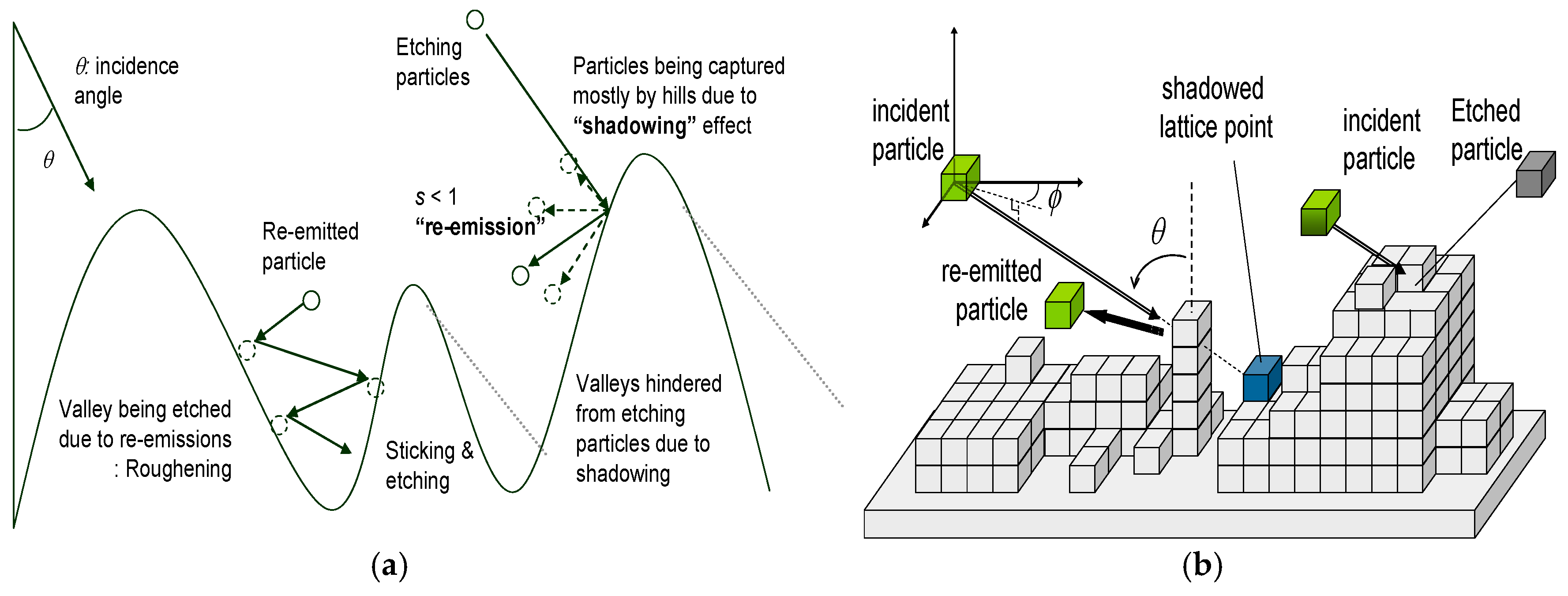
2. Monte Carlo Simulations

In order to explore the evolution of the surface morphology during OAE, we developed Monte Carlo (MC) simulations that consider shadowing [24,25,26], re-emission, and noise effects [23]. MC Simulation codes for the OAE process were developed in a C++ environment. Simulation parameters, such as lattice size, etching angle, sticking coefficients, number of particles sent to the surface, and surface diffusion, can be defined by the user. In the simulations, cubic lattice points form the (i, j, k) lattice structure. We assigned each particle a dimension of one lattice unit. We used continuous boundary conditions with 512 × 512 (= i × j) lattice size. Figure 1b illustrates the basic processes included in our OAE simulations. Briefly, a particle is sent toward the surface with polar angle θ and azimuthal angle ϕ. Some surface points are shadowed from the initial incident flux, as well as from the re-emitted particles due to the nearby higher surface features. The incident particle etches the surface point of first impact with probability Sc. If the particle does not etch, then it is re-emitted. If it finds another surface feature on its way, it may etch that point also with probability Sc. The total number of particles sent for each simulation performed was 2.5 × 10⁸. In our study, we did not include surface diffusion effects. Previously it has been showed that surface diffusion is less significant compared to shadowing and re-emission effects [7,8,9]. We also assumed that the kinetic energies of the incident particles are negligible, and hence no momentum transfer takes place when particles land on the surface. In addition, no overhangs were allowed.

3. Results and Discussion

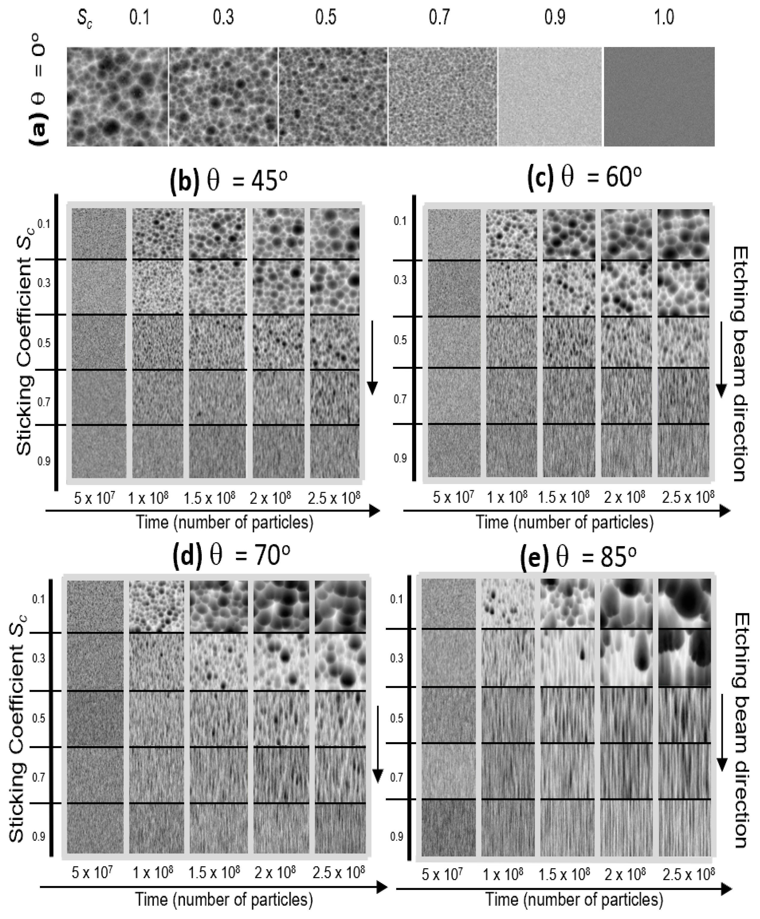
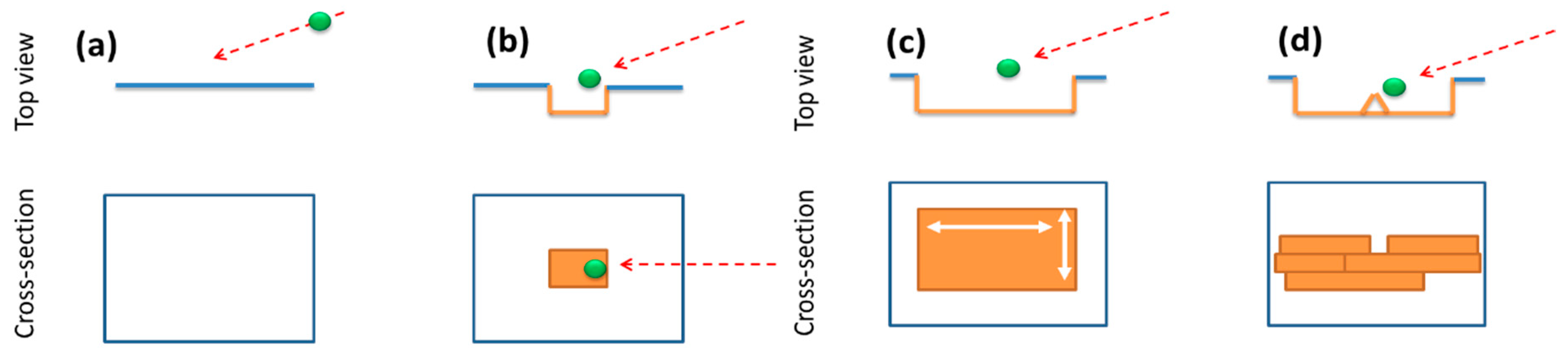
3.1. Morphology of Oblique Angle Etched (OAE) Surfaces

A visual comparison in Figure 2 indicates that the surface morphology moved towards a rippled structure elongated in the beam direction as the sticking coefficient Sc is increased. The ripple formation seemed to be more dominant for high etching angles larger than 60°. For angles at 45° and 60°, surfaces show an anisotropic morphology, especially for sticking coefficient values at 0.7 and 0.9, but not a clear ripple structure. On the other hand, at higher oblique etching angles of 70° and 85°, we could clearly see ripple formation for sticking coefficients in the range 0.5 ≤ Sc < 1. In addition, ripples were found to form along the oblique etching flux direction.
We believe this directionality originated from re-emission and shadowing effects, which is illustrated in Figure 3. During OAE, particles initially began etching a perfectly smooth surface (Figure 3a), randomly leaving tiny “valleys” and “hills” on the surface (Figure 3b). These height fluctuations initiated the shadowing effect and played a key role in the development of the directionality of ripples. Due to a shadowing effect, sidewalls of a hill facing towards the incident beam (front side) were etched faster compared to its opposite shadowed side (back side). However, because of the cosine distribution of re-emitted particles along the local surface normal, the back sides also experienced etching through the particles being reflected from the front sides of other hills. Figure 2a shows the surface morphologies at later stages of normal incidence (θ = 0°) etching at various sticking coefficients Sc. It can be clearly seen that low sticking coefficient values led to rougher surfaces due to the re-emission effect. As the sticking coefficient was increased, etching became “random,” which led to a relatively smoother surface. Re-emitted particles could start etching sidewalls, which resulted in the widening of valleys and eventually merging two neighbouring ripples. These results are consistent with a previous study by Zhao et al. [13].
This ripple widening behaviour can be more clearly observed at high etching angles of θ = 70° and 85°, as shown in Figure 2d,e, respectively. Ripple formation was enhanced by increased shadowing and was strongly correlated to re-emission. From the comparison of Figure 2b,c, an anisotropic morphology was observed even at lower incidence angles (θ = 45° and 60°) of OAE; however, the shadowing effect is not strong enough to produce a clear ripple structure at these levels. Thus, at small sticking coefficients, re-emission leads to a more uniform and isotropic etching rather than a surface with wave formations.

3.2. Dynamic Evolution Roughness and Ripple Wavelength during OAE

In order to investigate the dynamic evolution of rippled morphology during OAE in detail, we performed roughness and Fourier space analysis on the simulated surfaces. For this purpose, we calculated the root-mean-square (RMS) roughness ω values during the simulation at each time, at intervals of 2.5 × 10⁴ particles. RMS roughness is defined in detail where elsewhere [15]. Fourier space analysis can provide an insight into whether there exists a periodic [27] morphology defined with a surface wavelength λ, which is critical in accurately defining a rippled topography. The process can be understood in further detail through the analysis of dynamic evolution of RMS roughness as plotted in Figure 4b. Log–log plots of ω versus simulation time present more detailed information for initial stages and allow for the measurement of growth exponent β values simply through the measurement of slope values (ω~tβ). As can be seen in the Figure 4b, in stage I, the surface quickly developed a roughness with ω reaching up to ≈0.5 lattice unit with β values about 0.3–0.4 for all the sticking coefficients. Then in stage II, we saw a slower increase in roughness values indicated by β values close to ≈0.1. This increase was accompanied by small fluctuations in roughness that originated from the competition between the shadowing and re-emission effects. As the surface became rougher due to the re-emission effect, shadowing became more pronounced on etching the hills, and therefore reduced the roughness, giving rise to fluctuations in stage II. In this stage, we did not observe clear ripples. This competitive behaviour along with small β values remained until the surface reached a critical roughness value of about ω ≈ 1 lattice unit. At stage III, smaller sticking coefficients resulted in a faster increase in roughness, which was also indicated by larger β values. β increased from about 0.25 up to ≈0.5 as the sticking coefficient was decreased from 0.9 to 0.5. This rapid evolution of roughness at smaller sticking coefficients occurred along with the faster increase in the ripple wavelength. Therefore, this corresponded to wider (i.e., larger λR) and deeper (i.e., higher ω) ripples forming at a faster pace for smaller sticking coefficients. We observed a similar behaviour in the evolution of ripple wavelength and roughness for surfaces etched at different oblique angles while we kept the sticking coefficient constant, as shown in Figure 4c,d.
Higher etching angles led to smaller λR values with a steady linear increase, which is similar to the results of higher sticking coefficients in Figure 4a. This is expected because an increase in either the etching angle or sticking coefficient both results in a relative increase the shadowing effect and decrease in re-emission. On the other hand, as the deposition angle is decreased, thus the strength of the shadowing effect decreases, therefore making the re-emission effect more pronounced and leading to wider ripples with wavelengths increasing in an unstable way (Figure 4c). Similarly, the RMS roughness evolution of surfaces etched at different angles (Figure 4d) shows a similar overall behaviour to that of surfaces etched with different sticking coefficients (Figure 4b). However, surfaces reached the critical roughness value of ω ≈ 1 lattice unit that separated stages II and III at different times when the deposition angle was changed. Smaller etching angles resulted in wider and deeper ripples, and higher angles provided a more stable increase, both in ripple wavelength and roughness.

4. Conclusions

In conclusion, we investigated the ripple formation during an oblique angle etching process which originated from shadowing and re-emission effects. The mechanism during oblique angle etching, which is a type of chemical etching by low energy particles, is quite different than the previously reported ripple formation during ion-beam bombarded surfaces where the incident ions have much higher energies, and surface and subsurface bulk atoms are physically dislocated or removed (sputtered) from the substrate. We performed simulations for a wide range of etching angle and sticking coefficient values in order to vary the strength of shadowing and re-emission effects, respectively. Our results indicate that quasi-periodic ripple formation was enhanced at oblique etching angles θ > 60° and for sticking coefficients in the range 0.5 ≤ Sc < 1. Ripple wavelength and root-mean-square roughness evolved at a slow, yet more stable rate for higher etching angles and sticking coefficient values. On the other hand, smaller etching angles and lower sticking coefficients led to rapid formation of wider and deeper ripples. The results in this study can be useful in developing and the experimental design of new surface patterning techniques based on oblique angle etching.

Author Contributions

M.F.C. performed Monte Carlo simulations and analyzed the data. M.Y. contributed in organizing the data in preparation of the manuscript. T.K. oversaw the overall project.

Funding

This research received no external funding.

Acknowledgments

Authors would like to thank staff of Department of Physics and Astronomy, and Applied Science Graduate Program for their help in providing administrative and academic support during the course of this project.

Conflicts of Interest

The authors declare no conflict of interest.

References

  1. Zhao, Y.; Wang, G.-C.; Lu, T.-M. Characterization of Amorphous and Crystalline Rough Surface-Principles and Applications; Elsevier: Amsterdam, The Netherlands, 2000. [Google Scholar]
  2. Leondes, C.T. MEMS/NEMS Handbook; Springer: New York, NY, USA, 2006. [Google Scholar]
  3. Lüth, H. Solid Surfaces, Interfaces and Thin Films; Springer: Berlin, Germany, 2001. [Google Scholar]
  4. Karabacak, T.; Wang, G.-C.; Lu, T.-M. Physical self-assembly and the nucleation of three-dimensional nanostructures by oblique angle deposition. J. Vac. Sci. Technol. A Vac. Surf. Film 2004, 22, 1778–1784. [Google Scholar] [CrossRef]
  5. Antartis, D.A.; Mott, R.N.; Chasiotis, I. Silicon nanosprings fabricated by glancing angle deposition for ultra-compliant films and interfaces. Mater. Des. 2018, 144, 182–191. [Google Scholar] [CrossRef]
  6. Karabacak, T.; Lu, T. Shadowing growth and physical self-assembly of 3D columnar structures. In Handbook of Theoretical and Computational Nanotechnology; Rieth, M., Schommers, W., Eds.; American Scientific Publishers: Stevenson Ranch, CA, USA, 2005; pp. 729–779. [Google Scholar]
  7. Lu, T.-M.; Zhao, Y.-P.; Drotar, J.; Karabacak, T.; Wang, G.-C. Novel mechanisms on the growth morphology of films. MRS Online Proc. Libr. Arch. 2002, 749. [Google Scholar] [CrossRef]
  8. Pelliccione, M.; Karabacak, T.; Lu, T.-M. Breakdown of dynamic scaling in surface growth under shadowing. Phys. Rev. Lett. 2006, 96, 146105. [Google Scholar] [CrossRef]
  9. Karabacak, T.; Zhao, Y.-P.; Wang, G.-C.; Lu, T.-M. Growth-front roughening in amorphous silicon films by sputtering. Phys. Rev. B 2001, 64, 085323. [Google Scholar] [CrossRef]
  10. Yuksel, M.; Karabacak, T.; Guclu, H. Networking behavior in thin film and nanostructure growth dynamics. In Proceedings of the 2nd international conference on Nano-Networks, Catania, Italy, 24–26 September 2007; ICST: Brussels, Belgium, 2007. [Google Scholar]
  11. Li, L.; Zhang, C.; Tuan, C.-C.; Chen, Y.; Wong, C. High-aspect-ratio microstructures with versatile slanting angles on silicon by uniform metal-assisted chemical etching. J. Micromech. Microeng. 2018, 28, 055006. [Google Scholar] [CrossRef] [Green Version]
  12. Drotar, J.T.; Zhao, Y.-P.; Lu, T.-M.; Wang, G.-C. Mechanisms for plasma and reactive ion etch-front roughening. Phys. Rev. B 2000, 61, 3012. [Google Scholar] [CrossRef]
  13. Zhao, Y.-P.; Drotar, J.T.; Wang, G.-C.; Lu, T.-M. Roughening in plasma etch fronts of Si(100). Phys. Rev. Lett. 1999, 82, 4882. [Google Scholar] [CrossRef]
  14. Karabacak, T.; Guclu, H.; Yuksel, M. Network behavior in thin film growth dynamics. Phys. Rev. B 2009, 79, 195418. [Google Scholar] [CrossRef]
  15. Karabacak, T. Thin-film growth dynamics with shadowing and re-emission effects. J. Nanophotonics 2011, 5, 052501. [Google Scholar] [CrossRef]
  16. Boyd, G.D.; Coldren, L.A.; Storz, F.G. Directional reactive ion etching at oblique angles. Appl. Phys. Lett. 1980, 36, 583–585. [Google Scholar] [CrossRef]
  17. Umbach, C.C.; Headrick, R.L.; Chang, K.-C. Spontaneous nanoscale corrugation of ion-eroded sio 2: The role of ion-irradiation-enhanced viscous flow. Phys. Rev. Lett. 2001, 87, 246104. [Google Scholar] [CrossRef]
  18. Vourdas, N.; Kontziampasis, D.; Kokkoris, G.; Constantoudis, V.; Goodyear, A.; Tserepi, A.; Cooke, M.; Gogolides, E. Plasma directed assembly and organization: Bottom-up nanopatterning using top-down technology. Nanotechnology 2010, 21, 085302. [Google Scholar] [CrossRef]
  19. Martin, M.; Cunge, G. Surface roughness generated by plasma etching processes of silicon. J. Vac. Sci. Technol. B Microelectron. Nanom. Struct. Meas. Phenom. 2008, 26, 1281–1288. [Google Scholar] [CrossRef]
  20. Memos, G.; Lidorikis, E.; Kokkoris, G. Roughness evolution and charging in plasma-based surface engineering of polymeric substrates: The effects of ion reflection and secondary electron emission. Micromachines 2018, 9, 415. [Google Scholar] [CrossRef]
  21. Ono, K.; Nakazaki, N.; Tsuda, H.; Takao, Y.; Eriguchi, K. Surface morphology evolution during plasma etching of silicon: Roughening, smoothing and ripple formation. J. Phys. D Appl. Phys. 2017, 50, 414001. [Google Scholar] [CrossRef]
  22. Nakazaki, N.; Matsumoto, H.; Sonobe, S.; Hatsuse, T.; Tsuda, H.; Takao, Y.; Eriguchi, K.; Ono, K. Ripple formation on Si surfaces during plasma etching in Cl2. AIP Adv. 2018, 8, 055027. [Google Scholar] [CrossRef]
  23. Cansizoglu, M.F.; Karabacak, T. Engineering morphology of surfaces by oblique angle etching. MRS Online Proc. Libr. Arch. 2007, 1059. [Google Scholar] [CrossRef]
  24. Yurukcu, M. An Investigation of Conformality of the Core-shell Polymer Electrolyte Membrane (PEM) Fuel Cell Catalysts by Sputter Deposition. Ph.D. Thesis, University of Arkansas, Little Rock, AR, USA, May 2018. [Google Scholar]
  25. Yurukcu, M.; Cansizoglu, H.; Cansizoglu, M.; Karabacak, T. Conformality of PVD shell layers on vertical arrays of rods with different aspect ratios investigated by monte carlo simulations. MRS Adv. 2017, 2, 465–470. [Google Scholar] [CrossRef]
  26. Cansizoglu, H.; Yurukcu, M.; Cansizoglu, M.; Karabacak, T. Investigation of physical vapor deposition techniques of conformal shell coating for core/shell structures by monte carlo simulations. Thin Solid Films 2015, 583, 122–128. [Google Scholar] [CrossRef]
  27. Karabacak, T.; Wang, G.-C.; Lu, T.-M. Quasi-periodic nanostructures grown by oblique angle deposition. J. Appl. Phys. 2003, 94, 7723–7728. [Google Scholar] [CrossRef]
Figure 1. Shadowing and re-emission effects during etching (a) and Monte Carlo simulations of oblique angle etching (OAE) (b) are illustrated.
Coatings 09 00272 g001
Figure 2. Simulated morphological evolution for sticking coefficient values Sc = 0.1, 0.3, 0.5, 0.7 and 0.9 at OAE etching angles (a) θ = 0°, (b) 45°, (c) 60°, (d) 70°, (e) 85°.
Coatings 09 00272 g002
Figure 3. Proposed mechanism of ripple formation during OAE is illustrated. (a) Starting Surface, (b) Initial roughness formation through its and bumps during random etching, (c) Elongation of initial pits due to shadowing effect leading to the formation of valleys, and widening of valleys through re-emission effect, (d) Merging of valleys after removal of the hills separating them, and further widening due to the re-emission.
Coatings 09 00272 g003
Figure 4. Dynamic evolution of ripple wavelength λR (a) and RMS roughness ω (b) for different sticking coefficients Sc = 0.5, 0.7, 0.9 at an etching angle of θ = 85°; and dynamic evolution of ripple wavelength λR (c) and RMS roughness ω (d) for different etching angles θ = 60°, 70°, 85°.
Coatings 09 00272 g004

