Structure-Property Relationships in Suspension HVOF Nano-TiO2 Coatings

 ,
, 
Abstract
1. Introduction
2. Materials and Methods
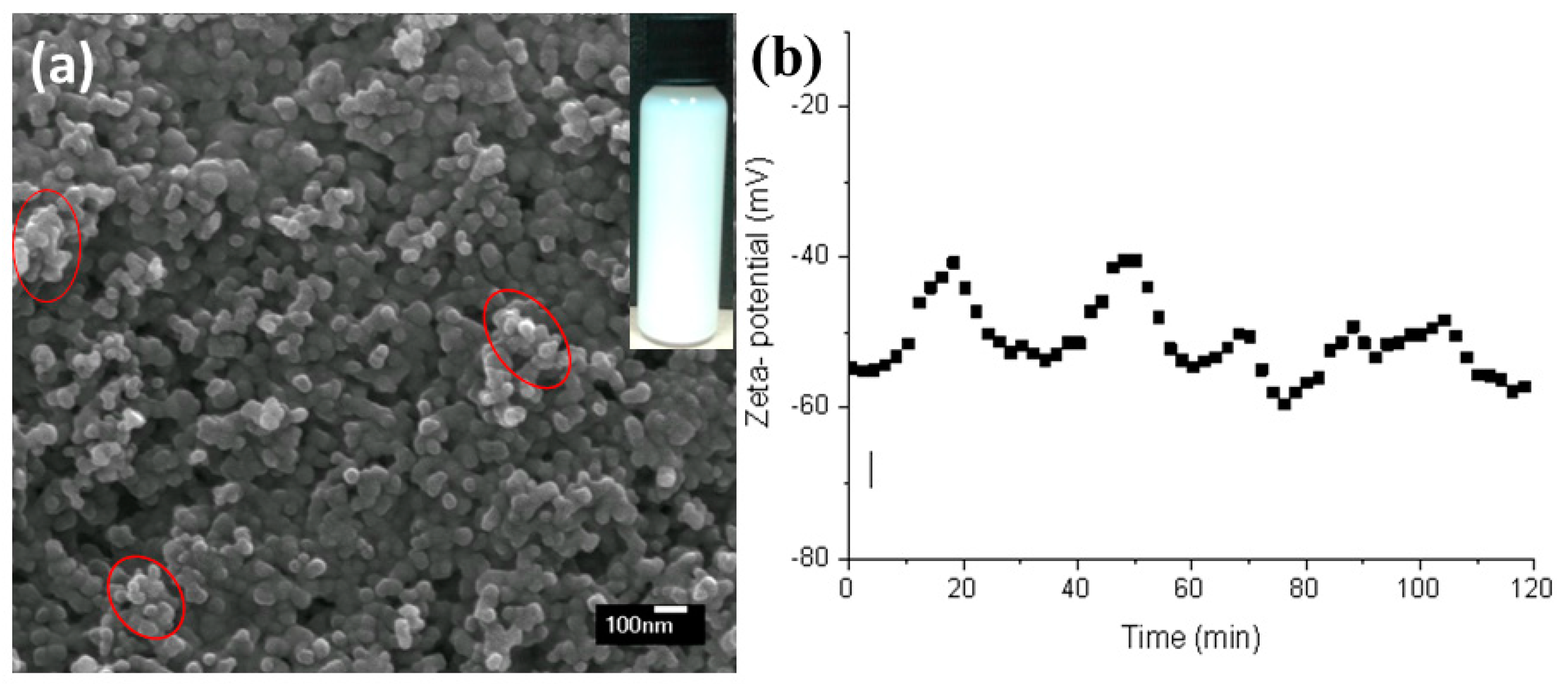
2.1. Suspension Preparation
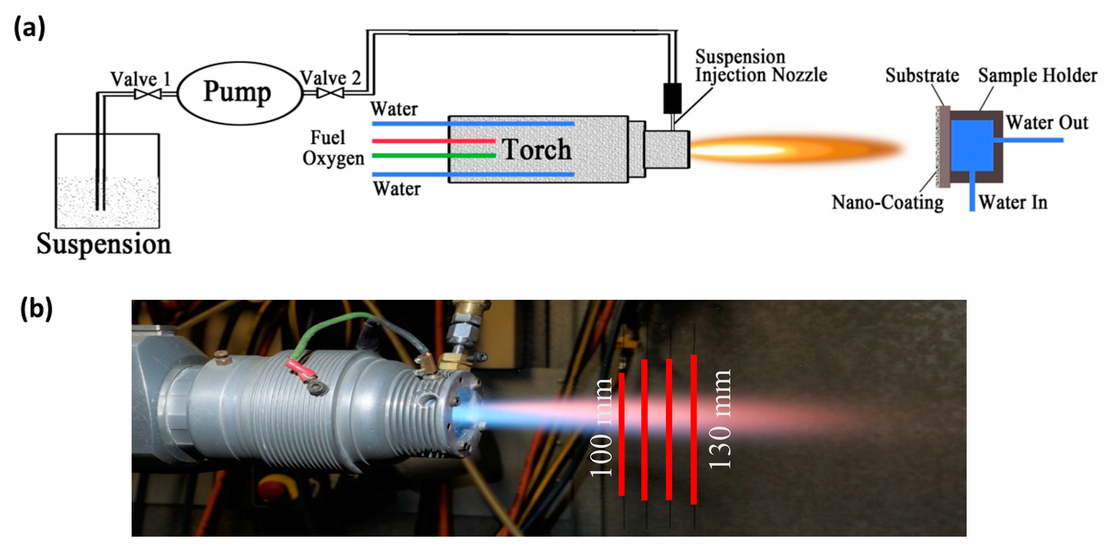
2.2. Spray Process
2.3. Coating Characterisation
3. Results
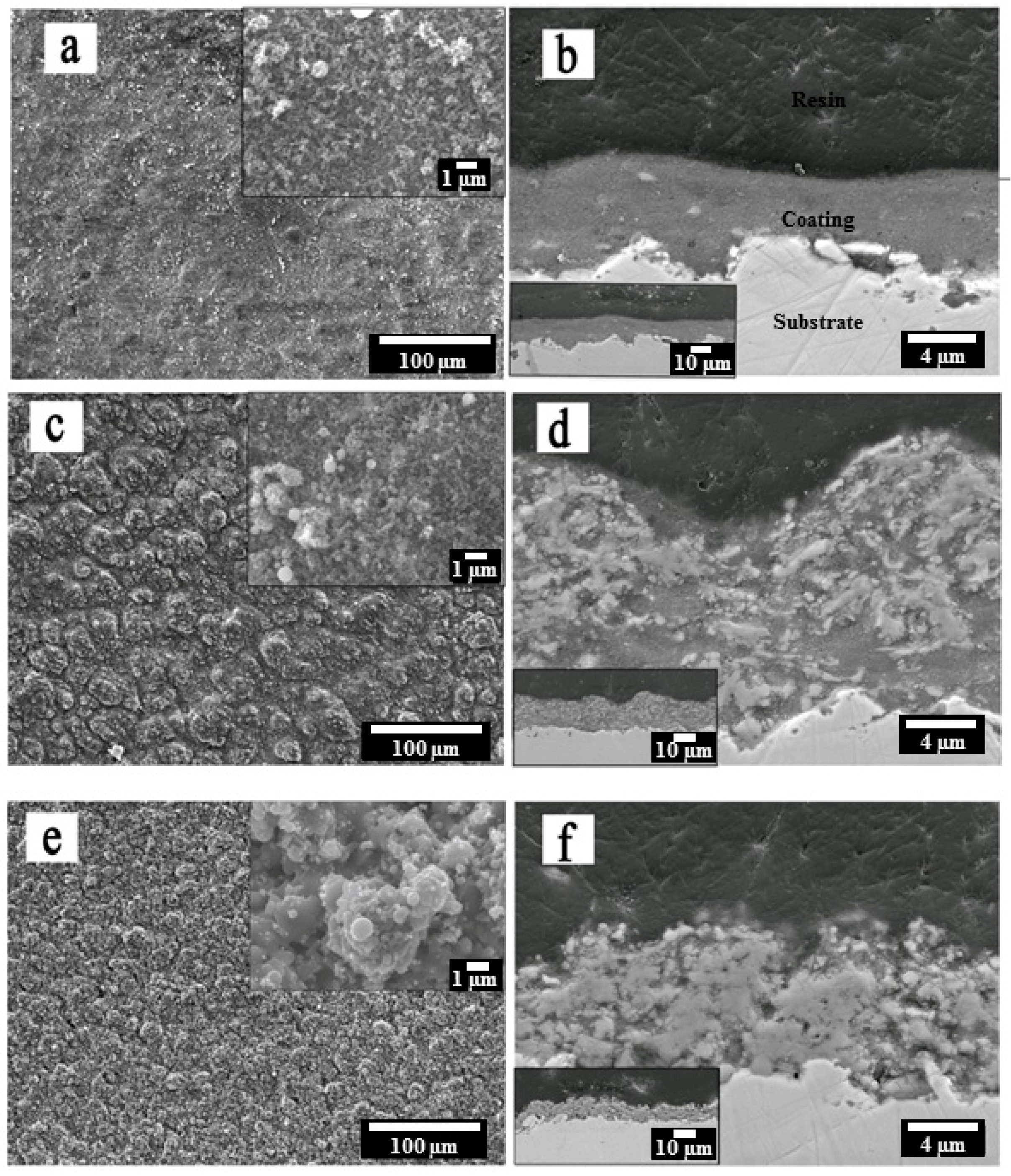
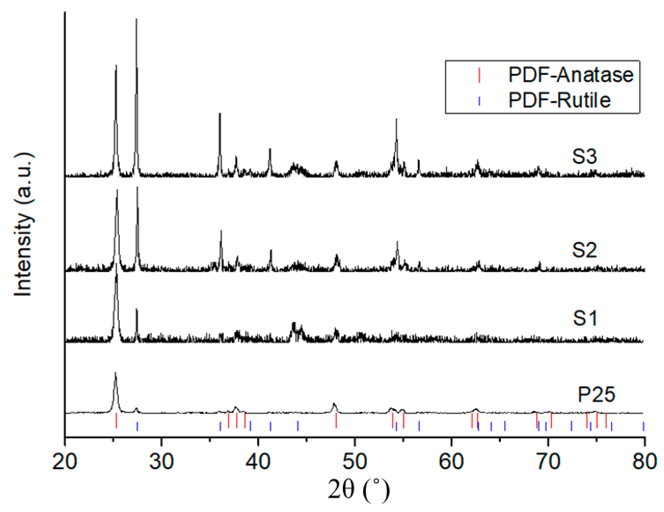
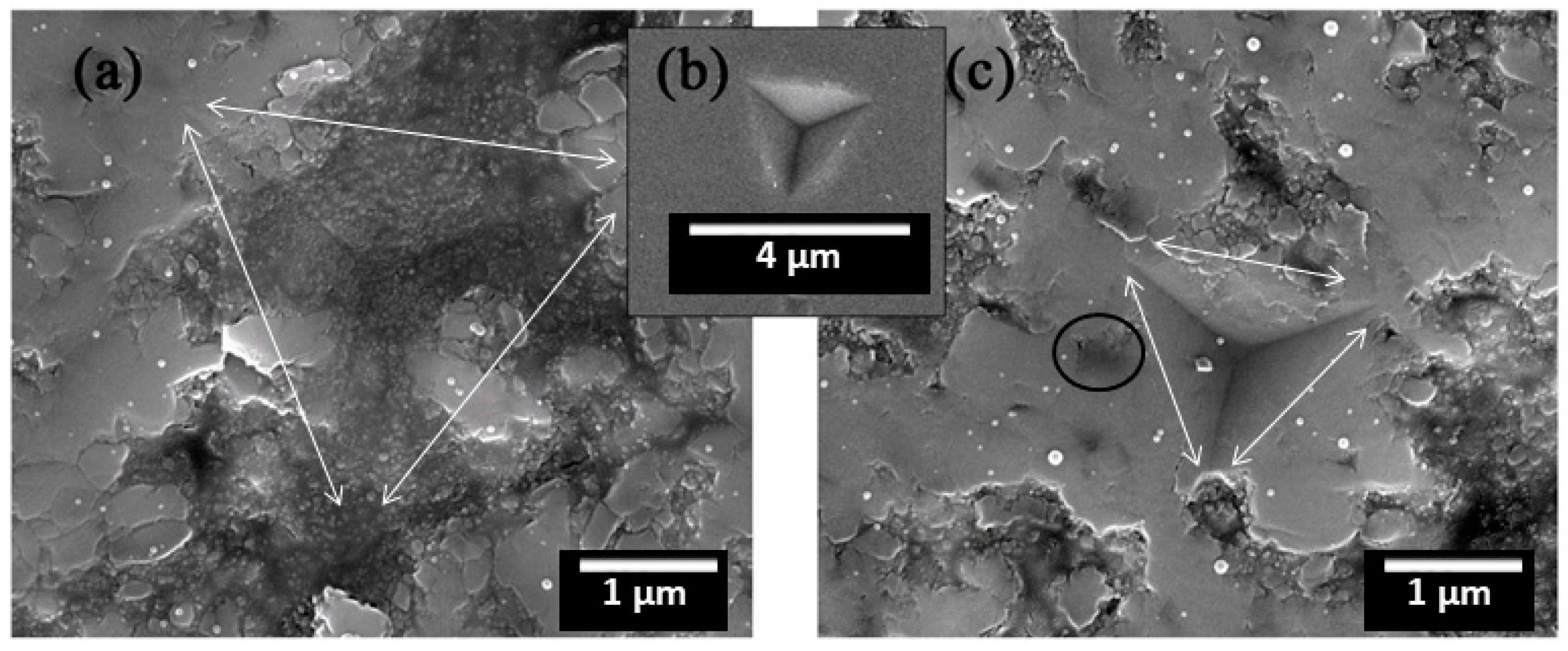
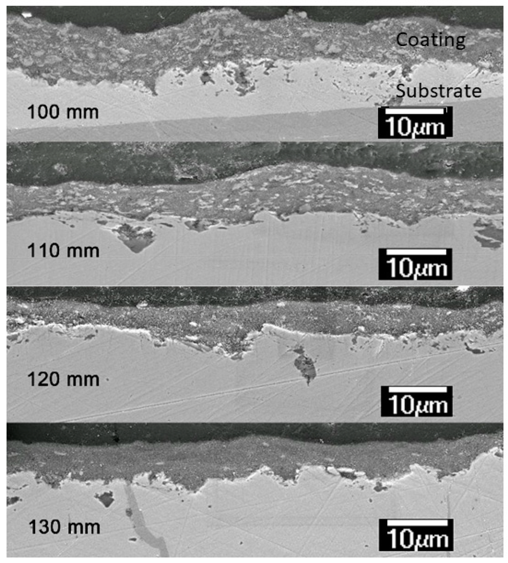
3.1. Microstructure
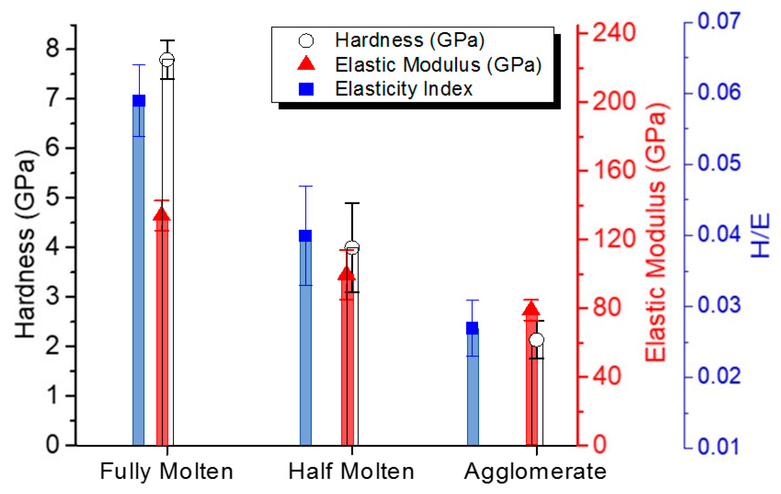
3.2. Mechanical Properties
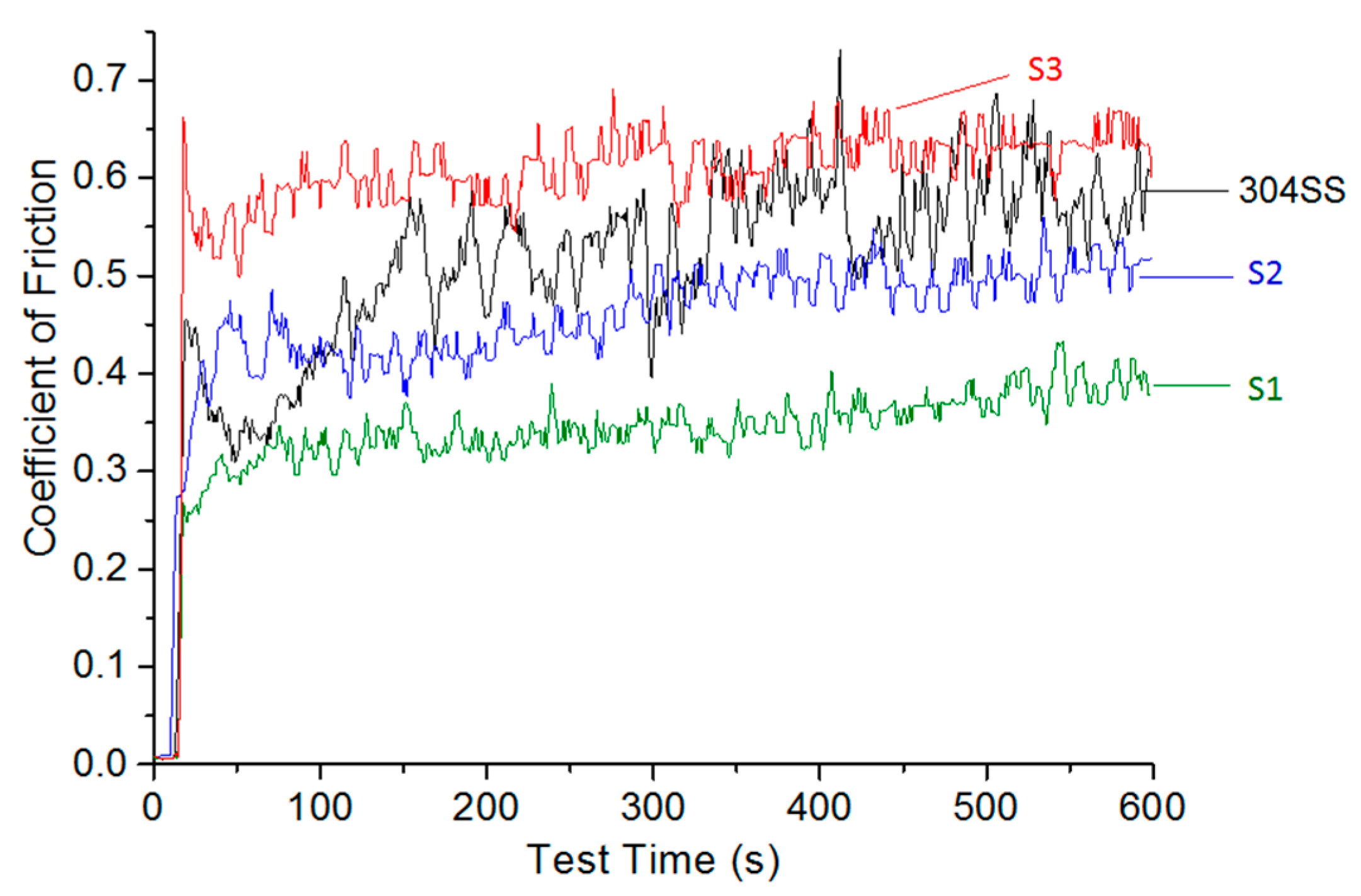
3.3. Friction and Wear Behaviour
4. Discussion
5. Conclusions
- Increasing extents of feedstock melting corresponded to increased rutile contents in the coatings, which led to an increase in overall hardness with a reduced plasticity.
- The as-sprayed surface roughness did not seem play an important role for tribological performance of the developed coatings when their Ra varied between 0.53 and 1.18 µm.
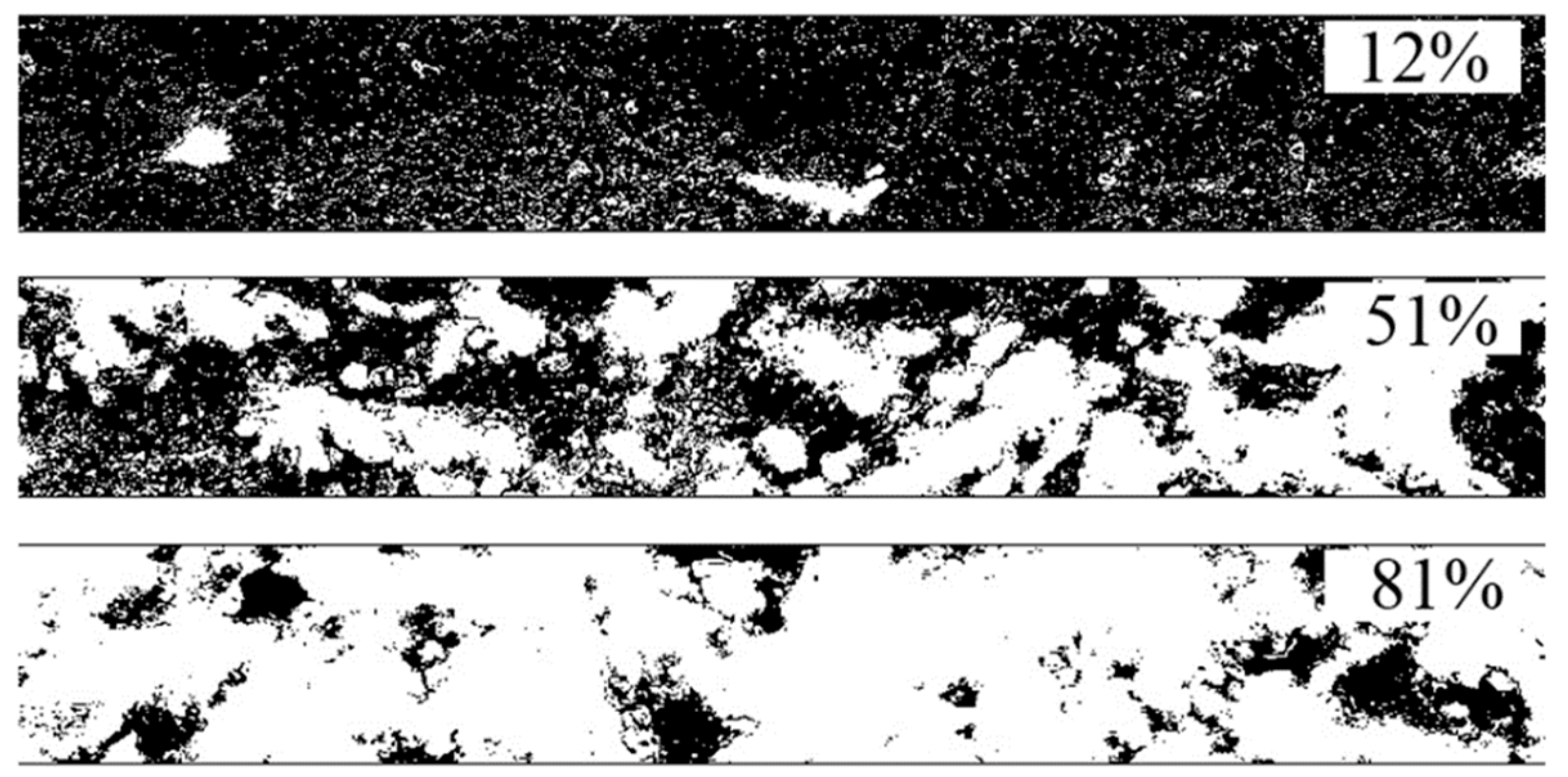
- The coating composed of most agglomerate particles (12% melted particles) had the lowest coefficient of friction, whereas the coating composed of mostly melted particles (81% melted particles) presented the highest coefficient of friction. Results also indicate that a higher fraction of agglomerated particles (proportional to anatase content) were beneficial to the formation of tribo-film at sliding surfaces.
- Wear resistance of the coatings were proven to be not rational to their hardness. The coating with mostly agglomerate particles (12% melted splats) had the lowest wear rate and the coating with moderate melted particles (51%) had the worst performance against wear.
Author Contributions
Funding
Acknowledgments
Conflicts of Interest
References
- Toma, F.-L.; Potthoff, A.; Berger, L.-M.; Leyens, C. Demands, potentials, and economic aspects of thermal spraying with suspensions: A critical review. J. Therm. Spray Technol. 2015, 24, 1–10. [Google Scholar] [CrossRef]
- Lima, R.S.; Marple, B.R. Thermal spray coatings engineered from nanostructured ceramic agglomerated powders for structural, thermal barrier and biomedical applications: A review. J. Therm. Spray Technol. 2007, 16, 40–63. [Google Scholar] [CrossRef]
- Fauchais, P.; Montavon, G.; Lima, R.S.; Marple, B.R. Engineering a new class of thermal spray nano-based microstructures from agglomerated nanostructured particles, suspensions and solutions: An invited review. J. Phys. D Appl. Phys. 2011, 44, 1–53. [Google Scholar] [CrossRef]
- Gadow, R.; Rauch, A.; Rauch, J. Introduction to high velocity suspension flame spraying (HVSFS). J. Therm. Spray Technol. 2008, 17, 655–661. [Google Scholar] [CrossRef]
- Singh, V.P.; Sil, A.; Jayaganthan, R. A study on sliding and erosive wear behaviour of atmospheric plasma sprayed conventional and nanostructured alumina coatings. Mater. Des. 2011, 32, 584–591. [Google Scholar] [CrossRef]
- Li, J.F.; Liao, H.; Wang, X.Y.; Normand, B.; Ji, V.; Ding, C.X.; Coddet, C. Improvement in wear resistance of plasma sprayed yttria stabilized zirconia coating using nanostructured powder. Tribol. Int. 2004, 37, 77–84. [Google Scholar] [CrossRef]
- Ahn, J.; Hwang, B.; Song, E.; Lee, S.; Kim, N. Correlation of microstructure and wear resistance of Al2O3-TiO2 coatings plasma sprayed with nanopowders. Metall. Mater. Trans. A 2006, 37, 1851–1861. [Google Scholar] [CrossRef]
- Lima, R.S.; Moreau, C.; Marple, B.R. HVOF-sprayed coatings engineered from mixtures of nanostructured and submicron Al2O3-TiO2 powders: An enhanced wear performance. J. Therm. Spray Technol. 2007, 16, 866–872. [Google Scholar] [CrossRef]
- Chen, H.; Zhang, Y.; Ding, C. Tribological properties of nanostructured zirconia coatings deposited by plasma spraying. Wear 2002, 253, 885–893. [Google Scholar] [CrossRef]
- Song, E.P.; Ahn, J.; Lee, S.; Kim, N.J. Microstructure and wear resistance of nanostructured Al2O3–8wt.% TiO2 coatings plasma-sprayed with nanopowders. Surf. Coat. Technol. 2006, 201, 1309–1315. [Google Scholar] [CrossRef]
- Jordan, E.H.; Gell, M.; Sohn, Y.H.; Goberman, D.; Shaw, L.; Jiang, S.; Wang, M.; Xiao, T.D.; Wang, Y.; Strutt, P. Fabrication and evaluation of plasma sprayed nanostructured alumina–titania coatings with superior properties. Mater. Sci. Eng. A 2001, 301, 80–89. [Google Scholar] [CrossRef]
- Luo, H.; Goberman, D.; Shaw, L.; Gell, M. Indentation fracture behavior of plasma-sprayed nanostructured Al2O3–13wt.%TiO2 coatings. Mater. Sci. Eng. A 2003, 346, 237–245. [Google Scholar] [CrossRef]
- Darut, G.; Ageorges, H.; Denoirjean, A.; Fauchais, P. Tribological performances of YSZ composite coatings manufactured by suspension plasma spraying. Surf. Coat. Technol. 2013, 217, 172–180. [Google Scholar] [CrossRef]
- Zhang, F.; Robinson, B.W.; de Villiers-Lovelock, H.; Wood, R.J.K.; Wang, S.C. Wettability of hierarchically-textured ceramic coatings produced by suspension HVOF spraying. J. Mater. Chem. A 2015, 3, 13864–13873. [Google Scholar] [CrossRef]
- Zhang, F. Suspension HVOF Sprayed Coatings for Specialised Applications. Ph.D. Thesis, University of Southampton, Southampton, UK, September 2015. [Google Scholar]
- Toma, F.L.; Sokolov, D.; Bertrand, G.; Klein, D.; Coddet, C.; Meunier, C. Comparison of the photocatalytic behavior of TiO2 coatings elaborated by different thermal spraying processes. J. Therm. Spray Technol. 2006, 15, 576–581. [Google Scholar] [CrossRef]
- Borgese, L.; Gelfi, M.; Bontempi, E.; Goudeau, P.; Geandier, G.; Thiaudiere, D.; Depero, L.E. Young modulus and Poisson ratio measurements of TiO2 thin films deposited with Atomic Layer Deposition. Surf. Coat. Technol. 2012, 206, 2459–2463. [Google Scholar] [CrossRef]
- ASTM G133-05 Standard Test Method for Linearly Reciprocating Ball-on-Flat Sliding Wear; ASTM: West Conshohocken, PA, USA, 2010.
- Mandzy, N.; Grulke, E.; Druffel, T. Breakage of TiO2 agglomerates in electrostatically stabilized aqueous dispersions. Powder Technol. 2005, 160, 121–126. [Google Scholar] [CrossRef]
- Joud, J.C.; Houmard, M.; Berthomé, G. Surface charges of oxides and wettability: Application to TiO2–SiO2 composite films. Appl. Surf. Sci. 2013, 287, 37–45. [Google Scholar] [CrossRef]
- Ghasemi, R.; Shoja-Razavi, R.; Mozafarinia, R.; Jamali, H. Comparison of microstructure and mechanical properties of plasma-sprayed nanostructured and conventional yttria stabilized zirconia thermal barrier coatings. Ceram. Int. 2013, 39, 8805–8813. [Google Scholar] [CrossRef]
- Bannier, E.; Darut, G.; Sanchez, E.; Denoirjean, A.; Bordes, M.C.; Salvador, M.D.; Rayon, E.; Ageorges, H. Microstructure and photocatalytic activity of suspension plasma sprayed TiO2 coatings on steel and glass substrates. Surf. Coat. Technol. 2011, 206, 378–386. [Google Scholar] [CrossRef]
- Kozerski, S.; Łatka, L.; Pawlowski, L.; Cernuschi, F.; Petit, F.; Pierlot, C.; Podlesak, H.; Laval, J.P. Preliminary study on suspension plasma sprayed ZrO2 + 0.8wt.% Y2O3 coatings. J. Eur. Ceram. Soc. 2011, 31, 2089–2098. [Google Scholar] [CrossRef]
- Herrmann, K. Hardness Testing: Principles and Applications; ASM International: Geauga County, OH, USA, 2011. [Google Scholar]
- Rayón, E.; Bonache, V.; Salvador, M.D.; Bannier, E.; Sánchez, E.; Denoirjean, A.; Ageorges, H. Nanoindentation study of the mechanical and damage behaviour of suspension plasma sprayed TiO2 coatings. Surf. Coat. Technol. 2012, 206, 2655–2660. [Google Scholar] [CrossRef]
- Ctibor, P.; Neufuss, K.; Chraska, P. Microstructure and abrasion resistance of plasma sprayed titania coatings. J. Therm. Spray Technol. 2006, 15, 689–694. [Google Scholar] [CrossRef]
- Ma, C.; Wang, S.C.; Wood, R.J.K.; Zekonyte, J.; Luo, Q.; Walsh, F.C. Hardness of porous nanocrystalline Co-Ni electrodeposits. Met. Mater. Int. 2013, 19, 1187–1192. [Google Scholar] [CrossRef]
- Pawlowski, L. The Science and Engineering of Plasma-Sprayed Coatings; Wiley: West Sussex, UK, 1995. [Google Scholar]
- Leigh, S.H.; Lin, C.K.; Berndt, C.C. Elastic response of thermal spray deposits under indentation tests. J. Am. Ceram. Soc. 1997, 80, 2093–2099. [Google Scholar] [CrossRef]
- Bolelli, G.; Cannillo, V.; Gadow, R.; Killinger, A.; Lusvarghi, L.; Rauch, J. Properties of high velocity suspension flame sprayed (HVSFS) TiO2 coatings. Surf. Coat. Technol. 2009, 203, 1722–1732. [Google Scholar] [CrossRef]
- Wang, H.F.; Tang, B.; Li, X.Y. Microstructure and wear resistance of N-doped TiO2 coatings grown on stainless steel by plasma surface alloying technology. J. Iron. Steel. Res. Int. 2011, 18, 73–78. [Google Scholar] [CrossRef]
- Jaworski, R.; Pawlowski, L.; Roudet, F.; Kozerski, S.; Petit, F. Characterization of mechanical properties of suspension plasma sprayed TiO2 coatings using scratch test. Surf. Coat. Technol. 2008, 202, 2644–2653. [Google Scholar] [CrossRef]
- Lima, R.S.; Marple, B.R. Superior performance of high-velocity oxyfuel-sprayed nanostructured TiO2 in comparison to air plasma-sprayed conventional Al2O3-13TiO2. J. Therm. Spray Technol. 2005, 14, 397–404. [Google Scholar] [CrossRef]
- Archard, J.F. Contact and rubbing of flat surfaces. J. Appl. Phys. 1953, 24, 8. [Google Scholar] [CrossRef]
- Prchlik, L.; Sampath, S. Effect of the microstructure of thermally sprayed coatings on friction and wear response under lubricated and dry sliding conditions. Wear 2007, 262, 11–23. [Google Scholar] [CrossRef]
- Xie, Y.; Hawthorne, H.M. The damage mechanisms of several plasma-sprayed ceramic coatings in controlled scratching. Wear 1999, 233–235, 293–305. [Google Scholar] [CrossRef]
- Murray, J.W.; Ang, A.S.M.; Pala, Z.; Shaw, E.C.; Hussain, T. Suspension High Velocity Oxy-Fuel (SHVOF)-sprayed alumina coatings: Microstructure, nanoindentation and wear. J. Therm. Spray Technol. 2016, 25, 1700–1710. [Google Scholar] [CrossRef]


| Label | Suspension Feed Rate, mL/min | Solvent, v/v | Spray Distance, mm | Fuel |
|---|---|---|---|---|
| S1 | 20 | H2O:isopropanol = 9:1 | 130 | Propylene |
| S2 | 20 | H2O:isopropanol = 10:0 | 100 | Hydrogen |
| S3 | 20 | H2O:isopropanol = 9:1 | 150 | Hydrogen |
| Parameters | Value |
|---|---|
| Pass spacing, mm | 2 |
| Torch linear velocity, mm/s | 600 |
| Torch cooling system | Water cooling |
| Combustion chamber length, mm | 135 |
| Profile of suspension nozzle, mm | 0.3/orifice |
| Number of passes | 15 |
| Flame condition 1 | – |
| Propylene flow rate, slpm | 80.5 |
| Oxygen flow rate, slpm | 280.0 |
| Flame condition 2 | – |
| Hydrogen flow rate, slpm | 788.0 |
| Oxygen flow rate, slpm | 264.0 |
| Samples | Hardness Hv, GPa | Surface Roughness Ra, µm | Wear Rate, ×10−7 mm3/Nm | Coefficient of Friction |
|---|---|---|---|---|
| 304SS | 4.7 ± 0.3 | 0.56 ± 0.14 | 5.13 ± 0.04 | 0.55 ± 0.05 |
| S1 | 2.1 ± 0.3 | 0.53 ± 0.14 | 0.83 ± 0.03 | 0.35 ± 0.02 |
| S2 | 4.0 ± 0.9 | 1.18 ± 0.18 | 5.13 ± 0.13 | 0.48 ± 0.04 |
| S3 | 7.8 ± 0.4 | 0.96 ± 0.17 | 1.77 ± 0.05 | 0.62 ± 0.03 |
| Spray Distance | CR, % | Surface Roughness, μm | Coefficient of Friction | Specific Wear Rate, ×10−7 mm3/(N m) |
|---|---|---|---|---|
| 100 mm | 58 | 0.72 ± 0.10 | 0.68 ± 0.04 | 2.47 ± 0.07 |
| 110 mm | 53 | 0.44 ± 0.15 | 0.54 ± 0.05 | 2.01 ± 0.09 |
| 120 mm | 45 | 0.67 ± 0.08 | 0.38 ± 0.03 | 0.64 ± 0.07 |
| 130 mm | 41 | 0.53 ± 0.14 | 0.36 ± 0.02 | 0.83 ± 0.02 |
© 2019 by the authors. Licensee MDPI, Basel, Switzerland. This article is an open access article distributed under the terms and conditions of the Creative Commons Attribution (CC BY) license (http://creativecommons.org/licenses/by/4.0/).
Share and Cite
Zhang, F.; Wang, S.; Robinson, B.W.; Lovelock, H.L.d.V.; Wood, R.J.K. Structure-Property Relationships in Suspension HVOF Nano-TiO2 Coatings. Coatings 2019, 9, 504. https://doi.org/10.3390/coatings9080504
Zhang F, Wang S, Robinson BW, Lovelock HLdV, Wood RJK. Structure-Property Relationships in Suspension HVOF Nano-TiO2 Coatings. Coatings. 2019; 9(8):504. https://doi.org/10.3390/coatings9080504
Chicago/Turabian StyleZhang, Feifei, Shuncai Wang, Ben W. Robinson, Heidi L. de Villiers Lovelock, and Robert J.K. Wood. 2019. "Structure-Property Relationships in Suspension HVOF Nano-TiO2 Coatings" Coatings 9, no. 8: 504. https://doi.org/10.3390/coatings9080504
APA StyleZhang, F., Wang, S., Robinson, B. W., Lovelock, H. L. d. V., & Wood, R. J. K. (2019). Structure-Property Relationships in Suspension HVOF Nano-TiO2 Coatings. Coatings, 9(8), 504. https://doi.org/10.3390/coatings9080504