Article

Inkjet Printing in Liquid Media: Intra-Volumetric Drop Coalescence in Polymers

by
Anastasiia Klestova
*,
Ekaterina Sergeeva
and
Alexandr V. Vinogradov
Biochemistry Cluster, ITMO University, Kronverksky Pr. 49, 197101 St. Petersburg, Russia
*
Author to whom correspondence should be addressed.
Coatings 2019, 9(4), 275; https://doi.org/10.3390/coatings9040275
Submission received: 8 February 2019 / Revised: 15 April 2019 / Accepted: 16 April 2019 / Published: 23 April 2019
(This article belongs to the Special Issue Thin Coatings and Patterns by Inkjet Printing Technology)

Abstract

:
The tendency to develop flexible and transparent materials has been growing in the last decade. As inkjet printing technology has become a widespread method for the fabrication of functional materials, the investigation of the inkjet printing process seems to be essential with regard to polymers, which are a viscous and flexible media. In this study, we evaluated the dependence of ink drop coalescence on process parameters such as polymer viscosity (controlled by polymerization time), drop spacing and drop speed. The results showed that drop coalescence was mostly influenced by drop speed, while drop spacing and substrate polymer viscosity did not significantly affect the printing results. The presented data are crucial for understanding the processes involved in the fabrication of flexible materials by inkjet printing.

1. Introduction

Over the last few years, there has been a great growth of interest in the use of flexible materials [1], especially in electronics [2,3,4,5]. The progress in flexible technology has led to the fabrication of various types of innovative products, such as flexible circuits [6], electronic papers [7], flexible solar cells [8,9], and smart clothing [10,11]. Different techniques are involved in the fabrication of flexible materials, e.g., hot embossing [12,13], laser ablation [14], roll-to-roll process [15,16,17], plasma-enhanced chemical vapor deposition (PECVD) [6], lithography [18], chemical vapor deposition (CVD) [19], and additive technologies [3,4]. The inkjet printing technology is one of the most promising methods for the cost-effective and straightforward fabrication of functional materials with a high resolution [20,21]. A major feature of inkjet printing is the transfer of ink material to a substrate as liquid drops. Thus, no mechanical contact between the printhead and the substrate is required [22].
The character of ink drop coalescence on a substrate surface, i.e., its dependence on substrate properties and influence on printed line morphologies, defines the properties of the final printed structures. Therefore, the study of these factors plays a crucial role in the development of the inkjet printing of functional materials. For some applications, such as integrated circuits and optical waveguides, the fabrication of narrow and smooth structures with different geometries is essential [23]. Consequently, the formation of lines produced by inkjet printing on solid [24,25,26] and flexible substrates [2] is of great interest. The improvement of printing resolution is a challenging task and demands a further technological step connected to the resource-intensive pretreatment of the substrate [21,27].
There are many studies dedicated to the fabrication of flexible, functional materials based on poly(dimethylsiloxane) (PDMS) using inkjet printing. However, they are mostly devoted to printing either on liquid or solid polymer layers. In this study, we evaluate the process of ink drop coalescence in a viscous elastomeric material. Here, we demonstrate which parameters among drop velocity, drop spacing, and substrate properties (contact angle, and hydrophobicity and -philicity) have the most substantial influence on the drop coalescence. In our experiments, we used titanium dioxide based ink with a viscosity and surface tension (controlled by the type and concentration of solvents and surfactants) that was standard for the formation of stable drops during the inkjet printing process. Another advantage of titanium dioxide is its high-refractive-index, which is essential for the detection and mapping of the patterns obtained. Moreover, it has can possibly be used in the fabrication of optical structures. An elastomer, poly(dimethylsiloxane) (PDMS), was chosen as the substrate material due to its flexibility, high-transparency in a visible spectral range, and short curing time. This compound is widely used in flexible electronics, e.g., for the fabrication of electronic skin [28] and transparent flexible electrodes [29].

2. Materials and Methods

To prepare the polymer substrate, the PDMS base (Sylgard 184, Dow Corning, Midland, TX, USA) was mixed with a curing agent in the proportion of 10:1 by weight. The prepared precursor, with a thickness of 450 µm, was coated onto the glass substrate. The thickness of the polymer film was measured with a micrometer after the elastomer solidification. In order to obtain substrates with different viscosities, the elastomer was precured in an oven at 80 °C for 0, 3, 5, and 7 min. The printing process was performed within 10 min of the substrate preparation.
For the synthesis of a TiO2 sol, titanium (IV) isopropoxide (TTIP 97%, Sigma Aldrich Co.), isopropanol (98%, Sigma Aldrich Co.), and concentrated nitric acid (65% Sigma Aldrich Co.) were used. Ink preparation with the required rheological parameters was performed using a Surfactant DX4000 (Dynax) and ethylene glycol (99%, Sigma Aldrich Co.). All reagents were used as received, without further purification. All of the experiments were conducted using deionized water. The viscosity was measured using a Fungilab Expert rotary viscometer. The surface tension was measured using the drop shape analyzer Krüss DSA-25 (Krüss GmbH, Hamburg, Germany).
The inkjet printing was performed by a Dimatix Fujifilm DMP-2831 printer (FUJIFILM Dimatix, Inc., Santa Clara, CA, USA) equipped with cartridges allowing for drop formation with a volume of 10 pL (model #DMC–11610). The waveform responsible for the manipulation of a piezoelement, whereby printing is performed, is presented in Figure 1.
The morphology of the printed structures was obtained using the optical microscope LOMO Biolam M-1 (LOMO, Moscow, Russia). Morphological investigation was performed using an atomic-force microscope, NT-MDT NEXT (NT-MDT, Moscow, Russia), operated in a semi-contact mode and using a SiC probe. Samples were examined after a complete drying of the printed structures and solidification of the polymeric substrate film.

3. Results

According to the Ohnesorge theory, to generate a stable drop we should use inks with particular rheological and fluid dynamical parameters. The most important of these are Reynolds and Ohnesorge numbers, which can be calculated according to the following expressions:
Re = ρVD/η
Oh = η/sqrt(σρd)
where ρ, η, and σ are the density, viscosity, and surface tension of prepared inks, respectively, V is the velocity of the drop, and d is the diameter of the nozzle. In our experiments, d = 20 µm. For ink printability and stable drop formation, the parameter Z = 1/Oh is used, which should have a value between 10 > Z > 4 [30]. The viscosity of the prepared ink was η = 6.7 cPs and the surface tension was σ = 40 mN/m. This leads to the value of Z = 5.0, which represents the formation of a stable ink drop.
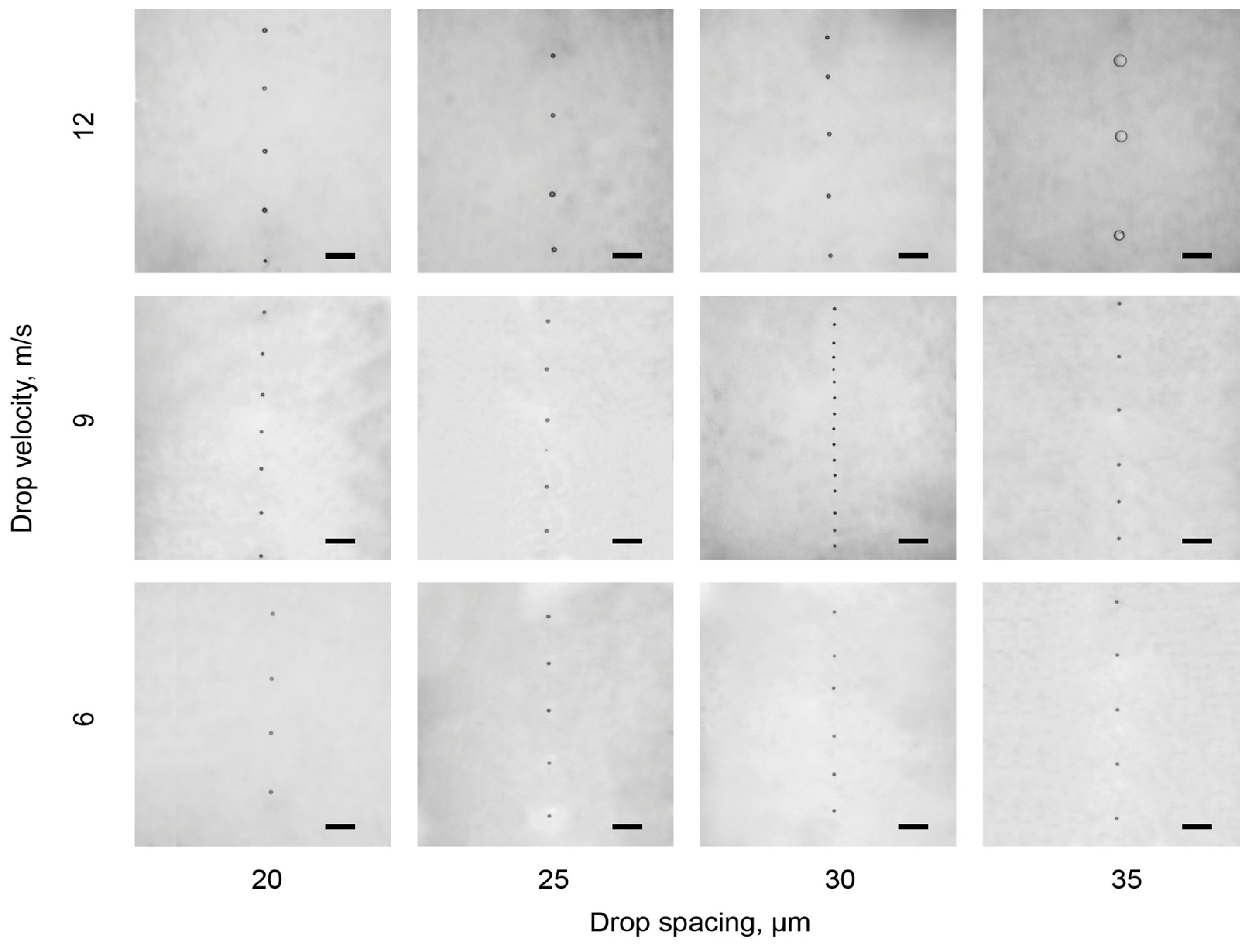
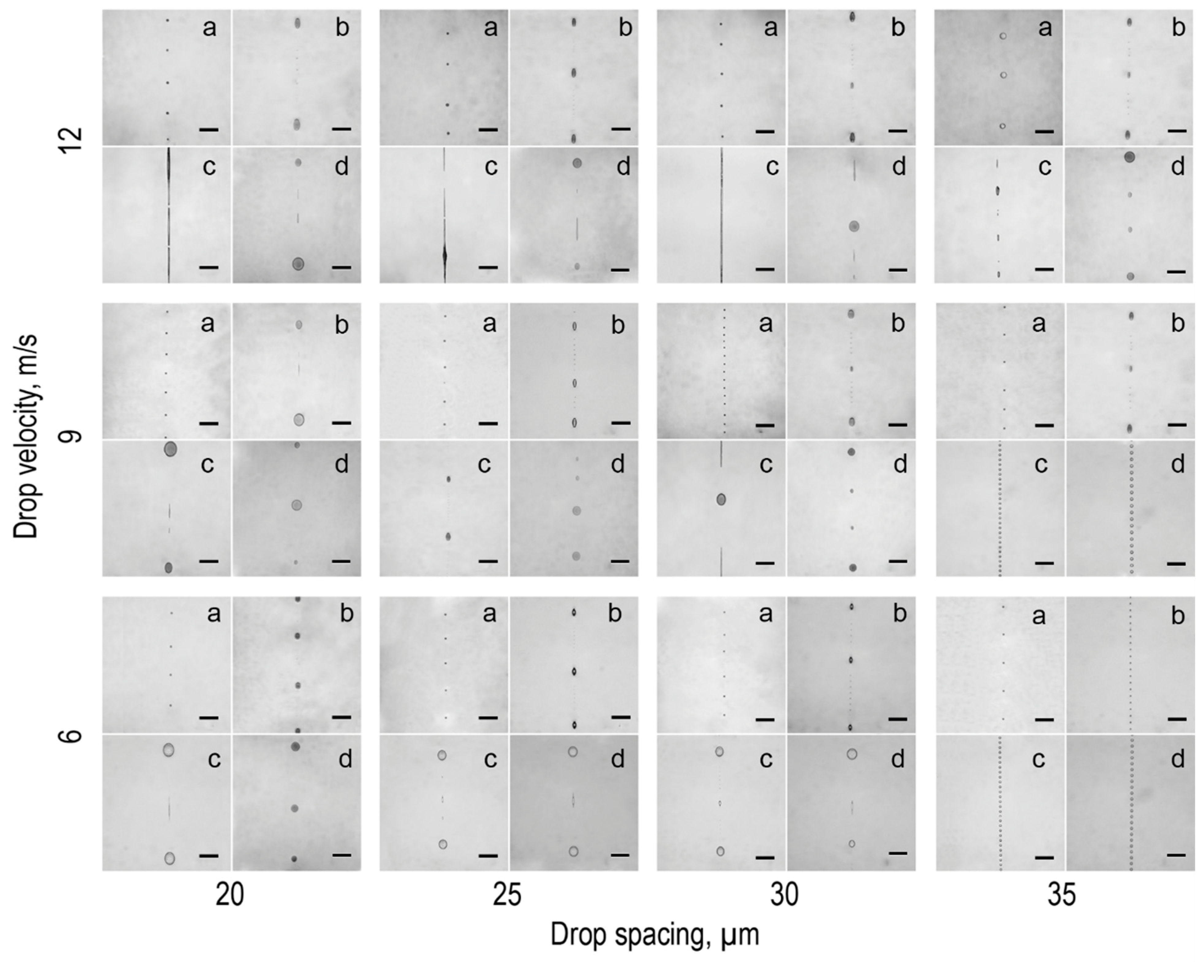
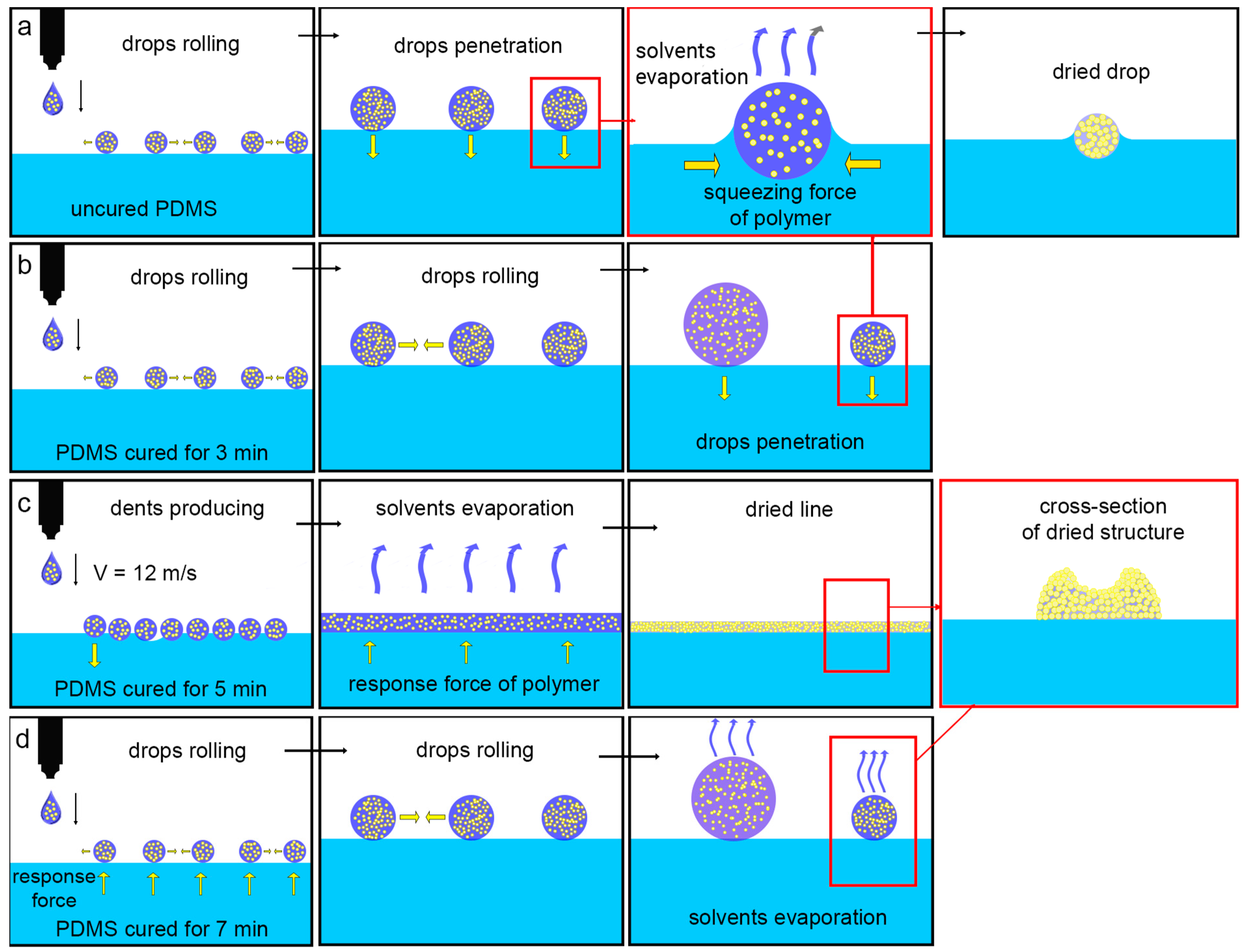
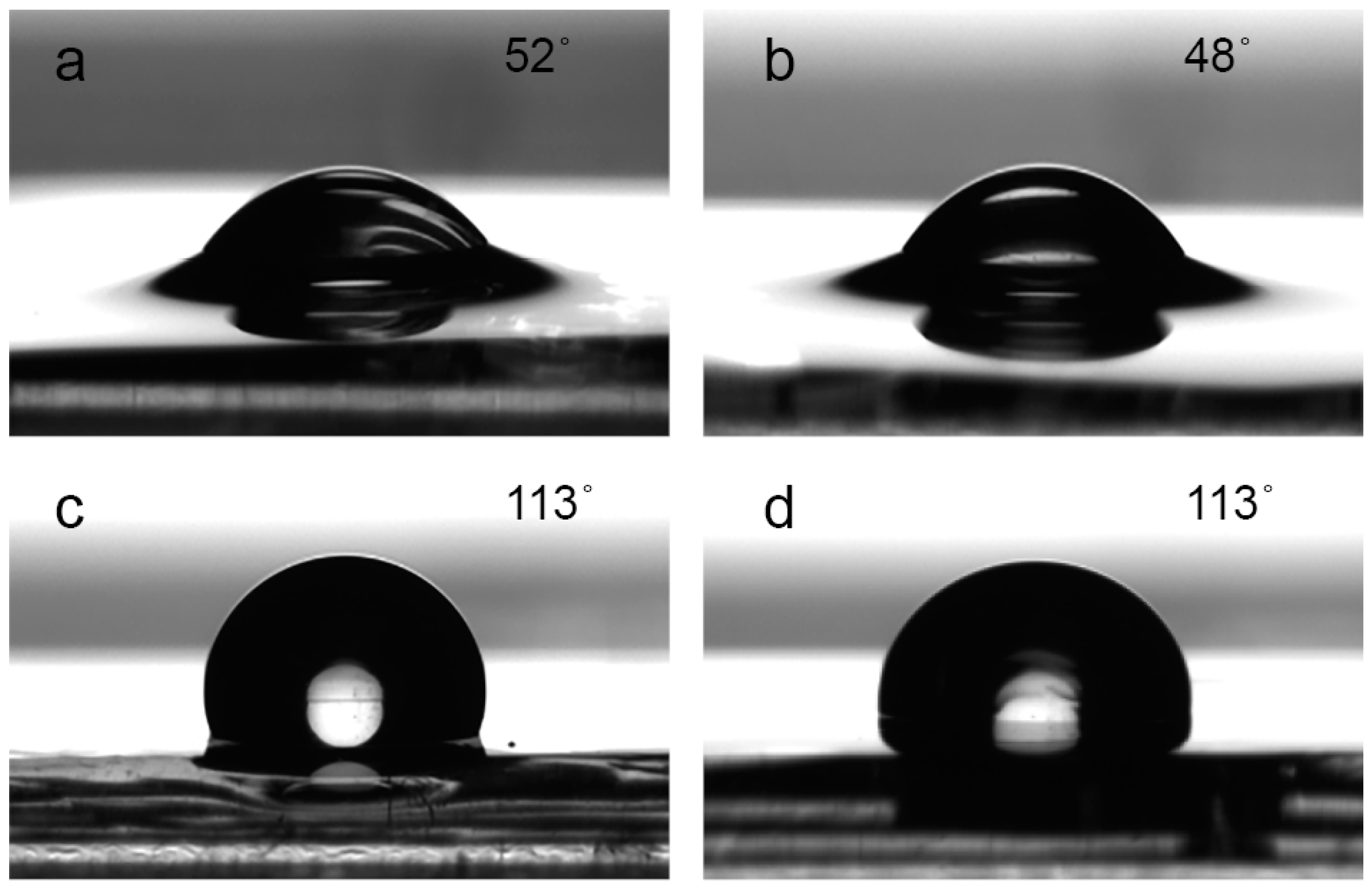
To investigate the interaction of ink drops with an elastomer (PDMS), we printed a 1 pxl line on the elastomer surface varying the drop spacing (parameter ds) from 20 to 35 µm and the drop velocity from 6 to 12 m/s. Our goal was to achieve ink drop coalescence in a straight solid line. As the diameter of the nozzle was 20 microns and the diameter of ink drop was about 40 microns, the decrease of drop spacing led to a more pronounced drop coalescence and the forming of even bigger drops on the elastomeric substrate surface. The impact pressure of the drop impinging on the substrate surface depends on the drop velocity before the impact [31]. The release height as well as the drop release velocity have a direct influence on this parameter. In fact, the desired impact pressure could be equivalently influenced by the drop release height as well as by the drop release velocity. Therefore, in our study we kept the drop release height at a constant value of 450 µm and changed only the drop release velocity. The array of optical images of the 1 pxl line printed on uncured and cured PDMS (for 3, 5, and 7 min at 80 °C) are presented in Figure 2. As we performed inkjet printing in polymeric media, the drop release velocity was expected to be the most essential impact factor. The schematic illustrations of the assumed character of the drop coalescence on the polymer films when cured for different times are presented in Figure 3a–d. PDMS mixed with the curing agent behaved like a viscous liquid (viscosity is 3500 cP). Once the ink drop contacted the polymer film surface, the thin film of the hydrophobic polymer started to wrap the drop surface, preventing the coalescence of neighboring drops (Figure 3a). This effect can also be observed in Figure 4a, which presents the contact angle measurement of ink drops on the uncured PDMS substrate. Since during inkjet printing the volume of the drop is considerably less than the drop volume used for contact angle measurement (10 pL versus 4 µL), we assumed the wrapping ability of the polymer during inkjet printing to be more pronounced. Therefore, once ink drops are covered with a polymer film, the drop coalescence is hindered and the formation of smooth lines becomes impossible. On the other hand, the PDMS is a high-hydrophobic substance and ink drops may roll on the polymer surface because of their low volume and weight until the drop coalescence occurs. The time of this process is not constant and therefore the distance between the coalescent drops on the substrate can be different. This assumption can explain the fluctuations in coalescent drops by constantly-set drop spacing. From optical images of lines printed on the uncured PDMS given in Figure A1, we can conclude that in the case of uncured PDMS film, the drop velocity plays no critical role in drop coalescence.
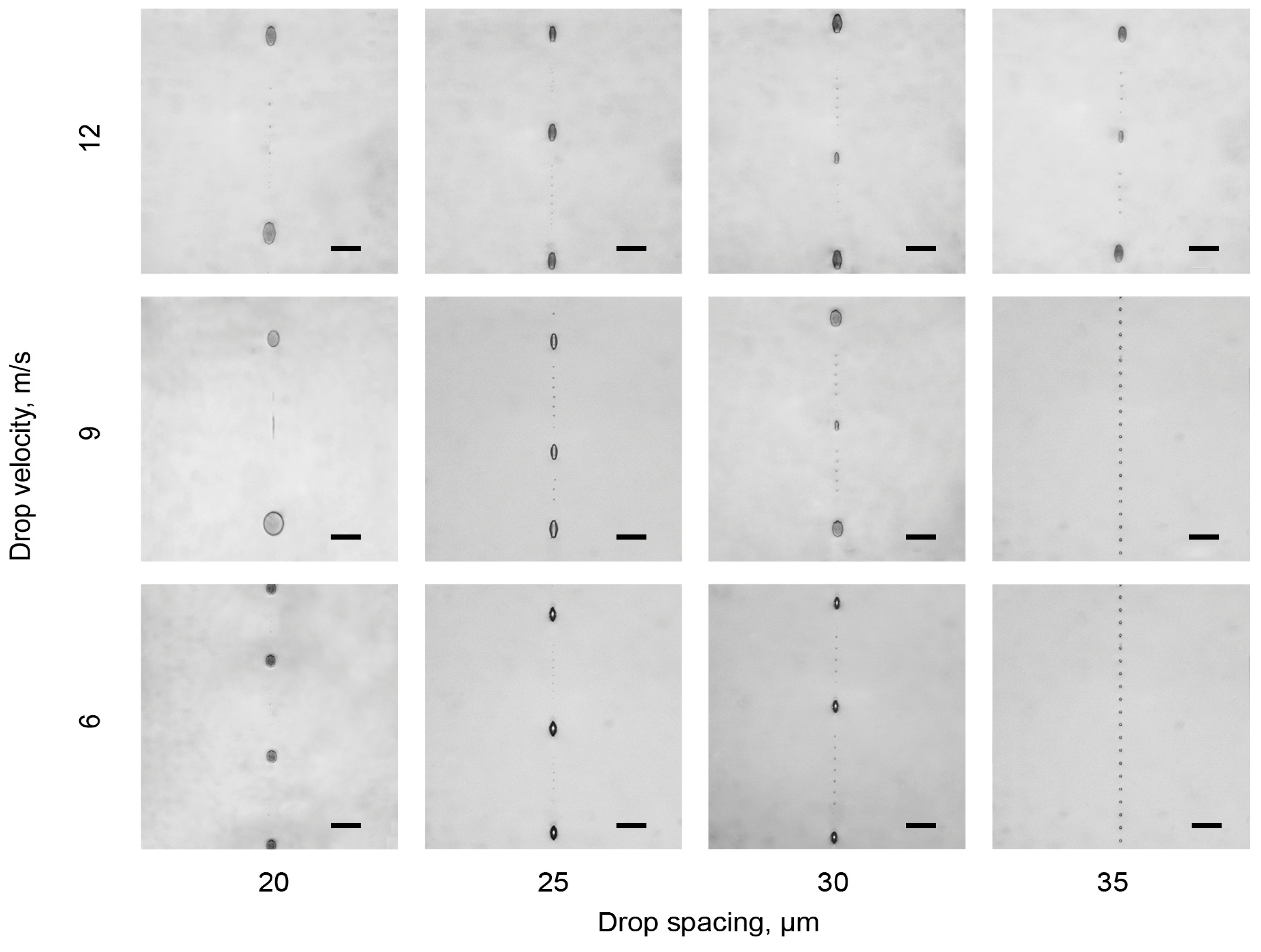
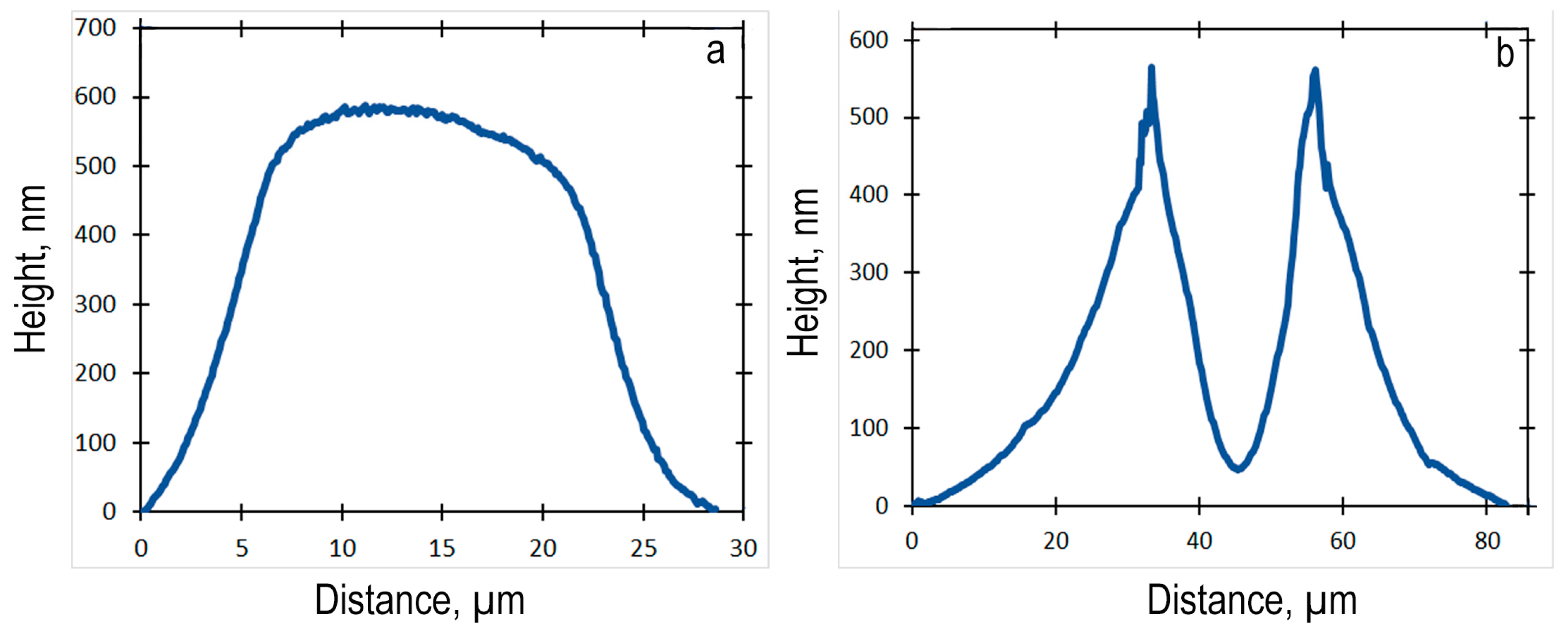
According to the contact angle measurements given in Figure 4a,b, there was no significant difference between PDMS cured for 0 and 3 min. Therefore, the ink drop was also partly wrapped with a thin polymer film. Figure A2 shows that the larger number of printed drops coalesced in one drop on the PDMS surface that was cured for 3 min. This difference can be explained by a higher substrate viscosity and, as a consequence, a higher reaction force that prevented the drop penetration into the polymer volume and thus the wrapping of ink drops. The printed drops were able to freely “roll” on the polymer surface and coalesce into larger ink drops. The ellipsoid shape of the big drops indicated that there is a squeezing force of the polymer surface that prevents the formation of ideally-spherical drops. This squeezing force can be confirmed by the absence of the “coffee-ring” effect. This was proven by the topography of the printed drop obtained by an AFM (atomic force microscopy) method (refer to Figure 5a). The “coffee-ring” effect takes place because of the differential solvent evaporation rates across the drop and the resulting Marangoni flow inside the drop, leading to particles transferring to the drop edges [28]. As a result, the density of the solid–state distribution in the center of the dried drops was lower than at the edges. The squeezing force in the polymer volume led to a close packing of nanoparticles and therefore, to the absence of the “coffee-ring” effect. Moreover, in the study [29], the presence of a horizontal squeezing force in a liquid PDMS precursor was proven by changing the concentration of the solid state in the ink and observing the cross-section of printed lines. Figure 3b schematically shows these sequential processes. In this case, the influence of the drop velocity was more pronounced for the drop spacing of 35 µm.
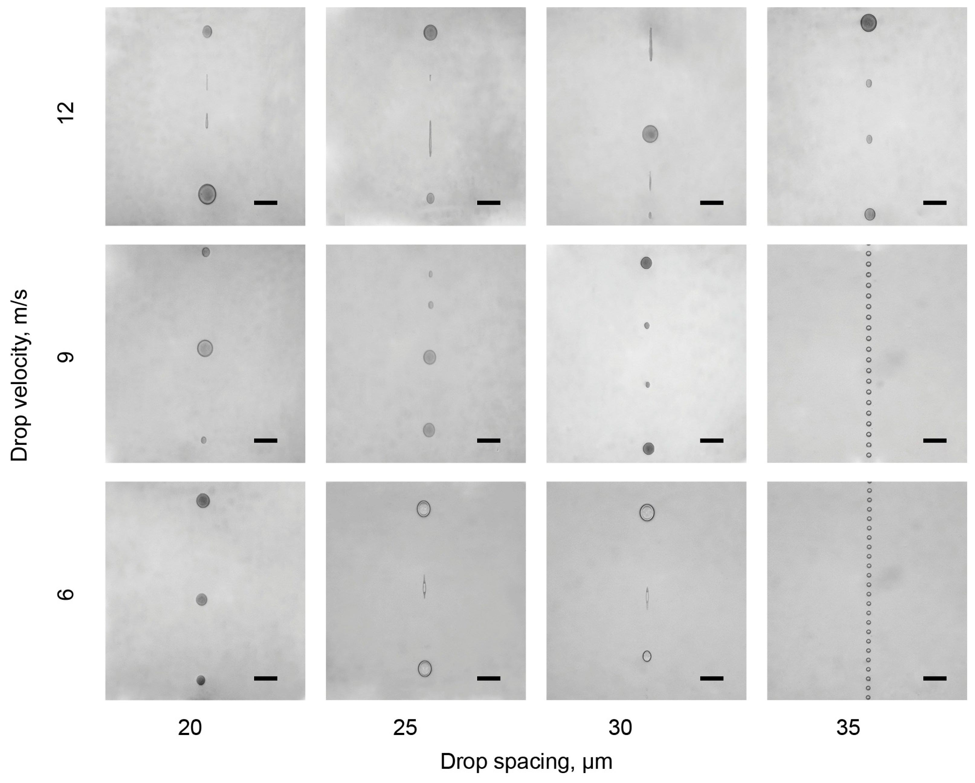
The results of the contact angle measurements showed that for 5 and 7 min of PDMS curing, no penetration into the polymer volume was observed. In this case, printing on a hydrophobic elastic surface was performed. The diameter of the coalescent drops in Figure A3 and Figure A4 was larger than in Figure A1 and Figure A3. Additionally, they had a spherical shape. This can be explained by the fact that already-cured polymer does not wrap drops that are deposited on a substrate surface. Thus there was no compression force, as in this case the PDMS was a solid film. This fact can also be confirmed by the cross-sectional topography of the line printed on PDMS that was cured for 5 min and obtained by AFM with a strongly pronounced “coffee-ring” effect (Figure 5b).
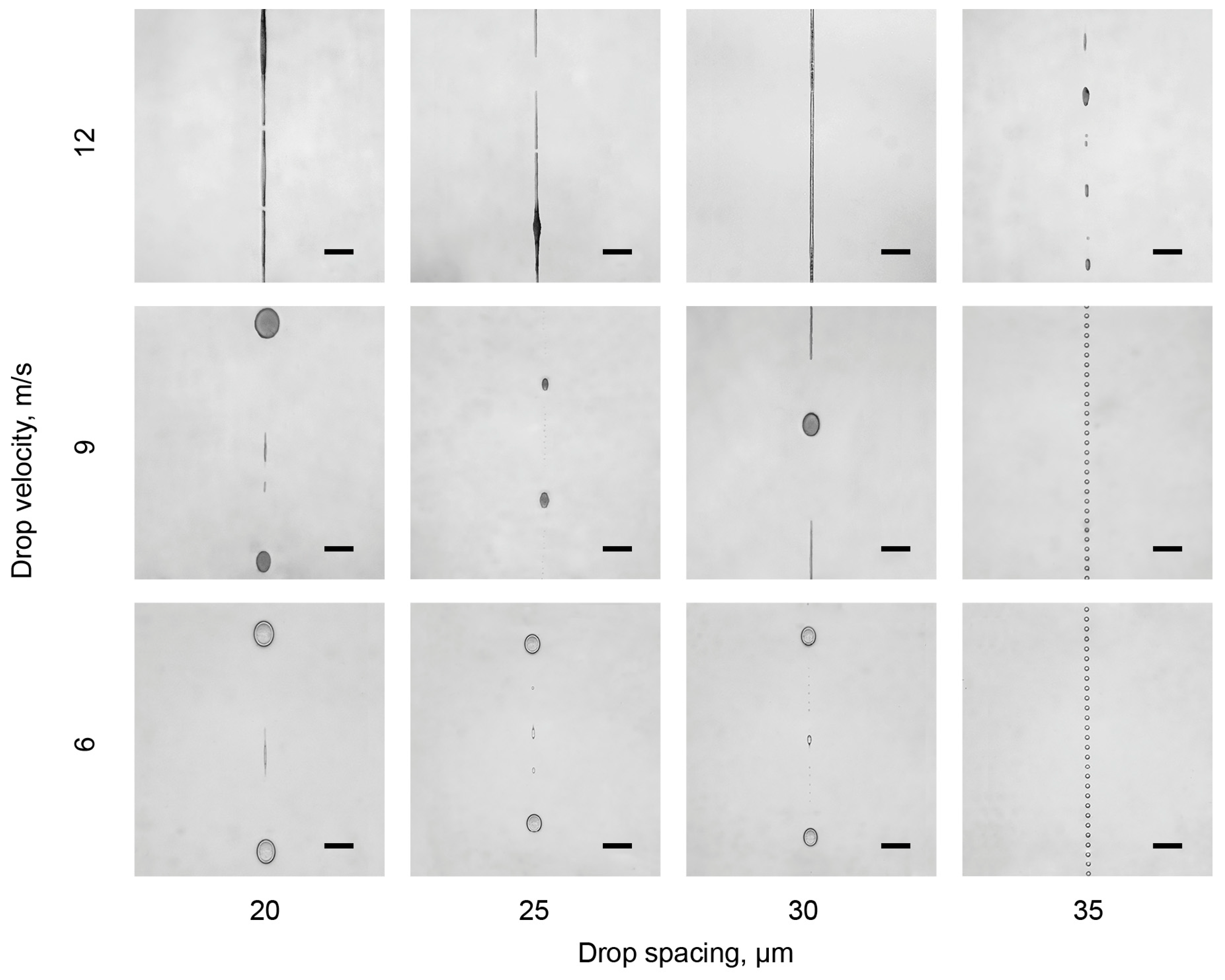
The schematic illustrations of the character of the drop coalescence on the polymer films when cured for 5 and 7 min are presented in Figure 3c,d, respectively. When PDMS was cured for 5 min at 80 °C (Figure A3), the drop velocity during printing on this film had a great influence on drop coalescence. Only in the case of a high drop speed (>10 m/s) was it possible to print a smooth line. We assumed that drops with high velocity press the substrate polymer (water hammer effect [31]), produce a dent, and stay in it until the drops coalesce. When PDMS was cured for 7 min, there was no influence of drop velocity as its surface was fully polymerized and was not soft enough to deform under the imposed impact force. In this case, the ink drops roll freely on the polymer surface and coalesce to larger drops.

4. Discussion

Inkjet printing as a widespread technique for the deposition of a variety of materials at the nano- and microscales was used in this work. We chose PDMS as it is often used as a flexible polymeric substrate due to its special mechanical and optical properties. This study fills an existing gap in the research into the coalescence of ink drops printed on PDMS film depending on the viscosity of the polymer substrate and printing parameters such as drop spacing and drop release velocity.
In this extensive experimental study, we have demonstrated the inkjet printing on PDMS films with various viscosities, which was controlled by curing time. PDMS films cured for 0 or 3 min were still liquid and had the ability to wrap the ink drops. The data obtained have shown that for such substrate viscosity, drop velocity plays no crucial role in drop coalescence. For such a system, the drop spacing and ability of drops to roll on the polymer surface are the most important factors. For these PDMS film states, the formation of uniform solid lines could not be achieved.
The most interesting and appropriate results were obtained for PDMS films that were cured for 5 min as they had an intermediate state between liquid and solid. Due to this special viscous state, drop velocity had a great influence on drop coalescence. For this PDMS state, the formation of uniform solid lines could be achieved by using these optimal printing parameters: drop spacing of 30 µm and drop velocity of 12 m/s. Resulting from the drop arrangement on the polymer surface and the appearance of the “coffee-ring” effect, inkjet printing on PDMS when cured for 7 min was similar to printing on a highly hydrophobic substrate as it was already in a solid state. In this case, the formation of a uniform solid line was not achieved.
The obtained results are useful for future investigations in the field of intra-volumetric printing and are beneficial for the transfer of technological know-how and arousing a general interest in additive technologies among the scientific community. The printed structures can be important for the development of flexible electronic and integrated optical circuits. Further studies will be devoted to the examination of dependence and the improvement of drop coalescence and penetration depth on ink composition.

Author Contributions

Conceptualization, A.K. and A.V.V.; Investigation, A.K.; Supervision, E.S. and A.V.V.; Visualization, A.K.; Writing—original draft, A.K.; Writing—review and editing, E.S. and A.V.V.

Funding

This work was supported by the Russian Science Foundation (No. 16-19-10346).

Conflicts of Interest

The authors declare no conflict of interest. The founding sponsors had no role in the design of the study, in the collection, analyses, or interpretation of data, in the writing of the manuscript, or in the decision to publish the results.

Appendix A

Figure A1. Array of optical images of a 1 pxl line printed on uncured PDMS as a function of drop spacing and velocity. The scale bar is 100 µm.
Coatings 09 00275 g0a1
Figure A2. Array of optical images of a 1 pxl line printed on PDMS when cured for 3 min at 80 °C depending on drop spacing and velocity. The scale bar is 100 µm.
Coatings 09 00275 g0a2
Figure A3. Array of optical images of a 1 pxl line printed on PDMS when cured for 5 min at 80 °C depending on drop spacing and velocity. The scale bar is 100 µm.
Coatings 09 00275 g0a3
Figure A4. Array of optical images of a 1 pxl line printed on PDMS when cured for 7 min at 80 °C depending on drop spacing and velocity. The scale bar is 100 µm.
Coatings 09 00275 g0a4

References

  1. Secor, E.B.; Prabhumirashi, P.L.; Puntambekar, K.; Geier, M.L.; Hersam, M.C. Inkjet Printing of High Conductivity, Flexible Graphene Patterns. J. Phys. Chem. Lett. 2013, 4, 1347–1351. [Google Scholar] [CrossRef]
  2. Van Osch, T.H.J.; Perelaer, J.; de Laat, A.W.M.; Schubert, U.S. Inkjet printing of narrow conductive tracks on untreated polymeric substrates. Adv. Mater. 2008, 20, 343–345. [Google Scholar] [CrossRef]
  3. Huang, D.; Liao, F.; Molesa, S.; Redinger, D.; Subramanian, V. Plastic-compatible low resistance printable gold nanoparticle conductors for flexible electronics. J. Electrochem. Soc. 2003, 150, G412. [Google Scholar] [CrossRef]
  4. Sun, Y.; Rogers, J.A. inorganic semiconductors for flexible electronics. Adv. Mater. 2007, 19, 1897–1916. [Google Scholar] [CrossRef]
  5. Hong, S.; Myung, S. A flexible approach to mobility: Nanotube Electronics. Nat. Nanotechnol. 2007, 2, 207–208. [Google Scholar] [CrossRef] [PubMed]
  6. Mativenga, M.; Choi, M.H.; Choi, J.W.; Jang, J. Transparent flexible circuits based on amorphous-indium–gallium–zinc–oxide thin-film transistors. IEEE Electron Device Lett. 2011, 32, 170–172. [Google Scholar] [CrossRef]
  7. Chen, Y.; Au, J.; Kazlas, P.; Ritenour, A.; Gates, H.; McCreary, M. Flexible active-matrix electronic ink display: Electronic paper. Nature 2003, 423, 136. [Google Scholar] [CrossRef]
  8. Pagliaro, M.; Ciriminna, R.; Palmisano, G. Flexible solar cells. ChemSusChem 2008, 1, 880–891. [Google Scholar] [CrossRef]
  9. Ichikawa, Y.; Yoshida, T.; Hama, T.; Sakai, H.; Harashima, K. Production technology for amorphous silicon-based flexible solar cells. Sol. Energy Mater. Sol. Cells 2001, 66, 107–115. [Google Scholar] [CrossRef]
  10. Axisa, F.; Gehin, C.; Delhomme, G.; Collet, C.; Robin, O.; Dittmar, A. Wrist ambulatory monitoring system and smart glove for real time emotional, sensorial and physiological analysis. In Proceedings of the 26th Annual International Conference of the IEEE Engineering in Medicine and Biology Society IEEE, San Francisco, CA, USA, 1–5 September 2004; Volume 3, pp. 2161–2164. [Google Scholar]
  11. Axisa, F.; Schmitt, P.M.; Gehin, C.; Delhomme, G.; McAdams, E.; Dittmar, A. flexible technologies and smart clothing for citizen medicine, home healthcare, and disease prevention. IEEE Trans. Inf. Technol. Biomed. 2005, 9, 325–336. [Google Scholar] [CrossRef] [PubMed]
  12. Allen, A.C.; Sunden, E.; Cannon, A.; Graham, S.; King, W. Nanomaterial transfer using hot embossing for flexible electronic devices. Appl. Phys. Lett. 2006, 88, 083112. [Google Scholar] [CrossRef]
  13. Peng, L.; Deng, Y.; Yi, P.; Lai, X. Micro hot embossing of thermoplastic polymers: A review. J. Micromech. Microeng. 2014, 24, 013001. [Google Scholar] [CrossRef]
  14. Paeng, D.; Yoo, J.-H.; Yeo, J.; Lee, D.; Kim, E.; Ko, S.H.; Grigoropoulos, C.P. Low-cost facile fabrication of flexible transparent copper electrodes by nanosecond laser ablation. Adv. Mater. 2015, 27, 2762–2767. [Google Scholar] [CrossRef]
  15. Hou, J.; Chen, Y.; Li, Y.-S.; Weng, X.; Li, H.; Pereira, C. 32.3: Reliability and performance of flexible electrophoretic displays by roll-to-roll manufacturing processes. SID Symp. Dig. Tech. Pap. 2004, 35, 1066. [Google Scholar] [CrossRef]
  16. Krebs, F.C.; Gevorgyan, S.A.; Alstrup, J. A roll-to-roll process to flexible polymer solar cells: model studies, manufacture and operational stability studies. J. Mater. Chem. 2009, 19, 5442. [Google Scholar] [CrossRef]
  17. Allen, K.J. Reel to real: Prospects for flexible displays. Proc. IEEE 2005, 93, 1394–1399. [Google Scholar] [CrossRef]
  18. Moonen, P.F.; Yakimets, I.; Huskens, J. Fabrication of transistors on flexible substrates: from mass-printing to high-resolution alternative lithography strategies. Adv. Mater. 2012, 24, 5526–5541. [Google Scholar] [CrossRef]
  19. Gomez De Arco, L.; Zhang, Y.; Schlenker, C.W.; Ryu, K.; Thompson, M.E.; Zhou, C. Continuous, highly flexible, and transparent graphene films by chemical vapor deposition for organic photovoltaics. ACS Nano 2010, 4, 2865–2873. [Google Scholar] [CrossRef]
  20. Derby, B. Inkjet printing of functional and structural materials: fluid property requirements, feature stability, and resolution. Annu. Rev. Mater. Res. 2010, 40, 395–414. [Google Scholar] [CrossRef]
  21. Sirringhaus, H.; Kawase, T.; Friend, R.H.; Shimoda, T.; Inbasekaran, M.; Wu, W.; Woo, E.P. High-resolution inkjet printing of all-polymer transistor circuits. Science 2000, 290, 2123–2126. [Google Scholar] [CrossRef]
  22. Hoath, D.S. Fundamentals of Inkjet Printing: The Science of Inkjet and Droplets, 1st ed.; Wiley-VCH: Weinheim, Germany, 2016; ISBN 978-3-527-33785-9. [Google Scholar]
  23. Sun, J.; Guo, Y.; Cui, B.; Chu, F.; Li, H.; Li, Y.; He, M.; Ding, D.; Liu, R.; Li, L.; et al. Inkjet printing bendable circuits based on an oil-water interface reaction. Appl. Surf. Sci. 2018, 445, 391–397. [Google Scholar] [CrossRef]
  24. Soltman, D.; Subramanian, V. Inkjet-printed line morphologies and temperature control of the coffee ring effect. Langmuir 2008, 24, 2224–2231. [Google Scholar] [CrossRef] [PubMed]
  25. Stringer, J.; Derby, B. Formation and stability of lines produced by inkjet printing. Langmuir 2010, 26, 10365–10372. [Google Scholar] [CrossRef] [PubMed]
  26. Kang, B.J.; Oh, J.H. Geometrical characterization of inkjet-printed conductive lines of nanosilver suspensions on a polymer substrate. Thin Solid Films 2010, 518, 2890–2896. [Google Scholar] [CrossRef]
  27. Kawase, T.; Shimoda, T.; Newsome, C.; Sirringhaus, H.; Friend, R.H. Inkjet printing of polymer thin film transistors. Thin Solid Films 2003, 438–439, 279–287. [Google Scholar] [CrossRef]
  28. Singh, M.; Haverinen, H.M.; Dhagat, P.; Jabbour, G.E. Inkjet printing-process and its applications. Adv. Mater. 2010, 22, 673–685. [Google Scholar] [CrossRef] [PubMed]
  29. Jiang, J.; Bao, B.; Li, M.; Sun, J.; Zhang, C.; Li, Y.; Li, F.; Yao, X.; Song, Y. fabrication of transparent multilayer circuits by inkjet printing. Adv. Mater. 2016, 28, 1420–1426. [Google Scholar] [CrossRef]
  30. Jang, D.; Kim, D.; Moon, J. Influence of fluid physical properties on ink-jet printability. Langmuir 2009, 25, 2629–2635. [Google Scholar] [CrossRef] [PubMed]
  31. Deng, T.; Varanasi, K.K.; Hsu, M.; Bhate, N.; Keimel, C.; Stein, J.; Blohm, M. Nonwetting of impinging droplets on textured surfaces. Appl. Phys. Lett. 2009, 94, 133109. [Google Scholar] [CrossRef]
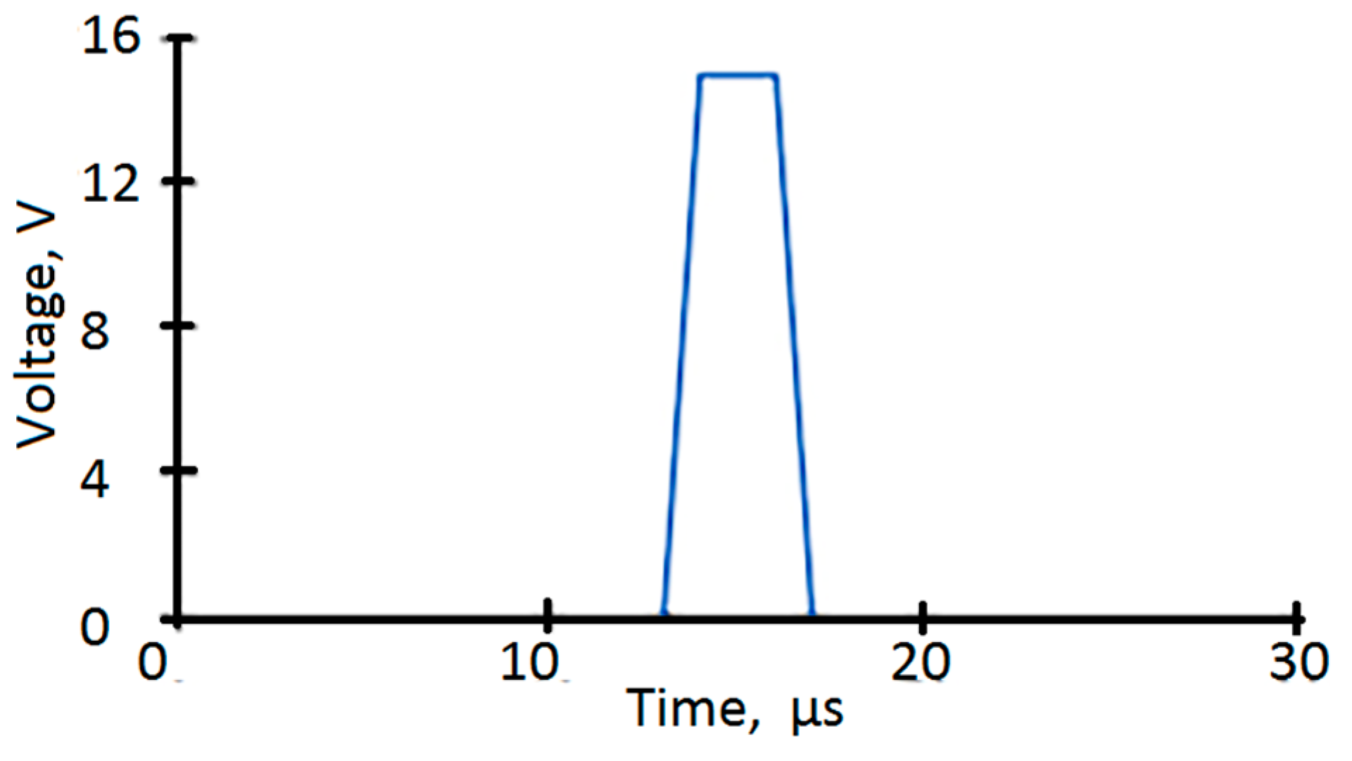
Figure 1. The waveform used for intra-volumetric printing.
Coatings 09 00275 g001
Figure 2. Array of optical images of a 1 pxl line printed on poly(dimethylsiloxane) (PDMS) (a) uncured, (b) cured for 3 min, (c) cured for 5 min, and (d) cured for 7 min, all at 80 °C as a function of drop spacing and release velocity. The scale bar is 100 µm.
Coatings 09 00275 g002
Figure 3. Schematic illustration of ink drops behavior printed on PDMS films cured for (a) 0, (b) 3, (c) 5, and (d) 7 min.
Coatings 09 00275 g003
Figure 4. The contact angle of ink drops on PDMS surface cured for (a) 0, (b) 3, (c) 5, and (d) 7 min.
Coatings 09 00275 g004
Figure 5. The AFM obtained cross-sections of (a) a drop printed on PDMS substrates cured for 3 min at 80 °C and (b) a line printed on PDMS precured for 5 min at 80 °C. Semi-contact mode was used for the AFM measurement.
Coatings 09 00275 g005