1. Introduction
At present, a new scientific direction devoted to the theoretical and experimental study of hybrid materials based on two-dimensional (2D) graphene and one-dimensional (1D) carbon nanotubes (CNTs) exists in materials science [
1,
2,
3,
4,
5,
6]. Research teams from different countries proposed several structural varieties of this hybrid material, differing in the method of joining CNTs and graphene, as well as their mutual orientation [
7]. Three-dimensional (3D) composites (pillared graphene) with a vertical orientation of CNTs spliced with graphene structures [
8,
9,
10,
11,
12,
13,
14,
15,
16,
17], and 2D films with a horizontal orientation of CNTs, which are connected to graphene through several covalent bonds or interact with it through van der Waals forces [
17,
18,
19,
20], are of prime interest to researchers. The reason for the increased attention of scientists to these hybrid structures is their unusually wide range of applications and an improved palette of properties as compared to conventional carbon materials due to the synergistic effect of CNTs and graphene. The first results of a study of novel carbon composite structures showed their superiority over individual nanotubes and graphene in electrical, optical, and electrochemical properties, providing new ways for developing promising practical applications based on these materials. In particular, the excellent electrochemical properties of pillared graphene led to its wide application as an electrode for batteries and supercapacitors [
8,
9,
10,
11]. The pillared graphene-based supercapacitors demonstrate a capacitance retention of 98% over 30,000 charge–discharge cycles, while maintaining excellent cyclic stability and electrochemical reversibility [
8]. In addition, pillared graphene is promising as a hydrogen storage system [
12] and methane storage system [
13], as membranes for gas separation [
14], as thermal interface materials for high-performance cooling applications [
15], and as the element base of phonon devices [
16] and nanomechanical sensors [
17].
Two-dimensional graphene–CNT composite films with horizontally oriented CNTs are also in high demand as multifunctional materials. Modern synthesis technologies allow us to obtain graphene–CNT hybrid films with both ordered and unordered arrangement of multi-walled CNTs (MWCNTs) or single-walled CNT (SWCNTs) connected to graphene through covalent bonds [
18,
19,
20,
21,
22,
23,
24,
25] or through van der Waals forces [
26,
27,
28]. At the same time, hybrid films with CNTs located on graphene [
29,
30,
31,
32], and hybrid films with CNTs covered with graphene on top [
33,
34,
35,
36] are distinguished. The diversity in the architecture of graphene–CNT hybrid films results in their wide range of applications.
Due to their improved electrochemical properties, graphene–CNT composite films CNTs and reduced graphene oxide coupled through van der Waals are considered as high-performance negative electrodes in asymmetric supercapacitors [
37]. It was found that intercalating a small amount of CNTs between reduced graphene oxide sheets led to excellent specific capacitance of 272 F·g
−1 at a scan rate of 5 mV·s
−1 in a negative potential window from −0.8 to 0 V. The coating of such a composite structure with cobalt hydroxide allows us to further increase the specific capacity of the graphene oxide–CNT composite film-based asymmetric supercapacitor up to 310 F·g
−1 [
38]. Composite films based on a CNT layer coated with a graphene layer are promising materials for photovoltaics. As shown by Maarouf et al. [
36], the hybrid films with a graphene monolayer deposited on a monolayer of self-assembled conducting SWCNTs had a transparency of 97% in the visible wavelength range. Kholmanov et al. [
33] obtained hybrid films from a graphene monolayer deposited on a layer of ordered MWCNTs that showed strong anisotropy in optical transparency depending on the direction of polarization of the electromagnetic wave. In particular, when the electromagnetic wave was polarized parallel to the direction of CNT orientation, the transparency of hybrid films was 75%–80% in the wavelength range from 400 to 1400 nm. When the electromagnetic wave was polarized perpendicular to the direction of CNT orientation, the transparency of hybrid films was 87%–93% in the same wavelength range.
Composite films with a covalent compound of CNT and graphene are one of the latest structural modifications of graphene–CNT hybrid films. Terrones et al. [
18] developed a self-assembly method for producing hybrid paper-like films consisting of alternating layers of graphene oxide and various types of MWCNTs (pristine and doped with boron and nitrogen). The electrical resistivity of the created films was 3 × 10
−4 Ω·cm, which is significantly less than the resistivity of MWCNT films (0.13 Ω·cm). In addition, these hybrid films can be used as highly efficient electron field emission sources with a threshold electric field of 0.55 V/μm, a field enhancement factor as high as 15.19 × 10
3, and operating currents up to 220 μA. Tour et al. proposed an effective technology for producing transparent and highly conductive graphene–CNT hybrid films by annealing functionalized CNTs on Cu foils [
22]. In this hybrid structure called “rebar graphene”, CNTs act as a reinforcing bar (“rebar”) to improve the mechanical strength and electrical conductivity of the graphene sheets. The rebar graphene sheets demonstrated ~95.8% transmittance at a 550-nm wavelength with a sheet resistance of ~600 Ω/sq, indicating better performance than those of stacked bilayer graphene or CNT films at the same transmittance. A similar graphene–CNT hybrid film was obtained by Kim et al. [
19] using the thermal chemical vapor deposition (CVD) method on a Cu foil coated with CNTs. The resulting film possessed a sheet resistance of 300 Ω/sq with 96.4% transparency. A distinctive feature of these hybrid structures is the alignment of CNTs on graphene, which makes it possible to obtain improved current characteristics of composite films that are promising for the design of field-effect transistors.
One of the main criteria for effectiveness of the use of new composite materials as the elemental base of modern electronics is their ability to withstand certain mechanical loads retaining the electroconductive properties. The preservation of the electroconductive properties of the material during deformation is especially important for devices of flexible and transparent electronics. The mechanical properties of pillared graphene were studied in detail by experimental methods [
39] and computer simulation methods [
40,
41,
42,
43,
44]. For these hybrid carbon structures, the tensile strength at axial stretching and compression was already determined, stress–strain curves were constructed, and Young’s modulus and Poisson’s ratio were estimated. The mechanical properties of composite films based on covalently bonded graphene and horizontally oriented CNTs are currently still unexplored. There are only a few works devoted to the experimental study of the electromechanical properties of hybrid films based on horizontally oriented CNTs covered with a graphene layer, interacting through van der Waals forces [
33,
35]. At the same time, information on the behavior of such hybrid films during deformation and the evaluation of their tensile strength and electrical conductivity are necessary for the development of devices of flexible and tensile electronics with improved characteristics. The purpose of this work was to study the mechanical and electroconductive properties of mono- and bilayer graphene–CNT composite films with horizontal orientation of CNTs using quantum and molecular dynamics modeling.
2. Atomistic Models of Graphene–CNT Composite Films
The super-cells of mono- and bilayer graphene–CNT composite films under study were constructed using an original approach, which we called the “method of magnifying glass” [
45]. The essence of this approach lies in the combined use of molecular-mechanical and quantum-mechanical mathematical models at different stages of modeling in order to obtain the topology of the considered structure as close as possible to the data of a natural experiment. At the initial stage of the “method of magnifying glass”, an atomistic model is constructed as a large fragment of the graphene–CNT composite with a number of atoms of several tens of thousands, and the atomic network of the object is optimized by minimizing its total energy using the molecular dynamics method and the empirical adaptive intermolecular reactive bond order (AIREBO) potential [
46]. At the next stage, a smaller fragment is cut from the middle part of the optimized composite structure, which is re-optimized in a periodic box using the self-consistent charge density functional tight-binding (SCC-DFTB) method [
47]. The dimensions of the box are also optimized to find the configuration that corresponds to minimum total energy. At the final stage, the unit cell is selected from the previous optimized fragment, which is again optimized in the periodic box using the SCC-DFTB method. The optimization parameters in this case are the coordinates of the atoms, and the dimensions of the box.
As shown previously, the most stable monolayer graphene–CNT composite films are formed from semiconductor (10,0) and metal (12,0) CNTs with an inter-tube distance of 8–14 hexagons [
45]. For these atomistic models of the composite film, the heat of formation is in the range from −1.5 to −0.1 kcal/mol·atom. Therefore, in the current work, bilayer composite films were built on the basis of CNTs (10,0) and (12,0). The inter-tube distance was taken in a wide range of 8–16 hexagons. Our research results showed that the inter-tube distance should be an even number of hexagons to obtain a regular structure with the same spacing between CNTs in both layers. This situation is shown in
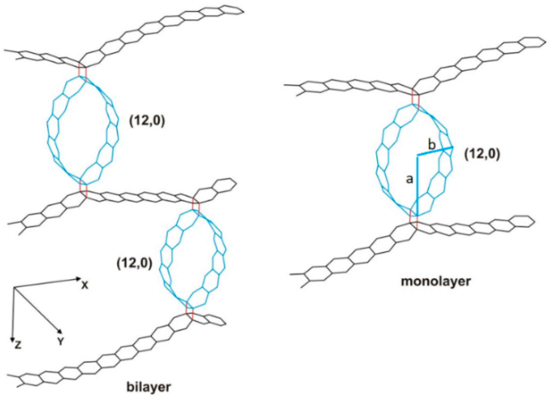
Figure 1, which presents obtained models of composite films based on CNT (12,0) with an inter-tube distance of 12 hexagons. This figure also shows that the middle graphene layer of the bilayer composite film is deformed unlike the other two. The sites of the middle layer enclosed between two adjacent areas of covalent contacts with CNTs (the covalent bonds of graphene–CNT are marked in red) are almost straight. At the same time, the outer graphene layers exhibit an obvious curvilinearity as in the case of a monolayer composite. The geometric and energy parameters of all models of the super-cells of mono- and bilayer composite films based on CNTs (10,0) and (12,0) are presented in
Table 1. This table shows the translation vectors
Lx in the direction of the
X-axis (in the direction perpendicular to the CNT axis), the heat of formation
Hf, the inter-tube distance
rt–t, and the parameter
a/
b characterizing the degree of deformation of CNTs, where
a is the major semi-axis and
b is the minor semi-axis, as shown in
Figure 1. The length of the graphene–CNT covalent bond in all cases is 1.61–1.62 Å. The value of the translation vector
Ly in the direction of the
Y-axis is not given in
Table 1, since it is approximately the same for all super-cells and is equal to 4.27–4.29 Å. Analysis of the characteristics of the constructed super-cells shows that the degree of deformation of CNTs during formation of the composite film is the same for all types of models and is equal to ~1.64–1.66. The heat of formation is negative in all cases. The super-cells of atomistic models with an inter-tube distance of 10 and 12 hexagons are the most energetically favorable for both mono- and bilayer composite films.
3. Deformation of Graphene–CNT Composite Films and Its Effect on Electrical Conductivity: A Mathematical Model
To study the deformation behavior of graphene–CNT composite films, a series of numerical molecular dynamics experiments on the stretching and bending of the considered hybrid carbon structures along different axes were carried out using the SCC-DFTB method to calculate more accurately the object energy during relaxation at each deformation step.
To quantify the mechanical properties of composite films at different stages of deformation, the distribution of local stresses of the atomic network of the structures under study was calculated using the approach proposed by us earlier [
48]. This approach is based on the original idea, according to which the stress per atom of the deformed structure should be evaluated by a change in the energy of the framework atom under external influence. The stress per atom should be understood as the value of the difference between the energy of an atom of a deformed framework and an unloaded (free) framework. This value will reflect the degree of deformation at a given point of the structure, that is, the stress of an atomic network near this atom. The calculation of the local stress was carried out according to the following algorithm:
Optimization of the atomic network of a non-deformed composite film by minimizing its total energy by the coordinates of all atoms using the SCC-DFTB method;
Calculation of the distribution of the bulk energy density over the atoms using the AIREBO potential;
Optimization of the atomic network of the deformed composite film by minimizing its energy by the coordinates of all atoms using the SCC-DFTB method;
Calculation of the distribution of the bulk energy density over the atoms of a structure subjected to an external action using the AIREBO potential;
Calculation of the local stress distribution of the atomic framework from the difference between the values of the bulk energy density of the atoms of the deformed and non-deformed composite film.
The stress per atom with the number
i was calculated as follows:
where
is the bulk energy density of the atom of the composite film before deformation, and
is the bulk energy density of the atom of the composite film after deformation. The bulk energy density of the atom in the framework of the AIREBO potential was calculated as follows:
where
is the interaction energy of covalently bonded atoms, which is determined by the type of atoms and the distance between them;
i and
j are the numbers of interacting atoms;
is the energy of torsion interaction, which is a function of a linear dihedral angle built on the basis of atoms with an edge on the
i–
j bond (atoms forming chemical bonds with atoms
i,
j);
is the van der Waals interaction energy between covalently unbounded atoms;
is the volume occupied by the atom
i; and
r0 is the van der Waals radius of carbon atom, equal to 1.7 Å.
In order to carry out the numerical experiments, we used the DFTB+ software package (version 18.1) [
49], which implements the SCC-DFTB method, and the Kvazar software package (version 2.0) [
50], which implements the molecular dynamics method and the AIREBO potential.
The calculation of the electrical conductivity was carried out in the framework of the Landauer–Buttiker formalism [
51]. This formalism allows us to calculate the electron transmission function and static conductivity. The electron transmission function is determined as follows:
where
,
are the advanced and retarded Green matrices describing contact with the electrodes, and
,
are the broadening matrices for the source and drain. Static conductivity is described as follows:
where
EF is the Fermi energy of the material of the contacts which are connected to the object under study,
e is the electron charge,
h is the Planck constant, and
e2/
h is the conductance quantum. The multiplier (2) takes into account the spin of the electrons.
4. Results and Discussion
The first series of numerical experiments was devoted to a study of the behavior of mono- and bilayer composite films during bending deformation. To carry out calculations, two types of atomistic models of the composite film were constructed from the super-cells shown in
Figure 1, taking into account the direction of bending. The deformation was considered in the direction perpendicular to CNTs, and in the direction along the CNT axis.
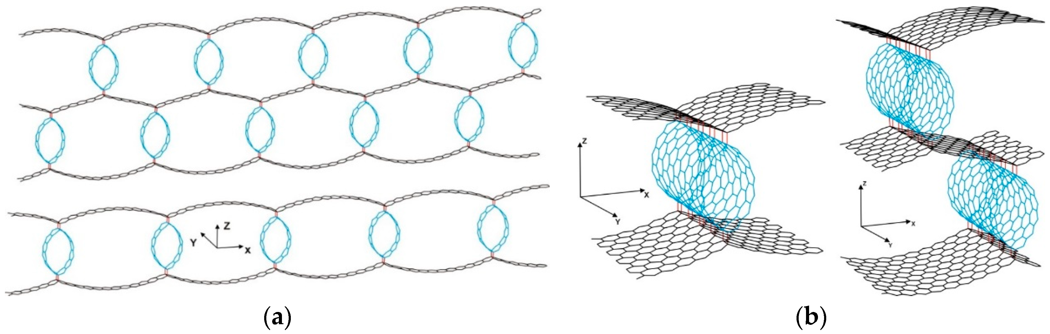
Figure 2 shows atomistic models of mono- and bilayer composite films using the example of a hybrid structure with CNT (12,0) and an inter-tube distance of 12 hexagons. It can be seen from the
Figure 2 that the atomistic model of the composite film in both considered cases of deformation consists of five super-cells which we constructed earlier by means of the method of magnifying glass. In one case, the cell length increases in the direction perpendicular to CNTs (
X-axis), and, in the other case, it increases along the CNT axis (
Y-axis). The number of super-cells in the atomistic model was chosen to minimize the influence of edge effects and to reproduce the deformation behavior of the material adequately from the physical point of view, as well as to take into account the computational features of the SCC-DFTB method used to recalculate the energy at every stage of deformation.
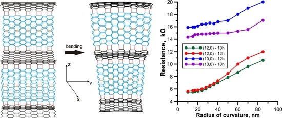
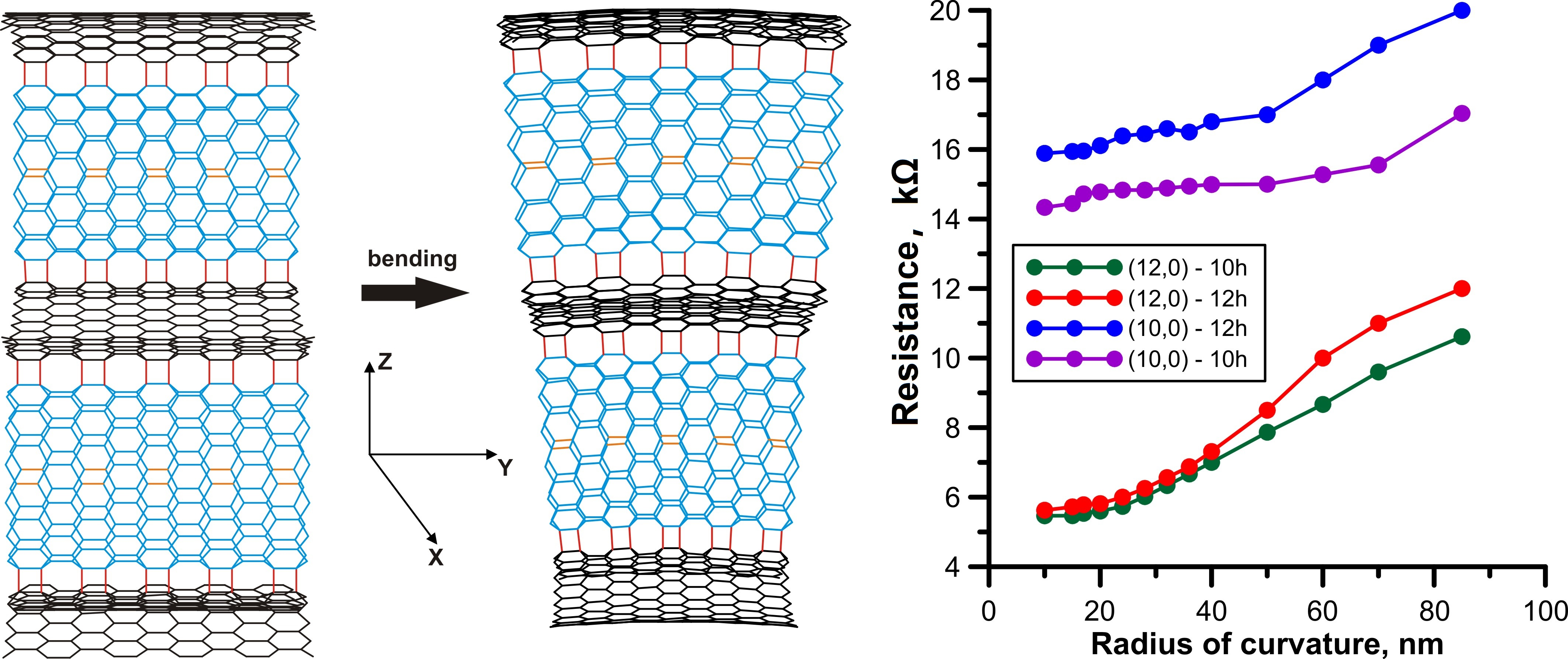
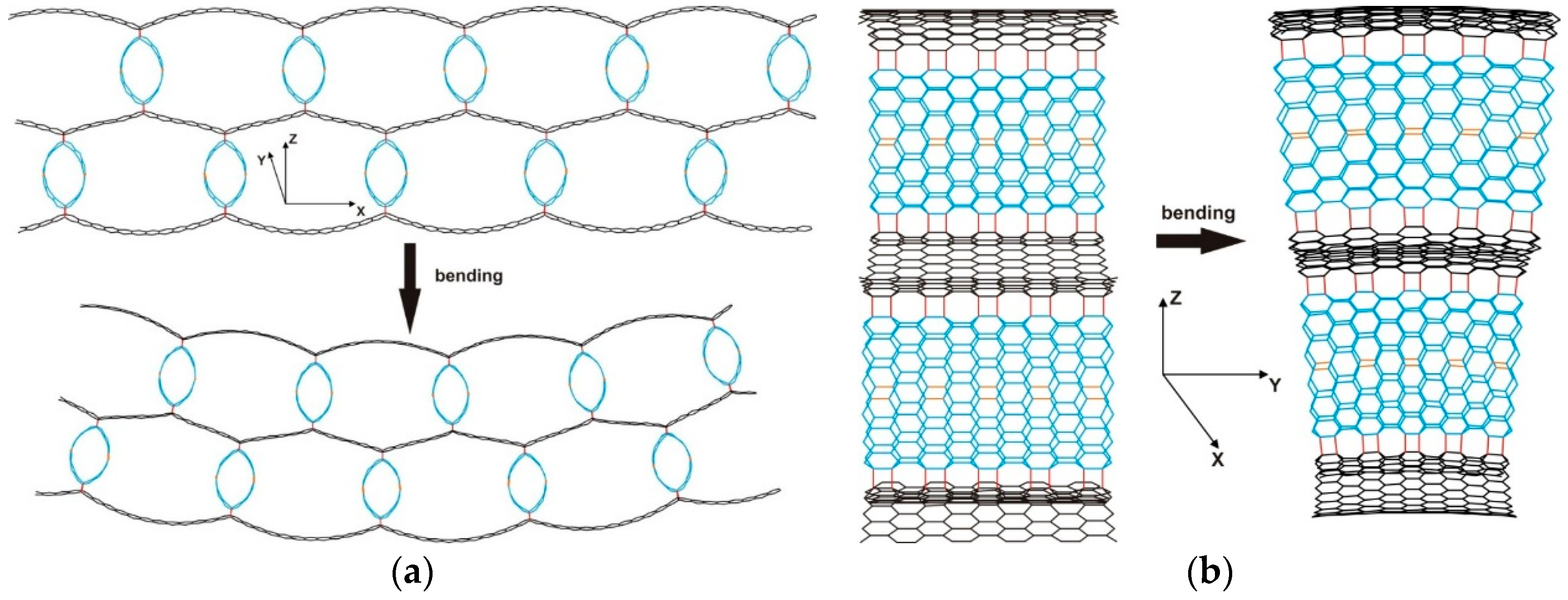
Figure 3 illustrates the scheme of the composite film bending in each of the considered deformation directions using the example of topological models of bilayer composite film with CNT (12,0) and an inter-tube distance of 12 hexagons. In both cases, in order to maintain the atomic network deformation during relaxation of the structure to a minimum of energy, the middle atoms in each of the composite layers were rigidly fixed, forming a neutral layer of atoms not involved in minimizing the object total energy. These atoms are marked in
Figure 3 in orange. A similar scheme of bending and the fixing of atoms was used for monolayer composite films.
Figure 3 shows that, in the case of bending in the direction perpendicular to CNTs (along the
X-axis), the bilayer composite film takes the form of an arc, and, in the case of bending in the direction along the CNT axis (
Y-axis), the upper composite layer stretched along the
Y-axis, and the lower layer compressed along the same axis. This behavior is typical for a beam subjected to bending deformation as a result of an impact of vertical force on its free end, and is described in the framework of the classical beam bending theory. For monolayer composite films, the pattern of deformation behavior was similar to that of the the bilayer composite films. During the study, the bending angle of the composite film along the
X-axis ranged from 0° to 120°, and, along the
Y-axis, it ranged from 0° to 15°. The radius of curvature of the atomic network was changed in the range from 8 to 40 nm for the case of bending along the
X-axis, and in the range from 8 to 81 nm for the case of bending along the
Y-axis.
Using the SCC-DFTB method, the change in the total energy of the composite film at each deformation step was monitored, and relaxation of the atomic network of the structure was carried out. It was found that the composite film structure continued to maintain an arched shape with an increase in the degree of bending along the
X-axis, and only the distance between its ends changed. With an increase in the degree of bending along the
Y-axis, the composite film structure retained a tendency to contraction near the base, while the upper layer of the composite film stretched along the
Y-axis, and the lower layer compressed along the same axis. This behavior is typical for a rod. The degree of bending was estimated from the radius of curvature of the composite film atomic network. According to the results of numerical experiments, we plotted the dependence of the strain energy of the composite film on the radius of curvature of its atomic network. The strain energy was found according to the difference between the total energy of the object before and after bending.
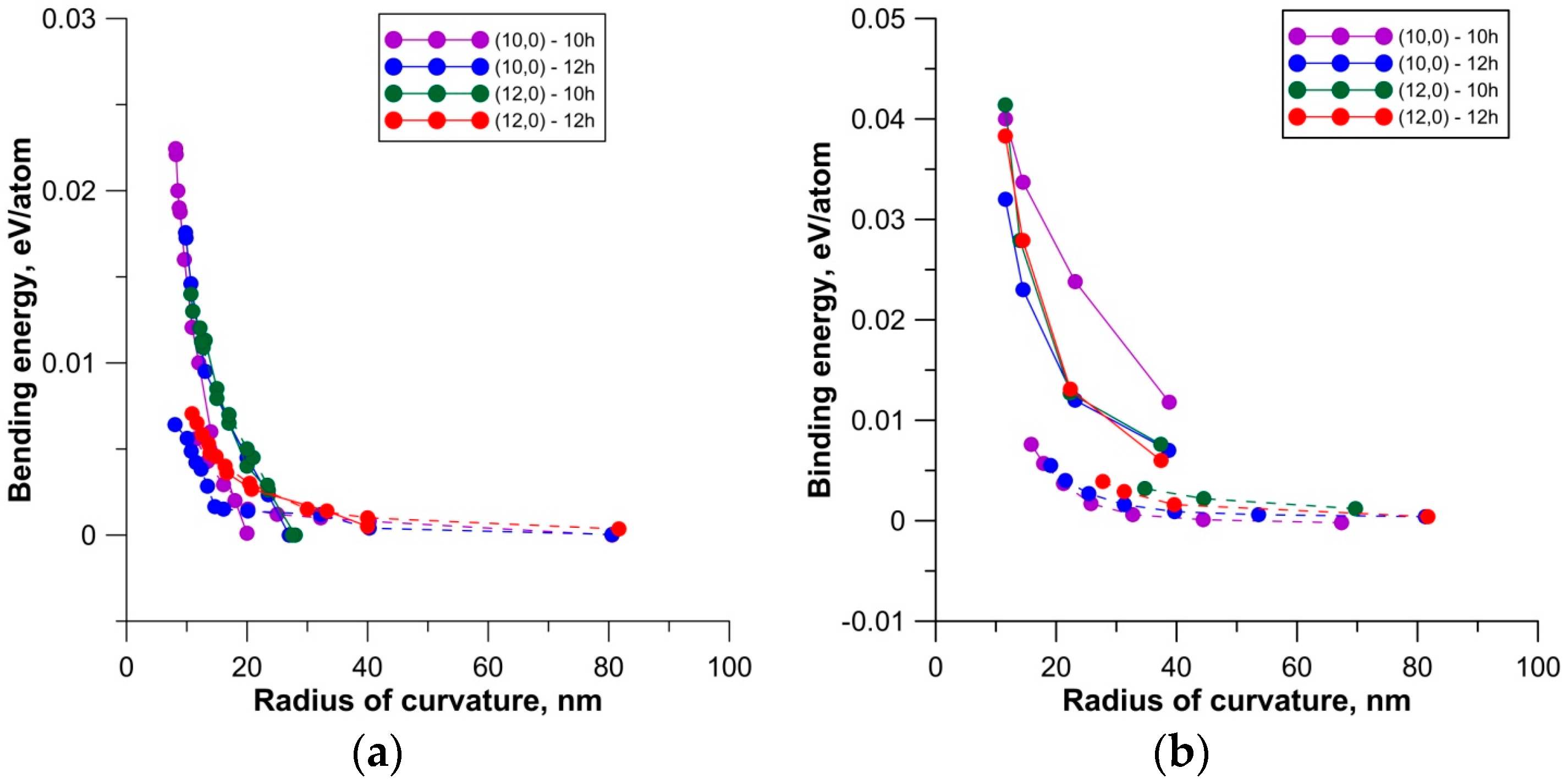
Figure 4 shows the dependences obtained for mono- and bilayer composite films, respectively.
These plots show that the strain energy varied in a similar way in both directions of bending for the monolayer and bilayer composite structures. With an increase in the radius of curvature of the atomic network, the strain energy decreased, indicating that the graphene–CNT composite film adapted to its new geometric shape. The presence of the second layer affected mainly the energy, i.e., it doubled in comparison with the monolayer. Analyzing the course of the dependences presented in
Figure 4, it can be noted that, in the case of bending in the direction perpendicular to CNTs, the strain energy rapidly decreased in a narrow range of variation of the radius of curvature of the composite film atomic network, i.e., in the range of 15–30 nm for monolayer structures, and in the range of 20–40 nm for bilayer structures. A different pattern was observed in the case of the composite bending in the direction along the CNT axis. In this case, the strain energy decreased more slowly and more smoothly, reaching a saturation with the radius of curvature of about 80 nm for both monolayer and bilayer composites. Such a distinction can be due to the fact that the properties of the structural components of composite film manifested differently depending on the direction of deformation; along the
X-axis, the properties of graphene were represented, while, along the
Y-axis, the properties of CNTs were represented. This was also indicated by the structure of the super-cell of the composite film in each of the considered cases of bending. When simulating the bending along the
X-axis, the cell was translated in the direction of the graphene edge, while, when bending along the
Y-axis, it was translated in the direction of the CNT axis. The absence of the sharp energy peaks on the graph suggests that elastic deformation is typical for bent mono- and bilayer composite films. This deformation was accompanied by an exponential decrease in strain energy down to zero as the atomic network of the composite film was curved.
To estimate the energy stability of graphene–CNT composite film during bending deformation in different directions, the local stress distribution of the deformed-structure atomic network was calculated using the algorithm described in
Section 3. Since the deformation behavior of the composite film was estimated by the change in strain energy at the previous stage of the study, the use of the original method based on the energy approach to calculate the local stresses of the atomic network seems justified from a physical point of view. The local stress distribution was calculated for all considered structural models of composite films at the time of ultimate bending in the directions perpendicular to CNTs and along CNTs. The obtained results allowed us to establish the patterns of the local stress distribution for graphene–CNT composite films, regardless of the varied CNT diameter and inter-tube distance, as well as the number of layers.
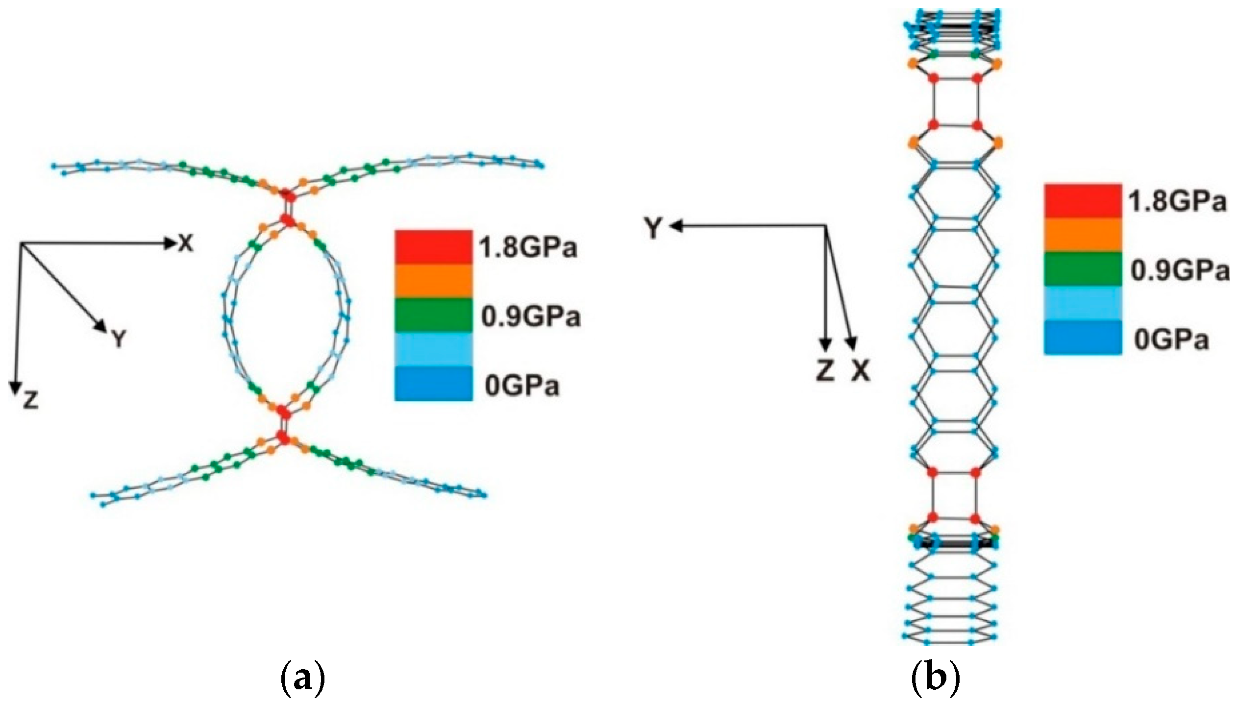
Figure 5 shows the local stress distribution of the composite film atomic network by the example of central fragments of the super-cells of monolayer graphene–CNT structures with CNT (12,0) and an inter-tube distance of 12 hexagons. It can be seen from the figure that, in the cases of bending perpendicular to CNTs and along CNTs, the maximum stresses fell on the atoms forming the covalent bonds between graphene and CNT in the composite film. Covalent bonds between these atoms were broken at the time of ultimate bending deformations for the composite films. The values of the critical stresses experienced by the atoms of the deformed framework were the same for different bending directions and corresponded to the previously established stress value of 1.8 GPa, at which the C–C bond is broken in deformed graphene [
48]. For bilayer composite films, the pattern of stress distribution had a similar outcome as the distribution for monolayer composite films; however, the values of maximum stress decreased slightly for bilayer composites. In general, analyzing the results of the numerical modeling of the deformation behavior of mono- and bilayer composite films during bending, we can note the higher energy stability of graphene–CNT films when bending along the CNT axis.
The second series of numerical experiments was devoted to a study of the behavior of graphene–CNT composite films under stretching. The calculations were carried out for the same super-cells as in the case of bending. During the experiment, the length of the composite film was subsequently increased by 1% at each deformation step. The graphene–CNT structure was retained in the stretched state due to the rigid fixing atoms along the edges of the composite film super-cell and could not return to the initial state. The fixed atoms did not participate in the searching of the equilibrium configuration of the framework corresponding to the ground state. The dependences of the strain energy of the composite film on the strain value in relative units were plotted according to the results of numerical experiments. The strain energy was found by the difference between the total energy of the composite film before and after stretching.
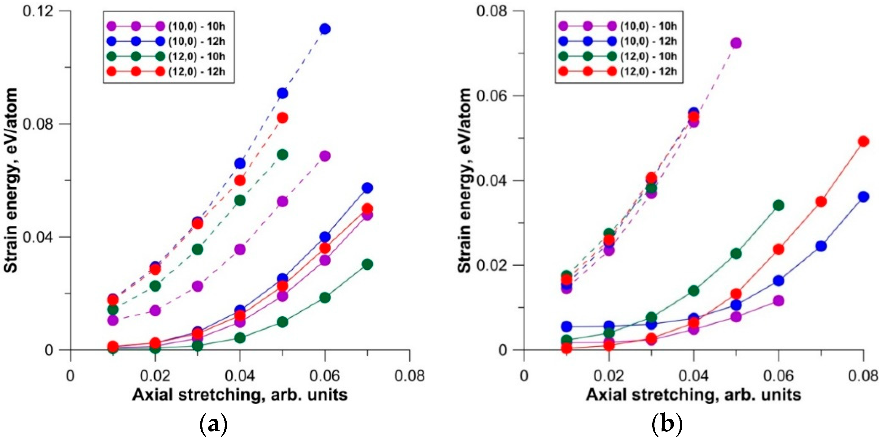
Figure 6 shows the dependences obtained for mono- and bilayer composite films. From the plots presented in the figure, it can be seen that an increase in the strain energy was observed according to a quadratic law for both types of composite films, which corresponds to the elastic deformation of the structure. It should be noted that the graphene–CNT structures under study were more resistant to axial stretching in the longitudinal direction (perpendicular to CNTs). With deformation in the transverse direction (along CNTs), the destruction of the composite film structure occurred faster. This behavior of the composite film can be explained by the topological features of the super-cell types under consideration, i.e., the significant difference in cell lengths in the direction of the stretching graphene–CNT structure. In particular, for mono- and bilayer composite films with CNT (12,0) and an inter-tube distance of 12 hexagons, the length of the super-cell was ~14.5 nm in the direction of deformation perpendicular to CNTs (
X-axis), and ~2 nm in the direction along the CNT axis (
Y-axis).
Analyzing the curves in the graph, one can see that the CNT diameter and inter-tube distance had an impact on the tensile strength of the composite film under axial stretching. In particular, both mono- and bilayer composite films with CNT (12,0) and an inter-tube distance of 10 hexagons offerred the least resistance to tensile strain in the direction along the CNT axis. For monolayer composite films, the destruction of the atomic network occurred at 5% stretching, while that for bilayer composites occurred at 3% stretching. Composite films with tubes (10,0) and an inter-tube distance of 12 hexagons demonstrated the most resistance to tensile deformation along the CNT axis among the studied topological models of mono- and bilayer graphene–CNT hybrid structures. When the composite film was stretched in the direction perpendicular to CNTs, a dependence of the strength properties of the graphene–CNT hybrid structure on the layering was clearly observed. For monolayer composite films, the C–C bond breaking occurred at 7% stretching regardless of the CNT diameter and inter-tube distance. For bilayer composite films, the highest tensile strength was demonstrated by hybrid structures with an inter-tube distance of 12 hexagons. For them, the covalent bond breaking occurred at 8% stretching. The calculation of the local stress distribution showed that the destruction of the atomic network of mono- and bilayer composite films occurred at a critical stress of ~1.8 GPa, regardless of the diameter of the tube and inter-tube distance. This result is in good agreement with the results of computer studies of the deformation of graphene nanoribbons [
48].
As is well known, the stretching of the atomic network of nanostructures does not change their electrical conductivity, since the electronic structure does not change. The electrical conductivity value will also change dramatically at the moment of the breaking of interatomic bonds. A completely different situation occurs in the case of the bending. During the bending of nanostructures, the electron clouds of atoms are re-hybridized; therefore, the nature of electron transport changes. In this connection, we carried out calculations of the transmission function
T(
E) using Equation (3) and the electrical conductivity
G using Equation (4) at each step of bending. First of all, we note that an anisotropy of electrical conductivity was observed in the composite films under study. In the
X-direction (see
Figure 2), perpendicular to the CNT axis, the electric current was almost absent, since the electrical resistance was tens to hundreds of megaohms. In the
Y-direction, along the CNT axis, the electrical resistance value was comparable with the resistance of individual CNTs. In this regard, we carefully studied the pattern of changes in
T(
E) and
G during bending precisely in the
Y-direction.
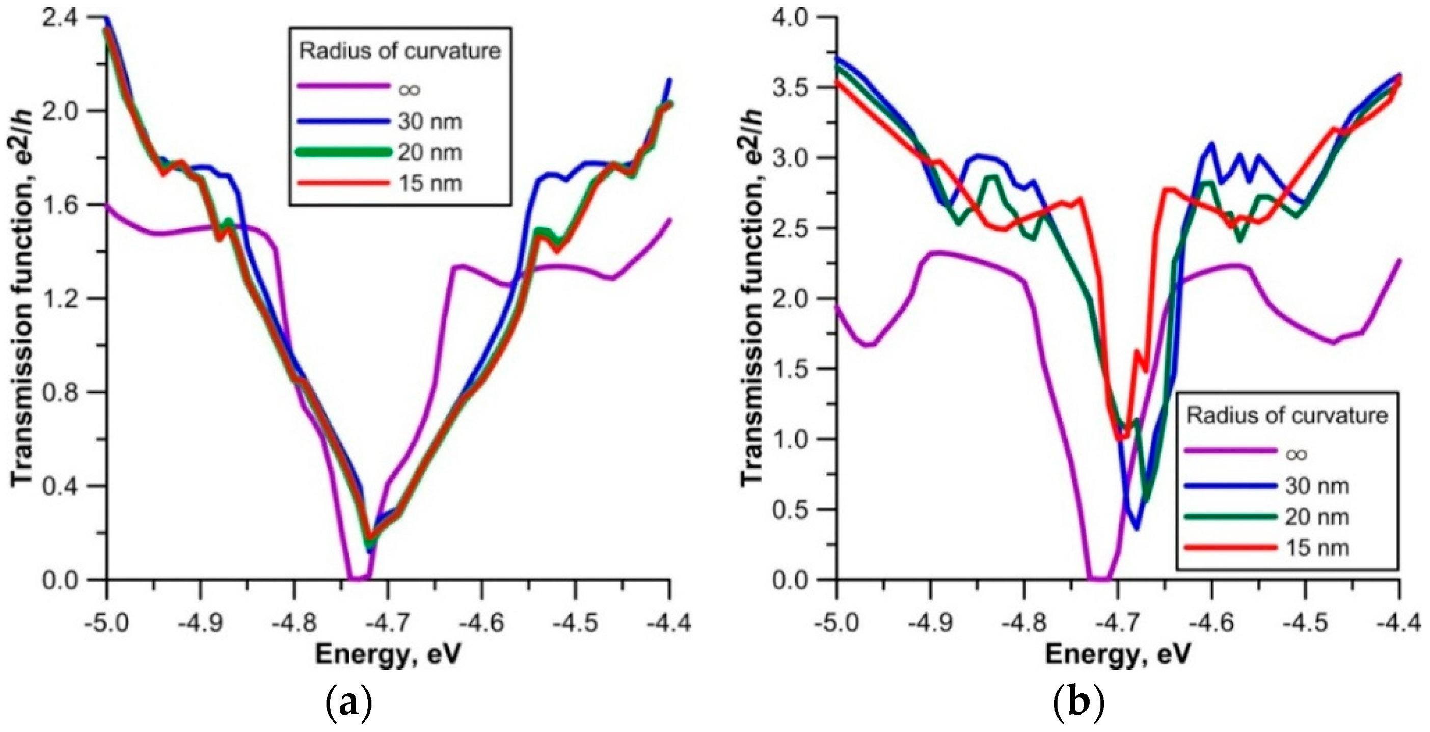
At first, the behavior of the transmission function
T(
E) during bending of mono- and bilayer composite films based on semiconductor CNT (10,0) and metal CNT (12,0) with different inter-tube distances was investigated. Initially, the function
T(
E), regardless of the CNT type and the number of layers, exhibited a small gap near the Fermi level (0.2–0.5 eV), i.e., zero conductivity. The presence of the gap was due to the peculiarity of the conductivity of zigzag CNTs. As is known, zigzag CNTs, even metal, are characterized by the presence of a small area of zero conductivity near the Fermi level. However, during bending, accompanied by re-hybridization and additional overlapping of electron clouds, the zero-conductivity gap completely disappears for all types of composite films, regardless of the CNT type and the number of layers. As expected, the electrical conductivity of composite films reacted differently to bending. The nature of the response was determined only by the type of conductivity of CNTs. For samples based on metallic CNTs, the conductivity at the Fermi level increased with increasing curvature (decreasing radius of curvature), regardless of the layering. At a radius of curvature of ~15 nm, the composite films based on CNT (12,0) already had one conduction channel at the Fermi level. For clarity,
Figure 7 shows the plots of changes in
T(
E) of monolayer films as the radius of curvature decreased, i.e., as the bending angle increased. The plots are given for CNTs (10,0) and (12,0) with the same inter-tube distance of 10 hexagons. The unit of measurement for
T(
E) is the conductance quantum. A violet color represents a plot corresponding to the infinite radius of curvature, when bending is absent. The behavior of
T(
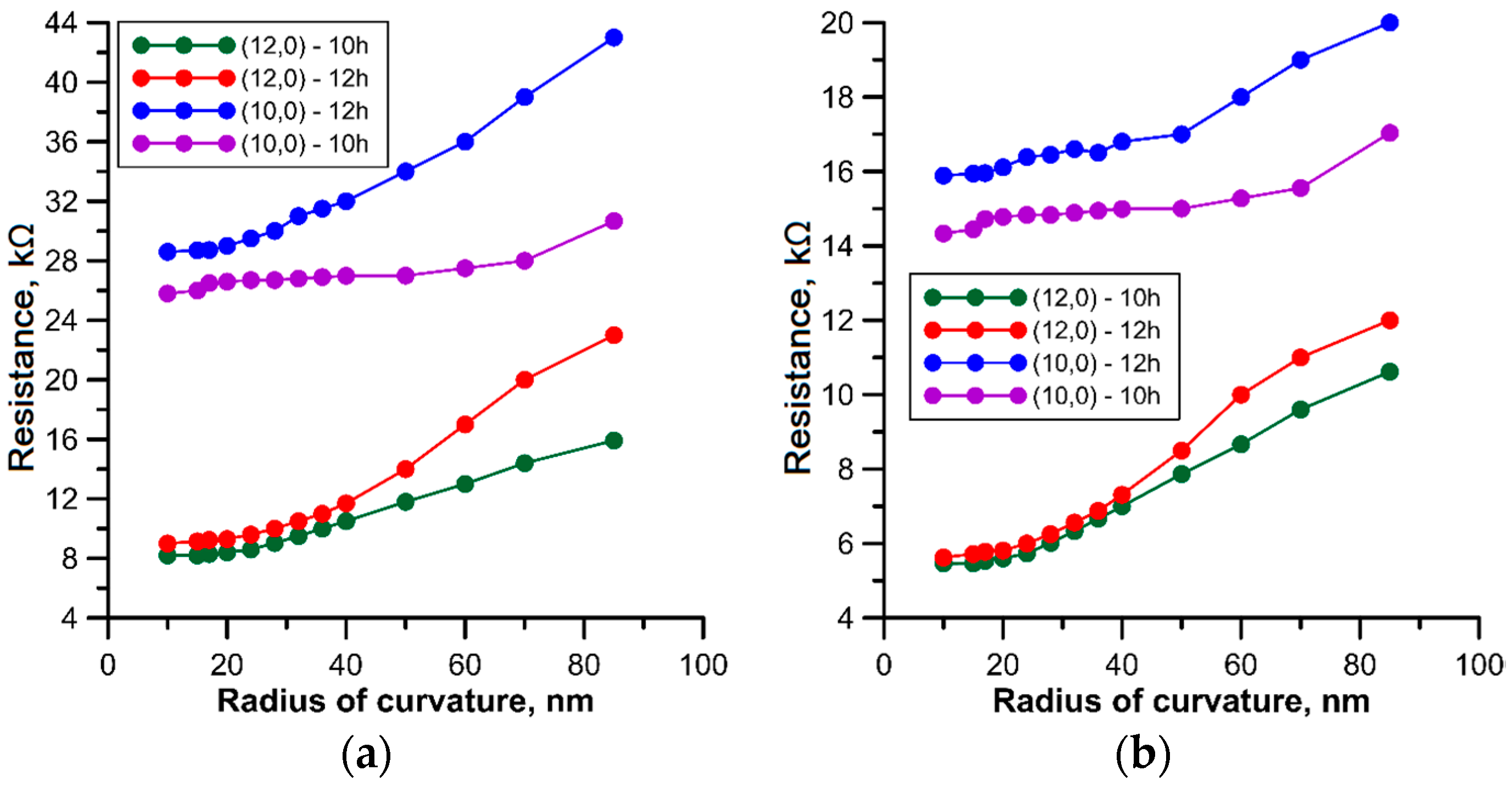
E) with increasing bending qualitatively predicts an increase in conductivity. The value of conductivity
G gives a quantitative prediction, and the value of electrical resistance
R(Ω) is calculated using conductivity
G. Plots of the change in electrical resistance
R during bending in the
Y-direction are shown in
Figure 8 for mono- and bilayer composite films with CNTs (12,0) and (10,0) at different inter-tube distances. An analysis of the plots shows that the trend in the changes of electrical resistance was the same for both types of films, i.e., resistance decreased. The lowest value of
R was observed for composite films with metal CNT (12,0). These films initially had a lower electrical resistance than samples with semiconductor CNTs, which was quite expected. However, it should be noted that the electrical resistance of an individual CNT (10,0) was significantly greater than the resistance of a composite film with the same CNT. This was due to the covalent bonding of CNT with graphene. It can also be seen from the plots that the resistance of the two-layer film was 1.5–2 times less than that of the monolayer film. This can be explained by the presence of two channel-tubes in a super-cell, i.e., two conductors instead of one.


