Article

Torsional Fretting Wear Behavior of PVD TiCN Coated CuNiAl Blade Bearing in Oil and Artificial Seawater

1
The State Key Laboratory of Digital Manufacturing Equipment and Technology, School of Mechanical Science and Engineering, Huazhong University of Science and Technology, Wuhan 430074, China
2
HUST-SHENZHEN Research Institute, No 9, Avenue 3, Yuexing, Yuehai Street, Nanshan District, Shenzhen 518507, China
*
Author to whom correspondence should be addressed.
Coatings 2019, 9(2), 140; https://doi.org/10.3390/coatings9020140
Submission received: 23 January 2019 / Revised: 11 February 2019 / Accepted: 19 February 2019 / Published: 20 February 2019

Abstract

:
The feasibility of alleviating torsional fretting wear of the blade bearing by preparing PVD TiCN coating was studied. The results show that the friction torque was highly influenced by the wear debris acting as the solid lubricant. The TiCN coating reduced the wear volume by 97.6% and 62.3% in oil and artificial seawater, respectively, which was mainly due to an increase in surface hardness. In oil, the produced sulfates and phosphates prevent seizures between the friction pair and the worn surface was characterized by polishing wear. In artificial seawater, the wear mechanism was a combination of mechanical wear and corrosion wear. This study reveals that the TiCN coating is suitable for alleviation of fretting wear in the blade bearing.

1. Introduction

Fretting is the micro-scale relative sliding between contact interfaces due to external vibration [1,2]. This happens in many components, such as the bolt connection, blade/disk interface and steel wire in hoisting ropes [3,4]. Reducing fretting damage can help to prolong the service life of mechanical components [5].
Due to its complexity, the measures for alleviation of fretting wear are varied and sometimes contradictory. Fu et al. [6] summarized three commonly used methods, including design optimization, use of lubricants and adoption of surface engineering. In recent years, the development of methods based on PVD technology allows for the preparation of coatings with excellent wear resistance [7]. Many researchers studied the effect of PVD coating by comparing this with the uncoated matrix material. Wu et al. [8] comparatively investigated the fretting performance of PVD TiN coating and high-speed steel under different relative humidity and normal loads. Sung et al. [9] compared the wear volumes and wear mechanisms of TiN coated and uncoated zircaloy-4 tubes with a cylinder-to-cylinder contact test rig. Larbi et al. [10] investigated the fretting damage of multilayer PVD TiAlCN/TiAlCN/TiAl coating and uncoated AISI 4140 steel. Wu et al. [11] studied the fretting behavior of PVD TiN coated steel by comparing this with the uncoated steel in different aqueous solutions, including distilled water, seawater and sodium phosphate solutions. All the above-mentioned studies found that the PVD coatings showed excellent fretting wear resistance.
However, almost all the experimental tests were conducted under the tangential mode with point contact. However, in real applications, many fretting failures happen under other fretting modes and contact forms. For example, in the railway system, rotational fretting occurs in the locomotive wheel-set fitting surfaces with concave-on-concave contact. Besides, many ball and socket joints experience dual rotary fretting (combined with the rotational and torsional fretting) with curve-on-curve contact [12]. The pressure distribution, third body and lubricating behavior vary with a change in fretting modes and contact forms [13], leading to the differences in fretting running behaviors and wear mechanisms. Thus, it is meaningful to study PVD coating under other fretting modes and contact forms.
As shown in Figure 1, in a CPP, the blade bearing is composed of a blade foot, blade carrier and the hub. According to a previous study [14], when the propeller rotates and the pitch is fixed, fretting occurs at the inner radial part of the blade bearing due to a change in sea state. The fretting should be classified as torsional fretting with flat contact [15]. The most commonly used materials for the hub and the blade carrier are CuNiAl and 42CrMo4, respectively. The wear of the hub part is more serious due to the lower hardness of CuNiAl. The hub is processed in an integrated way so a comprehensive property should be considered in the selection of material. Although some materials can have more excellent anti-wear properties, they may have low corrosion resistance or strength. The CuNiAl has an excellent comprehensive property and cannot be easily replaced by other materials. When the material is unchanged, preparing the coating is a good way to improve the wear resistance. Preparing the soft PTFE(Teflon) coating has been proven to be infeasible by Godjevac et al. [14] and they subsequently recommended hard coatings. Among the PVD coatings, the TiCN coating has been increasingly studied [16], which has the common features and excellent performance of TiN and TiC [17,18]. It can bond well on the substrate [19] and exhibit excellent corrosion [20] and wear [21] resistance. However, almost all the existing TiCN coating studies focus on the sliding wear properties and the investigations on the fretting properties are limited.
In this study, the feasibility of alleviating torsional fretting wear of the blade bearing by preparing a PVD TiCN coating was investigated. This was compared with the uncoated CuNiAl. The influence of normal loads and lubricating mediums, including oil and artificial seawater, were discussed. This study can not only deepen our understanding of the PVD TiCN coating, but also provide guidance for alleviation of fretting wear in the blade bearing.

2. Experimental Method and Materials

2.1. Specimens

As in our previous studies [22,23], the 42CrMo4 and CuNiAl were chosen for the upper and lower specimens, respectively. The contact between the blade carrier and the hub is a full ring contact at the inner radial part (Figure 1) and the fretting can be simulated by applying a normal load over the small-amplitude reciprocating rotation friction pair (Figure 2a). In the specimen design, the lower specimens were machined to have dimensions of 15 mm × 50 mm. The upper specimens were designed by cutting a raised ring with just two 45° sectors left (Figure 2b) so the contact between the upper and lower specimens was a partial ring. Reducing the contact area can help to increase the contact pressure. Under the same normal load and during the same test duration, the wear depth can be increased, which improves the measurement accuracy of wear volume [24].
The TiCN coating was prepared on the lower specimens with reactive ion plating by Baotai Coating Technology Co., Ltd (Dongguan, China). The preparing parameters were chosen based on the physical and mechanical properties and the experience of the engineers. Before the coating deposition, the CuNiAl substrate surfaces were polished to Sa = 0.05 μm (arithmetic mean deviation of the surface) and the ions were cleaned in argon for 15 min. During the deposition, an electron beam was used to evaporate titanium and produce titanium vapor. Besides, acetylene and nitrogen were added to produce the TiCN coating. The deposition was done with a substrate bias of −200 V. The temperature and deposition rate were set at 500 °C and 3 μm/h, respectively.

2.2. Fretting Tests

The fretting test rig was self-made and was illustrated in reference [25]. The upper specimen was stationary and connected with a dynamic friction torque sensor. The lower specimen was driven by a step motor and moved relatively with the upper specimen. In Figure 3, only the core components of the specimens and the lubrication tank are presented.
The experimental parameters were set based on the actual working conditions of the blade bearing. During service, the blade bearing interface is lubricated by the hydraulic oil but the seawater can intrude into the hub and cause the deterioration of the lubrication. Thus, the fretting tests were conducted under oil (ISO VG 46) and artificial seawater (prepared based on standard ASTM 1141–98) lubrications. The temperature was the ambient temperature of 25 °C and the relative humidity was 50–60%. The real normal pressure of the investigated interface was referred to when setting the experimental normal loads. In this study, the tests were performed under different normal loads of 43 N, 86 N and 106 N. They were chosen based on the effect of rotation speed of the controllable pitch propeller to the contact pressure of the blade bearing interface and the relationship of the normal load with contact area of the specimen [25]. The other test parameters were selected as: frequency of 2 Hz, number of cycles of 60,000 and angular displacement amplitude of 1.5°. Before the tests, the specimens were soaked in alcohol and ultrasonically cleaned for 5 min. The alcohol was absolute ethanol (purity higher than 99.7%), which was purchased from Tianjin Fuchen Chemicals Reagent Factory (Tianjin, China).

2.3. Analysis Methods

Surface morphology of the TiCN coating was examined by an OLYMPUS optical-digital DSX 510 microscope (Tokyo, Japan). The phase analysis of the deposited coating was conducted by means of X-ray diffractometer (BRUCKER, D8 ADVANCE (karlsruhe, Germany)) using the grazing angle mode and the incident beam angle was set at 3° [26]. The nanohardness measurement was carried out with a nanoindenter (Anton Parr NHT2), using a triangular diamond Berkovich pyramid [27].
During the fretting process, the variation of friction torques with time was recorded. After the fretting tests, the debris on the worn surface was ultrasonically cleaned in the alcohol before the optical morphology and 3D profile of the worn surface were obtained with the optical digital microscope [28,29]. The wear volume was acquired by analyzing the 3D profile using a OLYMPUS Stream contained in the microscope. A scanning electron microscope (SEM, Quanta 3D FED (Göttingen, Germany)) with energy dispersive spectroscope (EDX) was used for high magnification observation and chemical element analysis [30]. An X-ray photoelectron spectroscope (XPS, VG Multilab 2000 (Waltham, Massachusetts, America)) was used to explore the composition in the worn area.

3. Results and Discussion
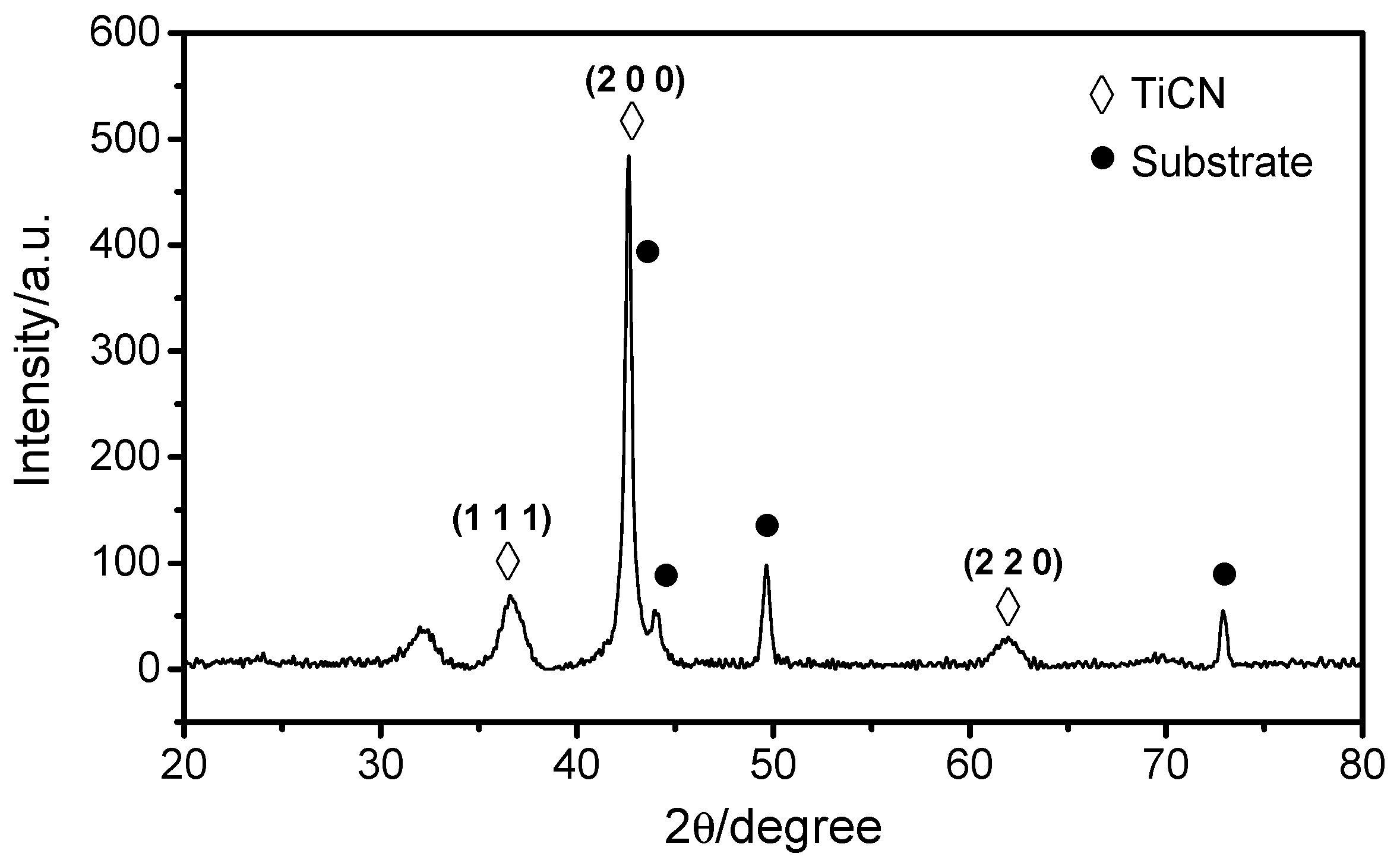
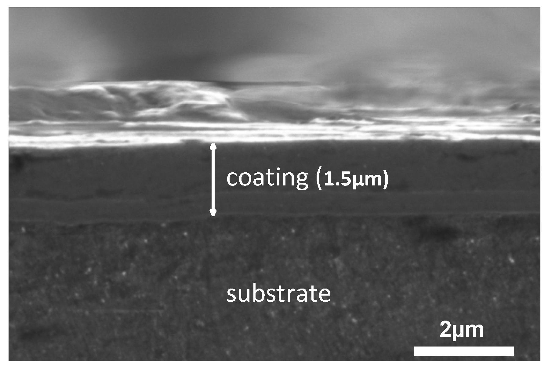
3.1. Microstructure

An X-ray diffractometer (XRD, XRD-7000S (Kyoto, Japan)) was used for the phase analysis of the coating, as shown in Figure 4. It can be seen that the phase is a combination of TiCN and the matrix [31]. The preferred orientation of TiCN is the (200) crystal plane.
Figure 5 shows the SEM surface morphology of the prepared TiCN coating. There are stripes, particles and cavities that are distributed unevenly on the coating surface. The stripes should have resulted from the original stripes on the substrate surface. The particles present different shapes and sizes. The cavities generally have a round shape. According to literature [32], the formation of these particles and cavities is related to the preparation process of reactive ion plating. These particles and cavities lead to an increase in the coating surface roughness and the analysis with an optical microscope (Olympus, DSX510 (Kyoto, Japan)) shows that the roughness Sa was 0.847 μm.
SEM was used to observe the bonding between the CuNiAl substrate and the TiCN coating in addition to the cross-sectional microstructure of the coating (Figure 6). It shows that the TiCN coating has a dense structure and no internal cracks and voids can be observed. The coating is well bonded to the substrate as there are no cracks or voids in the bonding sites. The thickness of the coating is approximately 1.5 μm.
Nanoindentation tests were performed with the continuous stiffness measurement (CSM) mode using a nanoindentation instrument (Anton Parr NHT2 (Glaz, Austria)) equipped with a Berkovich indenter. A total of 10 imprints were made on each specimen for the Nano-hardness measurements. The nanohardness and elastic modulus were calculated and analyzed based on the curves obtained using the Oliver and Pharr method with a maximum load of 10 mN, loading and unloading rates of 20 mN/min and a dwell time of 10 s. Three different areas were selected on each sample for measurements to ensure data reliability.
Figure 7 shows the loading–unloading curves for the CuNiAl and TiCN coating. The hardness and elastic modulus for the CuNiAl are about 4.277 ± 0.6 GPa (mean ± standard deviation) and 193 ± 13.6 GPa, respectively and these values for the TiCN coating are 25.069 ± 1.6 GPa and 270 ± 18.5 GPa, respectively. It can be seen that the surface hardness is significantly increased after preparing the TiCN coating. According to Archard’s theory, the surface hardness is negatively related to the wear rate [33].

3.2. Friction Behavior

Friction torque curves of CuNiAl and TiCN coating fretting against 42CrMo4 under different test conditions are shown in Figure 8. All the friction torque curves show similar characteristics. The first part is the running-in phase with the friction torque rises rapidly while the second part represents a decrease in the friction torque before running into the stable stage. The reason for this decrease is the interface becoming smoother after the running in process. Besides, the generated wear debris combined with the lubricating medium formed a hydrated surface layer, which decreases the friction as a result of the low shear strength [34].
The stable friction torque was calculated by averaging the friction torque of the last 30000 cycles:
T s t a b = 1 30000 [ 30000 60000 T i ] ,
where T i refers to the friction torque of the number i cycle.
As can be seen from Figure 9a, in oil, the friction torque of CuNiAl is higher than that of TiCN coating at 43 N and 86 N, while the opposite occurs at 106 N. There suggests that the friction torque was affected by both the initial surface conditions and the generated wear debris [35,36,37]. In oil and at low normal loads, little debris was produced so the initial surface condition played a more important role. The TiCN coating surface was distributed with a large number of particles and pits. This reduces the friction torque by decreasing the actual contact area [38] so the friction torque was lower for the TiCN coating. At 106 N, the wear for both CuNiAl and TiCN coating was aggravated. In this case, the friction torque was influenced more by the wear debris. The wear rate was higher for the CuNiAl than for the TiCN coating (to be discussed in the next section) as the CuNiAl produced more wear debris. According to a previous study [39], it is difficult to reject the generated wear debris from the fretting interface and it works as a solid lubrication to reduce the friction so the friction torque was lower for the CuNiAl.
In artificial seawater, the stable friction torque is always lower for the CuNiAl than for the TiCN coating (Figure 9b). This is because the artificial seawater was highly corrosive so the wear rate for both CuNiAl and TiCN coatings are higher than that in oil [32,40]. In this case, the friction torque was also more affected by the wear debris than by the initial surface condition. The CuNiAl produced more wear debris due to the higher wear rate so the friction torque was lower for the CuNiAl due to the solid lubrication effect of the wear debris.
For the controllable pitch propeller, the influence of friction torque has two sides [14]. Reducing the friction torque ultimately reduces the energy consumption during pitch adjustment but also promotes the occurrence of fretting or an increase in the fretting amplitude. In the real application, the lubrication of the blade bearing is achieved by the oil in the hub [14].Thus, when evaluating the influence of TiCN coating on the friction torque, the data in Figure 9a should be referred to. It indicates that at low normal loads (corresponding to low rotation speeds of the propeller), the TiCN coating presents lower friction torque, indicating that the energy consumption during pitch adjustment will be reduced. The opposite will occur at high normal loads but it also permits us to avoid the occurrence of fretting or reduces the fretting amplitude.
In fact, for the blade bearing, the service life is mainly decided by the wear rate rather than the friction torque [14] as the friction has the greatest impact on the energy consumption and fretting amplitude. However, the wear leads to an increase in the assembling clearance and a decrease in the dynamic sealing property. Excessive wear rate can lead to the final failure of the blade bearing. Thus, more attention should be paid to the wear property.

3.3. Wear Behavior

The 2D profiles of the worn surfaces in oil and artificial seawater are shown in Figure 10. In oil, the wear scars of CuNiAl and TiCN coatings are narrow and shallow (Figure 10a). Specifically, the wear scar width and depth of CuNiAl are about 500 μm and 1.2 μm, respectively. The wear of TiCN coating is so slight that it can hardly be identified from the 2D profile. Figure 10b shows that in artificial seawater, the wear scars of CuNiAl and TiCN coatings have about the same width but the TiCN coating presents a maximum depth of just 1 μm (CuNiAl, about 3 μm).
In fretting tests, the wear volume and the accumulated dissipated energy are related as wear results from the work of the tangential force between the interfaces [8]. The wear volume was measured by the means of the optical digital microscope (OLYMPUS, DSX 510 (Tokyo, Japan))/ The accumulated dissipated energy was acquired by integrating the fretting loops for all the 60,000 cycles. Figure 11 and Figure 12 display the variation of wear volume with accumulated dissipated energy obtained after 60,000 cycles. It can be seen that a linear relation exists for both the CuNiAl and the TiCN coating. The slope is the energetic wear coefficient and reflects the wear resistance. For the uncoated and TiCN coated CuNiAl, the energetic wear coefficients in oil are 14,247 μm3/J and 341 μm3/J, respectively (Figure 11). In artificial seawater, they are 8541 μm3/J and 3232 μm3/J, respectively (Figure 12). Thus, after preparing the coating, the wear rate decreased by about 97.6% and 62.3% in oil and in artificial seawater, respectively. The main reasons behind this includes the generation of compression residual stress, reduction of friction force and increase in surface hardness [41]. In this study, the residual stress is not evaluated and there is even an increase in the friction torque so the reduction of the wear rate is possibly mainly due to an increase in the surface hardness.
Figure 11 and Figure 12 indicate that the TiCN coating reduces the wear rate significantly, especially in oil. The blade bearing works in oil so it can be inferred that if the TiCN coating is prepared and added to the blade bearing, the service life will be significantly prolonged.

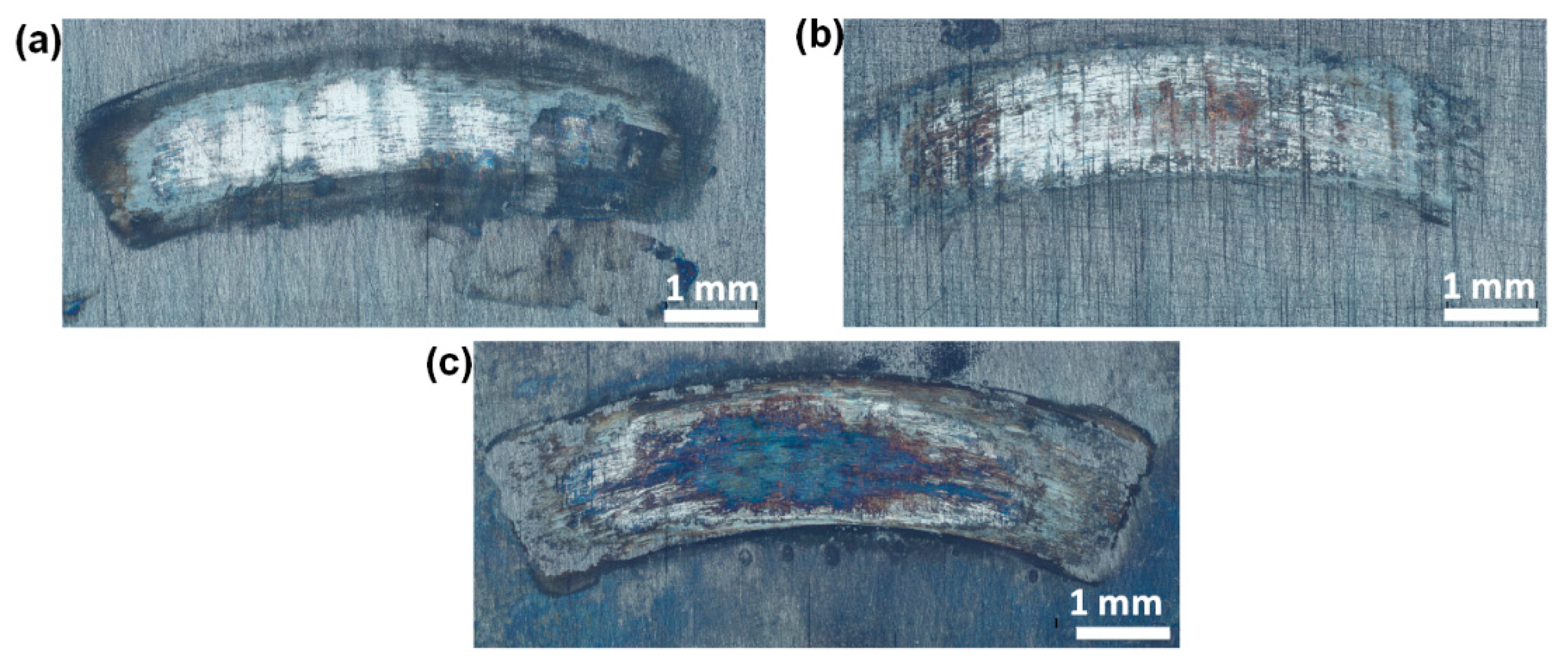
3.4. Wear Scar Observation

In order to get an intuitive understanding of the wear degree, the wear scar was firstly observed under the optical digital microscope.
In previous studies, we have studied the optical features of CuNiAl in oil and artificial seawater [40]. As shown in Figure 13, in oil, the wear occurs mainly at the inner area of the friction interface with the wear scar that has a width of approximately 700 μm, which is much smaller than the contact width of the friction pair (2 mm). This is mainly because under flat contact, the penetration of the lubricating oil into the inner area becomes more difficult so the inner area suffered more serious wear due to poorer lubrication. The main features of the wear scar are the scratches along the relative sliding direction (Figure 13a). In artificial seawater, the wear scar was obviously aggravated compared to that in oil. In addition, the wear surface was corroded in the seawater as evidenced by the corrosion flaking pits (Figure 13b). The distribution of corrosion products can not only separate the contact area of upper and lower specimen, but also show a lubricating effect by acting as solid lubricants [42].
The wear scars of the TiCN coating in oil are shown in Figure 14. The wear of the coating surface is very slight at 43 N and 86 N (Figure 14a) with only some parallel abrasive wear marks able to be observed. These wear marks are considered to be caused by the particles falling off the surfaces, which subsequently causes a scratching effect on the surface that is embedded in the surface during the sliding process. The wear obviously increases at 106 N (Figure 14b) but the wear scar area of the TiCN coating is still much smaller than that of CuNiAl, indicating that the TiCN coating has a significantly better anti-wear property than the CuNiAl. The optical morphology of the TiCN coating worn surface in artificial seawater is shown in Figure 15, which demonstrates that both the worn surface area and the wear scar width are much larger than that in oil. Thus, there is a significant increase in the wear degree compared to that in oil.
The worn surfaces were further observed under the SEM for wear mechanism analysis. Figure 16 presents the SEM micrographs of the TiCN coating in oil. According to the previous study [16], the wear mechanisms in the presence of an oil lubricant that are responsible for causing damage to the coating layer can be classified into two groups of polishing and abrasion. In the inner area, the worn surface seems smoother than the unworn surface, indicating that the polishing wear dominated. At the edge part, delamination occurred. Furthermore, a considerable number of deep, abrasive marks can be observed along the fretting direction due to the abrasive action. It is generally believed that these marks are produced by the action of tiny fracture coating particles that are entrapped in the fretting area and act as indentures [16].
Figure 17 presents SEM micrographs of the TiCN coating in the seawater. It can be seen that there is a serious worn area that is about 300 μm wide. Many cracks are generated and some of the coatings have peeled off the surface due to delamination. With the strain hardening of worn surface, delamination occurs during the fretting process due to the nucleation and expansion of subsurface cracks. Besides, the Cl ions in the seawater can be destructive on the passivation layer and the coating surface [32]. During wear, the coating was activated and anodic dissolution happened in the electrolyte, resulting in corrosion damage. Thus, the wear mechanism was a coexistence of mechanical wear and tribochemical wear.
From the wear scar observation, it can be seen that after 60,000 fretting cycles, the wear of the TiCN coating is very slight in oil but slightly serious in artificial seawater. Thus, it is more suitable to use the coating in oil than in seawater. As the blade bearing works in oil in the real application, it can be seen that the TiCN coating is suitable to be used for the fretting wear alleviation of the blade bearing.

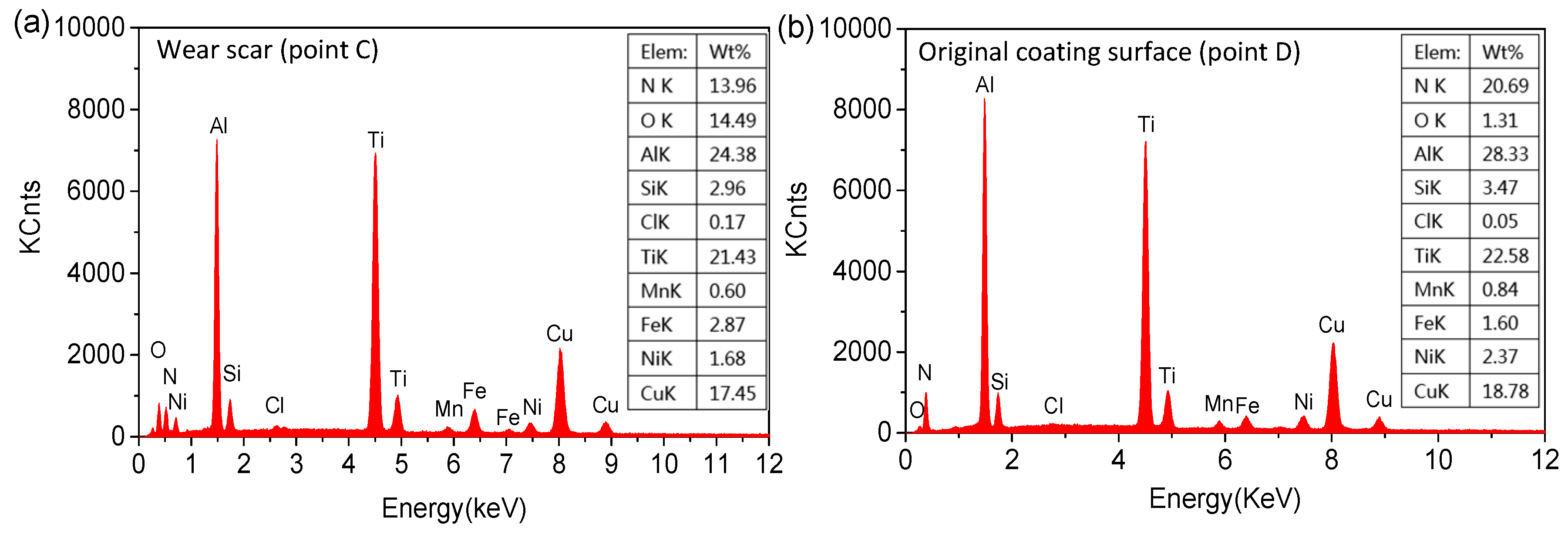
3.5. Tribochemical Behaviors

Figure 18 shows the EDX patterns of the TiCN coating (Figure 16, Point A and B) in oil. It indicates that compared with the unworn zone, the Fe content increased from 0.82% to 45.89% in the worn zone while the Cr content increased from 0.06% to 0.41%, indicating that material transfer occurred from the upper specimen to the lower specimen. The S element was 1.97% on the worn surface but not detected on the original coating surface, which indicates the absorption of S on the worn surface from the lubricant.
Figure 19 shows the EDX patterns of the TiCN coating (Figure 17, Point C and D) in artificial seawater. Compared with that in the unworn zone, the O content increased from 1.31% to 14.49% in the worn zone, indicating that oxidation reaction occurred during the fretting. The Fe element content increased from 1.60% to 2.87% while the Cl element content increased from 0.05% to 0.17%, which indicated that material transfer occurred from the upper specimen and artificial seawater to the coating surface.
Besides, during the fretting process, a chemical reaction can occur between the lubricant and the friction surface, which forms complex compounds. XPS analysis was conducted to provide some insight into this after the worn specimens were ultrasonically cleaned in the alcohol to remove the contaminants. The XPS spectra of some key elements in the worn area are given in Figure 20. As shown in Figure 20a, in oil, CuO and Cu(OH)2 may be formed from copper due to the binding energy of Cu 2p at 934.4 eV. In artificial seawater, the peak of Cu 2p around 932.3 eV should be inferred as Cu, Cu2O, Cu2S or CuCl [43]. The Al 2p spectra in Figure 20b indicates that metallic Al (Al 2p3/2 at 72.8 eV and Al 2p1/2 at 73.2 eV), Al2O3 (76.1 eV) and/or Al(OH)3 (76.0 eV) may exist although there may also be other compounds formed due to the broad features [44,45]. From Figure 20c, oxides, such as MnO2, Mn2O3, MnO and Mn3O4, may be formed from manganese, which can be identified by the Mn 2p peak at 650 eV. However, this could also exist in other forms, such as MnFe2O4 and MnCr2O4 [40]. In Figure 20d, in oil, Fe 2p peaked at 720.2 eV, which is ascribed to Fe. In artificial seawater, the peak at 713.3 eV and 713.6 eV are assigned to Fe2(SO4)3 and FeSO4 respectively, indicating that sulfates were formed on the wear scars [23,44,46]. Besides, in oil, the S 2p peaks at 161.9 eV shows the presence of S2− (Figure 20e), which is attributed to sulfides, such as CuS, ZnS, TiS2 and MoS2 [47]. Furthermore, phosphates, such as AlPO4, can be formed (Figure 20f, P 2p, 133.3eV). According to a previous study [44], these sulfates and phosphates can prevent adhesion between the friction pair and reduce the friction and wear. In artificial seawater, the Cl 2p peaked at 200.4 eV (Figure 20g), indicating the existence of Cl [48,49]. This should be assigned to CuCl2, FeCl2, ZnCl2, etc. On one hand, the chlorides have a lubricating effect [42], but on the other hand, they are highly conductive and can promote the dissolution of metals due to the electrochemical reactions [50].

4. Conclusions

With comparison to the uncoated CuNiAl, the fretting wear of PVD TiCN coating was studied experimentally under different test conditions. The main conclusions obtained are as follows:
  • The friction torque of CuNiAl was lower than that of TiCN coating in artificial seawater. This was because the CuNiAl produced more wear debris, which played the role of a solid lubricant to reduce the friction.
  • Compared with CuNiAl, the TiCN coating reduced the wear volume by 97.6% and 62.3% in oil and artificial seawater, respectively, which was mainly attributed to an increase in surface hardness.
  • In oil, the sulfates and phosphates can prevent adhesion between the friction pair and reduce the friction and wear. The worn surface was characterized by polishing wear. In artificial seawater, the wear mechanism was a combination of cracks, delamination and corrosion wear.
  • Through comprehensive research on the friction and wear properties, the PVD TiCN coating was determined to more suitable for the alleviation of fretting wear, which happens under the oil lubrication (such as the blade bearing).

Author Contributions

Conceptualization, P.Z. and J.W.; Formal analysis, P.Z.; Investigation, J.W.; Methodology, P.Z.; Supervision, J.W.; Validation, P.Z.; Writing – original draft, P.Z.; Writing – review & editing, J.W.

Funding

This work was funded by National Basic Program of China (973 Program, Grant No 2014CB046075), National Natural Science Foundation of China (Grant No. 51705178, 51575235) and Shenzhen Basic Scientific Research Project (JCYJ2017030717134710).

Conflicts of Interest

Declare conflicts of interest or state “The authors declare no conflict of interest.”

References

  1. Zhang, H.Y.; Blunt, L.A.; Jiang, X.Q.; Fleming, L.T.; Barrans, S.M. The influence of bone cement type on production of fretting wear on the femoral stem surface: A preliminary study. Clin. Biomech. 2012, 27, 666–672. [Google Scholar] [CrossRef] [PubMed]
  2. Zhai, W.Z.; Lu, W.L.; Zhang, P.; Wang, J.; Liu, X.J.; Zhou, L.P. Wear-triggered self-healing behavior on the surface of nanocrystalline nickel aluminum bronze/Ti 3 SiC 2 composites. Appl. Surf. Sci. 2018, 436, 1038–1049. [Google Scholar] [CrossRef]
  3. Gallego, L.; Fulleringer, B.; Deyber, S.; Nelias, D. Multiscale computation of fretting wear at the blade/disk interface. Tribol. Int. 2010, 43, 708–718. [Google Scholar] [CrossRef]
  4. Zhai, W.Z.; Lu, W.L.; Chen, Y.M.; Liu, X.J.; Zhou, L.P.; Lin, D. Gas-atomized copper-based particles encapsulated in graphene oxide for high wear-resistant composites. Compos. Part. B-Eng. 2019, 157, 131–139. [Google Scholar] [CrossRef]
  5. Zhai, W.Z.; Lu, W.L.; Liu, X.J.; Zhou, L.P. Nanodiamond as an effective additive in oil to dramatically reduce friction and wear for fretting steel/copper interfaces. Tribol. Int. 2019, 129, 75–81. [Google Scholar] [CrossRef]
  6. Fu, Y.Q.; Wei, J.; Batchelor, A.W. Some considerations on the mitigation of fretting damage by the application of surface-modification technologies. J. Mater. Process. Tech. 2000, 99, 231–245. [Google Scholar] [CrossRef]
  7. Polcar, T.; Novák, R.; Široký, P. The tribological characteristics of TiCN coating at elevated temperatures. Wear 2006, 260, 40–49. [Google Scholar] [CrossRef]
  8. Wu, P.Q.; Chen, H.; Van Stappen, M.; Stals, L.; Celis, J.P. Comparison of fretting wear of uncoated and PVD TiN coated high-speed steel under different testing conditions. Surf. Coat. Tech. 2000, 127, 114–119. [Google Scholar] [CrossRef]
  9. Sung, J.H.; Kim, T.H.; Kim, S.S. Fretting damage of TiN coated zircaloy-4 tube. Wear 2001, 250, 658–664. [Google Scholar] [CrossRef]
  10. Larbi, A.B.C.; Tlili, B. Fretting wear of multilayered PVD TiAlCN/TiAlN/TiAl on AISI 4140 steel. Surf. Coat. Tech. 2006, 201, 1511–1518. [Google Scholar] [CrossRef]
  11. Wu, P.Q.; Mohrbacher, H.; Celis, J.P. The fretting behaviour of PVD TiN coatings in aqueous solutions. Wear 1996, 201, 171–177. [Google Scholar] [CrossRef]
  12. Zheng, J.F.; Yang, S.; Shen, M.X.; Mo, J.L.; Zhu, M.H. Study on rotational fretting wear under a ball-on concave contact configuration. Wear 2011, 271, 1552–1562. [Google Scholar] [CrossRef]
  13. Zhang, P.; Lu, W.; Liu, X.; Zhai, W.; Zeng, W. Torsional fretting and torsional sliding wear behaviors of CuNiAl against 42CrMo4 under dry condition. Tribol. Int. 2018, 118, 11–19. [Google Scholar] [CrossRef]
  14. Godjevac, M. Wear and Friction in a Controllable Pitch Propeller. Doctoral Dissertation, TU Delft, Delft University of Technology, 2010. [Google Scholar]
  15. Godjevac, M.; Van Beek, T.; Grimmelius, H.T.; Tinga, T.; Stapersma, D. Prediction of fretting motion in a controllable pitch propeller during service. Proc. Inst. Mech. Eng. Part M J. Eng. Marit. Environ. 2009, 223, 541–560. [Google Scholar] [CrossRef]
  16. Su, Y.L.; Yao, S.H.; Leu, Z.L.; Wei, C.S.; Wu, C.T. Comparison of tribological behavior of three films—TiN, TiCN and CrN—grown by physical vapor deposition. Wear 1997, 213, 165–174. [Google Scholar] [CrossRef]
  17. Karlsson, L.; Hultman, L.; Sundgren, J.E. Influence of residual stresses on the mechanical properties of TiCxN1–x (x= 0, 0.15, 0.45) thin films deposited by arc evaporation. Thin. Solid. Films. 2000, 371, 167–177. [Google Scholar] [CrossRef]
  18. Wei, C.; Lin, J.F.; Jiang, T.H.; Ai, C.F. Tribological characteristics of titanium nitride and titanium carbonitride multilayer films: Part II. The effect of coating sequence on tribological properties. Thin. Solid. Films. 2001, 381, 104–118. [Google Scholar] [CrossRef]
  19. Guu, Y.Y.; Lin, J.F.; Ai, C.F. The tribological characteristics of titanium nitride, titanium carbonitride and titanium carbide coatings. Thin. Solid. Films. 1997, 302, 193–200. [Google Scholar] [CrossRef]
  20. Surviliene, S.; Bellozor, S.; Kurtinaitiene, M.; Safonov, V.A. Protective properties of the chromium–titanium carbonitride composite coatings. Surf. Coat. Tech. 2004, 176, 193–201. [Google Scholar] [CrossRef]
  21. Vancoille, E.; Celis, J.P.; Roos, J.R. Dry sliding wear of TiN based ternary PVD coatings. Wear 1993, 165, 41–49. [Google Scholar] [CrossRef]
  22. Lu, W.L.; Zhang, P.; Liu, X.J.; Zhai, W.Z.; Zhou, M.Z.; Luo, J.; Zeng, W.H.; Jiang, X.Q. Influence of surface topography on torsional fretting wear under flat-on-flat contact. Tribol. Int. 2017, 109, 367–372. [Google Scholar] [CrossRef]
  23. Lu, W.; Zhai, W.; Zhang, P.; Zhou, M.; Liu, X.; Zhou, L. Effect of different levels of free water in oil on the fretting wear of nickel-aluminum bronze based composites. Wear 2017, 390, 376–384. [Google Scholar] [CrossRef]
  24. Zhang, P.; Lu, W.L.; Liu, X.J.; Zhou, M.Z.; Zhai, W.Z.; Zhang, G.P.; Zeng, W.H.; Jiang, X.Q. Torsional fretting wear behavior of CuNiAl against 42CrMo4 under flat on flat contact. Wear 2017, 380, 6–14. [Google Scholar] [CrossRef]
  25. Zhang, P.; Lu, W.L.; Liu, X.J.; Zhai, W.Z.; Zhou, M.Z.; Jiang, X.Q. A comparative study on torsional fretting and torsional sliding wear of CuNiAl under different lubricated conditions. Tribol. Int. 2018, 117, 78–86. [Google Scholar] [CrossRef]
  26. Zhai, W.Z.; Shi, X.L.; Yang, K.; Huang, Y.C.; Zhou, L.P.; Lu, W.L. Tribological Behaviors of Ni 3 Al Intermetallics with MoO 3 Multilayer Ribbon Crystal Prepared by Spark Plasma Sintering. Acta. Metall. Sin. 2016, 30, 576–584. [Google Scholar] [CrossRef]
  27. Lan, P.X.; Meyer, J.L.; Vaezian, B.; Polycarpou, A.A. Advanced polymeric coatings for tilting pad bearings with application in the oil and gas industry. Wear. 2016, 354, 10–20. [Google Scholar] [CrossRef]
  28. Lan, P.X.; Polychronopoulou, K.; Zhang, Y.F.; Polycarpou, A.A. Three-body abrasive wear by (silica) sand of advanced polymeric coatings for tilting pad bearings. Wear 2017, 382, 40–50. [Google Scholar] [CrossRef]
  29. Lan, P.X.; Meyer, J.L.; Economy, J.; Polycarpou, A.A. Unlubricated Tribological Performance of Aromatic Thermosetting Polyester (ATSP) Coatings Under Different Temperature Conditions. Tribol. Lett. 2016, 61, 10. [Google Scholar] [CrossRef]
  30. Zhai, W.Z.; Shi, X.L.; Yang, K.; Huang, Y.C.; Zhou, L.P.; Lu, W.L. Mechanical and tribological behaviors of the tribo-layer with nanocrystalline structure during sliding contact: Experiments and model assessment. Compos. Part. B-Eng. 2017, 108, 354–363. [Google Scholar] [CrossRef]
  31. Wang, Q.Z.; Zhou, F.; Chen, K.M.; Wang, M.L.; Qian, T. Friction and wear properties of TiCN coatings sliding against SiC and steel balls in air and water. Thin. Solid. Films. 2011, 519, 4830–4841. [Google Scholar] [CrossRef]
  32. Shan, L.; Wang, Y.X.; Li, J.L.; Li, H.; Wu, X.D.; Chen, J.M. Tribological behaviours of PVD TiN and TiCN coatings in artificial seawater. Surf. Coat. Tech. 2013, 226, 40–50. [Google Scholar] [CrossRef]
  33. Archard, J.F. Contact and rubbing of flat surfaces. J. Appl. Phys. 1953, 24, 981–988. [Google Scholar] [CrossRef]
  34. Neville, A.; Morina, A.; Haque, T.; Voong, M. Compatibility between tribological surfaces and lubricant additives—how friction and wear reduction can be controlled by surface/lube synergies. Tribol. Int. 2007, 40, 1680–1695. [Google Scholar] [CrossRef]
  35. Kubiak, K.J.; Bigerelle, M.; Mathia, T.G.; Dubois, A.; Dubar, L. Dynamic evolution of interface roughness during friction and wear processes. Scanning 2014, 36, 30–38. [Google Scholar] [CrossRef] [PubMed]
  36. Shi, W.J.; Luo, X.H.; Zhang, Z.T.; Liu, Y.S.; Lu, W.L. Influence of external load on the frictional characteristics of rotary model using a molecular dynamics approach. Comp. Mater. Sci. 2016, 122, 201–209. [Google Scholar] [CrossRef]
  37. Lu, W.L.; Zhang, G.P.; Liu, X.J.; Zhou, L.P.; Chen, L.Z.; Jiang, X.Q. Prediction of Surface Topography at the End of Sliding Running-In Wear Based on Areal Surface Parameters. Tribol. T. 2014, 57, 553–560. [Google Scholar] [CrossRef]
  38. Kubiak, K.J.; Mathia, T.G.; Fouvry, S. Interface roughness effect on friction map under fretting contact conditions. Tribol. Int. 2010, 43, 1500–1507. [Google Scholar] [CrossRef] [Green Version]
  39. Wang, J.; Luo, X.; Sun, Y. Torsional Fretting Wear Properties of Thermal Oxidation-Treated Ti3SiC2 Coatings. Coatings 2018, 8, 324. [Google Scholar] [CrossRef]
  40. Zhang, P.; Liu, X.J.; Lu, W.L.; Zhai, W.Z.; Zhou, M.Z.; Wang, J. Fretting wear behavior of CuNiAl against 42CrMo4 under different lubrication conditions. Tribol. Int. 2018, 117, 59–67. [Google Scholar] [CrossRef]
  41. Holmberg, K.; Matthews, A.; Ronkainen, H. Coatings tribology—contact mechanisms and surface design. Tribol. Int. 1998, 31, 107–120. [Google Scholar] [CrossRef]
  42. Ding, H.Y.; Dai, Z.D.; Zhou, F.; Zhou, G.H. Sliding friction and wear behavior of TC11 in aqueous condition. Wear 2007, 263, 117–124. [Google Scholar] [CrossRef]
  43. Jia, Z.F.; Chen, T.D.; Wang, J.; Ni, J.J.; Li, H.Y.; Shao, X. Synthesis, characterization and tribological properties of Cu/reduced graphene oxide composites. Tribol. Int. 2015, 88, 17–24. [Google Scholar] [CrossRef]
  44. Liu, X.Q.; Zhou, F.; Liang, Y.M.; Liu, W.M. Tribological performance of phosphonium based ionic liquids for an aluminum-on-steel system and opinions on lubrication mechanism. Wear 2006, 261, 1174–1179. [Google Scholar] [CrossRef]
  45. Piao, H.; McIntyre, N.S. Oxidation studies of Au-Al alloys using x-ray photoelectron spectroscopy (XPS) and x-ray absorption near-edge structure (XANES). Surf. Interface. Anal. 2010, 31, 874–880. [Google Scholar] [CrossRef]
  46. Cho, M.H.; Bahadur, S.; Pogosian, A.K. Friction and wear studies using Taguchi method on polyphenylene sulfide filled with a complex mixture of MoS2, Al2O3 and other compounds. Wear 2005, 258, 1825–1835. [Google Scholar] [CrossRef]
  47. Squarcialupi, M.C.; Bernardini, G.P.; Faso, V.; Atrei, A.; Rovida, G. Characterisation by XPS of the corrosion patina formed on bronze surfaces. J. Cult. Herit. 2002, 3, 199–204. [Google Scholar] [CrossRef]
  48. Cui, G.J.; Bi, Q.L.; Zhu, S.Y.; Yang, J.; Liu, W.M. Tribological properties of bronze–graphite composites under sea water condition. Tribol. Int. 2012, 53, 76–86. [Google Scholar] [CrossRef]
  49. Li, W.S.; Wang, Z.P.; Lu, Y.; Yuan, L.H. Corrosion wear behavior of Al-bronzes in 3.5% NaCl solution. J. Mater. Eng. Perform. 2006, 15, 102–110. [Google Scholar] [CrossRef]
  50. Cui, G.J.; Bi, Q.L.; Yang, J.; Liu, W.M. The bronze–silver self-lubricating composite under sea water condition. Tribol. Int. 2013, 60, 83–92. [Google Scholar] [CrossRef]
Figure 1. Assembly of a controllable pitch propeller (CPP) [14].
Coatings 09 00140 g001
Figure 2. (a) Schematic of motion between the hub and blade carrier; and (b) Upper specimen.
Coatings 09 00140 g002
Figure 3. Schematic of the test rig: 1-Upper specimen; 2-Lubricant; 3-Lower specimen; 4-Screw; and 5-Lubricant tank.
Coatings 09 00140 g003
Figure 4. XRD patterns of the TiCN coating.
Coatings 09 00140 g004
Figure 5. SEM micrographs of TiCN coating surface. (a) Macro morphology; (b) Micro morphology.
Coatings 09 00140 g005
Figure 6. Cross-section topography of the TiCN coating.
Coatings 09 00140 g006
Figure 7. Typical loading–unloading curves of CuNiAl and TiCN coating.
Coatings 09 00140 g007
Figure 8. Friction torque curves: (a) in oil; and (b) in artificial seawater.
Coatings 09 00140 g008
Figure 9. Stable friction torque: (a) in oil; and (b) in artificial seawater.
Coatings 09 00140 g009
Figure 10. 2D profile of the worn surfaces: (a) in oil; and (b) in artificial seawater (P = 106 N).
Coatings 09 00140 g010
Figure 11. Wear volume vs. accumulated dissipated energy in oil.
Coatings 09 00140 g011
Figure 12. Wear volume vs. accumulated dissipated energy in artificial seawater.
Coatings 09 00140 g012
Figure 13. Optical morphologies of CuNiAl wear scars:(a) in oil; and (b) in artificial seawater (P = 106 N).
Coatings 09 00140 g013
Figure 14. Optical morphologies of TiCN coating wear scars in oil: (a) 43 N; (b) 86 N; and (c) 106 N.
Coatings 09 00140 g014
Figure 15. Optical morphologies of TiCN coating wear scars in artificial seawater: (a) 43 N; (b) 86 N; and (c) 106 N.
Coatings 09 00140 g015
Figure 16. SEM micrographs of the TiCN coating worn surfaces in oil (P = 106 N): (a) Macro morphology; (b) Central part; (c) Edge part.
Coatings 09 00140 g016
Figure 17. SEM micrographs of the TiCN coating worn surfaces in artificial seawater (P = 106 N): (a) Macro morphology; (b) Edge part; (c) Central part.
Coatings 09 00140 g017
Figure 18. EDX patterns of the TiCN coating on the wear scar and original surface in oil. (a) Wear scar; (b) Original coating surface.
Coatings 09 00140 g018
Figure 19. EDX patterns of the TiCN coating on the wear scar and original surface in artificial seawater. (a) Wear scar; (b) Original coating surface
Coatings 09 00140 g019
Figure 20. XPS spectra on the worn surfaces: (a) Cu 2p; (b) Al 2p; (c) Mn 2p; (d) Fe 2p; (e) S 2p; (f) P 2p; and (g) Cl 2p.
Coatings 09 00140 g020

