Article

Modeling Self-Healing Mechanisms in Coatings: Approaches and Perspectives

by
Etelvina Javierre
1,2,†
1
Centro Universitario de la Defensa, 50090 Zaragoza, Spain
2
Instituto Universitario de investigación en Matemáticas y Aplicaciones, Universidad de Zaragoza, 50009 Zaragoza, Spain
Current address: Centro Universitario de la Defensa, Academia General Militar, Ctra. Huesca s/n, 50090 Zaragoza, Spain.
Coatings 2019, 9(2), 122; https://doi.org/10.3390/coatings9020122
Submission received: 24 December 2018 / Revised: 1 February 2019 / Accepted: 8 February 2019 / Published: 15 February 2019
(This article belongs to the Special Issue Progress in Self-Healing Coatings)

Abstract

:
There is a wide range of self-healing mechanisms that provide the recovery of specific functionalities in coatings. Moreover, it is well known that computational simulation is a complementary tool that can help in the optimization and cost reduction of the experimental development of materials. This work critically discusses the current status of the models that are of interest for the advance of self-healing coatings, and proposes future paths of improvement.

1. Introduction

Self-healing materials are smart materials that present the inherent (intrinsic) or built in (extrinsic) ability of damage detection and repair. The development of these types of materials has attracted much attention from both industrial and academic forums in the last two decades, and progress has been made in a wide range of materials [1,2]. Coatings are not an exception, and different self-healing mechanisms have been proposed. In the most general context, a coating shall be seen as a sequence of layers, each one optimized with respect to a certain functionality (for instance, adhesion, corrosion protection, mechanical or thermal protection, etc.). The available self-healing mechanisms are adjusted to the specific functionality they aim at recovering. This work focuses on the mechanisms promoting the recovery of the barrier function. However, due to their nature, certain mechanisms leading to the reestablishment of the corrosion protection will also be taken into consideration.
Barrier recovery can be achieved by means of the enhancement of polymer chain mobility, the production of continuous phases at the crack gap or by the expansion of dispersed phases. The increase of polymer mobility has been pursued by the implementation of reversible chemistries, such as those based on (retro) Diels-Alder reactions [3,4,5] and disulfide [6,7,8,9,10], hydrogen [11] and trithiocarbonate [12] bond reactions. Most of these approaches require the supply of an external trigger (such as an increase of temperature or photostimulation) to activate the healing response, but the self healing mechanism is repeatable. Shape memory polymers can also be used to force the sealing of an open crack [13,14], provided the adequate thermal stimulus. The production of continuous phases has been promoted by means of the polymerization of encapsulated liquid agents [15,16,17] in polymeric coatings and the precipitation of solid compounds [18,19] in thermal barrier coatings. In the former case, the encapsulation of the healing agent is necessary to prevent its reaction with the matrix, and the healing response is autonomous (i.e., the progress of damage breaks the capsule and activates the healing response) but limited by the depletion of healing resources. Furthermore, this healing route to perform properly requires that the polymerization of the liquid agent is sufficiently fast to arrest the progression of damage. In the case of thermal barrier coatings, the precipitation of solid phases (TiO 2 , but also Mo 5 Si 3 and ZrSiO 4 as secondary phases) is governed by oxidative reactions at high temperatures, and thus the presence of external stimulus (such as oxygen) is required. The volumetric expansion of the coating layer(s), sealing the crack, can be obtained by the growth of hydraulic inorganic crystals [20], clay layers [21] and superabsorbent polymers [22]. The extraordinary swelling properties of hydrogels combined with reversible polymer chemistry [12] present as well the possibility to recover the barrier function. As in previous self healing mechanisms, these expansive processes require the presence of external compounds such as moisture and/or carbon dioxide.
While the experimental development of the self-healing materials (and self-healing coatings in particular) follows a growing trend, the progress of mathematical and computational frameworks to help understand and broaden the experimental observations is still far from its true potential. This occurs despite the fact that systematic computational simulation, based on physically sound and validated mathematical models, provides an additional tool from which to seek material optimization and cost reduction. A clear example of this symbiotic relation between experimental and computational frameworks is given in [23,24,25]. In this group of works, the authors investigate the self-replenishing behavior of damaged films by the rearrangement of low surface energy dangling chains. Their computational framework, based on the dissipative particle dynamics method, replicates the considered experimental set ups and it is used to refine the knowledge derived from them. For instance, the computational model allowed the authors to optimize the concentration and length of the dangling chains to attain the maximum surface recovery.
The aim of this work is to revisit different modeling frameworks that can be used to further understand and optimize a range of self-healing routes. The modeling frameworks have been chosen bearing in mind the basic elements of the desired self-healing response (activation, mobilization and reaction of healing resources) and the damage length-scale. In particular, this paper addresses the modeling aspects of the dynamic adaptation of the polymeric network (Section 2), the degradation and recovery of the mechanical properties of the coating (Section 3 and Section 4) and the transport and reaction of species within the coating matrix (Section 5). Each section is self-contained and the notation is adapted accordingly. The paper concludes with a critical discussion of the observed advantages and limitations of the discussed models, and proposes some lines of future work.

2. Models for Dynamic Polymer Networks

Polymer networks cross-linked by dynamic bonds offer the possibility to trigger chain adaptation by mechanical stimulus together with interfacial healing by chain diffusion. In the following sections, computational models for these two basic elements of the self-healing response of polymeric coatings will be presented.

2.1. Bond Remodeling in Dual Cross-Linked Networks

Bond remodeling as a response of mechanical stimulus in cross-linked nanogel particles, and its potential role in the design and evaluation of different self-healing routes and materials [8], has been addressed in a number of works by Balazs and co-workers [26,27,28,29,30,31]. The central idea in these works rests on an accurate representation of the interactions between a basic element, an hexagonal nanogel particle (Figure 1a) [26,27,28] or a solid spherical core (Figure 1b) [29,30,31], and its surrounding analogues. Each pair of analogue elements share a number of strong (permanent) and/or weak (labile) bonds that break and (re-)form to accommodate the demands of the macroscopic material. Permanent bonds can be interpreted as covalent carbon bonds while labile bonds can be interpreted as hydrogen bonds or disulfide bridges [26]. The hexagonal particles offer six sites for bonding (and on each bonding site multiple bonds can be formed [28]) and are mechanically active (that is, may deform upon material deformation). On the other hand, the spherical particles are coated with a corona of grafted reactive polymeric chains (i.e., offer a much larger and distributed number of bonding sites than the hexagonal particle) and do not absorb deformations. Note furthermore that the thickness of the corona is directly related with the length of the grafted polymer chains. Under this general description, the strong bonds give the material strength whereas the labile bonds give the material the ability to readapt.
The evolution of the network (independently on the type of basic element) is formulated in terms of the lattice spring model. Lattice spring models consider the nodes in the configuration as point-like masses that are connected by Hookean springs, and the motion of each point-mass follows Newton’s second law:
m i d 2 x i d t 2 = F i t o t a l
In Equation (1), i denotes the numbering of a generic node in the material, m i the mass associated to the node i and the right hand term, F i t o t a l , the sum of the forces actin on the node. In the most general context, F t o t a l shall account for viscous forces, elastic forces F e l a s due to material deformation, forces due to node-to-node bonds ( F b o n d ) and externally applied forces. Duki et al. [27] include the effects of finite elasticity by introducing a neo-Hookean elastic potential, from which obtaining F e l a s . However, the networks constructed from bonding of spherical nanoparticles does not require such derivations [29,30,31].
The type of network (hexagonal or spherical nanoparticles) introduces certain differences in the derivation of the bonding force F b o n d . For hexagonal nanoparticles [26,27,28], the intra-particle and inter-particle bonds (springs) are taken into account by the single interaction (attraction-repulsion) potential U 1 :
U 1 ( r ) = κ 2 r 2 + a r
where κ denotes the bond spring stiffness constant, a the repulsion parameter and r the distance between the interacting nodes. The potential U b o n d that accounts for each single interaction between the nodes is then given by:
U b o n d = 1 2 n m U 1 ( | x m x n | )
where n , m span through all nodes and | x m x n | denotes distance between nodes n and m. The contribution of F b o n d to the node i is computed as:
F i b o n d = U b o n d x i
In the case of spherical rigid particles [29,30,31], the corona offers a large number of reactive polymer arms, and the bond potential U b o n d is constructed in terms of the repulsive and attractive interactions between multi-arm polymers. The derivation of U b o n d in that case is more elaborated, and the interested reader is referred to [29] to obtain a detailed description of the involved terms. In that case, the force due to node-to-node bonding is still given by Equation (4).
Of interest to this paper is how the force acting on each node participates in the process of (inter-particle) bond rupture and formation. To model this phenomenon, Balazs and co-workers performed a number of adaptations to the Bell model. For the shake of the presentation, let b denote the bond type (strong or labile). The rate of bond rupture, k r ( b ) , is given by:
k r ( b ) = k 0 r ( b ) exp U 0 ( b ) k B T exp r 0 F k B T
where the factor k 0 r ( b ) exp U 0 ( b ) k B T denotes the bond rupture rate of unstressed bonds, U 0 ( b ) the bond energy (labile bonds are characterized by a lower bond energy than strong bonds) and F denotes (the norm of) the applied force. Similarly, the rate k f ( b ) of bond (re-)formation is obtained from a detailed balance principle that after algebraic manipulation can be written as:
k f ( b ) = k 0 f ( b ) exp Δ U ( b ) k B T exp r 0 F k B T
where Δ U ( b ) denotes the change in the potential energies of a connected and broken bond and k 0 f ( b ) exp Δ U ( b ) k B T accounts for the bond formation rate in absence of load.
Finally, within a single time step Δ t , the probability of bond rupture w r ( b ) and bond formation w f ( b ) will be given by:
w r ( b ) = 1 exp ( k r ( b ) Δ t ) , w f ( b ) = 1 exp ( k f ( b ) Δ t )
In the case of hexagonal particles and multiple parallel bonds per bonding site (see Figure 1a) [28], the formulation remains the same except for two observations. To illustrate them, let us consider two nodes connected by n parallel bonds and subjected to a net force F at the current time. First, one shall note that the net force F is equally distributed among the n bonds. Consequently, the force that acts upon each single bond (and that determines its fate) is F/n. Secondly, one should consider all possible bond rupture and forming combinations, keeping in mind that Equation (7) represents the probability of rupture and reforming of a single bond. If N denotes the maximum number of bonds at a single linkage between nodes, and bond rupture and bond formation are assumed to be statistically independent events, the following arguments can be applied. The probability of rupture of m bonds from the existing n ones ( 0 m n ) is given by:
w r ( b ) ( m , n ) = C m n w r ( b ) m 1 w r ( b ) n m
where C m n = n ! m ! ( n m ) ! denotes the binomial coefficient (i.e., all possible ways of choosing m elements among a total of n). Similarly, the probability of (re-)forming m bonds from a capacity of N n ( 0 m N n ) is given by:
w f ( b ) ( m , N n ) = C m N n w f ( b ) m 1 w f ( b ) N n m
Equations (8) and (9) allow to consider all possible bond rupture and formation combinations that drive the connection of nodes from n bonds at the current time step to n bonds in the next time step, which occurs with a probability w ( n , n ) given by:
w ( n , n ) = m = 0 n w r ( b ) ( m , n ) w f ( b ) ( n n + m , N n ) , if n n N
w ( n , n ) = m = n n n w r ( b ) ( m , n ) w f ( b ) ( n n + m , N n ) , if 0 n n
In the case of spherical particles (see Figure 1b), the number of possible node-to-node connections is substantially larger (in the order of hundreds). Based on the preliminary analysis conducted in [28], Iyer et al. [29] replace Equations (7)–(10) by a differential equation that predicts the evolution of labile bonds in time. This differential equation is given by:
d N b d t = k r ( l ) N b + P c ( R ) k f ( l ) ( N m a x ( R ) N n ) 2
where N b denotes the number of labile bonds between the two spherical particles under consideration, R denotes the center-to-center distance, and P c ( R ) and N m a x ( R ) denote the probability of contact between two chain ends and the maximum number of contacts (i.e., bonds) that can be established. Both P c ( R ) and N m a x ( R ) depend on the level of overlap between the two interacting coronas, and can be established from geometrical considerations (see [29]). Note that Equation (11) establishes linear bond rupture kinetics and quadratic bond formation kinetics.
The above discussed principles have been used to analyze the response of the two types of structures in response to mechanical loading. Results clearly show that the introduction of labile bonds (at the expense of reducing the number of strong bonds) increases the strength of the material [26]. The incorporation of multiple labile bonds at a single node-to-node connection also results in higher rupture stresses, although at the expense of lower strains at rupture [28]. Upon mechanical deformation, the rupture of these labile bonds dissipate energy and, once the mechanical load is removed, allow the structural rearrangement of the material (i.e., self-healing). The capability of structural rearrangement, on the other hand, depends on the number of labile bonds that are allowed per node-to-node connection. If a large number of bonds are allowed, the resulting material gains in strength but does not present the necessary ductility to attain the reorganization of the gel [28]. Additionally to their distribution and number, the bond energy U 0 ( l ) of labile bonds also plays an important role in the performance of the material. Iyer et al. [30] show that the in the case of low bond energies, the material cannot withstand deformation in the absence of permanent (strong) bonds. On the other hand, when a fixed fraction of permanent bonds is incorporated, the material toughness increases as the energy of labile bonds increases. If the thickness of the corona is increased (i.e., if the length of the grafted polymer chains is increased), results indicate a gain in ductility and toughness in the case of low energy labile bonds. Finally, the inclusion of unbreakable bonds (i.e., bonds with much higher energy, resembling, for instance, carbon-carbon bonds), reveal much larger strains at rupture and a different fracture mode (characterized by clusters of particles connected by long threads of unbreakable bonds) [31].

2.2. Chain Diffusion Across an Interface

One limitation of the mechanically-responsive models discussed above is that they can fill voids, but cannot heal cracks due to the loss of continuity in the domain. To overcome this limitation, Wang and co-workers [32,33] combine the interpenetrating network model and the network alteration theory [34] with a reptation-like model for polymer chain diffusion [35] to obtain an analytical model of the interfacial self-healing process in dynamic polymeric networks. The basic building block of the model is a eight-chains cubic structure that combines the effects of the chains connecting the corner nodes with the central one. The polymer chains are modeled as the sequence of a fixed number of Kuhn segments of uniform length. In this way, and in the absence of mechanical deformation, differences in the chain lengths are entirely due to differences in the number of Kuhn segments. Each eight-chains cubic structure is considered as a different type of network, and the macroscopic material is idealized as the interpenetration of m different networks. Thus, the ith network ( 1 i m ) is characterized by the number n i of Kuhn segments, the number N i of chains in the network, and the free energy w i of each chain in the network. A non-uniform chain length distribution can be formulated in terms of a probability density function of the number n i of segments, and the effect of different chain length distributions was studied in [36].
The restoration of the polymer continuity across an interface is modeled taking into account the diffusion and bonding of the free-end chains. For each network i, Wang et al. [32,33] adopted a reptation-like model [35] formulated as the diffusion-reaction system:
C i d t = D i 2 C i d s 2 C i a t
C i a t = k i r h C i a + k i f h C i d
Here C i d and C i a denote the number of dissociated and associated chains per unit length, D i denotes the curvilinear diffusion coefficient and s denotes the curvilinear coordinate that follows the Gaussian movement of the free chains. The Bell model is used to establish the reaction between dissociated and associated chains (Equation (12b)), noticing that the reaction coefficients k i r h and k i f h used in the healing step correspond to those at the unloaded conditions. The curvilinear diffusion coefficient D i = k B T n i ζ relates chain mobility with the chain length (through the number n i of Kuhn segments) and the Rose friction coefficient ζ . The curvilinear coordinate s denotes the contour length of the movement of the free chain, and can be related to the straight distance x between the origin and final point of the trajectory by x = s b , where b denotes the length of the Kuhn segment [32]. In order to solve Equation (12a), appropriate boundary conditions need to be imposed on the concentration of dissociated chains, C i d . Wang et al. take into account the following considerations: (1) no backwards movement is allowed; and (2) when the free chains reach the half-width of the scratch, x = L i 2 , their association occurs instantaneously. The previous hypotheses can be translated into the boundary conditions
D i C i d s ( 0 , t ) = 0 , C i d L i 4 b 2 , t = 0
Wang et al. [32] combine this diffusion-reaction model of interfacial healing with a network alteration model of chain adaptation to mechanical load, and formulate a theoretical model for the response of the virgin and the healed material under pure uniaxial tension. The network alteration model [37] gives a stretch-dependent computation of the number of active chains at the end of the loading step, provided the threshold force that dictates bond dissociation. Yu et al. [33] use the Bell model instead. In both cases, the model has been used to establish qualitative features of the healing process as a function of key parameters. In particular, chain length (i.e., number n i of Kuhn segments) and bond formation rate k i f control the virgin material strength and the strength recovery of the healed material. Thus, the strength of the virgin material is improved when the chain length is increased. However, chain mobility (i.e., diffusion coefficient D i ) decreases with chain length, and consequently both the healing process and the recovery of the material strength is delayed in the case of long chains. On the other hand, increasing the bond formation rate increases the stability of the bonds, making the virgin material stronger and allowing a faster recovery of strength in the healed material. The interfacial diffusion model was further evaluated against experimental results for hydrogels using nanosilica or nanoclay particles as crosslinkers [32] and for dynamic polymer networks cross-linked by covalent bonds (Diarylbibenzofuranone and reversible carbon bonds) and by ionic bonds [33]. In all the cases, the computational results match the experimental observations, though it shall be mentioned that the experimental stress-stretch curves were used to fit the model parameters.

3. Models Based on Continuum Damage-Healing Mechanics

Continuum damage-healing mechanics incorporate the healing effects into the continuum damage mechanics framework. In that context, the presence of cracks is homogenized through the computational domain and damage and healing variables are introduced to account for the loss and recovery of mechanical integrity, respectively, of the material at the macroscopic scale. Barbero et al. [38] introduced this framework to study the damage and healing behavior in self-healing polymer composites, as an attempt to model the healing mechanism based on encapsulated healing agents [15].
In the case of isotropic damage (and healing), the presence of microcracks in the material can be incorporated through a scalar damage variable d [ 0 , 1 ] . The case d = 0 represents the undamaged state, whereas d = 1 represents the fully damaged state (see Figure 2a). The damage variable is used to relate the nominal stress tensor of the damaged material, σ , with the effective stress tensor of the undamaged material, σ ¯ , through the relation:
σ = ( 1 d ) σ ¯
Equation (14) also establishes the reduction of the elastic modulus in the presence of damage. If healing is taken into account, then damage is reversible and can be partly recovered by the considered healing mechanisms. A scalar healing variable h shall be defined to account for the level of damage recovery. If one considers h [ 0 , 1 ] with h = 0 meaning no healing and h = 1 meaning full damage recovery, then Equation (14) can be further refined through:
σ = ( 1 d ( 1 h ) ) σ ¯
Under these definitions of h and σ , the the mechanical properties of the original material are recovered for h = 1 . In the case of anisotropic damage and healing, as for in the case of composite materials [39], the damage and healing variables are fourth rank tensors d and h, and the relation between the nominal σ and the effective σ ¯ is given by σ ¯ = M σ , where M denotes the fourth rank damage effect tensor that is constructed from d and h. The interested reader is referred to [40], and references therein, for a detailed description of anisotropic continuum damage-healing models.
The core of the continuum damage-healing mechanics framework rests on the definition of the damage and healing variables, and on their temporal evolution. The early definitions of the damage and healing variables based on the loss and recovery of the cross-sectional area were soon replaced by definitions based on the experimentally measurable material parameters [41,42] such as the induced changes in the elastic modulus, shear modulus, etc. Regarding the temporal evolution of damage and healing variables, although some phenomenological laws have been proposed [40], they are usually derived from thermodynamic principles [38,39,42,43,44]. In general terms, the Helmholtz free energy Ψ may take into account contributions from the elastic, plastic and/or viscoplastic deformations as well as from inelastic variables such as hardening. The damage and healing variables is usually set out as the zero-value surfaces of the damage and healing thermodynamic conjugate forces, Y and H, respectively:
Y = 0 , H = 0
Darabi et al. [43] consider isothermal damage and healing processes, however, they introduce the endogenous nature of the healing process. Assuming that the rate of healing h ˙ is proportional to the rate of temperature supply T ˙ , then Equation (16) is replaced by:
Y = 0 , H K = 0
where K denotes the above-mentioned proportionality constant. The rate of energy dissipation can then be written as:
Π = Y ρ Ψ d d ˙ H + ρ Ψ h h ˙ + K h ˙ 0
where ρ denotes the material density, and d ˙ , h ˙ denote the temporal derivatives of the damage and healing variables respectively. Taking in mind that damage and healing do not occur simultaneously, the rate of energy dissipation can be rewritten as:
Π = Y ρ Ψ d d ˙ 0 , during damage , h ˙ = 0
Π = H + ρ Ψ h h ˙ + K h ˙ 0 , during healing , d ˙ = 0
Darabi et al. [43] argue that the damage and healing thermodynamic forces account for both energetic and dissipative contributions, which can be written as:
Y e n e = ρ Ψ d , Y d i s s = Y Y e n e
H e n e = ρ Ψ h , H d i s s = H H e n e
After mathematical manipulations, that includes the search of the local extrema of Π and the use of Lagrange multipliers, Darabi et al. establish that the dissipation components are obtained from:
Y e n e = Π d ˙ , H d i s s K = Π h ˙
Thus, according to the framework derived by Darabi et al. [43], the rate equations for the damage and healing variables can be readily deduced once the mathematical expressions of the Helmholz free energy Ψ and of the energy dissipation rate Π are given. It is worth mentioning here that derivation of this framework is independent of the equivalence hypothesis used to relate the nominal (damaged) and the effective (undamaged) or the nominal and the healing configurations. The different hypothesis (for instance, the frequently used strain equivalence hypothesis, assumes that the strains in the damage and the effective, or healing, configurations are the same) are used to obtain the relations between the stiffness modulus at the different configurations. The framework presented in [43] can be particularized to obtain different damage-healing kinetics in the literature, and has been validated against experimental results of fatigue damage in asphalt mixtures [45].
One modeling aspect that remains to be tackled in continuum damage-healing mechanics approaches is the coupling of the healing variable with the healing process at the microscopic scale. Note that the healing rate h ˙ is frequently formulated only in mechanical terms. To alleviate this drawback, and keeping in mind the system based on dispersed microcapsules [15], Voyiadjis et al. [42] introduce a phenomenological law that relates the damage and healing variables through the amount of healing agent that has been released during damage. To this end, the following phenomenological relations were used:
Z ( d ) = α e β d , h = d , if Z ( d ) > d Z ( d ) , if Z ( d ) d
where α and β are material parameters that serve to correlate the physical characteristics and dispersion of the microcapsules though the matrix. The function Z ( d ) gives an estimate of the amount of healing agents that has been made available by the damage variable d (as the microcapsules are more disperse, β increases and Z ( d ) decreases). If the amount of healing material made available is large enough, the damage is fully recovered ( h = d ), whereas if it is not sufficient, then only the equivalent amount of damage can be restored (i.e., some residual damage remains, h < d ). Note that the definitions of the damage and healing variables in Voyiadjis et al. [42] are such that h = d represents the complete restoration of the damage. Shojeaei et al. [46] extended the ideas of [42,44] to propose a multiscale model in which the healing variable, or recovery function in their work, is decomposed as the additive contribution of the wetting and diffusion processes at molecular level in shape memory polymer based self healing polymers.

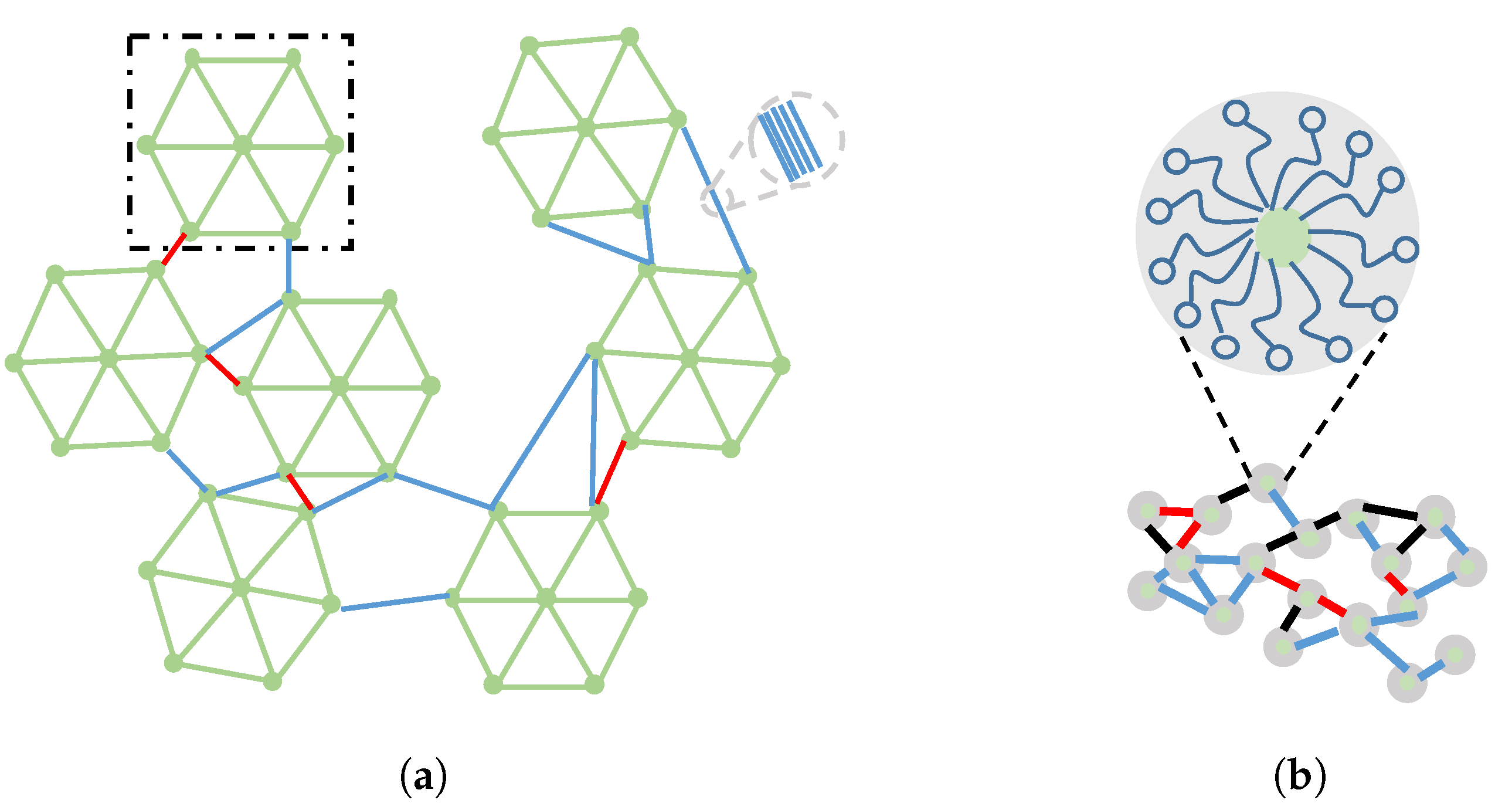
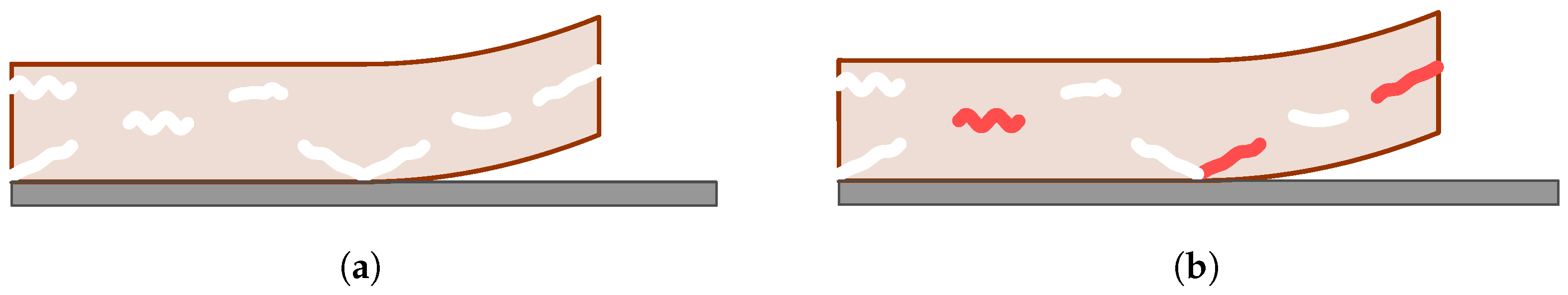
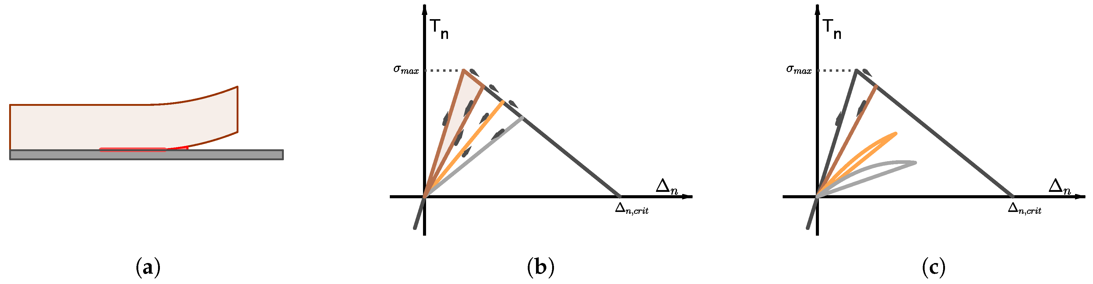
4. Cohesive Models of Crack Growth and Healing

Cohesive models bridge the gap between fracture mechanics and continuum damage mechanics. The fracture is treated explicitly but as a segment of small width embedded in the intact material (see Figure 3a). The evolution of the fracture is governed by the relation between the traction T and displacement jump Δ vectors at the surfaces of the fracture, given by the softening function (see Figure 3b,c) [47].
To the author’s knowledge, the first attempt to use cohesive models in the context of self-healing materials is due to Maiti and co-workers [48,49,50]. Maiti and Geubelle [48] first adapted a cohesive damage model to include fatigue fracture. A bilinear, rate independent and damage dependent softening function was considered for Mode I loading (see Figure 3b):
T n = d 1 d σ m a x d i n i t Δ n Δ n , c r i t
where T n and Δ n denote the normal components of the traction and displacement jump vectors at the surface of the cohesive fracture, σ m a x denotes the tensile strength of the material and Δ n , c r i t denotes the critical displacement jump. Equation (24) incorporates a scalar damage variable d that accounts for the monotonic degradation of the loading capacity of the cohesive fracture: d = 1 represents no damage and corresponds with Δ n = 0 , whereas d = 0 represents complete failure and corresponds with Δ n = Δ n , c r i t . The value d i n i t 1 is used to define the slope in the first section of the T n Δ n curve. The effects of fatigue were incorporated as an exponential decay of the instantaneous cohesive stiffness, k c = d T n d Δ n , with the number of loading cycles:
d k c d t = γ ( N f ) k c d Δ n d t , if d Δ n d t > 0 0 , otherwise
where N f denotes the number of loading cycles after damage initiation and γ is power law. The evolution law Equation (25) establishes that the cohesive stiffness is degraded during loading, and remains unchanged during unloading (see Figure 3c). Healing effects were incorporated by the inclusion of a rigid wedge in the rear of the crack tip [49]. The thickness and mechanical strength of the wedge shall be interpreted—at this point—as the outcome of the healing events taking place during the resting period between consecutive loading steps. The interaction between the wedge and the host material was formulated through the Hertz-Signorini-Moreau law for contact, that imposes no tension and no interpenetration between the contacting surfaces. The presence of the wedge means that the closure of the crack cannot be fully attained during unloading, and reduces the effective stress intensity factor. This results in the retardation of crack growth when loading is resumed. Computational results show that the retardation effect is increased with the thickness of the wedge, but also when the wedge is formed next to the crack tip or at shorter crack lengths. These results clearly indicate the competition between healing and crack growth dynamics, and hence only fast enough healing mechanisms can be successful.
The healing kinetics (given by the polymerization of dicyclopentadiene (DCPD)) were considered in [50]. Molecular dynamics simulation of DCPD structures were used to fit a phenomenological evolution law of for degree of curing of the wedge, α = α ( t ) [ 0 , 1 ] , based on the Prout-Tompkins reaction kinetics:
d α d t = A ( T ) ( 1 α ) n α m
where A ( T ) is a temperature dependent Arrhenius-type multiplicative factor, and n, m are the exponents fitted to molecular dynamics simulations. The mechanical properties of the polymerized DCPD structure were also obtained from the molecular dynamics simulation and correlated to the curing degree α . Finally, a phenomenological law relating the wedge thickness and the curing degree was proposed to further investigate the competition between the healing and crack growth kinetics. The simulations in [50] supplement those in [49] in the sense that the rest periods can be included in the discussion. Thus, crack growth is inhibited only at fast healing kinetics, and for a prescribed healing kinetics, better results are obtained for longer rest periods.
Ponnusami et al. [51] apply a cohesive damage model to analyze the effects of repeated healing events in the mechanical performance of the material. Following the same notation as in [51], we have that the first loading cycle induces a damage D [ 1 ] ( 0 ) in the original material that can be estimated as the ratio of the dissipated energy G d and the cohesive energy G c , D [ 1 ] ( 0 ) = G d G c . Recall that G d is computed as the area enclosed by the loading-unloading cycle, whereas G c is the area enclosed by the T n Δ n curve (see 
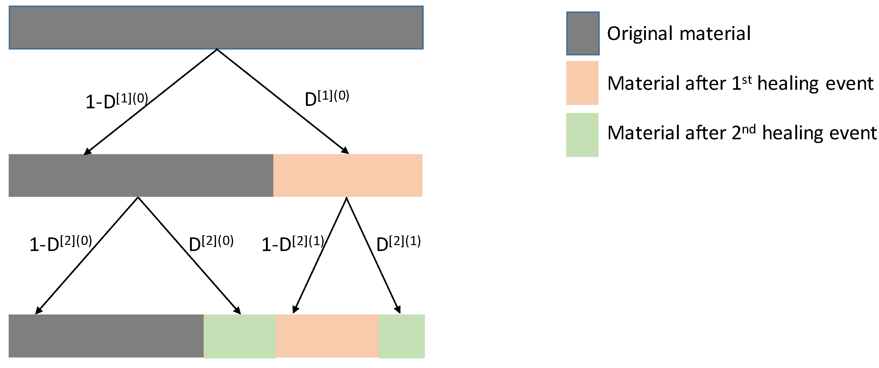
Figure 3b). If one assumes that all the damage produced in this first loading-unloading cycle is healed in the subsequent resting period, the outcome of the first damage-healing cycle is a composite of two materials: the original one (in a weighted ratio of w [ 1 ] ( 0 ) = 1 D [ 1 ] ( 0 ) ) and the healed one (in a weighted ratio of w [ 1 ] ( 1 ) = D [ 1 ] ( 0 ) ) (see Figure 4). The traction-separation curve of the constituents is constructed as a shifted version of the traction-separation curve of the original material, bearing in mind the following considerations. The crack opening is partly reduced by the healing event in the original material, whereas the healed material is created free of tension. A new loading-unloading cycle on this composite material will introduce two new damage parameters ( D [ 2 ] ( 0 ) relative to the original material, D [ 2 ] ( 1 ) relative to the healed material). The resting period after the second loading step will heal the damages and introduce a new constituent to the composite material: the material that is healed in the second period. The weighted fractions of the constituents after two healing events are, respectively, w [ 2 ] ( 0 ) = ( 1 D [ 1 ] ( 0 ) ) ( 1 D [ 2 ] ( 0 ) ) , w [ 2 ] ( 1 ) = D [ 1 ] ( 0 ) ( 1 D [ 2 ] ( 0 ) ) and w [ 2 ] ( 2 ) = ( 1 D [ 1 ] ( 0 ) ) D [ 2 ] ( 0 ) + D [ 1 ] ( 0 ) D [ 2 ] ( 0 ) (see Figure 4). The fracture energy of the composite material is computed as the weighted average of the fracture energies of its constituents. This idea can be reproduced for as many loading-unloading cycles as desired, keeping in mind that each rest period introduces a new constituent material. The model furthermore allows the definition of specific fracture strength for each constituent of the composite material, and therefore the incorporation of the healing history in the performance of the material. Results clearly demonstrate the dependence of the load bearing capacity of the material on the mechanical properties of the healed material. The load carrying capacity decreases with the decrease in the strength and fracture energy of the healed material(s). Furthermore, results also indicate a deterioration of the load carrying capacity when the degree of crack filling reduces. Ponnusami et al. [51] interpret the filling efficiency as a geometrical factor (i.e., the ratio of the crack volume filled with healing agent). However, in a fully coupled healing model, the filling efficiency should be deduced from the the mobilization and reaction of the healing agents.

5. Mobilization of Healing Agents

A critical point in extrinsic self-healing mechanisms is the activation of the healing agents. This can occur by the rupture (or dissolution) of the encapsulation systems or by the ingress of external species (such as oxygen or moisture) into the coating matrix. Computational calculations of the stress distribution around the capsules reveal that an evolving crack will not be attracted to capsules with a higher stiffness than that of the host matrix [15]. This observation has been further refined by means of computational approaches based on cohesive formulations of the capsule-matrix interface [52,53]. Using intensive parametric analyses, these works demarcate the basic material parameters (such as capsule to matrix stiffness or fracture strength ratios [52] and capsule thickness to radio ratio [53]) that allow to identify suitable matrix-capsule systems. The dissolution of encapsulated systems has been modeled as a phase transformation under equilibrium conditions [54].
On the other hand, the activation of healing agents by the ingress of external species—and the subsequent transport of the healing agents to the crack site—is strongly influenced by the interaction between the polymeric matrix and the diffusing species [55,56,57,58,59,60]. In the remainder of this section, the activation and transport of corrosion inhibitors will be used as an illustrative example. The interest of this mechanism rests on the variability of leaching behaviors reported in the literature [57,58,59,60,61,62]. Although the discussed models will focus on the basic steps leading to the recovery of the corrosion protection functionality, the principles upon which they are built can be easily translated to extrinsic self-healing mechanisms of coating barrier restoration. Note that differences will arise on the reaction mechanism that the activated and/or mobilized healing agents undergo at or in the vicinity of the scratch (such as the precipitation of solid phases [18] or the volumetric expansion of hydrophilic phases [12,21,22]). In the remainder of this section, the terms corrosion inhibitor and healing agent are interchangeable.
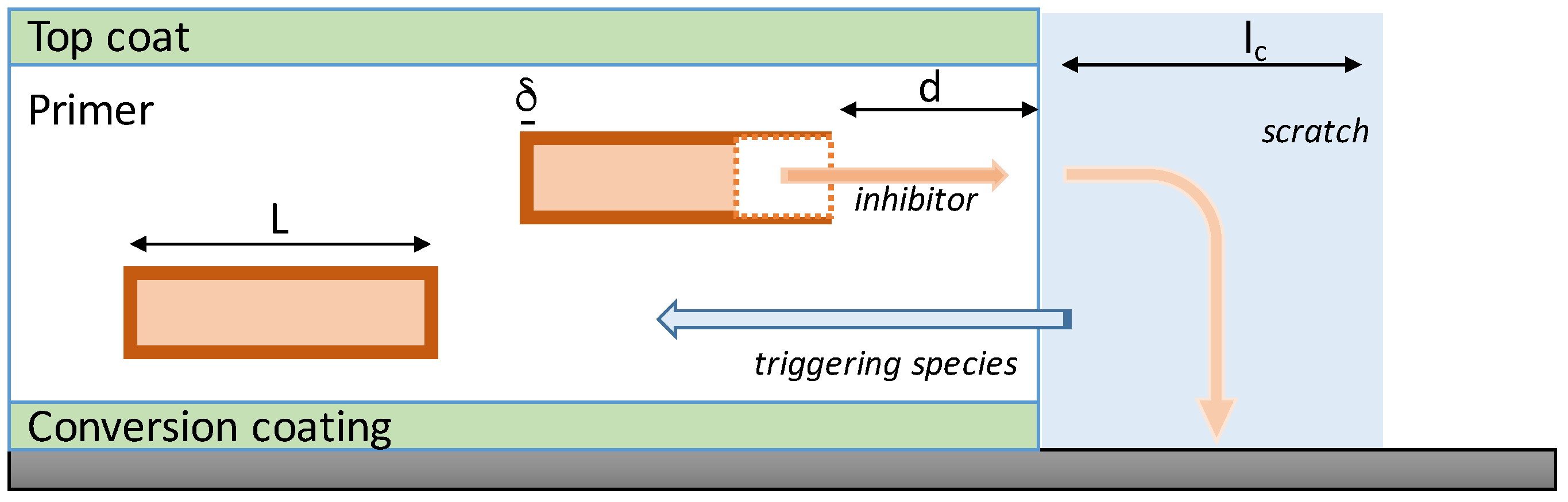
Organic coatings loaded with carriers of corrosion inhibitors prevent the onset of electrochemical corrosion after the barrier functionality of the coating is lost (see Figure 5). The polymeric matrix interacts with the transport of both the release-triggering and the inhibitor species [55,56]. Moisture uptake in neat vynil ester resins has been proved to follow a Fickian behavior (i.e., the mass of absorbed water is proportional with t 1 / 2 until saturation, where t denotes the immersion time). However, Drozdov et al. [56] extended this observation with the inclusion of montmorillonite clay nanoparticles in the vynil ester matrix, and obtained uptake curves that deviate from those of Fickian diffusion. The clay fraction was found to be a critical parameter, having a clear effect on the moisture diffusivity and rate of adsorption. These observations were modelled by means of a system of differential equations that coupled the evolution of two different forms of water concentrations: the concentration of mobile (penetrant) water n and the concentration of immobilized water (water molecules bounded at the clay surface) n 1 , based on mass conservation principles:
n t = x D n x n 1 t
n 1 t = k n ( n 1 0 n 1 )
D denotes the diffusion rate of mobile water, k the rate of adsorption of water molecules and n 1 0 the number of sites on the clay particle surface where the moisture molecules can bind (i.e., n 1 0 n 1 denotes the number of unoccupied sites where a water molecule can be immobilized). Drozdove et al. [56] use this basic model to correlate the dependence of D and k on the content of clay nanoparticles within the matrix, obtaining a decrease on both rates with the content of clay nanoparticles.
Accurate modeling of corrosion reactions at the exposed substrate shall involve the electrochemical reactions at the cathode and the anode, the hydrolysis reactions of the substrate and the release and transport of inhibitors. The former chemical reactions are formulated in terms of mass conservation of the chemical species, where the transport terms take into account the contribution of both random dispersal (i.e., diffusion) and bias transport induced by the potential, and the charge neutrality of the solution [61,63]. The release of inhibitors, on the other hand, remains not fully understood and is frequently disregarded. Wang et al. [61] adopted an intermediate approach and considered the presence of inhibitors though a phenomenological law formulated in terms of the pH in the solution, which can be deduced from the evolution of the chemical species.
The gap between the previously discussed class of models rests on the actual transport and release of the corrosion inhibitors from the coating. Recently, two different mathematical models [54,64] have been proposed to address the reasons behind the observed non-Fickian release of inhibitors in different coating-inhibitor systems [59,60]. The main difference in these works rests on how the inhibitors within the matrix are idealized: Javierre et al. [54] consider the role that a certain distribution of encapsulated inhibitor particles may have on the release kinetics (see Figure 5), whereas Tabor and Warszynski [64] consider the inhibitors to be homogeneously distributed throughout the coating.
In the case of a distributed configuration of particles, the release of the inhibitors requires (1) the ingress of a release-triggering substance (for instance moisture), (2) the rupture or dissolution of the capsule, and (3) the dissolution of the inhibitor particle and transport of the inhibitor compounds to the scratch (see Figure 5). Javierre et al. [54] model the transport steps by Fick’s second law, and the dissolution steps as binary Stefan problems [
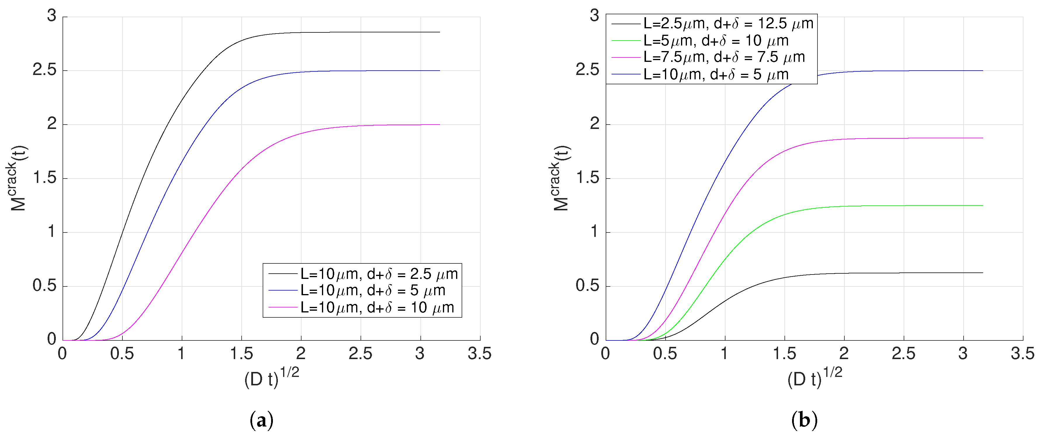
65]. The mathematical formulation of the Stefan problems combines Fick’s second law in a time-dependent domain with a mass conservation argument to obtain the velocity of the moving interface (i.e., the moving boundary of the dissolving particle). If we assume planar axial symmetry, the evolution of the inhibitor concentration c released from the dissolution of an isolated particle is given by:
c ( x , t ) = c p a r t , for 0 x < l ( t ) ( inside the particle )
c ( x , t ) = c s o l , at x = l ( t ) ( at the particle-coating interface )
c t ( x , t ) = x D c x ( x , t ) , for l ( t ) < x < l e n d ( in the coating and the scratch )
where the velocity of the particle-coating interface is given by:
d l d t ( t ) = D c p a r t c s o l c x ( l ( t ) , t )
For the sake of the comparison with [64], it should be noted here that the model assumes that the coating-scratch interface is in equilibrium (i.e., the same solubility is imposed at both sides of the coating-scratch interface). Note furthermore that with the current notation, the origin of coordinates has been located at the left side of the particle, and then the coating-scratch surface is located at x = L + δ + d (see Figure 5). Then, the mass of the inhibitor released into the scratch space can be computed from the concentration c, taking into account the scratch width ( l c ) and its distance to the origin of coordinates:
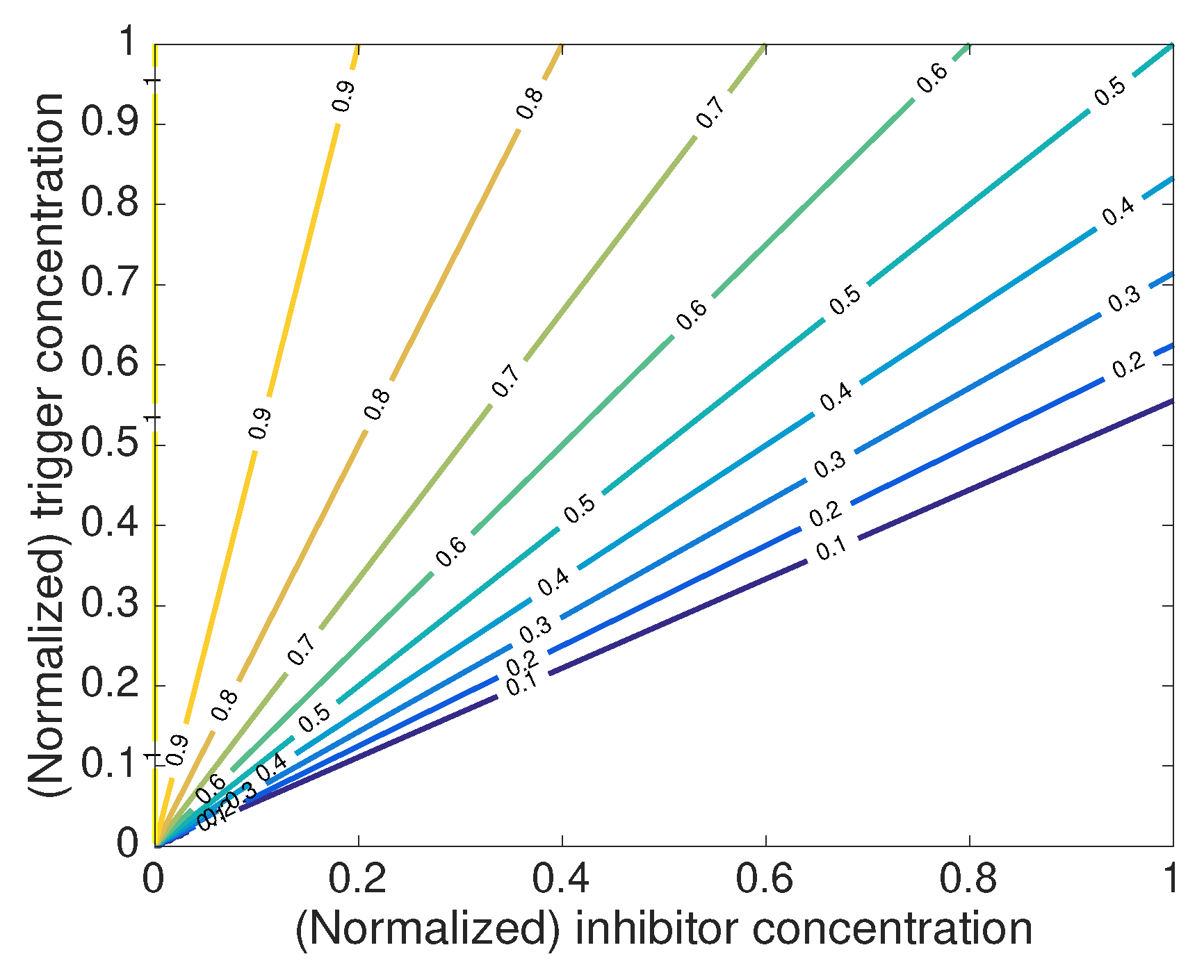
M c r a c k ( t ) = 0 l c c ( L + δ + d + x , t ) d x
The plot of M c r a c k ( t ) for different distances L + δ + d is presented in Figure 6a,b. Both the amount of mass leached into the scratch and the rate at which the leaching occurs is affected by the size of the particle and its distance to the scratch. Note furthermore that the time lapse required for the mass of a certain particle to reach the scratch is also affected by the specific values of the distances.
The central idea of the model presented in [54] is to analyze how the mass M i c r a c k leached from particle i combines with the mass leached from other particles, and how their combination can lead to an overall mass M t o t a l c r a c k ( t ) that presents a behavior in time different from t 1 / 2 (i.e., different to Fickian). The overall mass M t o t a l c r a c k ( t ) is computed from:
M t o t a l c r a c k ( t ) = i M i c r a c k ( t θ i )
where the times θ i account for the activation time of particle i. Javierre et al. [54] record the mass M i c r a c k of each particle in different configurations, and use the activation times θ i to fit M t o t a l c r a c k to different leaching kinetics. They observe that leaching kinetics proportional to t α —with α [ 0.5 , 1 ] —can be obtained by this procedure. They furthermore derive self-similar solutions allowing to relate the activation times θ i with the transport of the release-triggering species and the dissolution of the capsule. Thus, a tool is provided to evaluate a desired leaching kinetics against the diffusion coefficients and saturation levels of the release-triggering species and the capsule compounds.
Tabor and Warszynski [64] also considered the interaction between a release-triggering species and the inhibitor species itself. The evolution of theses species was formulated in terms of diffusion equations for each species at each domain (scratch and coating). Different solubilities are considered for each species in each domain, and hence the boundary conditions on the scratch-coating interface are formulated in terms of the corresponding partition coefficients. Continuity of the normal fluxes across the scratch-coating interface are imposed, and hence the total mass of the system is conserved. Tabor and Warszynski also consider the existence of reservoirs of inhibitors within the matrix, but do not treat them explicitly (as in [54]). Instead, they introduce a new variable that represent the homogenized version of the dispersed corrosion inhibitor particles. At the scratch domain, the triggering species is assumed to remain at a constant level, and the inhibitor species is transported by standard diffusion. Of interest to the present discussion is the coupling of the different species within the coating domain, and hence the governing equations will be reproduced here. Without loss of generality, we denote by c T , c I and c R the concentration of the triggering species, the (active) inhibitor and the (inactive) inhibitor. The inactive inhibitor refers to the inhibitors stored at the reservoirs. Again under planar symmetry, the coupling of these species within the coating domain is given by:
c T t = x D T c T x
c I t = x D I c I x + P ( c I , c T , c R )
c R t = P ( c I , c T , c R )
where the function P establishes the nonlinear coupling between the activation of inhibitors from the reservoirs:
P ( c I , c T , c R ) = b 1 c I a c T , if c I a c T and c R > 0 0 , otherwise
The function P establishes the activation rate of the stored inhibitors (see Figure 7). This activation depends on actual levels of both the inhibitor and the triggering species, and consequently, on their transport within the coating (Equations (34) and (35)) and within the scratch. The reservoirs are not extinguished and for a fixed concentration of the inhibitor, the activation of more inhibitors only occurs when the concentration of the trigger exceeds the threshold level c I / a . On the other hand, as inhibitors are been transported towards the scratch, i.e., removed from the coating, the activation rate gradually decreases.
Under these basic principles, Tabor and Warszynski [64] report release kinetics proportional to t α with α [ 0.5 , 1.5 ] . By means of parametric analyses, the authors demonstrate that the exponent α depends on the rate parameter b in Equation (37) and the partition coefficient of the inhibitor (i.e., the ratio between the solubilities of the inhibitor at the solution in the scratch and within the coating matrix).

6. Discussion

A self-healing mechanism, to be successful, requires the timely activation, mobilization and reaction of the healing agents. In the course of these stages, both mechanical stress and external environment may play an active role. This paper reviews four modeling frameworks that address the healing mechanisms from different perspectives: the dynamic adaptation of the polymeric network (Section 2), the degradation and recovery of the mechanical properties of the coating (Section 3 and Section 4) and the transport and reaction of species within the matrix (Section 5).
Dynamic polymeric networks based on reversible chemistries lead to coating systems that actively react to externally applied stimulus such as changes in temperature [5,10] and exposition to UV light [12]. The incorporation of reversible bonds enhances polymer flow, but at the expense of its strength. Moreover, the external stimulus that triggers the self-healing response depends on the specific bond chemistry. Thus, approaches using retro Diels-Alder reactions require higher activation temperatures than systems based on disulfide bonds [6]. The Bell model has been generalized to incorporate the contributions of both temperature and stress on the process of bond formation and rupture [26], which allows the evaluation of specific bond kinetics provided an accurate knowledge of the involved parameters. While these are not made available, the best option to calibrate the model continues to be its fit to measurable macroscopic features [33]. The incorporation of dynamic bond kinetics into complex network configurations allows the evaluation of the macroscopic deformation [26,29] and the load bearing capacity [33] for each particular bond chemistry. If polymer diffusion is also taken into account, the capabilities of the predictive model include the adhesion of interfaces [33] and, therefore, a full characterization of the self healing response in terms of bond chemistry, but also cross-linker density [32] and polymer chain length [33].
Models based on the continuum damage healing mechanics offer the possibility to couple the healing mechanisms at the molecular scale with the (homogenized) macroscopic description of the material. The complexity of this approach arises from the need for an accurate formulation of the evolution laws for the damage and healing internal variables [43]. Phenomenological laws in terms of the mass of healing agents [42] and the experimentally measured healing efficiencies [39] have been used to reproduce the response to mechanical load in polymeric and composite materials. Recently, a more elaborated model that couples the closure of the scratch by shape memory polymers with the diffusion of the self-healing agent across the interface has been formulated in [46]. Extrinsic self-healing mechanisms, however, seem to remain elusive from these approaches. On the other hand, cohesive formulations of the evolving crack ease the treatment of damage and healing. Relatively straight forward formulations of the traction-displacement function allow to capture changes in the mechanical performance of materials due to fatigue and healing [48,50] and repeated healing events [51], though the actual healing step is not taken into account (a phenomenological law for the curing degree of the polymerization of liquid healing agents was used in [50] to establish the dimensions and mechanical properties of the healed material). Therefore, it seems clear that the path to improve the predictive power of these models demands the incorporation of the transport and reaction of healing agents, either from the capillary flow of liquid agents [66] or the diffusive transport and reaction of dissolved species [54]. On the other hand, cohesive models have been proved to be very useful in the evaluation of encapsulation systems [52,53].
In the case of extrinsic self-healing mechanisms activated by the ingress of external species, such as those in thermal barrier coating [18,19] or expandable systems [21,22], the models discussed in Section 5 focus on the interaction between the coating matrix and both the external triggering species (oxygen, moisture) and the internal healing agents through systems of diffusion-reaction reactions. This interaction leads to diffusion profiles that depart from Fickian diffusion, for both the ingress of moisture [22,56] and the transport of the healing agent [59,60], that are not fully understood. The models do predict an anomalous diffusion behavior and provide a framework to analyze transport kinetics faster than Fickian. The observed anomalous diffusion behavior can be traced back to the distribution of the encapsulated healing agents, the capsule dissolution kinetics and the moisture diffusion within the coating matrix [54] and to the rate of healing agent activation and differences in the solubilities across the crack surface [64]. Despite the potential that these models present to explain part of the spectrum of leaching kinetics of corrosion inhibitors, and to evaluate the potential performance of specific inhibitor-coating matrix systems, a thorough calibration with experimental data is necessary to surpass the present qualitative descriptions. Additionally, a possible extension that could be implemented in the presented diffusion-reaction models is the incorporation of differential equations of fractional order [67]. This would introduce the anomalous diffusion of the external triggering species and/or the healing species and possibly broaden the range of leaching kinetics that can be predicted. Another consideration that could deeper the knowledge of the interactions between the matrix and the diffusing species may be to take into account the porous nature of the coating matrix [68,69]. Such a modification would allow to treat the different compounds in the material as different phases of the porous material [70], but also to incorporate the effects of pore fluid (and/or gas) pressure and flow and of the evolving porosity on the transport of dissolved chemical compounds. At least from a conceptual point of view, such phenomena could have an important outcome in the performance of corrosion protection coatings and expanding hydrogels.

Funding

This research was funded by the Ministerio de Economía, Industria y Competitividad, Gobierno de España (No. MTM2016-75139-R).

Acknowledgments

The author gratefully acknowledges the support of Diputación General de Aragón through the research group with reference E24_17R.

Conflicts of Interest

The authors declare no conflict of interest. The founding sponsors had no role in the design of the study; in the collection, analyses, or interpretation of data; in the writing of the manuscript, or in the decision to publish the results.

References

  1. Van der Zwaag, S. Self Healing Materials: An Alternative Approach to 20 Centuries of Materials Science; Springer: Dordrecht, The Netherlands, 2007. [Google Scholar]
  2. Ghosh, S.K. Self-Healing Materials: Fundamentals, Design Strategies, and Applications; Wiley-VCH Verlag GmbH & Co. KGaA: Weinheim, Germany, 2009. [Google Scholar]
  3. Chen, X.X.; Dam, M.A.; Ono, K.; Mal, A.; Shen, H.B.; Nutt, S.R.; Sheran, K.; Wudl, F. A thermally re-mendable cross-linked polymeric material. Science 2002, 295, 1698–1702. [Google Scholar] [CrossRef] [PubMed]
  4. Turkenburg, D.H.; Durant, Y.; Fischer, H.R. Bio-based self-healing coatings based on thermo-reversible Diels-Alder reaction. Prog. Organ. Coat. 2017, 111, 38–46. [Google Scholar] [CrossRef]
  5. Brancart, J.; Verhelle, R.; Mangialetto, J.; Assche, G.V. Coupling the microscopic healing behaviour of coatings to the thermoreversible diels-alder network formation. Coatings 2019, 9, 13. [Google Scholar] [CrossRef]
  6. Canadell, J.; Goossens, H.; Klumperman, B. Self-healing materials based on disulfide links. Macromolecules 2011, 44, 2536–2541. [Google Scholar] [CrossRef]
  7. Amamoto, Y.; Otsuka, H.; Takahara, A.; Matyjaszewski, K. Self-healing of covalently cross-linked polymers by reshuffling thiuram disulfide moieties in air under visible light. Adv. Mater. 2012, 24, 3975–3980. [Google Scholar] [CrossRef]
  8. Yoon, J.A.; Kamada, J.; Koynov, K.; Mohin, J.; Nicolaÿ, R.; Zhang, Y.; Balazs, A.C.; Kowalewski, T.; Matyjaszewski, K. Self-healing polymer films based on thiol–disulfide exchange reactions and self-healing kinetics measured using atomic force microscopy. Macromolecules 2012, 45, 142–149. [Google Scholar] [CrossRef]
  9. AbdolahZadeh, M.; Esteves, A.C.C.; van der Zwaag, S.; Garcia, S.J. Healable dual organic-inorganic crosslinked sol-gel based polymers: Crosslinking density and tetrasulfide content effect. J. Polym. Sci. Part A Polym. Chem. 2014, 52, 1953–1961. [Google Scholar] [CrossRef]
  10. Abdolah Zadeh, M.; van der Zwaag, S.; Garcia, S.J. Adhesion and long-term barrier restoration of intrinsic self-healing hybrid sol-gel coatings. ACS Appl. Mater. Interfaces 2016, 8, 4126–4136. [Google Scholar] [CrossRef]
  11. Cordier, P.; Tournilhac, F.; Soulié-Ziakovic, C.; Leibler, L. Self-healing and thermoreversible rubber from supramolecular assembly. Nature 2008, 451, 977–980. [Google Scholar] [CrossRef]
  12. Amamoto, Y.; Kamada, J.; Otsuka, H.; Takahara, A.; Matyjaszewski, K. Repeatable photoinduced self-healing of covalently cross-linked polymers through reshuffling of trithiocarbonate units. Angew. Chem. Int. Ed. 2011, 50, 1660–1663. [Google Scholar] [CrossRef]
  13. Meng, H.; Li, G. A review of stimuli-responsive shape memory polymer composites. Polymer 2013, 54, 2199–2221. [Google Scholar] [CrossRef]
  14. Lutz, A.; van den Berg, O.; Wielant, J.; De Graeve, I.; Terryn, H. A multiple-action self-healing coating. Front. Mater. 2016, 2, 73. [Google Scholar] [CrossRef]
  15. White, S.R.; Sottos, N.R.; Geubelle, P.H.; Moore, J.S.; Kessler, M.R.; Sriram, S.R.; Brown, E.N.; Viswanathan, S. Autonomic healing of polymer composites. Nature 2001, 409, 794–797. [Google Scholar] [CrossRef] [PubMed]
  16. Cho, S.H.; White, S.R.; Braun, P.V. Self-healing polymer coatings. Adv. Mater. 2009, 21, 645–649. [Google Scholar] [CrossRef]
  17. Samadzadeh, M.; Boura, S.H.; Peikari, M.; Ashrafi, A.; Kasiriha, M. Tung oil: An autonomous repairing agent for self-healing epoxy coatings. Prog. Org. Coat. 2011, 70, 383–387. [Google Scholar] [CrossRef]
  18. Nozahic, F.; Monceau, D.; Estournès, C. Thermal cycling and reactivity of a MoSi2/ZrO2 composite designed for self-healing thermal barrier coatings. Mater. Des. 2016, 94, 444–448. [Google Scholar] [CrossRef]
  19. Nozahic, F.; Estournès, C.; Carabat, A.L.; Sloof, W.G.; van der Zwaag, S.; Monceau, D. Self-healing thermal barrier coating systems fabricated by spark plasma sintering. Mater. Des. 2018, 143, 204–213. [Google Scholar] [CrossRef]
  20. Sugama, T.; Gawlik, K. Self-repairing poly(phenylenesulfide) coatings in hydrothermal environments at 200 °C. Mater. Lett. 2003, 57, 4282–4290. [Google Scholar] [CrossRef]
  21. Miccichè, F.; Fischer, H.; Varley, R.; van der Zwaag, S. Moisture induced crack filling in barrier coatings containing montmorillonite as an expandable phase. Surf. Coat. Technol. 2008, 202, 3346–3353. [Google Scholar] [CrossRef]
  22. Saini, V.; von Tapavicza, M.; Eloo, C.; Braesch, K.; Wack, H.; Nellesen, A.; Schmidt, A.M.; Garcia, S.J. Superabsorbent polymer additives for repeated barrier restoration of damaged powder coatings under wet-dry cycles: A proof-of-concept. Prog. Org. Coat. 2018, 122, 129–137. [Google Scholar] [CrossRef]
  23. Esteves, A.C.C.; Lyakhova, K.; van der Ven, L.G.J.; van Benthem, R.A.T.M.; de With, G. Surface segregation of low surface energy polymeric dangling chains in a cross-linked polymer network investigated by a combined experimental-simulation approach. Macromolecules 2013, 46, 1993–2002. [Google Scholar] [CrossRef]
  24. Lyakhova, K.; Esteves, A.C.C.; van de Put, M.W.P.; van der Ven, L.G.J.; van Benthem, R.A.T.M.; de With, G. Simulation-experimental approach to investigate the role of interfaces in self-replenishing composite coatings. Adv. Mater. Interfaces 2014, 1, 1400053. [Google Scholar] [CrossRef]
  25. Esteves, A.C.C.; Lyakhova, K.; van Riel, J.M.; van der Ven, L.G.J.; van Benthem, R.A.T.M.; de With, G. Self-replenishing ability of cross-linked low surface energy polymer films investigated by a complementary experimental-simulation approach. J. Chem. Phys. 2014, 140, 124902. [Google Scholar] [CrossRef] [PubMed]
  26. Kolmakov, G.V.; Matyjaszewski, K.; Balazs, A.C. Harnessing labile bonds between nanogel particles to create self-healing materials. ACS Nano 2009, 3, 885–892. [Google Scholar] [CrossRef] [PubMed]
  27. Duki, S.F.; Kolmakov, G.V.; Yashin, V.V.; Kowalewski, T.; Matyjaszewski, K.; Balazs, A.C. Modeling the nanoscratching of self-healing materials. J. Chem. Phys. 2011, 134, 084901. [Google Scholar] [CrossRef] [PubMed]
  28. Salib, I.G.; Kolmakov, G.V.; Gnegy, C.N.; Matyjaszewski, K.; Balazs, A.C. Role of parallel reformable bonds in the self-healing of cross-linked nanogel particles. Langmuir 2011, 27, 3991–4003. [Google Scholar] [CrossRef] [PubMed]
  29. Iyer, B.V.S.; Yashin, V.V.; Kowalewski, T.; Matyjaszewski, K.; Balazs, A.C. Strain recovery and self-healing in dual cross-linked nanoparticle networks. Polym. Chem. 2013, 4, 4927–4939. [Google Scholar] [CrossRef]
  30. Iyer, B.V.S.; Salib, I.G.; Yashin, V.V.; Kowalewski, T.; Matyjaszewski, K.; Balazs, A.C. Modeling the response of dual cross-linked nanoparticle networks to mechanical deformation. Soft Matter 2013, 9, 109–121. [Google Scholar] [CrossRef]
  31. Hamer, M.J.; Iyer, B.V.S.; Yashin, V.V.; Kowalewski, T.; Matyjaszewski, K.; Balazs, A.C. Modeling polymer grafted nanoparticle networks reinforced by high-strength chains. Soft Matter 2014, 10, 1374–1383. [Google Scholar] [CrossRef]
  32. Wang, Q.; Gao, Z.; Yu, K. Interfacial self-healing of nanocomposite hydrogels: Theory and experiment. J. Mech. Phys. Solids 2017, 109, 288–306. [Google Scholar] [CrossRef]
  33. Yu, K.; Xin, A.; Wang, Q. Mechanics of self-healing polymer networks crosslinked by dynamic bonds. J. Mech. Phys. Solids 2018, 121, 409–431. [Google Scholar] [CrossRef]
  34. Zhao, X. A theory for large deformation and damage of interpenetrating polymer networks. J. Mech. Phys. Solids 2012, 60, 319–332. [Google Scholar] [CrossRef]
  35. De Gennes, P.G. Reptation of a polymer chain in the presence of fixed obstacles. J. Chem. Phys. 1971, 55, 572–579. [Google Scholar] [CrossRef]
  36. Wang, Q.; Gossweiler, G.R.; Craig, S.L.; Zhao, X. Mechanics of mechanochemically responsive elastomers. J. Mech. Phys. Solids 2015, 82, 320–344. [Google Scholar] [CrossRef]
  37. Chagnon, G.; Verron, E.; Marckmann, G.; Gornet, L. Development of new constitutive equations for the Mullins effect in rubber using the network alteration theory. Int. J. Solids Struct. 2006, 43, 6817–6831. [Google Scholar] [CrossRef]
  38. Barbero, E.J.; Greco, F.; Lonetti, P. Continuumdamage-healing mechanics with application to self-healing composites. Int. J. Damage Mech. 2005, 14, 51–81. [Google Scholar] [CrossRef]
  39. Barbero, E.J.; Ford, K.J.; Mayugo, J.A. Modeling self-healing of fiber-reinforced polymer-matrix composites with distributed damage. In Self-Healing Materials: Self-Healing Materials: Fundamentals, Design Strategies, and Applications; Ghosh, S.K., Ed.; Wiley-VCH Verlag GmbH & Co. KGaA: Weinheim, Germany, 2009; pp. 267–283. [Google Scholar]
  40. Oucif, C.; Mauludin, L. Continuum damage-healing and super healing mechanics in brittle materials: A state-of-the-art review. Appl. Sci. 2018, 8, 2350. [Google Scholar] [CrossRef]
  41. Voyiadjis, G.Z.; Kattan, P.I. A comparative study of damage variables in continuum damage mechanics. Int. J. Damage Mech. 2009, 18, 315–340. [Google Scholar] [CrossRef]
  42. Voyiadjis, G.; Shojaei, A.; Li, G.; Kattan, P. Continuum damage-healing mechanics with introduction to new healing variables. Int. J. Damage Mech. 2011, 21, 391–414. [Google Scholar] [CrossRef]
  43. Darabi, M.K.; Al-Rub, R.K.A.; Little, D.N. A continuum damage mechanics framework for modeling micro-damage healing. Int. J. Solids Struct. 2012, 49, 492–513. [Google Scholar] [CrossRef]
  44. Voyiadjis, G.Z.; Shojaei, A.; Li, G.; Kattan, P.I. A theory of anisotropic healing and damage mechanics of materials. Proc. Math. Phys. Eng. Sci. 2012, 468, 163–183. [Google Scholar] [CrossRef]
  45. Al-Rub, R.K.A.; Darabi, M.K.; Little, D.N.; Masad, E.A. A micro-damage healing model that improves prediction of fatigue life in asphalt mixes. Int. J. Eng. Sci. 2010, 48, 966–990. [Google Scholar] [CrossRef]
  46. Shojaei, A.; Sharafi, S.; Li, G. A multiscale theory of self-crack-healing with solid healing agent assisted by shape memory effect. Mech. Mater. 2015, 81, 25–40. [Google Scholar] [CrossRef]
  47. Elices, M.; Guinea, G.V.; Gomez, J.; Planas, J. The cohesive zone model: Advantages, limitations and challenges. Eng. Fract. Mech. 2002, 69, 137–163. [Google Scholar] [CrossRef]
  48. Maiti, S.; Geubelle, P.H. A cohesive model for fatigue failure of polymers. Eng. Fract. Mech. 2005, 72, 691–708. [Google Scholar] [CrossRef]
  49. Maiti, S.; Geubelle, P.H. Cohesive modeling of fatigue crack retardation in polymers: Crack closure effect. Eng. Fract. Mech. 2006, 73, 22–41. [Google Scholar] [CrossRef]
  50. Maiti, S.; Shankar, C.; Geubelle, P.H.; Kieffer, J. Continuum and molecular-level modeling of fatigue crack retardation in self-healing polymers. J. Eng. Mater. Technol. 2006, 128, 595–602. [Google Scholar] [CrossRef]
  51. Ponnusami, S.A.; Krishnasamy, J.; Turteltaub, S.; van der Zwaag, S. A cohesive-zone crack healing model for self-healing materials. Int. J. Solids Struct. 2018, 134, 249–263. [Google Scholar] [CrossRef]
  52. Ponnusami, S.A.; Turteltaub, S.; van der Zwaag, S. Cohesive-zone modelling of crack nucleation and propagation in particulate composites. Eng. Fract. Mech. 2015, 149, 170–190. [Google Scholar] [CrossRef]
  53. Gilabert, F.A.; Garoz, D.; Van Paepegem, W. Macro- and micro-modeling of crack propagation in encapsulation-based self-healing materials: Application of XFEM and cohesive surface techniques. Mater. Des. 2017, 130, 459–478. [Google Scholar] [CrossRef]
  54. Javierre, E.; Garcia, S.J.; Mol, J.M.C.; Vermolen, F.J.; Vuik, C.; van der Zwaag, S. Tailoring the release of encapsulated corrosion inhibitors from damaged coatings: Controlled release kinetics by overlapping diffusion fronts. Prog. Org. Coat. 2012, 75, 20–27. [Google Scholar] [CrossRef]
  55. Batchelor, B. Leach models: Theory and application. J. Hazard. Mater. 1990, 24, 255–266. [Google Scholar] [CrossRef]
  56. Drozdov, A.D.; de Christiansen, J.; Gupta, R.K.; Shah, A.P. Model for anomalous moisture diffusion through a polymer-clay nanocomposite. J. Polym. Sci. Part B Polym. Phys. 2003, 41, 476–492. [Google Scholar] [CrossRef]
  57. Prosek, T.; Thierry, D. A model for the release of chromate from organic coatings. Prog. Org. Coat. 2004, 49, 209–217. [Google Scholar] [CrossRef]
  58. Howard, R.L.; Zin, I.M.; Scantlebury, J.D.; Lyon, S.B. Inhibition of cut edge corrosion of coil-coated architectural cladding. Prog. Org. Coat. 1999, 37, 83–90. [Google Scholar] [CrossRef]
  59. Furman, S.A.; Scholes, F.H.; Hughes, A.E.; Lau, D. Chromate leaching from inhibited primers: Part II: Modelling of leaching. Prog. Org. Coat. 2006, 56, 33–38. [Google Scholar] [CrossRef]
  60. Nazarov, A.; Thierry, D.; Prosek, T.; Le Bozec, N. Protective action of vanadate at defected areas of organic coatings on zinc. J. Electrochem. Soc. 2005, 152, B220–B227. [Google Scholar] [CrossRef]
  61. Wang, H.; Presuel, F.; Kelly, R.G. Computational modeling of inhibitor release and transport from multifunctional organic coatings. Electrochim. Acta 2004, 49, 239–255. [Google Scholar] [CrossRef]
  62. Zin, I.M.; Howard, R.L.; Badger, S.J.; Scantlebury, J.D.; Lyon, S.B. The mode of action of chromate inhibitor in epoxy primer on galvanized steel. Prog. Org. Coat. 1998, 33, 203–210. [Google Scholar] [CrossRef]
  63. Abodi, L.C.; DeRose, J.A.; Van Damme, S.; Demeter, A.; Suter, T.; Deconinck, J. Modeling localized aluminum alloy corrosion in chloride solutions under non-equilibrium conditions: Steps toward understanding pitting initiation. Electrochim. Acta 2012, 63, 169–178. [Google Scholar] [CrossRef]
  64. Tabor, Z.; Warszyński, P. Modeling dissolution controlled release of inhibitor from a damaged coating. Corros. Sci. 2014, 82, 290–296. [Google Scholar] [CrossRef]
  65. Javierre, E.; Vuik, C.; Vermolen, F.J.; van der Zwaag, S. A comparison of numerical models for one-dimensional Stefan problems. J. Comput. Appl. Math. 2006, 192, 445–459. [Google Scholar] [CrossRef]
  66. Gardner, D.; Jefferson, A.; Hoffman, A.; Lark, R. Simulation of the capillary flow of an autonomic healing agent in discrete cracks in cementitious materials. Cem. Concr. Res. 2014, 58, 35–44. [Google Scholar] [CrossRef]
  67. Metzler, R.; Klafter, J. The random walk’s guide to anomalous diffusion: A fractional dynamics approach. Phys. Rep. 2000, 339, 1–77. [Google Scholar] [CrossRef]
  68. Yabuki, A.; Nishisaka, T. Self-healing capability of porous polymer film with corrosion inhibitor inserted for corrosion protection. Corros. Sci. 2011, 53, 4118–4123. [Google Scholar] [CrossRef]
  69. Tyagi, P.; Deratani, A.; Bouyer, D.; Cot, D.; Gence, V.; Barboiu, M.; Phan, T.N.T.; Bertin, D.; Gigmes, D.; Quemener, D. Dynamic interactive membranes with pressure-driven tunable porosity and self-healing ability. Angew. Chem. Int. Ed. 2012, 51, 7166–7170. [Google Scholar] [CrossRef] [PubMed]
  70. Bluhm, J.; Specht, S.; Schröder, J. Modeling of self-healing effects in polymeric composites. Arch. Appl. Mech. 2014, 85, 1469–1481. [Google Scholar] [CrossRef]
Figure 1. Schematic representation of the dual cross-linked network: (a) Hexagonal particles, which can establish strong (black) and labile (blue) bonds with their neighbors; (b) Spherical particles, surrounded by a corona of distributed reactive polymer chains that establish bonds with their neighbors. Colors may indicate the type of bond and/or the number of bonds between the connected nodes.
Coatings 09 00122 g001
Figure 2. Schematic representation of the continuum damage-healing mechanics: (a) Partly damaged coating ( 0 < d < 1 ); (b) Damaged coating after the healing events: a new value d of the damage variable is obtained, with 0 < d < d and 0 < h < 1 . For the sake of the illustration, h = 1 represents full recovery of the damage and the healed microcracks are coloured in red.
Coatings 09 00122 g002
Figure 3. Schematic representation of cohesive models: (a) Illustration of the loss of adhesion at the coating-substrate interface; (b) Bi-linear traction-separation law. The arrows indicate the loading and unloading paths; and (c) Traction-separation law when the cohesive stiffness is degraded during loading.
Coatings 09 00122 g003
Figure 4. Schematic representation of the composite material after two healing events, which consists of the original material that has not been damaged by either of the two loading cycles, the material that is created after the first healing event and has not been damaged in the second loading cycle, and the material that is created in the second round of healing events and accounts for the damage in both the original material and in the material created by the first healing event.
Coatings 09 00122 g004
Figure 5. Schematic representation of the processes leading to the leaching of corrosion inhibitors from a damaged coating.
Coatings 09 00122 g005
Figure 6. Inhibitor mass leached into the scratch computed from Equations (28)–(33), c p a r t = 1 , c s o l = 0.7 , c 0 = 0 , D = 5 . (a) The particle size L is kept constant, and its distance to the scratch d + δ is varied. (b) The total distance L + d + δ is kept constant but the size of the particle L is varied.
Coatings 09 00122 g006
Figure 7. Contour lines of P ( c i , c t , c p ) / b for the whole range of values of the concentration c i of the inhibitor concentration and c t of the release-triggering species.
Coatings 09 00122 g007

