Article

Influence of Different Heat Treatment Temperatures on the Microstructure, Corrosion, and Mechanical Properties Behavior of Fe-Based Amorphous/Nanocrystalline Coatings

School of Materials Science and Engineering, Chang’an University, Xi’an 710061, China
*
Author to whom correspondence should be addressed.
Coatings 2019, 9(12), 858; https://doi.org/10.3390/coatings9120858
Submission received: 13 November 2019 / Revised: 5 December 2019 / Accepted: 11 December 2019 / Published: 14 December 2019

Abstract

:
Fe-based amorphous/nanocrystalline coatings with smooth, compact interior structure and low porosity were fabricated via supersonic plasma spraying (SPS). The coatings showed outstanding corrosion resistance in a 3.5% NaCl solution at room temperature. In order to analyze the effect of annealing treatment on the microstructure, corrosion resistance and microhardness, the as-sprayed coating was annealed for 1 h under different temperatures such as 350, 450, 550 and 650 °C, respectively. The results showed that the number of oxides and cracks in the coatings presented an obvious increase with increasing annealing temperature, and the corrosion resistance of the coatings showed an obvious reduction. However, the microhardness of coatings showed an important increase. The microhardness of the coating could reach 1018 HV when the heat treatment temperature reached 650 °C. The X-ray diffraction (XRD) results showed that there appeared a number of crystalline phases in the coating when the heat treatment temperature was at 650 °C. The crystalline phases led to the increase of the microhardness.

1. Introduction

As we know, Fe-based amorphous/nanocrystalline coatings are widely used in the oil and gas industry, building industry, biomedical implants and so on. Fe-based amorphous/nanocrystalline coatings have caused great attention due to their high corrosion resistance, outstanding anti-wear performances, excellent microhardness and low cost [1,2,3]. Nevertheless, the applications of the Fe-based amorphous/nanocrystalline coatings are often restricted by the low crystallization temperature. In order to manufacture satisfactory product, several thermal spraying technologies are used to fabricate the Fe-based amorphous/nanocrystalline coatings, such as arc spraying, supersonic plasma spraying, high-velocity air-fuel spraying (HVAF) and high-velocity oxy-fuel spraying (HVOF) [4,5,6,7,8]. The results from Guo et al. [9] showed that the average Vickers hardness of Fe–Cr–Nb–B amorphous/nanocrystalline coatings reach 890 ± 75 HV. The study from Botta et al. [10] found that Cr in the Fe-based amorphous alloys had a good positive influence on the corrosion resistance with the formation of a stable passive film. Furthermore, results from Zhou et al. [11] showed that the microhardness, poriness and thermostability of the coatings were related to the spraying power and Ar flow rate. In order to enhance the microhardness and anti-wear performances of the Fe-based amorphous/nanocrystalline coatings, some scholars add reinforcement particles, such as Al2O3, WC, TiN and so on into the coatings. The results showed that reinforced particles obviously improved the microhardness and anti-wear performances of the Fe-based amorphous/nanocrystalline coating [12,13,14,15,16].
In the thermal spraying technologies mentioned above, SPS has gradually caught the attention of more researchers. Compared with other spraying technologies [9,17], the faster particle velocity and higher temperature heat source contributes to acquiring more dense lamellar structure and less porosity Fe-amorphous coatings, which are important for the corrosion resistance of the coating.
In addition, heat treatment can also cause grain growth [17,18,19] which directly affects mechanical properties and corrosion resistance of coatings. In the previous studies, this series of changes of low Cr content Fe-based amorphous/nanocrystalline coatings had been reported by other researchers [20,21,22,23], but the effect of heat treatment on the high Cr content Fe-based amorphous/nanocrystalline coatings were rarely studied.
In this work, Fe-based amorphous/nanocrystalline coatings were fabricated by SPS. In the spraying process, advanced spraying equipment and unique batch-type spraying process ensure minimum crystallization of coating. Coatings with different grain size could be acquired after heat treatment under different temperatures. The aim of this study was to find the effect of composition and structure on corrosion resistance of coatings. Then, on the base of these, the effects of heat treatment on the microstructure, microhardness and corrosion resistance were studied. The results give a necessary exploration for fabrication Fe-based amorphous/nanocrystalline coatings with high corrosion resistance in related fields.

2. Experimental

2.1. Coatings Preparation

Fe-based amorphous/nanocrystalline coatings were manufactured by SPS. Q235 steel was chosen as a substrate with the dimension of 20 mm × 20 mm × 2 mm. The substrates were firstly cleaned with alcohol solution to wipe out grease and then grit blast with alumina to obtain fresh surface and enhance the adhesion between substrate and coating further. The major spraying parameters were listed in Table 1. After SPS spraying, the coatings were annealed for 1 h at 350, 450, 550 and 650 °C in a furnace under air condition, and then cooled in air.

2.2. Coatings Characterization

The phase composition of the powder was analyzed by X-ray diffraction (D8 Advance, Bruker AXS, Karlsruhe, Germany). The microscopic morphology of the coatings was analyzed by scanning electron microscope (SEM; JSM-6390A, JEOL, Tokyo, Japan), energy dispersive spectroscopy (EDS, JSM-6390A, JEOL) and transmission electron microscope (TEM, Tecnai F30G2, FEI, Hillsboro, OR, USA).

2.3. Corrosion Test

The corrosion behavior of the coatings was examined by electrochemical measurements and immersion tests. Before the electrochemical measurements and immersion were tested, all samples were polished with abrasive paper and performed ultrasonic cleaning with acetone, and then washed in distilled water. At last, all samples were dried in warm air. The electrochemical behavior was evaluated by a Tafel plot at a scanning rate of 2 mV/s in 3.5 wt.% NaCl solution. Before the electrochemical test, the samples were immersed in NaCl solution for 30 min. The corrosion rate of the coatings was evaluated according to the mass loss of the samples which were immersed in a 3.5 wt.% NaCl solution for 540 min at room temperature. In the immersion test, the samples were firstly weighted by the electronic balance and the initial weight was recorded. Next, the samples were immersed in the 3.5 wt.% NaCl solution for 540 min and then taken from solution. The samples were weighted after ultrasonic cleaning with acetone and the weight was recorded again.

2.4. Microhardness Test

Microhardness was evaluated by the microhardness tester (HV-1000, Zhongke Measuring Instrument Co. LTD, Yangzhou, China) at a load of 100 g for 10 s. Ten measurements were conducted for each coating in order to determine the average microhardness value. Prior to the microhardness test, all samples were cleaned with abrasive paper and washed by ultrasonic cleaning with acetone, and then washed in distilled water and dried in the warm air.

3. Results and Discussion

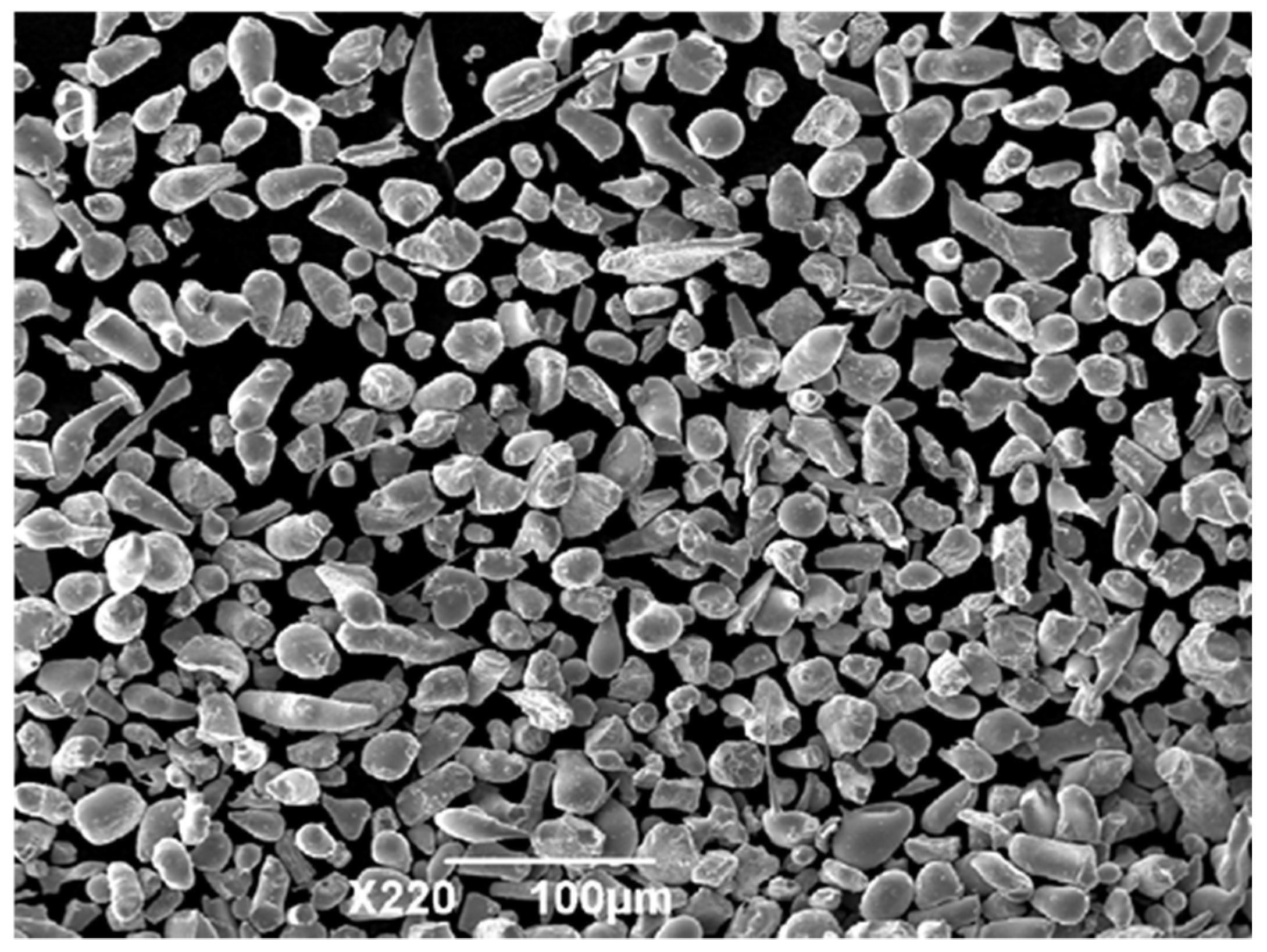
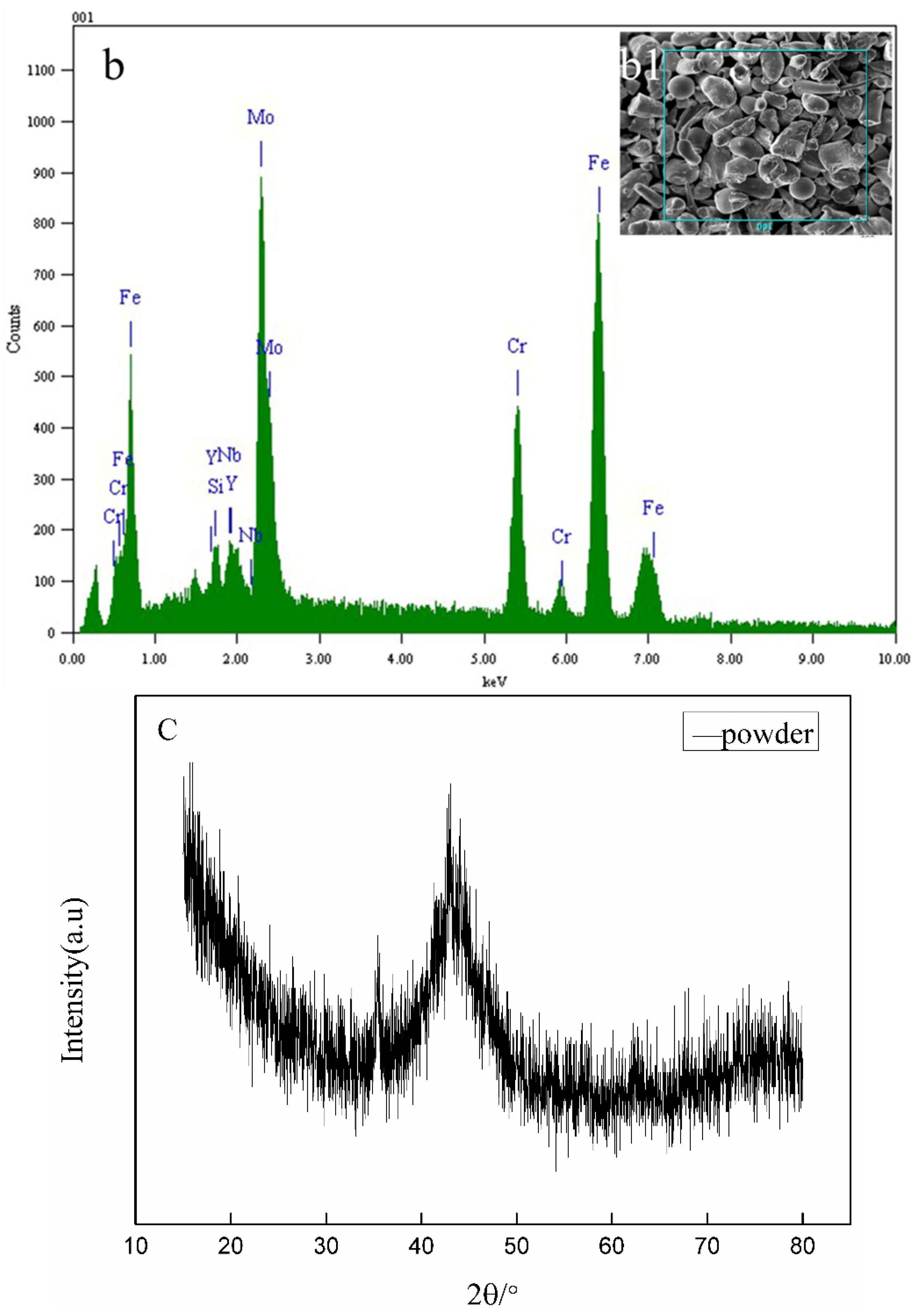
3.1. Powder Characteristics

In this experiment, the Fe-based powder selected is the gas-atomized amorphous powder. Figure 1 shows the micro-morphology of powder. The surface of the powder particles is relatively smooth, which ensures favorable fluidity for thermal spray processing. The powder particles size was observed by SEM. The result showed that the equal sizes of the powder particles were 10.0–50.0 μm (Figure 1a). EDS reveals the primary element distributions of the powders as shown in Figure 1b and Table 2. It is obvious that the proportion of Fe in powder is the highest; in addition, the proportion of Mo and Cr is 20% and 19%, respectively. Figure 1c shows the XRD patterns of the powders. Except for a broad amorphous diffraction peak at 44°, there are no peaks of crystalline phases. The broad amorphous diffraction peak illustrates high amorphous phase content of the powders.

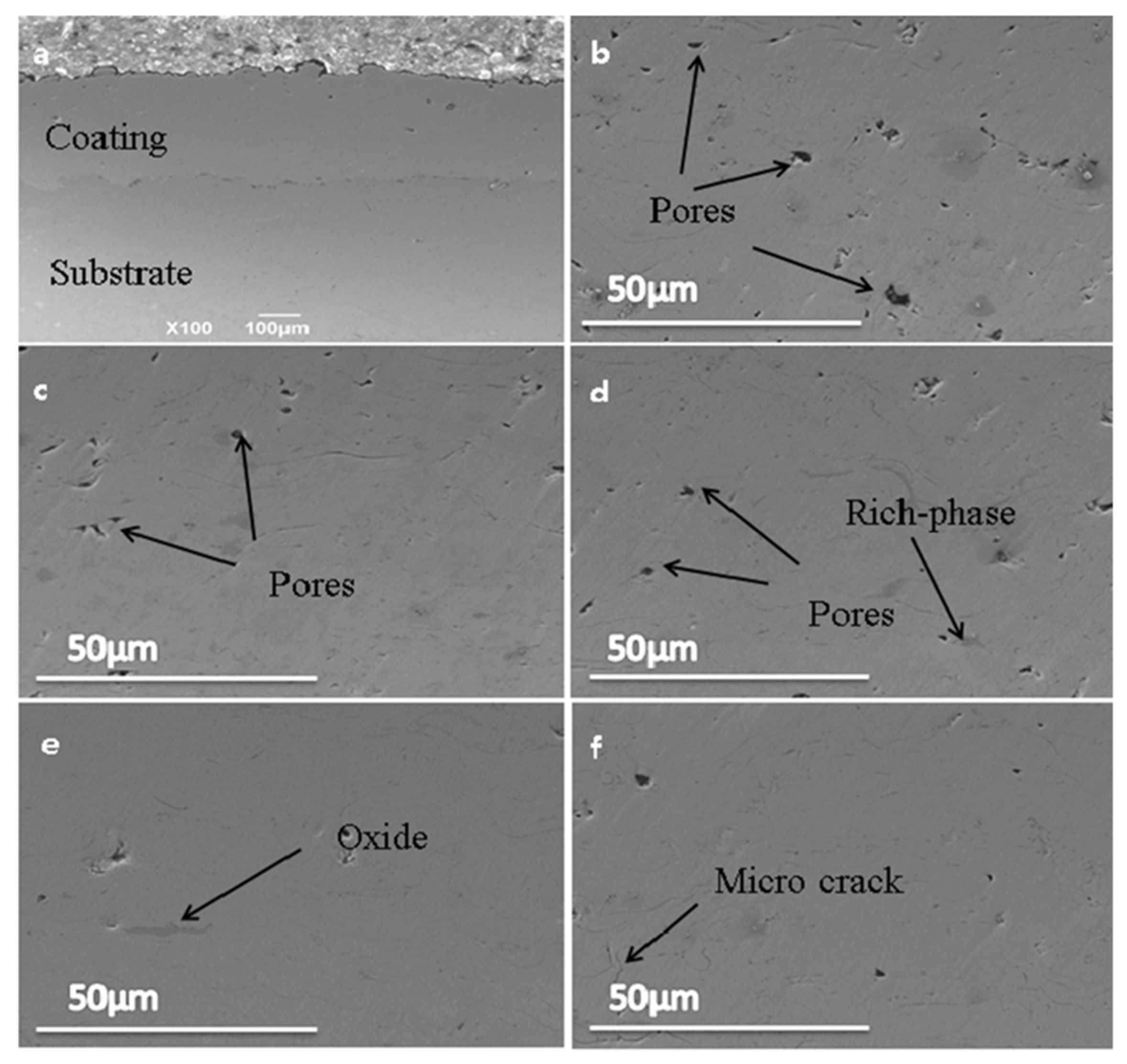
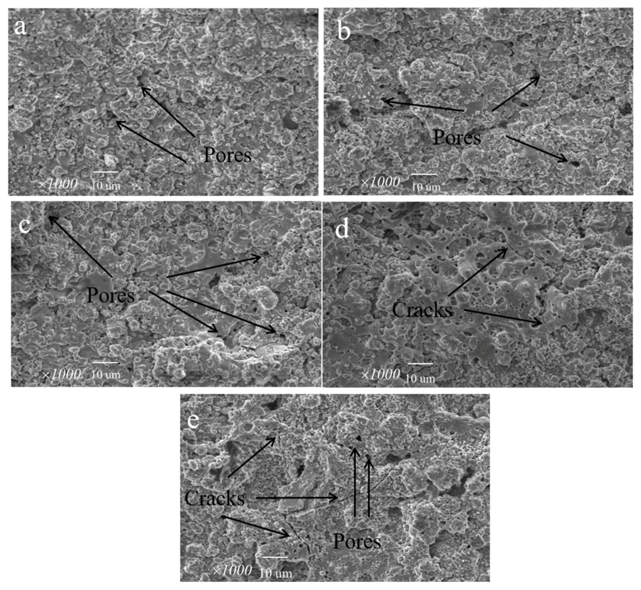
3.2. The Microstructure of the As-Sprayed Coating and Annealed Coatings

Figure 2 displays the typical microstructure of a cross-section of the as-sprayed coating and annealed coatings. As seen from the SEM images, all of the coatings have a dense lamellar structure with some finite pores. The reasons that the as-sprayed coatings contain finite pores are mainly associated with spraying process. In the spraying process, the high speed influence of semi-fused particles on the coatings accompanies rapid concretion. During the rapid cooling process, the surface of semi-molten particle shrinks, resulting in the appearance of some finite pores. And the junction of particles can also produce micropores due to rapid cooling. Nevertheless, it is clear that the pores decreased with increasing annealing temperature, this is because the un-melted particles undergo diffusion under the action of sintering.
In addition, cracks can be seen from the cross-sections of the annealed coatings; after heat treatment, nanocrystalline grains can be confirmed in the annealed coatings, and much more nanocrystalline grains exist in the annealed coatings can form crystal defects, which usually may generate the cracks [24]. It is obvious in from Figure 2 that the Fe-based amorphous/ nanocrystalline coatings have an inhomogeneous structure with black and gray zones. The EDS proved that the black area was an Fe rich area with a small quantity of Cr and Mo. In addition, the Fe-rich phase became blurry with the increase of annealing temperature. Many researchers also proved the inhomogeneous gray area containing iron oxide phase, and the content of the oxide phase increased with annealing temperature increasing [17,25,26,27]. The variation of microstructure indicated that sintering, diffusion and oxidation occurred during heat treatment.

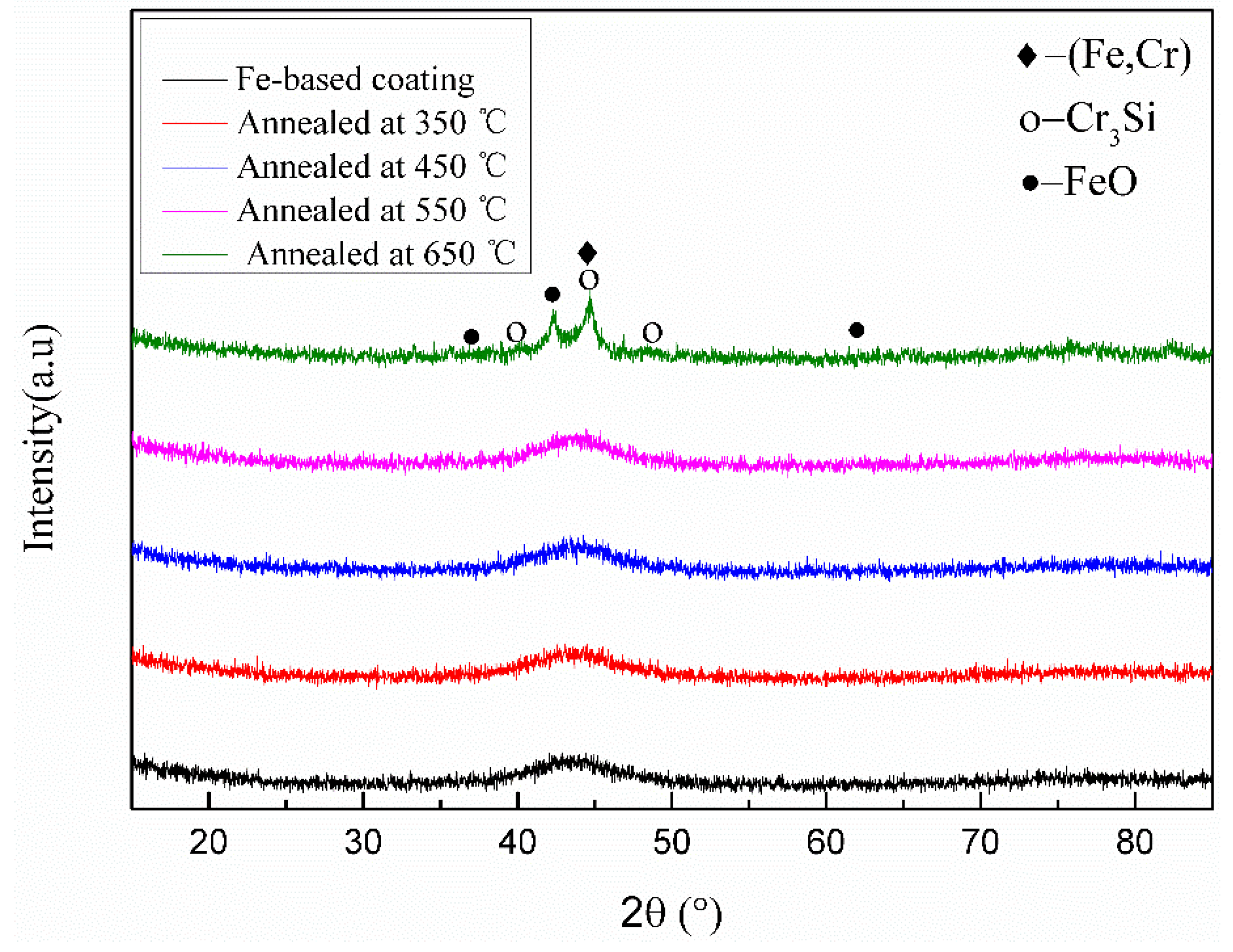
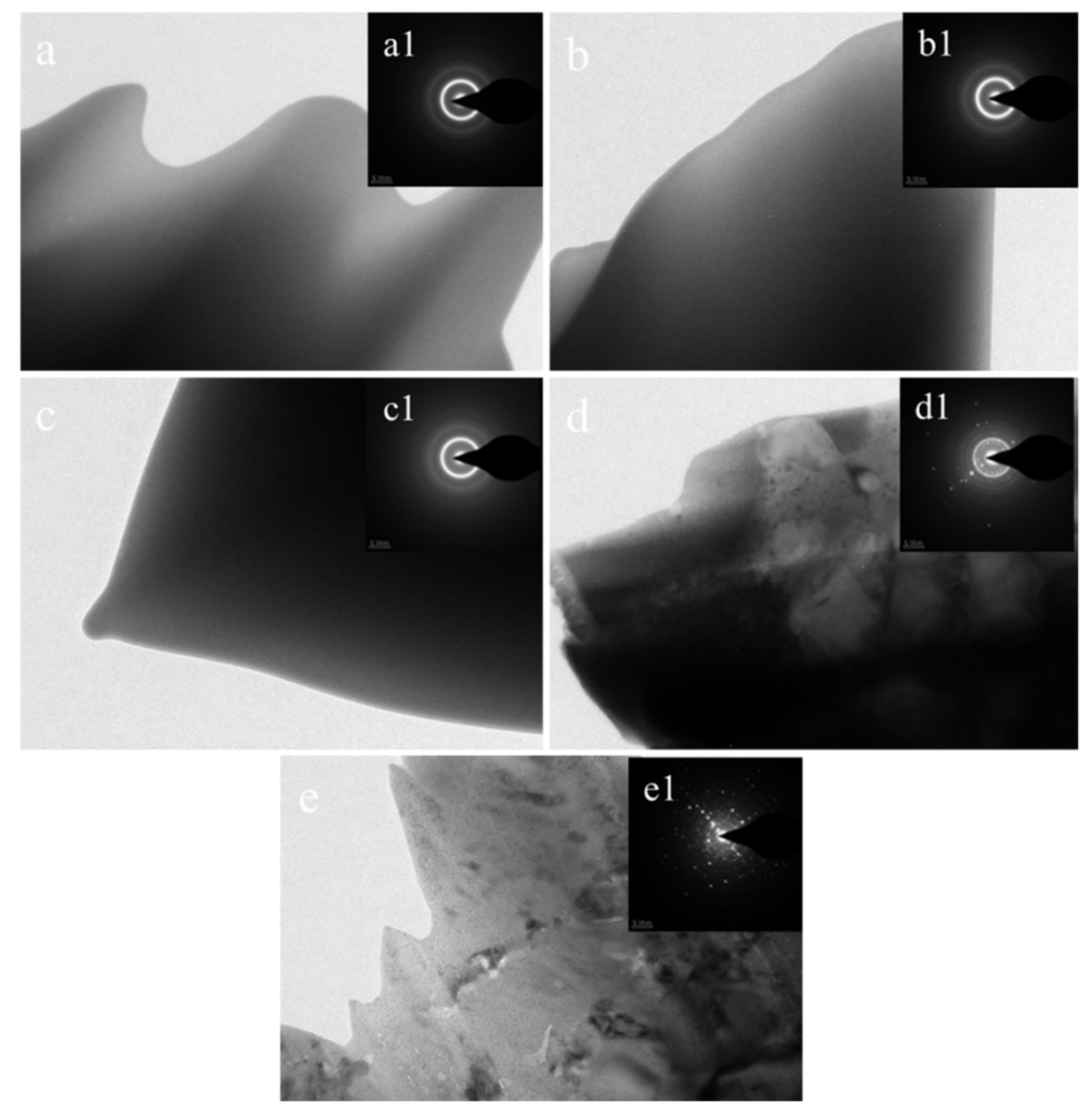
3.3. XRD and TEM Analysis

Figure 3 shows the XRD patterns of the coatings before and after annealing at 350, 450, 550 and 650 °C for 1 h, respectively. It is clear that the amorphous structures of the coatings did not change much after annealed at 350, 450 and 550 °C. All diffraction peaks of the coatings are low and broad, and it implies that high amorphous phase content in the coatings. After being annealed at 650 °C for 1 h, a crystallization phase appeared, and the broad amorphous diffraction peak disappeared in the coating. After heat treatment at 650 °C, the (Fe, Cr), Cr3Si and FeO phases were identified.
In order to further study the microstructure of the as-sprayed coating and annealed coatings in detail, a TEM analysis of the coatings was implemented. Figure 4a is a bright field TEM pattern of the as-sprayed coating, where the selected area electron diffraction (SAED) pattern has a wide diffraction ring. It shows that the amorphous phase is the main one in the as-sprayed coating. After annealing at 350 °C, in Figure 4b, the SAED of the coatings is a wide diffraction ring which is almost identical to the as-sprayed coating. The amorphous microstructure of the coating has not changed significantly. Figure 4c shows the SAED pattern of the coating after being annealed at 450 °C, which still holds a diffraction halo ring. This indicated that the amorphous coating has excellent thermal stability. After being annealed at 550 °C for 1 h, the phase composition slightly changes, the amorphous phase is no longer the sole phase in the coating, and some fine nanocrystalline were identified. After annealing, crystalline spots at 550 °C can be proved from the SAED pattern of bright field the TEM image in Figure 4d, which shows the diffraction ring of the amorphous phase around some sporadic diffraction spots. This showed that the annealing temperature was crystallization temperature and crystallization had appeared. The TEM micrograph and SAED images of the coating annealed at 650 °C for 1h reveal two disparate morphologies. The amorphous phase still exists, but quite a few crystalline spots were found, which confirmed that the coating annealed at 650 °C underwent the precipitation of crystalline phases.
There are some reasons why the amorphous transition temperature occurs at 650 °C. Firstly, in the spraying process, an intermittent spraying method is adopted to ensure that the coating surface is not in a high temperature state for a long time, so that the coating can be quickly cooled and the occurrence of crystallization is inhibited. Secondly, compared with HVOF technology, SPS technology has a higher heat source, which enables the powder to be fully melted and forms a flake structure when the liquid drops hit the substrate. Therefore, it can achieve a higher cooling rate during the solidification process of the droplet, which ensures a higher degree of amorphization [28]. Thirdly, adding molybdenum and chromium is a very effective way for depressing the fusing temperature and enhancing the amorphous forming ability of the Fe-based alloys [29,30]. In addition, the diffusion of atoms is controlled by the heat treatment temperature. At low temperatures, the diffusion of atoms is of a short-range and the amorphous phase does not change significantly. At 650 °C, atoms in the amorphous phase undergo long-range diffusion to form nanocrystalline structures.

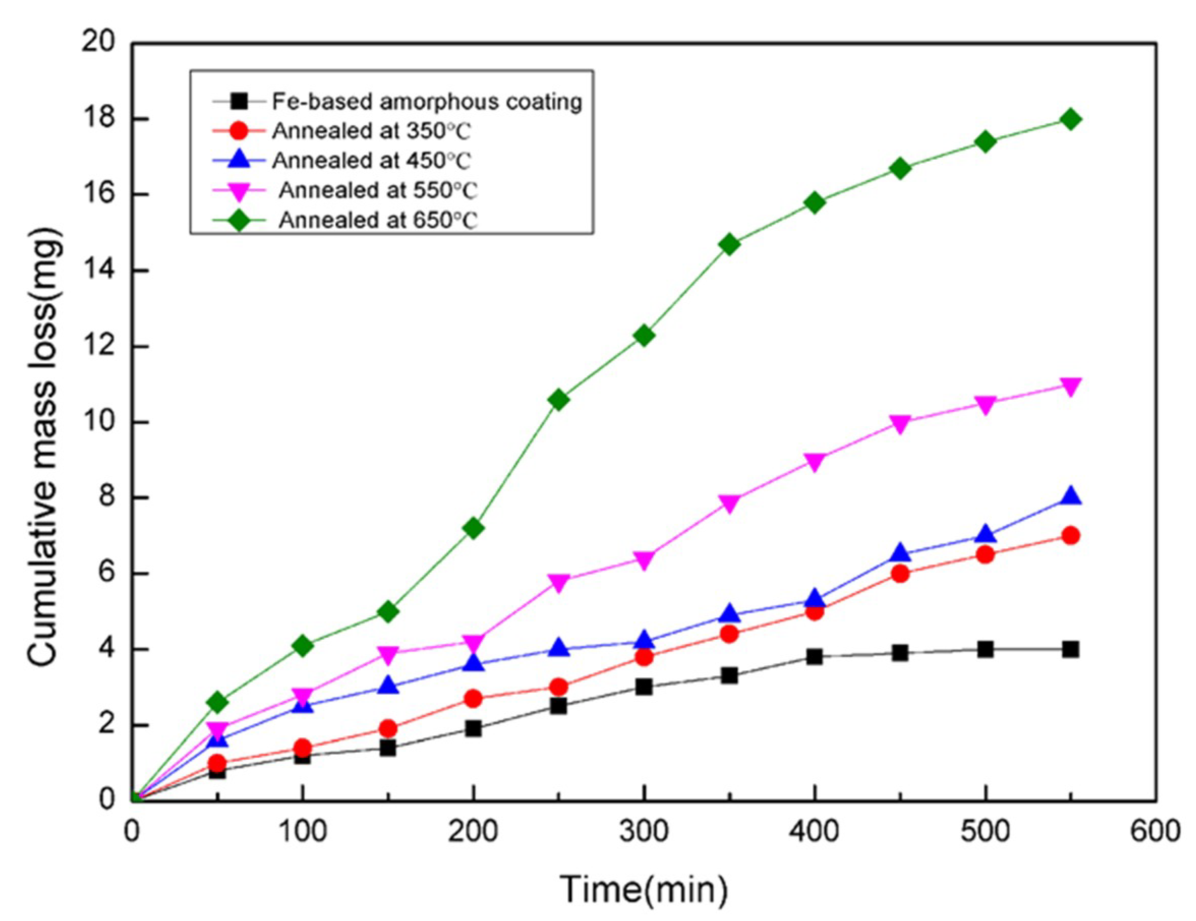
3.4. Influence of Annealing Temperature on the Corrosion Resistance

Figure 5 shows the polarization curves of the samples after open-circuit tests in a 3.5% NaCl solution. It can be seen that there are considerable differences in corrosion potential (Ecorr) and corrosion current densities (Icorr) between different samples (from Table 3). The as-sprayed coating shows lower Icorr and higher Ecorr than other annealed samples. The Ecorr of the coatings decreased with increasing annealing temperature, but the Icorr of the coatings increased.
There are three reasons for these phenomena. Firstly, although the quantity of pores decreased with the increasing annealing temperature, more and more puny cracks are formed (this can be inferred from the Figure 2). Generally, cracks can help the corrosion medium enter into the coatings, which will lead to faster corrosion rate. The as-sprayed coating with less cracks offers a better barrier to impede the electrolyte attack on the basis material [31]. Secondly, the amorphous content of Fe-based amorphous coatings decreased after heat treatment. The presence of a nanocrystalline phase created grain boundaries, segregates and crystalline defects, which plays a critical role of corrosion initiation sites [32,33]. Thirdly, coatings annealed at different temperature accelerated the existence of loose structure oxides on the coatings’ surface and inside. Generally speaking, the oxides increased with increasing annealing temperature, the vast oxides can loosen the bonding force of the coatings [34], and the corrosion medium via oxide pore entering into coatings.
Figure 6 shows the microstructure on the surface of all coatings immersed in a 3.5% NaCl solution for 540 min. A small number of holes is observed at the as-sprayed coating surface after the as-sprayed coating is immersed in a 3.5% NaCl solution for 540 min in Figure 6a. Compared with the surface of the as-sprayed coating, the coating annealed at 650 °C shows distinct cracks (Figure 6e). The surface morphology of the coating gets worse with increasing annealing temperature. Analyzing the reasons, some important changes occur on the surface of the coating and inside during the heat treatment process, such as coating oxides, grain boundaries or crystalline defects. This series of changes easily delivers paths for a corrosion medium to enter into the coating. The channel effect increases with the increase of the annealing temperature.
In order to clearly understand the influence of heat treatment on corrosion resistance, the effect of heat treatment on the mass loss of the sample immersed in a 3.5% NaCl solution for 540 min was studied (Figure 7). The result shows that the rate of mass loss increases rapidly with the increasing of annealing temperature. The sample has the largest mass loss when the temperature reached 650 °C. The mass loss of as-sprayed coating is lower than other annealed coatings. The mass loss of the as-sprayed coating and the annealed coatings at different temperatures are 4, 7, 8, 11 and 18 mg, respectively. The mass loss of the coating annealed at 650 °C (18 mg) is 4.5 times that of the as-sprayed coating. The reason for this phenomenon is that the number of grain boundaries, segregates and crystal defect increased with increasing annealing temperature [22,30]. Consequently, the mass loss of samples increased with the increase of heat treatment temperature.
Compared with other research results [17,29], in this study, coatings fabricated by high Cr-content powder shows lower mass loss, lower corrosion rate and better corrosion resistance. This phenomenon can be explained by the following reasons. Firstly, the coating shows the best corrosion resistance in connection with the formation of the passive film and slight passivation zone. The Cr added into the thermal spraying powders, under the action of heat treatment produced more chromium oxides, and the chromium oxide increased with increasing annealing temperature. A plentiful passive film successfully reduces the corrosion rate. This account can be confirmed by other researches [10,23]. In addition, compared with HVOF technology, the SPS technology has a higher heat source temperature to make powders melt more sufficiently and then spread to form a tabular-lamellar structure when droplets strike on the substrate. This compact lamellar structure can effectively resist the entry of corrosive media. Thus, high Cr-content coatings in this study fabricated by SPS show lower mass loss in a 3.5% NaCl solution and better corrosion resistance than others.

3.5. Influence of Annealing Temperature on the Microhardness

Table 4 shows the microhardness data of the as-sprayed coating and annealed coatings. The as-sprayed coating exhibited the lowest microhardness of about 721 HV among all coatings, while the microhardness values of the coatings annealed at 350, 450 and 550 and 650 °C were 848, 889, 982 and 1018 HV, respectively. The reasons why the maximum value of hardness appeared in 650 °C is as follows. Firstly, after heat treatment, the amorphous phase is partially transformed into a nanocrystalline structure, which disperses in the coating and strengthens it [35]. Secondly, when the annealing temperature is 650 °C, the rich-Cr, Mo phases and the second phase of Cr3Si form in the coating; these products play the role of solid solution strengthening [36]. Thus, it can explain that the annealing temperature plays a significant role in improving the microhardness of the coatings. In Figure 8, we clearly show the relation of the microhardness and annealing temperature.

4. Conclusions

Fe-based amorphous/nanocrystalline coatings produced by the SPS technique have compact lamellar structures with few pores. The compact lamellar structure makes the coatings exhibit excellent corrosion resistance. The study of heat treatment shows that heat treatment can promote the formation of nanocrystalline and the second phases. The formation of the second phase in the coatings results in an increase of microhardness. In conclusion, the amorphous structures of the coatings did not change much after annealing at 350, 450 and 550 °C and the crystallization of the amorphous phase occurred close to 650 °C.

Author Contributions

Data curation, S.L. and Y.Z.; Methodology, S.L., Y.Z. and R.J., Supervision, X.L. and X.Y.; Writing—original draft, Y.Z.; Writing—review and editing, S.L. and X.Z.

Funding

The research was supported by the National Key Research and Development Program of China (Grant No. 2017YFB0702100).

Acknowledgments

The authors are grateful for the support of the School of Materials Science and Engineering, Chang’an University.

Conflicts of Interest

The authors declare no conflict of interest.

References

  1. Qin, Y.J.; Wu, Y.P.; Zhang, J.F.; Guo, W.M.; Hong, S.; Chen, L.Y. Long-term corrosion behavior of HVOF sprayed FeCrSiBMn amorphous/nanocrystalline coating, Tran. Nonferrous Met. Soc. China 2015, 25, 1144–1150. [Google Scholar] [CrossRef]
  2. Peng, Y.; Zhang, C.; Zhou, H.; Liu, L. On the bonding strength in thermally sprayed Fe-based amorphous coatings. Surf. Coat. Technol. 2013, 218, 17–22. [Google Scholar] [CrossRef]
  3. Wang, W.; Zhang, C.; Xu, P.; Yasir, M.; Liu, L. Enhancement of oxidation and wear resistance of Fe-based amorphous coatings by surface modification of feedstock powders. Mater. Des. 2015, 73, 35–41. [Google Scholar] [CrossRef]
  4. Kishitake, K.; Era, H.; Otsubo, F. Characterization of plasma sprayed Fe–17Cr–38Mo–4C amorphous coatings crystallizing at extremely high temperature. J. Therm. Spray Techn. 1996, 5, 283–288. [Google Scholar] [CrossRef]
  5. Otsubo, F.; Kishitake, K. Corrosion resistance of Fe–16%Cr–30%Mo–(C,B,P) amorphous coatings sprayed by HVOF and APS processes. Mater. Trans. 2005, 46, 80–83. [Google Scholar] [CrossRef] [Green Version]
  6. Cheng, J.; Liu, D.; Liang, X.; Chen, Y. Wear behaviors of arc-sprayed FeBSiNb amorphous coatings. Tribol. Let. 2015, 60, 1–7. [Google Scholar] [CrossRef]
  7. Cherigui, M.; Fenineche, N.E.; Coddet, C. Structural study of iron-based microstructured and nanostructured powders sprayed by HVOF thermal spraying. Surf. Coat. Technol. 2005, 192, 19–26. [Google Scholar] [CrossRef]
  8. Wu, Y.; Lin, P.; Xie, G.; Hu, J.; Cao, M. Formation of amorphous and nanocrystalline phasesin high velocity oxy-fuel thermally sprayed a Fe–Cr–Si–B–Mn alloy. Mater. Sci. Eng. A 2006, 430, 34–39. [Google Scholar] [CrossRef]
  9. Guo, Y.; Koga, G.Y.; Jorge, A.M., Jr.; Savoie, S.; Schulz, R.; Kiminami, C.S.; Bolfarini, C.; Botta, W.J. Microstructural investigation of Fe–Cr–Nb–B amorphous/nanocrystalline coating produced by HVOF. Mater. Des. 2016, 110, 608–615. [Google Scholar] [CrossRef]
  10. Botta, W.J.; Berger, J.E.; Kiminami, C.S.; Roche, V.; Nogueira, R.P.; Bolfarini, C. Corrosion resistance of Fe-based amorphous alloys. J. Alloys Compd. 2014, 586, s105–s110. [Google Scholar] [CrossRef]
  11. Zhou, Y.Y.; Ma, G.Z.; Wang, H.D.; Li, G.L.; Chen, S.Y.; Wang, H.J. Fabrication and characterization of supersonic plasma sprayed Fe-based amorphous metallic coatings. Mater. Des. 2016, 110, 332–339. [Google Scholar] [CrossRef]
  12. Yasir, M.; Zhang, C.; Wang, W.; Xu, P.; Liu, L. Wear behaviors of Fe-based amorphous composite coatings reinforced by Al2O3 particles in air and in NaCl solution. Mater. Des. 2015, 88, 207–213. [Google Scholar] [CrossRef]
  13. Yoon, S.H.; Kim, J.; Kim, B.D.; Lee, C. Tribological behavior of B4C reinforced Fe-base bulk metallic glass composite coating. Surf. Coat. Technol. 2010, 205, 1962–1968. [Google Scholar] [CrossRef]
  14. Terajima, T.; Takeuchi, F.; Nakata, K.; Adachi, S.; Nakashima, K.; Igarashi, T. Composite coating containing WC/12Co cermet and Fe-based metallic glass deposited by high-velocity oxygen fuel spraying. J. Alloy. Compd. 2010, 504, S288–S291. [Google Scholar] [CrossRef]
  15. Yugeswaran, S.; Kobayashi, A.; Suresh, K.; Subramanian, B. Characterization of gas tunnel type plasma sprayed TiN reinforced Fe-based metallic glass coatings. J. Alloy. Compd. 2013, 551, 168–175. [Google Scholar] [CrossRef]
  16. Do, J.; Jeon, C.; Kim, C.P.; Lee, B.J.; Lee, S.; Lee, E.S.; Yoon, T.S.; Shin, Y.S. Effects of (Cr,Fe)2B borides on hardness in powder-injection-molded product fabricated with Fe-based alloy powders. Mater. Sci. Eng. A 2012, 556, 366–372. [Google Scholar] [CrossRef]
  17. Lin, J.; Wang, Z.; Lin, P.; Cheng, J.; Zhang, X.; Hong, S. Effects of post annealing on the microstructure, mechanical properties and cavitation erosion behavior of arc-sprayed FeNiCrBSiNbW coatings. Mater. Des. 2015, 65, 1035–1040. [Google Scholar] [CrossRef]
  18. Lin, J.R.; Wang, Z.H.; Lin, P.H.; Cheng, J.B.; Zhang, X.; Hong, S. Effect of crystallization on electrochemical properties of arc sprayed FeNiCrBSiNbW coatings. Surf. Eng. 2014, 30, 683–687. [Google Scholar] [CrossRef]
  19. Goedjen, J.G.; Shores, D.A. The effect of alloy grain size on the transient oxidation behavior of an alumina-forming alloy. Oxid. Met. 1992, 37, 125–142. [Google Scholar] [CrossRef]
  20. Guo, W.; Wu, Y.; Zhang, J.; Yuan, W. Effect of the long-term heat treatmenton the cyclic oxidation behavior of Fe-based amorphous/nanocrystalline coatings prepared by high-velocity arc spray process. Surf. Coat. Technol. 2016, 307, 392–398. [Google Scholar] [CrossRef]
  21. Zhang, P.; Yan, H.; Xu, P.; Lu, Q.; Li, C.; Yu, Z. Influence of different annealing temperatures and cooling rates on amorphous and crystalline composite coating. Surf. Coat. Technol. 2012, 206, 4981–4987. [Google Scholar] [CrossRef]
  22. Li, D.; Chen, X.; Hui, X.; Wang, J.; Jin, P.; Li, H. Effect of amorphicity of HVOF sprayed Fe-based coatings on their corrosion performances and contacting osteoblast behavior. Surf. Coat. Technol. 2017, 310, 207–213. [Google Scholar] [CrossRef]
  23. Yang, Y.; Zhang, C.; Peng, Y.; Yu, Y.; Liu, L. Effects of crystallization on the corrosion resistance of Fe-based amorphous coatings. Corros. Sci. 2012, 59, 10–19. [Google Scholar] [CrossRef]
  24. Fu, B.Y.; He, D.Y.; Zhao, L.D. Effect of heat treatment on the microstructure and mechanical properties of Fe-based amorphous coatings. J. Alloy. Compd. 2009, 480, 422–427. [Google Scholar] [CrossRef]
  25. Thakur, L.; Arora, N. A study on erosive wear behavior of HVOF sprayed nanostructured WC–CoCr coatings. J. Mech. Sci. Technol. 2013, 27, 1461–1467. [Google Scholar] [CrossRef]
  26. Lin, J.R.; Wang, Z.H.; Lin, P.H.; Cheng, J.B.; Zhang, J.J.; Zhang, X. Microstructureand corrosion resistance of Fe-based coatings prepared by twin wires arc spraying process. J. Therm. Spray Technol. 2014, 23, 333–339. [Google Scholar] [CrossRef]
  27. Lee, C.H.; Min, K.O. Effects of heat treatment on the microstructure and properties of HVOF-sprayed Ni–Cr–W–Mo–B alloy coatings. Surf. Coat. Technol. 2000, 132, 49–57. [Google Scholar] [CrossRef] [Green Version]
  28. Zhou, Z.; Wang, L.; He, D.Y.; Wang, F.C.; Liu, Y.B. Microstructure and electrochemical behavior of Fe-based amorphous metallic coatings fabricated by atmospheric plasma spraying. J. Therm. Spray Technol. 2011, 20, 344–350. [Google Scholar] [CrossRef]
  29. Guo, R.Q.; Zhang, C.; Yang, Y.; Peng, Y.; Liu, L. Corrosion and wear resistance of a Fe-based amorphous coating in underground environment. Intermetallics 2012, 30, 94–99. [Google Scholar] [CrossRef]
  30. Liu, S.; Zheng, X.; Geng, G. Dry sliding wear behavior and corrosion resistance of NiCrBSi coating deposited by activated combustion-high velocity air fuel spray process. Mater. Des. 2010, 31, 913–917. [Google Scholar] [CrossRef]
  31. Jinran, L.; Zehua, W.; Jianguo, C.; Min, K.; Xiuqing, F.; Sheng, H. Evaluation of cavitation erosion resistance of are-sprayed Fe-based amorphous/nanocrystalline coatings in NaCl solution. Results Phys. 2019, 12, 597–602. [Google Scholar]
  32. Wang, Z.H.; Zhang, X.; Cheng, J.B.; Lin, J.R.; Zhou, Z.H. Cavitation erosion resistance of Fe-based amorphous/nanocrystal coatings prepared by high-velocity arc spraying. J. Therm. Spray Technol. 2014, 23, 742–749. [Google Scholar] [CrossRef]
  33. Bakare, M.S.; Voisey, K.T.; Chokethawai, K.; McCartney, D.G. Corrosion behavior of crystalline and amorphous forms of the glass forming alloy Fe43Cr16Mo16C15B10. J. Alloy. Compd. 2012, 527, 210–218. [Google Scholar] [CrossRef] [Green Version]
  34. Kim, J.H.; Lee, M.H. A study on cavitation erosion and corrosion behavior of Al-, Zn-, Cu-, and Fe-based coatings prepared by arc spraying. J. Therm. Spray Technol. 2010, 19, 1224–1230. [Google Scholar] [CrossRef]
  35. Chokethawai, K.; McCartney, D.G.; Shipway, P.H. Microstructure evolution and thermal stability of an Fe-based amorphous alloy powder and thermally sprayed coatings. J. Alloy. Compd. 2009, 480, 351–359. [Google Scholar] [CrossRef]
  36. Parthasarathi, N.L.; Duraiselvam, M.; Borah, U. Effect of plasma spraying parameter on wear resistance of NiCrBSiCFe plasma coatings on austenitic stainless steel stainless steel ay elevated temperatures at various loads. Mater. Des. 2012, 36, 141–151. [Google Scholar] [CrossRef]
Figure 1. Microstructure of the powder. (a) SEM picture of the powder; (b) EDS analysis of the powder; (b1) EDS selection region; (c) XRD pattern of the powder.
Coatings 09 00858 g001aCoatings 09 00858 g001b
Figure 2. The microstructure of the Fe-based amorphous coating and annealed coatings. (a) the Fe-based amorphous coating; (b) as-sprayed coating; (c) annealed at 350 °C; (d) annealed at 450 °C; (e) annealed at 550 °C; (f) annealed at 650 °C.
Coatings 09 00858 g002
Figure 3. The XRD patterns of the as-sprayed coating and annealed coatings.
Coatings 09 00858 g003
Figure 4. The TEM pictures of the as-sprayed coating and annealed coatings. (a) as-sprayed coating; (a1) as-sprayed coating SAED; (b) annealed at 350 °C; (b1) annealed at 350 °C SAED; (c) annealed at 450 °C; (c1) annealed at 450 °C SAED; (d) annealed at 550 °C; (d1) annealed at 450 °C SAED; (e) annealed at 650 °C; (e1) annealed at 450 °C SAED.
Coatings 09 00858 g004
Figure 5. The potentiodynamic polarization curves of the coatings.
Coatings 09 00858 g005
Figure 6. The microstructure of the Fe-based amorphous coating and annealed coatings after immersion in 3.5% NaCl solution for 540 min. (a) as-sprayed coating; (b) annealed at 350 °C; (c) annealed at 450 °C; (d) annealed at 550 °C; (e) annealed at 650 °C.
Coatings 09 00858 g006
Figure 7. The effect of annealing temperature on the mass loss.
Coatings 09 00858 g007
Figure 8. The effect of annealing temperature on the microhardness.
Coatings 09 00858 g008
Table 1. Major spraying parameters.
Spray ParametersValues
Power (kW)41.4
Argon flow (L/min)80
Hydrogen flow (L/min)6
Powder flow rate (g/min)40
Standoff spray distance (mm)110
Coating thickness (μm)350 ± 25
Table 2. Chemical composition of powder (wt.%).
FeMoCrYSiNb
57.142220.450019.03782.16170.73910.4692
Table 3. The Corrosion potential and corrosion current densities of the coatings.
CoatingsEcorr (V)Icorr (A)
As-sprayed−0.345212.2626 × 10−5
Annealed at 350 °C−0.439648.695 × 10−5
Annealed at 450 °C−0.454352.5059 × 10−4
Annealed at 550 °C−0.466173.1165 × 10−4
Annealed at 650 °C−0.524953.1392 × 10−4
Table 4. The microhardness of the as-sprayed coating and annealed coatings.
CoatingsAs-Sprayed CoatingAnnealed at 350 °CAnnealed at 450 °CAnnealed at 550 °CAnnealed at 650 °C
Microhardness/HV7128488899821018

