Article

On Friction Reduction by Surface Modifications in the TEHL Cam/Tappet-Contact-Experimental and Numerical Studies

Engineering Design, Friedrich-Alexander-Universität Erlangen-Nürnberg, Martensstr. 9, 91058 Erlangen, Germany
*
Author to whom correspondence should be addressed.
Coatings 2019, 9(12), 843; https://doi.org/10.3390/coatings9120843
Submission received: 14 November 2019 / Revised: 4 December 2019 / Accepted: 6 December 2019 / Published: 9 December 2019
(This article belongs to the Special Issue Tribological Behavior of Functional Surface: Models and Methods)

Abstract

:
The overall energy efficiency of machine elements and engine components could be improved by using new technologies such as surface modifications. In the literature, surface engineering approaches like micro-texturing and the application of diamond-like carbon (DLC) coatings were frequently studied separately, with focus on a specific model contact and lubrication conditions. The contribution of the current study is to elucidate and compare the underlying friction reduction mechanisms of the aforementioned surface modifications in an application-orientated manner. The study applied the operating conditions of the thermo-elastohydrodynamically lubricated (TEHL) cam/tappet-contact of the valve train. Therefore, tribological cam/bucket tappet component Stribeck tests were used to determine the friction behavior of ultrashort pulse laser fabricated microtextures and PVD/PECVD deposited silicon-doped amorphous carbon coatings. Moreover, advanced surface characterization methods, as well as numerical TEHL tribo-simulations, were utilized to explore the mechanisms responsible for the observed tribological effects. The results showed that the DLC-coating could reduce the solid and fluid friction force in a wide range of lubrication regimes. Conversely, micro-texturing may reduce solid friction while increasing the fraction of fluid friction.

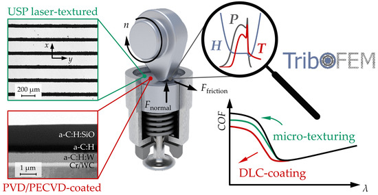
Graphical Abstract

1. Introduction

Approximately one-fifth of the fuel energy in passenger cars is used to overcome friction in engines, of which about 15% is consumed in the valve train (Holmberg et al. [1]). According to many experts, for example, Kalghatgi [2] and Serrano et al. [3], internal combustion engines (ICE) will not diminish in relevance worldwide even in times of increasing powertrain electrification. In addition, the obtained insights can also be transferred to other tribological rolling-sliding-contacts, for example, in the newly emerging field of electric vehicles (Farfan-Cabrera [4]). The total energy efficiency could be significantly increased by utilizing new technologies such as surface modifications (Holmberg and Erdemir [5]). This can be achieved, for instance, by applying amorphous carbon (DLC) coatings (Kalin et al. [6], Erdemir and Donnet [7]) or discrete microtextures (Gropper et al. [8], Gachot et al. [9,10,11]) onto the rubbing surfaces of lubricated tribological sliding contacts. Both approaches have been intensively investigated in the literature within various theoretical and experimental studies ranging from boundary (Pettersson and Jacobson [12]), to mixed (Löffler et al. [13], Borghi et al. [14]), as well as full-film hydrodynamic (Etsion [15], Pawlus et al. [16,17]) and elastohydrodynamic lubrication. With advancing experimental and numerical methods, the effects of surface modifications particularly in non-conformal thermo-elastohydrodynamically lubricated (TEHL) contacts, have been the subject of numerous investigations.
Evans et al. [18] and Kalin et al. [19,20] identified the wall slip between dispersive lubricants and highly dispersive coated surfaces as being responsible for friction reductions of up to 20% using tetrahedral amorphous carbon (ta-C), hydrogenated amorphous carbon (a-C:H), and doped DLC (a-C:H:Si, a-C:H:N, a-C:H:F) coatings compared to uncoated references in ball-on-flat experiments. Björling et al. [21] investigated the frictional behavior of a-C:H coatings in a ball-on-disk tribometer, where friction decreased with increasing coating thickness, wherein a reduction of up to 41% was observed. From contact angles, surface energies, and spreading parameters, the authors concluded that the friction reduction was not only due to solid–liquid interactions but also due to a thermal insulation effect. The outcome was further observed by Björling et al. [22,23] using a combined experimental and numerical approach. In ball-on-disk tests, the authors observed a friction reduction of up to 16% if one contacting body was coated, and up to 25 % if both bodies were coated (a-C:H). Thermo-elastohydrodynamically lubricated (TEHL) simulation results indicated the highest contact temperatures when both bodies were coated, and the lowest temperatures for the uncoated reference case, which was attributed to the lower thermal inertia of the amorphous carbon coatings. Bobzin et al. [24] also attributed a friction reduction of up to 45% from a-C:H:ZrC and a-C:H:nc-ZrC coatings, observed in twin-disk tests to higher flash temperatures due to thermal insulation effects. The effects led to the lower shear resistance of the lubricant and lower mass temperatures of the disk, which resulted in a higher lubricant gap. Elsharkawy et al. [25] numerically studied the influence of mechanical coating properties and their thickness on the EHL pressure and fluid film thickness distribution. The authors found that coatings with a lower elastic modulus led to wider contact areas and lower maximum pressures. The influence of the mechanical coating properties increased with the coating thickness. Based on the finite element simulation approach, Habchi et al. [26] investigated the influence of both the thermal and mechanical effects of coatings on the TEHL contact. The results were in good agreement with the investigations mentioned above. Coatings with high thermal inertia showed temperature and friction coefficients that were similar to uncoated references, whereas low thermal inertia coatings featured a friction reduction of up to 50%. The result was enhanced by higher coating thickness and sliding speed. Using twin-disk tests and accompanying TEHL simulations with a 50% slip and a-C:H-coated specimens, Bobach et al. [27] showed a friction reduction of up to 40% compared to the uncoated references. Therefore, higher contact temperatures, as well as lower bulk temperatures, were observed due to the lower heat conductivity of the amorphous carbon coating, resulting in the observed fluid friction reduction. However, the authors noted that for pronounced mixed friction, the boundary friction between the surfaces could not be ignored. By comparing thin-film sensor measurements in a twin-disk test-rig using TEHL simulations, Ebner et al. [28] demonstrated higher contact temperatures due to ZrO2 and Al2O3-coatings compared to the uncoated specimens.
Regarding texturing, various early investigations, e.g., by Choo et al. [29,30], Ehret et al. [31], and Venner and Lubrecht [32], on surfaces with regular features using optical interferometry or numerical simulations indicated the direct involvement of surface topography on elastohydrodynamic lubrication. Therefore, grooves and ridges orientated transversely to the direction of sliding tended to enhance the mean fluid film thickness, whereas longitudinal surface features instead induced adverse effects. Initial experimental and numerical studies on discrete surface features were carried out by Cusano and Wedeven [33] and Ai and Cheng [34], respectively. Using optical interferometry in an EHL tribometer under 50% slip conditions and accompanying numerical simulations, Mourier et al. [35] showed that deep cavities reduced the lubricant gap while shallow dimples fabricated by laser texturing enlarged the fluid film. The effect was related to the highly viscous lubricant that was drawn out of the texture due to shear effects and an additional elastic deformation. Complementary studies (Mourier et al. [36]) indicated the optimal depths and diameters of the dimples for lubricant gap enlargement below or above, wherein less positive or even detrimental effects occurred. The role of shallow textures, velocity differences, and high lubricant viscosity was further emphasized by Krupka and Hartl [37].
Moreover, Krupka et al. [38] studied shallow dimples under mixed EHL conditions using thin film colorimetric interferometry. They found that lubricant expelled from microtextures could effectively lift off real roughness features, providing an increase in the average film thicknesses. Investigations using a twin-disk test-rig by Bobzin et al. [24] showed a friction reduction induced by deterministic laser textures but only at higher contact stresses, low velocities, and high slips. Rosenkranz et al. [39] mapped the conditions under mixed and full film EHL from which friction reduction could be obtained using hot micro-coined samples in the ball-on-disk tests. Thus, shallow textures and lower area coverage between 10 and 20% resulted in pronounced friction reductions of up to a factor of 3 at low sliding velocities. Marian et al. [40] combined ball-on-disk experiments with EHL simulations, taking mixed lubrication into account, to study the influence of the structural parameters of single hemispherical microtextures on the resulting lubrication conditions, friction, and wear. The authors used meta-modeling and biological evolution-inspired optimization algorithms to derive beneficial and robust micro-texture designs. Textures with a shallow depth and a diameter close to the elastically deformed contact area were found to be favorable, with a friction reduction up to 60% due to an additional hydrodynamic pressure build-up, a local lubricant gap enlargement, as well as reduced asperity contact.
The studies above were limited to coating or microtexturing in model contacts or under constant lubrication conditions. Meanwhile, dynamic and different lubrication conditions are present in real applications. Since both surface modification approaches are particularly suitable for machine elements with high amounts of sliding, several investigations have dealt with gear wheel pairings. Bobzin et al. [24] studied the influence of a-C:H:ZrC and a-C:H:nc-ZrC coated and laser-textured spur gears using a gear efficiency test-rig. For the microtextured tooth flanks, a desirable friction behavior with an improvement of up to 7% compared to the polished references was observed under extreme mixed friction conditions. A significant friction reduction of up 39% was observed for the amorphous carbon-coated gear wheels. Although a reduction in frictional losses was observed at lower circumferential speeds, this reduction was more pronounced at higher gear wheel speeds. Again, this was attributed to the low thermal inertia of the amorphous carbon coatings. Beilicke et al. [41] performed transient TEHL simulations of an amorphous carbon-coated helical gear pair, taking mixed lubrication into account. The observed reduced friction up to 27% was explained by the thermal insulation of the coating, resulting in lower effective lubricant viscosity. Coating both the pinion and wheel resulted in higher temperatures, lower traction coefficients, and lower minimum lubricant gap compared to the single-sided coated gear pair. For the latter, the fluid temperature was shifted towards the coated surface. Using TEHL simulations of spur gears, Ziegltrum et al. [42] showed a similar trend in frictional behavior for different lubricants (mineral, polyalphaolefin, and polyglycol oil) due to the thermal insulation effects of the amorphous carbon coating. However, the degree of friction reduction varied between 14% and 28%, depending on the lubricant properties.
The TEHL cam/tappet-contact of the valve train represents another engine component with high frictional losses and a high amount of sliding. Kano et al. [43] reported that hydrogen-free amorphous carbon coatings (ta-C), while using additized (GMN) PAO base oïl, led to super-low friction coefficients (below 0.01) in a single cam and follower test-rig, as well as friction reductions up to 45% in motor-driven valve train tests. Dobrenizki et al. [44] studied the influence of engine oil, additives, temperature, and camshaft speed on efficiency improvement from a-C:H:ZrC and a-C:H:X coatings on single automobile bucket tappets in contact with a cam. Yu et al. [45] numerically investigated the effects of mechanical and thermal coating properties on the TEHL cam/tappet-contact under full-film conditions. They found that frictional losses were significantly affected by thermal effects and that soft coatings with low thermal inertia were most favorable. Coating both the tappet and cam resulted in higher TEHL temperatures and lower friction coefficients.
Furthermore, using transient full-film TEHL simulations, Meng et al. [46] concluded that amorphous carbon coating induced thermal insulation effects that are particularly beneficial in start-up processes of the cam/tappet-contact, leading to significantly reduced frictional losses. Gangopadhyay and Watt [47] used a motored valve train test-rig to determine a friction reduction of up to 35% from shallow V-shaped grooves fabricated by a diamond cutting tool. Krupka et al. [48] studied the effect of an array of micro-dimples on lubrication conditions using optical interferometry in a ball-on-disk machine, mimicking the transient operating conditions of the cam/tappet-contact. They showed that lubricant drawn out from the micro-pockets helped to separate the rubbing surfaces especially under thin-film conditions where the counter-bodies featured opposing sliding speeds. Employing a component test-rig, Marian et al. [49] studied the tribological performance of shallow line-shaped microtextures applied on tappets in the cam-contact operating under mixed lubrication conditions. For pure mineral oil, a significant friction reduction of up to 14 % was determined, which correlated well with measurements from an electrical resistivity circuit. The results and accompanying EHL simulations indicated that reduced asperity contact was responsible for the outcome. From the same test-rig, Tremmel et al. [50] determined a strong dependency on the frictional behavior of microtextured tappets on the lubricant viscosity, with higher viscosities being favored. Based on TEHL simulations and subsequent meta-modeling and optimization, the same authors concluded that shallow line-shaped textures arranged perpendicular to the direction of motion and with a width close to the elastically deformed contact area were most beneficial.
In summary, amorphous carbon coating and surface micro-texturing offer great potential to improve the energy efficiency in EHL contacts with a high amount of sliding, operating under a mixed or full-film regime. However, many studies have only focused on model contacts and constant lubrication conditions. Moreover, despite the very similar basic idea of amorphous carbon coating and micro-texturing, i.e., to improve the energy efficiency of a tribological contact without influencing other components, e.g., through design changes, the two approaches were usually considered separately. For these reasons, this paper aims to elucidate and compare the underlying friction reduction mechanisms under application-orientated operating conditions in the cam/tappet-contact of the valve train. Therefore, component tests with amorphous carbon-coated and microtextured bucket tappets were carried out and supplemented by surface characterization, as well as numerical TEHL tribo-simulations, which offered the potential to explore the underlying mechanisms. The results of this study were partly presented orally at the 74th STLE Annual Meeting and Exhibition 2019 in Nashville, Tennessee [51].

2. Materials and Methods

2.1. Experimental Methods

2.1.1. Materials

For testing, mechanical bucket tappets with top adjusting shims made of 16MnCr5 (1.7131, AISI 5115), with a diameter of 28 mm and height of 2.5 mm, were used and either microtextured or coated with amorphous carbon. The specimens were case-hardened to 62 + 2 HRC, mirror-polished to Ra ≈ 0.005 μm, and ultrasonically cleaned in acetone and isopropyl alcohol.

2.1.2. Microtexturing

Texturing of the specimen surfaces, as depicted in Figure 1a, was carried out using an ultrashort pulse (USP) laser ablation process (Fuego, Time Bandwidth, Zurich, Swiss) and a 2D scanner system (Scanlab, Puchheim, Germany) with a scanning speed of 600 mm/s. Nd:YVO4 generated a beam with 1064 nm wavelength and an averaged power of 802 mW. The pulse rate of 200 kHz and the short pulse duration of 10 ps allowed a precise process with low ablation per pulse, a small heat-affected zone, and the high quality of fabricated microtextures. The beam was focused to a minimum spot diameter of 37 μm using an F-theta lens with a focal length of 160 mm. After texturing, the specimens were polished again to remove manufacturing induced material accumulation at the texture edges and to adjust the final roughness (Ra ≈ 0.005 μm) and texture depth. Thus, we set a shallow depth of around 2 μm. Lateral dimensions of each texture element were constant at 35 μm in, as well as 2 mm perpendicular to the direction of motion. Distances between the textures were 180 μm in and 1 mm perpendicular, respectively. This measure corresponded to area coverage of approximately 10%. The values were chosen as they were advantageous as described in the literature and previous studies [49,50].

2.1.3. Coating

Among the group of DLC-coatings, a silicon-doped hydrogenated amorphous carbon coating (a-C:H:SiO), as illustrated in Figure 1b, was deposited using an industrial scale PVD/PECVD coating machine (TT 300, H-O-T, Nuremberg, Germany) with a two-fold rotating charging rack. Before deposition, the specimens were argon ion plasma-etched inside the deposition chamber, applying an argon flow of 500 sccm and a −500 V pulsed DC bias voltage at 300 °C for 40 min. Since carbon-based layers usually show poor adhesion when directly deposited on steel substrates, we applied a thin adhesion layer of chromium (Cr) and an interlayer of tungsten carbide (WC). Furthermore, interlayers of tungsten-doped hydrogenated amorphous carbon (a-C:H:W) and pure hydrogenated amorphous carbon (a-C:H) contributed to a gradual increase in hardness from the substrate towards the top layer and improved the coating’s load-carrying capacity. Finally, a top layer of a-C:H:SiO served as a tribologically effective functional layer. Interfaces to the substrate and between layers were graded by continuous adjustment of the process parameters. The Cr adhesion layer and the WC interlayer were prepared by the steered arc evaporation of a Cr-target and unbalanced magnetron (UBM) sputtering of a binder-free WC-target, respectively. PECVD processes were employed to deposit a-C:H and a-C:H:SiO layers by evaporating HDMSO and applying argon and acetylene as process and reactive gas. The a-C:H:W layer was generated in a reactive PVD process by sputtering the WC-target under an argon-acetylene atmosphere. The WC-target was used with bipolar pulsed DC voltages applying set target voltages as the negative pulse amplitudes. The levels of the positive pulses represented 15% of the adjusted target voltages. During the deposition of the WC interlayer, the pulse frequency was kept constant at 40 kHz with the duration of a positive pulse of 5 µs. Preparing the a-C:H:W layer, the pulse parameters were set to 70 kHz and 4 µs, respectively, to prevent the WC-target from poisoning. The PECVD processes required bipolar (15% positive pulse voltage level) and unipolar pulsed bias voltages (pulse frequency of 40 kHz, positive pulse duration of 5 µs). Relevant deposition parameters for each coating layer are listed in Table 1. After deposition, the coated samples were polished to Ra ≈ 0.047 μm.

2.1.4. Characterization and Tribological Testing

The indentation hardness HIT and indentation modulus EIT were measured by nanoindentation using a Picodenter HM500 (HELMUT FISCHER, Sindelfingen, Germany). The HIT and EIT values of the coating were determined at a maximum load of 3 mN, ensuring indentation depths of the Vickers indenter of less than 10% of the coating thickness to minimize the influence of the substrate material [52]. A load of 500 mN was chosen for the indentation of the uncoated steel substrate. To compensate for the statistical scattering due to surface roughness and irregularities, we performed twenty indentations of which not more than four significant outliers were precluded from the evaluation.
The specimens were further characterized by laser scanning microscopy (LSM, VK-X200, Keyence, Neu-Isenburg, Germany) and focused ion beam preparation (FIB, Scientific Helios NanoLab 600i, Thermo Fisher, Waltham, Massachusetts, United States) to illustrate the textured surface and the coating architecture, as shown in Figure 1b,c.
Tribological testing was carried out on a single cam/single bucket tappet component test-rig (TSRP, KTmfk, Erlangen, Germany), as described by Dobrenizki et al. [44], Marian et al. [49], and Tremmel et al. [50]. This testing is illustrated in Figure 1c, utilizing standard valve train parts (cam, spring, valve) to ensure realistic conditions. The shims were fixed in the recess of a tappet adapter using a temperature and impact resistant adhesive (Loctite 480, HENKEL, Düsseldorf, Germany). A pin restricted the rotation of the tappets within their guidance during testing to maintain the same orientation of the line-shaped textures to the contact area. The 100Cr6 (1.3505, AISI 52100) cam (Ra ≈ 0.2 μm) without profiling, at a width of 10 mm, a base radius of 15 mm, and a tip radius of 2.3 mm was cut out of a series camshaft, provided with cone seats and held by two shafts. The same cam which had previously been run in for 24 h was used for all tests. The test-unit, in which the tappet and valve were moving linearly, was mounted elastically at the bottom and supported by four crosswise arranged, preloaded piezoelectric force sensors at the top. Thus, the friction force within the cam/tappet-contact could be determined. For lubrication, pure mineral oil FVA 3 (kinematic viscosity 95 mm/s² at 40 °C, viscosity index 195) was used and heated to 90 °C in the hydraulics-unit. Three samples of each, polished references, as well as the microtextured and DLC-coated specimens, were tested, and the sequence was randomized. After running in for one hour at 1000 min−1,, the camshaft rotation speed was increased gradually from 200 to 2000 min−1, and each level was held for one minute. Measurement values were detected at the end of each speed level. For the evaluation, we compared the maximum friction force averaged over three samples per type and several rotations each.
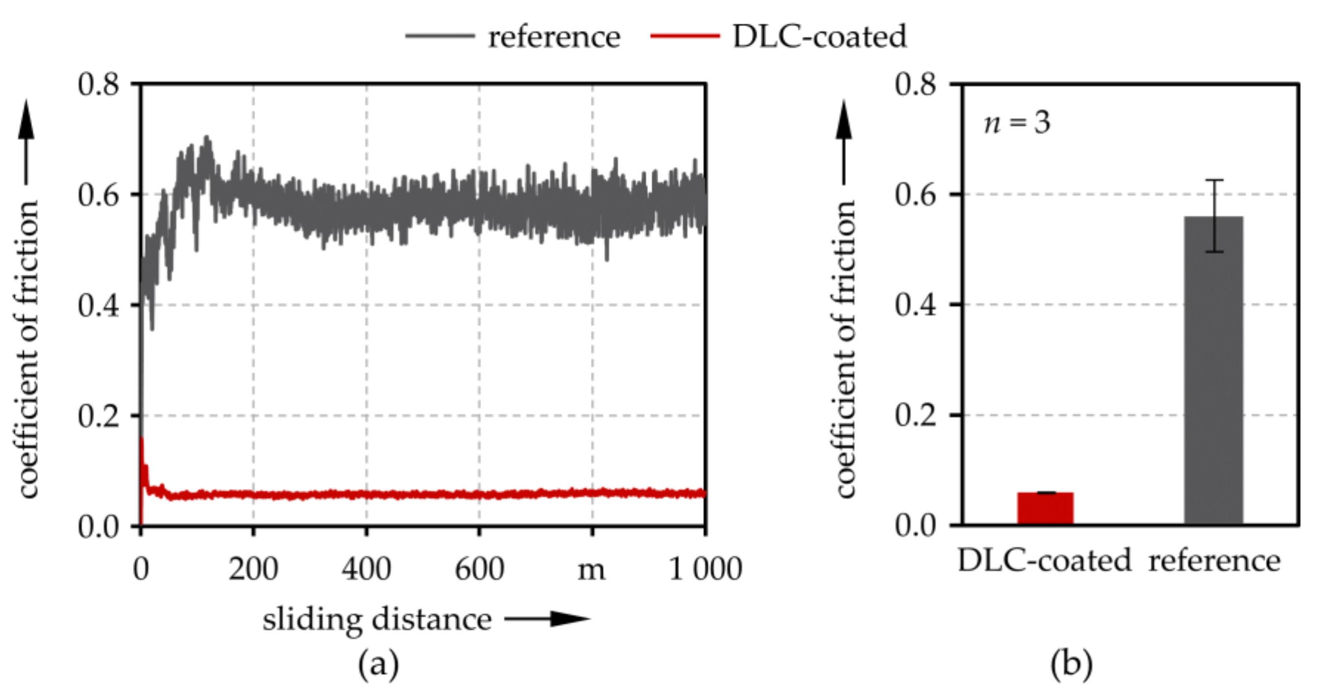
To evaluate the solid friction of uncoated and coated specimens, we performed unlubricated ball-on-disk test (K-SST, KTmfk, Erlangen, Germany) under constant climatic conditions (relative humidity of 40 ± 5% at 23 ± 2 °C); noting that the specimens significantly affect the frictional behavior under mixed lubrication typical for cam/tappet-contacts [49]. Hardened 100Cr6 bearing balls with a diameter of 9.5 mm served as counter-bodies. The applied normal force of 10 N resulted in an initial Hertzian pressure of 1.1 GPa. We selected this force to obtain conditions similar to those in the cam/tappet component-tests after running in. Three uncoated and coated specimens each were tested at the same track radii with a constant rotational sliding velocity of 1.5 m/s and a sliding distance of 1000 m. The coefficient of friction averaged between 600 and 800 m for each test run.

2.2. Numerical Methods

For the numerical TEHL modeling of the cam/bucket tappet-contact, the full-system finite element modeling (FEM) approach, as first presented by Habchi et al. [53], was employed. The calculation model is part of the computation software TriboFEM, which in turn was implemented in Comsol Multiphysics. The main physical and numerical characteristics are briefly described below.

2.2.1. Hydrodynamics

To describe the hydrodynamics, we used a generalized Reynolds equation according to Yang and Wen [54] in a slightly modified form
x 0 h z η d z 0 h ρ 0 z 1 η d z d z 0 h 1 η d z 0 h ρ 0 z z η d z d z p x pressure   /   Poiseuille   term x 0 h ρ 0 z 1 η d z d z 0 h 1 η d z u 1 u 2 + 0 h ρ d z u 2 velocity   /   Couette   term t 0 h ρ d z squeeze   term = 0
with zero pressure boundary conditions at in- and outlet was applied. Cavitation effects were addressed using a mass-conserving model as described by Marian et al. [55]. The Galerkin least squares (GLS) method and isotropic diffusion were used for the numerical stabilization.

2.2.2. Contact Mechanics

The elastic deformation of one body with the equivalent Young’s modulus and Poisson’s ratio was calculated by applying the linear elasticity equation while neglecting inertia effects or body forces:
σ = 0 ,   with   σ = C ε U ,   δ elastic x , t = U v x , t .
Zero displacement at the bottom, as well as zero normal and tangential stress boundary conditions at the sides of the equivalent body, were applied. The effects of the coatings on the mechanical properties were considered by calculating the respective equivalent properties in accordance with Liu et al. [56].
The lubricant film thickness equation
h x , t = h 0 + x 2 2 R x + δ elastic x , t + a texture e ln g a texture mod x x start t u 1 u m + d texture , x 2 ,   d texture , x d texture , x 2 2 w texture , x 2
described the height of the separating fluid film in terms of the distance and shape of the undeformed geometry, the elastic deformation, as well as the geometrical microtexture description.
The load balance equation ensured the equilibrium of forces,
F l = Ω p total x , t   d Ω = Ω p x , t + p solid x , t   d Ω   ,
which also allowed the consideration of simultaneously occurring asperity contact and hydrodynamic lubrication (mixed lubrication) by dividing the total pressure into hydrodynamic and solid contact pressure. Therefore, a statistical approach, as presented by Zhao et al. [57], was applied, while the implementation followed the example by Masjedi and Khonsari [58].
The dimensions of the computational domain were chosen to be large enough so that the results of the calculation corresponded to the results obtained from an infinite elastic half-space approach. Furthermore, a free triangular mesh with a refinement in the contact center of the upper surface was applied.

2.2.3. Thermodynamics

Following Habchi [59], the temperature distribution in the lubricant was described using the energy equation including heat sources due to lubricant compression and shearing
ρ c p T t + u T x convection λ 2 T x 2 + 2 T z 2 heat   condution β p T p t + u p x compression   or   expansion η u z 2 shearing   = 0 ,
while the transient energy equation for the substrates and the coatings was considered as
ρ c p T t + u x T x convection λ 2 T x 2 + 2 T z 2 heat   condution = 0 ,
where i = 1 for the cam and i = 2 for the tappet. The transition between substrate, coating, and lubricant was implemented using temperature and conductive heat flux continuity equations. Solids and lubricant entering the calculation domain were set to bulk temperature while zero conductive heat flux was assumed for the respective properties leaving the domain. Dimensions of the computational domains were chosen so that the heat flux into the substrates became zero. Again, a free triangular mesh with refinement at the boundaries between substrate, coating, and lubricant was applied.

2.2.4. Numerical Procedure

All variables were normalized on initial or Hertzian parameters. The system of EHL equations was solved fully coupled and combined with the energy equations using an iterative procedure. A backward differentiation formula was used for adaptive time stepping. More fundamental aspects of the FEM of TEHL contacts are given by Habchi [59]. For further information about implementation in the software Comsol Multiphysics, the interested reader is referred to Tan et al. [60], Lohner et al. [61], and Weschta [62].

2.2.5. Load Cases, Material and Lubricant Properties

Relevant mechanical, thermal bulk and coating properties were chosen based on the measurement or literature values and they are summarized in Table 2. Pressure and temperature dependency of the lubricant was modeled according to Roelands (Sadeghi and Sui [63]), whereas a modified Carreau-Yasuda model described the shear dependency in accordance with Bair [64]. Density was modeled pressure and temperature-dependent according to Dowson and Higginson [65]. The relevant lubricant properties are summed up in Table 3.
Derived from multibody dynamics analysis (Weschta [62]), three different load cases corresponding to the contact between the cam tip and tappet at 500 min−1 (Moes parameters M = 9.3, L = 8.1, SRR = −2.6), 1000 min−1 (M = 6.3, L = 9,7, SRR = −2.6), and 2000 min−1 (M = 3.6, L = 11.5, SRR = −2.6), were studied within the scope of this manuscript.
For evaluation of the friction reduction mechanisms induced by microtexturing and amorphous carbon coating, we calculated the changes in the fluid friction force from integrating the shear stress in the middle of the lubricant film [59]
F fluid = x inlet x outlet τ zx z = h / 2 d x
and changes to the solid friction force from integrating the product of solid contact pressure and the dry friction coefficient [27]
F solid = x inlet x outlet μ solid p solid d x .

3. Results and Discussion

3.1. Experimental Results

Representative LSM-measurements of a microtextured surface and a FIB-milled cross-section of the amorphous carbon coating are depicted in Figure 1a,b, respectively. It can be seen that the textures were fabricated with high shape accuracy and precision, showing well defined structural parameters such as depth, width, and lateral distance. For the coating, we determined a thickness of approximately 2 μm, an indentation hardness HIT of 15.8 ± 0.5 GPa, and an indentation modulus EIT of 110.9 ± 3.3 GPa. Therefore, compared to the substrate (HIT = 8.3 ± 0.2 GPa, EIT = 216.5 ± 2.5 GPa), the coating was harder, though elastically less stiff.
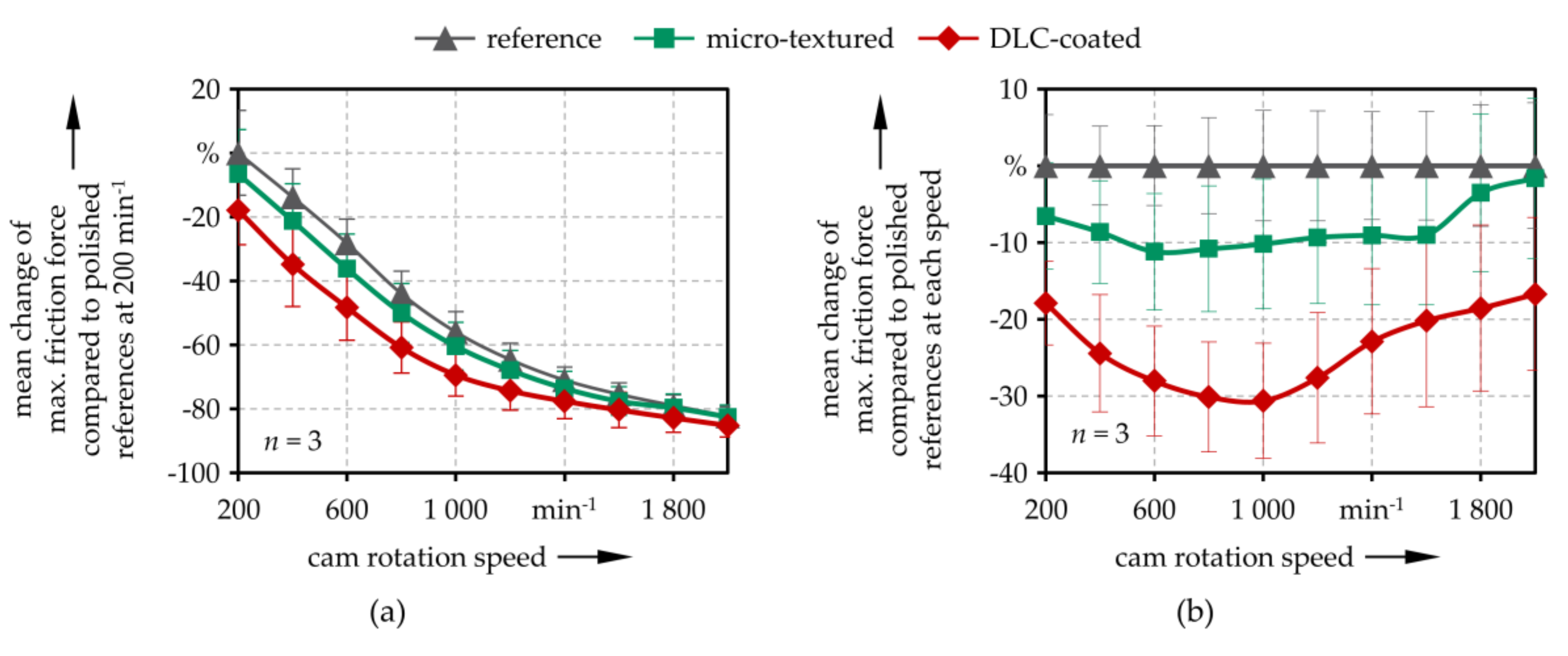
Since we found no significant wear after the performance of the short-term component-test, the following evaluations refer purely to the frictional behavior. Therefore, the maximum detected friction force was averaged for all revolutions within the respective measurement ramp of each specimen. Subsequently, we calculated the mean values of all three samples for the reference, microtextured, and DLC-coated tappet. Corresponding results in dependency of the cam rotation speed are summarized in Figure 2, normalized to the polished references at the first speed level (a), and to the polished references at each speed level (b). All specimens featured a continuous Stribeck-like decrease of friction with an increasing camshaft speed.
A reduction of friction up to 12% compared to the references was achieved by micro-texturing. It can be assumed that the solid–solid contact ratio was reduced during contact between the counter-body and the texture [49]. In addition, the build-up of an additional hydrodynamic pressure can be expected. However, friction reduction was pronounced more strongly for lower camshaft speeds, and the measured values almost reached the reference level at higher speeds. The result matched well with observations previously made in the literature [24]. However, since the considered cam/tappet pairing works under mixed lubrication conditions in the whole speed range tested [49,62], the complete separation of rubbing surfaces, and thus, a loss of texture induced effects alone does not provide a sufficient explanation.
For the amorphous carbon coating, a friction reduction of up to 31% was observed. Contrary to the microtextured specimens, the coated specimens did not fully reach the reference level but featured a significant friction decrease of at least 17% for all cam rotation speeds. As far as solid friction was concerned, these observations could be attributed to a lower coefficient of friction as measured in the dry ball-on-disk experiments and depicted in Figure 3a,b. However, the highest reduction was recorded in the medium speed range. Therefore, besides surface energy and spreading parameters of the lubricant, the shear-thinning effects induced by thermal insulation could also influence the fluid friction behavior. However, the relative friction reduction decreased at higher speed levels.

3.2. Numerical Results

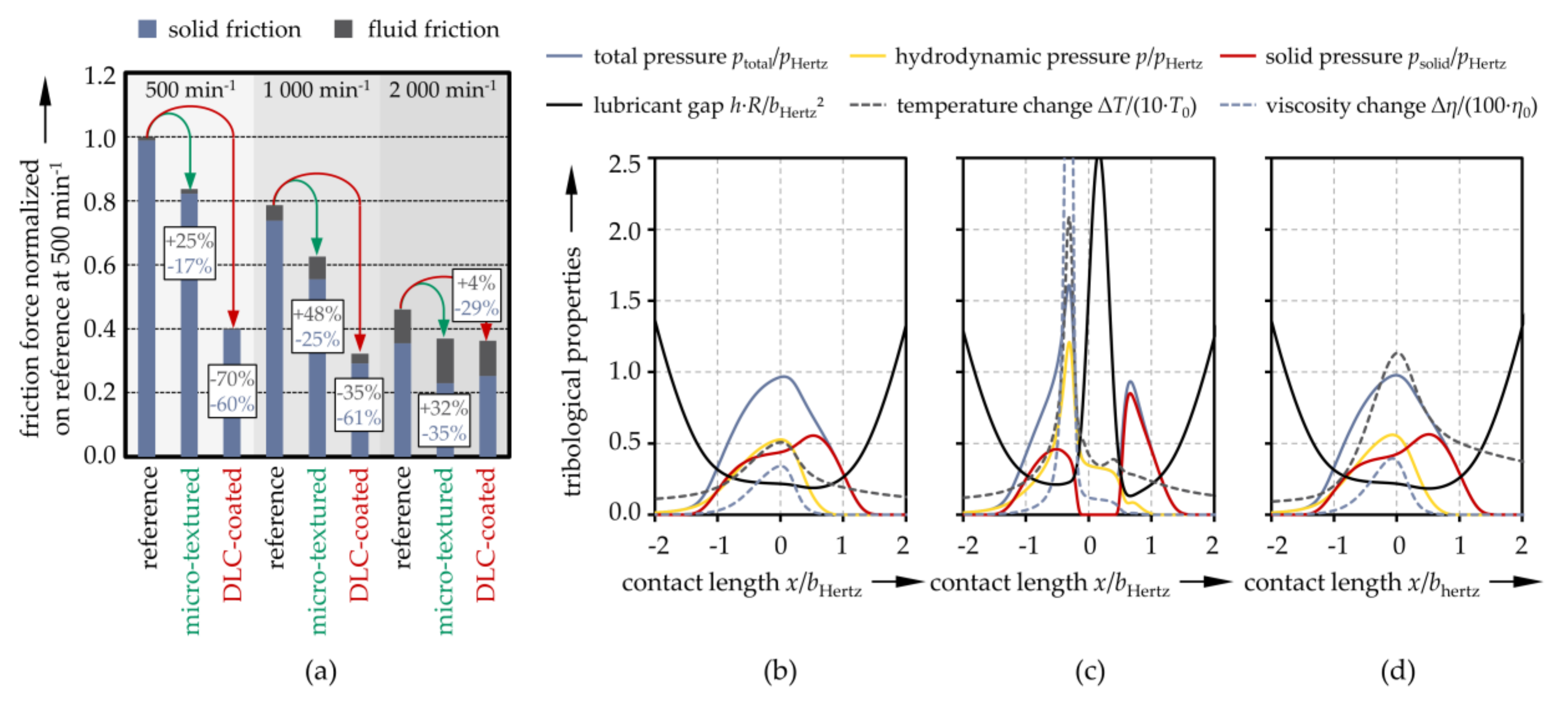
An overview of the computed friction force, which is normalized to the first speed level and divided into its fraction of solid and fluid friction, is shown in Figure 4a. Furthermore, the representative plots of the characteristic properties along the contact length at the medium speed level for the reference, the microtextured case, and the coated case, are provided in Figure 4b–d. Similar to the experiments, a Stribeck-like decrease of total friction, as well as the declining fraction of solid friction and increasing fluid friction with cam rotation speed, was observed for all cases.
The total friction reduction from microtexturing and amorphous carbon coating was pronounced more strongly at lower speed levels, as observed in the experiments. The first featured reduced solid friction and increased fluid friction. Besides a local constriction in the lubricant gap and an additional pressure increase, the trailing effects in the area behind the texture induced enlargement of the lubricant gap, thereby reducing the overall asperity contact and solid contact pressure. Similar to other studies reported in the literature, this could be explained by lubricant drawn out of the texture due to the elastic deformation and velocity differences of the rubbing surfaces [40], which increased the viscosity and built additional hydrodynamic pressure (Figure 4c). However, this also meant an increase in the fraction of fluid friction as the lubricant became more shear-resistant. At higher speed levels, despite the decreased solid friction, the reference and microtexturing converge due to the higher fluid friction of the latter. On the contrary, amorphous carbon coating could reduce both solid and fluid friction. The result was due to a lower solid friction coefficient of the coated surface and the thermal insulation effect. Therefore, the viscosity, and thus, the shear resistance of the lubricant was reduced due to a temperature increase (Figure 4d), which resulted from the lower thermal diffusivity of the coating. However, at higher speed levels, the amorphous carbon coating also approached the reference level due to the negative slide-to-roll-ratio. This outcome led to higher temperatures at the contact inlet, and thus, lower fluid film thickness. In turn, this might even lead to an increased fraction of fluid friction. Thus, the simulation results matched well with the literature and experimental observations. Slight quantitative discrepancies could be attributed, for example, to simplifications in modeling the TEHL cam/tappet-contact, such as the negligence of edge effects due to the 2D assumption, as well as deviations in the assumed material, coating, and fluid properties from the real ones.

4. Conclusions

Tribological cam/bucket tappet component tests were performed to determine the friction behavior of ultrashort pulse laser fabricated microtextures and PVD/PECVD deposited silicon-doped hydrogenated amorphous carbon coatings. Within the scope of this study, a significant friction reduction of over ten and up to thirty percent was achieved from microtexturing and amorphous carbon coating, respectively. Furthermore, TEHL tribo-simulations acted as a ‘numerical zoom’ into the contact area and contributed to the numerical explanation of the tribological behavior. It was shown that microtexturing could reduce the fraction of solid friction while increasing fluid friction. The result was due to trailing effects with lubricant being emitted from the texture, locally increasing viscosity, enlarging the lubricant gap and reducing asperity contact. The effect resembled a counterclockwise tilt of the Stribeck curve. Contrarily, amorphous carbon coatings could reduce solid and fluid friction, which could be interpreted as a shift of the Stribeck curve to the lower left. This was due to lower dry friction and lower thermal inertia of the coating. It should be noted that the change in frictional behavior induced by the studied surface modifications was highly dependent on application conditions. For example, potentially positive effects could be consumed in the case of microtextured contacts with higher sliding speeds or in the case of amorphous carbon coatings in contacts with opposing moving surfaces at high velocities. Therefore, the TEHL simulations can be used as preliminary studies to estimate the effects of such surface modifications on the tribological behavior in each case. However, this study showed the potential of both microtexturing and the application of amorphous carbon coatings to improve the energy efficiency of the cam/tappet-contact in a wide range of rotational speeds. However, the results are certainly not limited to the investigated application in combustion engines, as the findings can also be considered for the optimization of other tribological contacts such as in electric vehicles.

Author Contributions

Conceptualization and methodology of experimental studies, M.M. and T.W.; Component tests and data analysis, M.M.; Specimen preparation and micro-texturing, M.M.; DLC-coating deposition, T.W.; Tribological and mechanical analysis, T.W.; Conceptualization and analysis of numerical studies, M.M.; Original draft preparation, M.M. and T.W.; Review and editing, S.T.; Supervision, project administration, and funding acquisition, S.T.

Funding

This research was funded partly by the German Federal Ministry for Economic Affairs and Energy (BMWi) under grant number 03ET1609H (PROMETHEUS), as well as partly by the German Research Foundation (DFG) under project SFB/TR 73 TP B4.

Acknowledgments

The authors greatly acknowledge the continuous support of the technical faculty and the mechanical engineering department of Friedrich-Alexander-Universität (FAU) Erlangen-Nürnberg, Germany. T. Häfner from Bayerisches Laserzentrum GmbH (BLZ) in Erlangen, Germany, is thanked for the microtexturing of the specimens. Furthermore, Ing U. Wolf from Engineering Design and Ing. B. Merle and S. Gabel, M.Sc. from the General Materials Properties Institute (all FAU Erlangen Nürnberg, Germany) are thanked for their assistance in the tribological characterization and FIB-preparation of the coating, respectively.

Conflicts of Interest

The authors declare no conflict of interest. The funders had no role in the design of the study; in the collection, analyses, or interpretation of data; in the writing of the manuscript, or in the decision to publish the results.

Nomenclature

acCarreau parameter
atexturemicro-texture amplitude
bHertzHertzian contact half-width
cpspecific heat capacity
Ccompliance matrix
dtexturemicro-texture distance
EYoung’s modulus
EITindentation modulus
Fnormal force
Ffluidfluid friction force
Fsolidsolid friction force
gzero level correction parameter
Gccritical shear stress
hlubricant gap
h0rigid body motion
HITindentation hardness
lcam width in y-direction
LMoe’s dimensionless material properties parameter
MMoe’s dimensionless load parameter
ncCarreau parameter
phydrodynamic pressure
pHertzHertzian contact pressure
psolidsolid contact pressure
ptotaltotal contact pressure
Requivalent radius
SRRslide-to-roll ratio
u1sliding velocity of body 1
u2sliding velocity of body 2
ummean hydrodynamic velocity
Uzdisplacement in z-direction
ttime
Ttemperature
wtexturemicro-texture width in x-direction
x, y, zspace coordinates
xstartstarting position of the micro-texture in x-direction
αppressure viscosity coefficient
βpvolume expansion coefficient
βηRoelands temperature viscosity coefficient
δelasticelastic deformation in z-direction
εstrain tensor
ηlubricant viscosity
η0lubricant viscosity at reference state
λthermal conductivity
μsolidsolid friction coefficient
ρdensity
σstress tensor of the equivalent body
τzxshear stress
υPoisson’s ratio
Ωcomputational domain

References

  1. Holmberg, K.; Andersson, P.; Erdemir, A. Global energy consumption due to friction in passenger cars. Tribol. Int. 2012, 47, 221–234. [Google Scholar] [CrossRef]
  2. Kalghatgi, G. Is it really the end of internal combustion engines and petroleum in transport? Appl. Energy 2018, 225, 965–974. [Google Scholar] [CrossRef]
  3. Serrano, J.R.; Novella, R.; Piqueras, P. Why the development of internal combustion engines is still necessary to fight against global climate change from the perspective of transportation. Appl. Sci. 2019, 9, 4597. [Google Scholar] [CrossRef] [Green Version]
  4. Farfan-Cabrera, L.I. Tribology of electric vehicles: A review of critical components, current state and future improvement trends. Tribol. Int. 2019, 138, 473–486. [Google Scholar] [CrossRef]
  5. Holmberg, K.; Erdemir, A. Influence of tribology on global energy consumption, costs and emissions. Friction 2017, 5, 263–284. [Google Scholar] [CrossRef]
  6. Kalin, M.; Velkavrh, I.; Vižintin, J.; Ožbolt, L. Review of boundary lubrication mechanisms of DLC coatings used in mechanical applications. Meccanica 2008, 43, 623–637. [Google Scholar] [CrossRef]
  7. Erdemir, A.; Donnet, C. Tribology of diamond-like carbon films: Recent progress and future prospects. J. Phys. D Appl. Phys. 2006, 39, R311–R327. [Google Scholar] [CrossRef]
  8. Gropper, D.; Wang, L.; Harvey, T.J. Hydrodynamic lubrication of textured surfaces: A review of modeling techniques and key findings. Tribol. Int. 2016, 94, 509–529. [Google Scholar] [CrossRef] [Green Version]
  9. Gachot, C.; Rosenkranz, A.; Hsu, S.M.; Costa, H.L. A critical assessment of surface texturing for friction and wear improvement. Wear 2017, 372–373, 21–41. [Google Scholar] [CrossRef]
  10. Rosenkranz, A.; Grützmacher, P.G.; Gachot, C.; Costa, H.L. Surface texturing in machine elements—A critical discussion for rolling and sliding contacts. Adv. Eng. Mater. 2019, 86, 1900194. [Google Scholar] [CrossRef]
  11. Grützmacher, P.G.; Profito, F.J.; Rosenkranz, A. Multi-scale surface texturing in tribology—Current knowledge and future perspectives. Lubricants 2019, 7, 95. [Google Scholar] [CrossRef] [Green Version]
  12. Pettersson, U.; Jacobson, S. Textured surfaces in sliding boundary lubricated contacts—Mechanisms, possibilities and limitations. Tribol. Mater. Surf. Interfaces 2013, 1, 181–189. [Google Scholar] [CrossRef]
  13. Löffler, M.; Andreas, K.; Engel, U.; Schulte, R.; Groebel, D.; Krebs, E.; Freiburg, D.; Biermann, D.; Stangier, D.; Tillmann, W.; et al. Tribological measures for controlling material flow in sheet-bulk metal forming. Prod. Eng. 2016, 10, 459–470. [Google Scholar] [CrossRef]
  14. Borghi, A.; Gualtieri, E.; Marchetto, D.; Moretti, L.; Valeri, S. Tribological effects of surface texturing on nitriding steel for high-performance engine applications. Wear 2008, 265, 1046–1051. [Google Scholar] [CrossRef]
  15. Etsion, I. Modeling of surface texturing in hydrodynamic lubrication. Friction 2013, 1, 195–209. [Google Scholar] [CrossRef] [Green Version]
  16. Wos, S.; Koszela, W.; Pawlus, P. Tribological behaviours of textured surfaces under conformal and non-conformal starved lubricated contact conditions. Proc. Inst. Mech. Eng. Part J J. Eng. Tribol. 2015, 229, 398–409. [Google Scholar] [CrossRef]
  17. Grabon, W.; Koszela, W.; Pawlus, P.; Ochwat, S. Improving tribological behaviour of piston ring–cylinder liner frictional pair by liner surface texturing. Tribol. Int. 2013, 61, 102–108. [Google Scholar] [CrossRef]
  18. Evans, R.D.; Cogdell, J.D.; Richter, G.A.; Doll, G.L. Traction of lubricated rolling contacts between thin-film coatings and steel. Tribol. Trans. 2008, 52, 106–113. [Google Scholar] [CrossRef]
  19. Kalin, M.; Polajnar, M. The wetting of steel, DLC coatings, ceramics and polymers with oils and water: The importance and correlations of surface energy, surface tension, contact angle and spreading. Appl. Surf. Sci. 2014, 293, 97–108. [Google Scholar] [CrossRef]
  20. Kalin, M.; Polajnar, M. The effect of wetting and surface energy on the friction and slip in oil-lubricated contacts. Tribol. Lett. 2013, 52, 185–194. [Google Scholar] [CrossRef]
  21. Björling, M.; Larsson, R.; Marklund, P. The Effect of DLC Coating Thickness on Elstohydrodynamic Friction. Tribol. Lett. 2014, 55, 353–362. [Google Scholar] [CrossRef] [Green Version]
  22. Björling, M.; Habchi, W.; Bair, S.; Larsson, R.; Marklund, P. Friction Reduction in Elastohydrodynamic Contacts by Thin-Layer Thermal Insulation. Tribol. Lett. 2014, 53, 477–486. [Google Scholar] [CrossRef] [Green Version]
  23. Björling, M.; Isaksson, P.; Marklund, P.; Larsson, R. The Influence of DLC Coating on EHL Friction Coefficient. Tribol. Lett. 2012, 47, 285–294. [Google Scholar] [CrossRef] [Green Version]
  24. Bobzin, K.; Brögelmann, T.; Stahl, K.; Michaelis, K.; Mayer, J.; Hinterstoißer, M. Friction reduction of highly-loaded rolling-sliding contacts by surface modifications under elasto-hydrodynamic lubrication. Wear 2015, 328–329, 217–228. [Google Scholar] [CrossRef]
  25. Elsharkawy, A.A.; Hamrock, B.J. EHL of Coated Surfaces: Part I—Newtonian Results. J. Tribol. 1994, 116, 29. [Google Scholar] [CrossRef]
  26. Habchi, W. A numerical model for the solution of thermal elastohydrodynamic lubrication in coated circular contacts. Tribol. Int. 2014, 73, 57–68. [Google Scholar] [CrossRef]
  27. Bobach, L.; Bartel, D.; Beilicke, R.; Mayer, J.; Michaelis, K.; Stahl, K.; Bachmann, S.; Schnagl, J.; Ziegele, H. Reduction in EHL Friction by a DLC Coating. Tribol. Lett. 2015, 60, 1270. [Google Scholar] [CrossRef]
  28. Ebner, M.; Ziegltrum, A.; Lohner, T.; Michaelis, K.; Stahl, K. Measurement of EHL temperature by thin film sensors—Thermal insulation effects. Tribol. Int. 2018, 105515. [Google Scholar] [CrossRef]
  29. Choo, J.W.; Olver, A.V.; Spikes, H.A. The influence of transverse roughness in thin film, mixed elastohydrodynamic lubrication. Tribol. Int. 2007, 40, 220–232. [Google Scholar] [CrossRef]
  30. Choo, J.W.; Olver, A.V.; Spikes, H.A.; Dumont, M.-L.; Ioannides, E. The Influence of Longitudinal Roughness in Thin-Film, Mixed Elastohydrodynamic Lubrication. Tribol. Trans. 2006, 49, 248–259. [Google Scholar] [CrossRef]
  31. Ehret, P.; Dowson, D.; Taylor, C.M. Waviness Orientation in EHL Point Contact. In The Third Body Concept Interpretation of Tribological Phenomena; Elsevier: Amsterdam, The Netherlands, 1996; pp. 235–244. ISBN 9780444825025. [Google Scholar]
  32. Venner, C.H.; Lubrecht, A.A. Numerical Simulation of a Transverse Ridge in a Circular EHL Contact Under Rolling/Sliding. J. Tribol. 1994, 116, 751. [Google Scholar] [CrossRef]
  33. Cusano, C.; Wedeven, L.D. The Effects of Artificially-Produced Defects on the Film Thickness Distribution in Sliding EHD Point Contacts. J. Lubr. Technol. 1982, 104, 365. [Google Scholar] [CrossRef] [Green Version]
  34. Ai, X.; Cheng, H.S. The Influence of Moving Dent on Point EHL Contacts. Tribol. Trans. 1994, 37, 323–335. [Google Scholar] [CrossRef]
  35. Mourier, L.; Mazuyer, D.; Lubrecht, A.A.; Donnet, C. Transient increase of film thickness in micro-textured EHL contacts. Tribol. Int. 2006, 39, 1745–1756. [Google Scholar] [CrossRef]
  36. Mourier, L.; Mazuyer, D.; Ninove, F.-P.; Lubrecht, A.A. Lubrication mechanisms with laser-surface-textured surfaces in elastohydrodynamic regime. Proc. Inst. Mech. Eng. Part. J J. Eng. Tribol. 2010, 224, 697–711. [Google Scholar] [CrossRef]
  37. Krupka, I.; Hartl, M. The effect of surface texturing on thin EHD lubrication films. Tribol. Int. 2007, 40, 1100–1110. [Google Scholar] [CrossRef]
  38. Krupka, I.; Vrbka, M.; Hartl, M. Effect of surface texturing on mixed lubricated non-conformal contacts. Tribol. Int. 2008, 41, 1063–1073. [Google Scholar] [CrossRef]
  39. Rosenkranz, A.; Szurdak, A.; Gachot, C.; Hirt, G.; Mücklich, F. Friction reduction under mixed and full film EHL induced by hot micro-coined surface patterns. Tribol. Int. 2016, 95, 290–297. [Google Scholar] [CrossRef]
  40. Marian, M.; Grützmacher, P.; Rosenkranz, A.; Tremmel, S.; Mücklich, F.; Wartzack, S. Designing surface textures for EHL point-contacts—Transient 3D simulations, meta-modeling and experimental validation. Tribol. Int. 2019, 137, 152–163. [Google Scholar] [CrossRef]
  41. Beilicke, R.; Bobach, L.; Bartel, D. Transient thermal elastohydrodynamic simulation of a DLC coated helical gear pair considering limiting shear stress behavior of the lubricant. Tribol. Int. 2016, 97, 136–150. [Google Scholar] [CrossRef]
  42. Ziegltrum, A.; Lohner, T.; Stahl, K. TEHL Simulation on the Influence of Lubricants on the Frictional Losses of DLC Coated Gears. Lubricants 2018, 6, 17. [Google Scholar] [CrossRef] [Green Version]
  43. Kano, M. Super low friction of DLC applied to engine cam follower lubricated with ester-containing oil. Tribol. Int. 2006, 39, 1682–1685. [Google Scholar] [CrossRef]
  44. Dobrenizki, L.; Tremmel, S.; Wartzack, S.; Hoffmann, D.C.; Brögelmann, T.; Bobzin, K.; Bagcivan, N.; Musayev, Y.; Hosenfeldt, T. Efficiency improvement in automobile bucket tappet/camshaft contacts by DLC coatings—Influence of engine oil, temperature and camshaft speed. Surf. Coat. Technol. 2016, 308, 360–373. [Google Scholar] [CrossRef]
  45. Yu, C.; Meng, X.; Xie, Y. Numerical simulation of the effects of coating on thermal elastohydrodynamic lubrication in cam/tappet contact. Proc. Inst. Mech. Eng. Part. J J. Eng. Tribol. 2017, 231, 221–239. [Google Scholar] [CrossRef]
  46. Meng, X.; Yu, C.; Xie, Y.; Mei, B. Thermal insulation effect on EHL of coated cam/tappet contact during start up. Ind. Lubr. Tribol. 2018, 70, 917–926. [Google Scholar] [CrossRef]
  47. Gangopadhyay, A.; McWatt, D.G. The Effect of Novel Surface Textures on Tappet Shims on Valvetrain Friction and Wear. Tribol. Trans. 2008, 51, 221–230. [Google Scholar] [CrossRef]
  48. Krupka, I.; Hartl, M.; Zimmerman, M.; Houska, P.; Jang, S. Effect of surface texturing on elastohydrodynamically lubricated contact under transient speed conditions. Tribol. Int. 2011, 44, 1144–1150. [Google Scholar] [CrossRef]
  49. Marian, M.; Tremmel, S.; Wartzack, S. Microtextured surfaces in higher loaded rolling-sliding EHL line-contacts. Tribol. Int. 2018, 127, 420–432. [Google Scholar] [CrossRef]
  50. Tremmel, S.; Marian, M.; Zahner, M.; Wartzack, S.; Merklein, M. Friction reduction in EHL contacts by surface microtexturing—Tribological performance, manufacturing and tailored design. Ind. Lubr. Tribol. 2018, 0306. [Google Scholar] [CrossRef]
  51. Marian, M.; Weikert, T.; Tremmel, S. Numerical and experimental studies on friction reduction by surface modification in TEHL contacts. In Proceedings of the STLE 2019—74th Annual Meeting and Exhibition of the Society of Tribologists and Lubrication Engineers, Nashville, TN, USA, 19–23 May 2019. [Google Scholar]
  52. ISO 14577-1:2015. Metallic Materials—Instrumented Indentation Test for Hardness and Materials Parameters—Part. 1: Test, Method; International Organization for Standardization: Geneva, Switzerland, 2015. [Google Scholar]
  53. Habchi, W.; Demirci, I.; Eyheramendy, D.; Morales-Espejel, G.; Vergne, P. A finite element approach of thin film lubrication in circular EHD contacts. Tribol. Int. 2007, 40, 1466–1473. [Google Scholar] [CrossRef]
  54. Yang, P.; Wen, S. A Generalized Reynolds Equation for Non-Newtonian Thermal Elastohydrodynamic Lubrication. J. Tribol. 1990, 112, 631–636. [Google Scholar] [CrossRef]
  55. Marian, M.; Weschta, M.; Tremmel, S.; Wartzack, S. Simulation of Microtextured Surfaces in Starved EHL Contacts Using Commercial FE Software. Mater. Perform. Charact. 2017, 6, 165–181. [Google Scholar] [CrossRef]
  56. Liu, S.; Peyronnel, A.; Wang, Q.J.; Keer, L.M. An extension of the Hertz theory for 2D coated components. Tribol. Lett. 2005, 18, 505–511. [Google Scholar] [CrossRef]
  57. Zhao, Y.; Maietta, D.M.; Chang, L. An Asperity Microcontact Model Incorporating the Transition from Elastic Deformation to Fully Plastic Flow. J. Tribol. 2000, 122, 86. [Google Scholar] [CrossRef]
  58. Masjedi, M.; Khonsari, M.M. Film Thickness and Asperity Load Formulas for Line-Contact Elastohydrodynamic Lubrication With Provision for Surface Roughness. J. Tribol. 2012, 134, 11503. [Google Scholar] [CrossRef]
  59. Habchi, W. Finite Element Modeling of Elastohydrodynamic Lubrication Problems; John Wiley & Sons Incorporated: Newark, NJ, USA, 2018; ISBN 978-1119225126. [Google Scholar]
  60. Tan, X.; Goodyer, C.E.; Jimack, P.K.; Taylor, R.I.; Walkley, M.A. Computational approaches for modelling elastohydrodynamic lubrication using multiphysics software. Proc. Inst. Mech. Eng. Part. J J. Eng. Tribol. 2012, 226, 463–480. [Google Scholar] [CrossRef]
  61. Lohner, T.; Ziegltrum, A.; Stemplinger, J.-P.; Stahl, K. Engineering Software Solution for Thermal Elastohydrodynamic Lubrication Using Multiphysics Software. Adv. Tribol. 2016, 2016, 1–13. [Google Scholar] [CrossRef] [Green Version]
  62. Weschta, M. Untersuchungen zur Wirkungsweise von Mikrotexturen in elastohydrodynamischen Gleit/Wälz-Kontakten. Ph.D. Thesis, Friedrich-Alexander-Universität, Erlangen-Nürnberg, Germany, 2017. urn:nbn:de:bvb:29-opus4-91095. [Google Scholar]
  63. Sadeghi, F.; Sui, P.C. Thermal Elastohydrodynamic Lubrication of Rolling/Sliding Contacts. J. Tribol. 1990, 112, 189–195. [Google Scholar] [CrossRef]
  64. Bair, S. A Rough Shear-Thinning Correction for EHD Film Thickness. Tribol. Trans. 2004, 47, 361–365. [Google Scholar] [CrossRef]
  65. Dowson, D.; Higginson, G.R. Elasto-Hydrodynamic Lubrication, SI ed.; Pergamon Press: Oxford, UK, 1977; ISBN 0080213022. [Google Scholar]
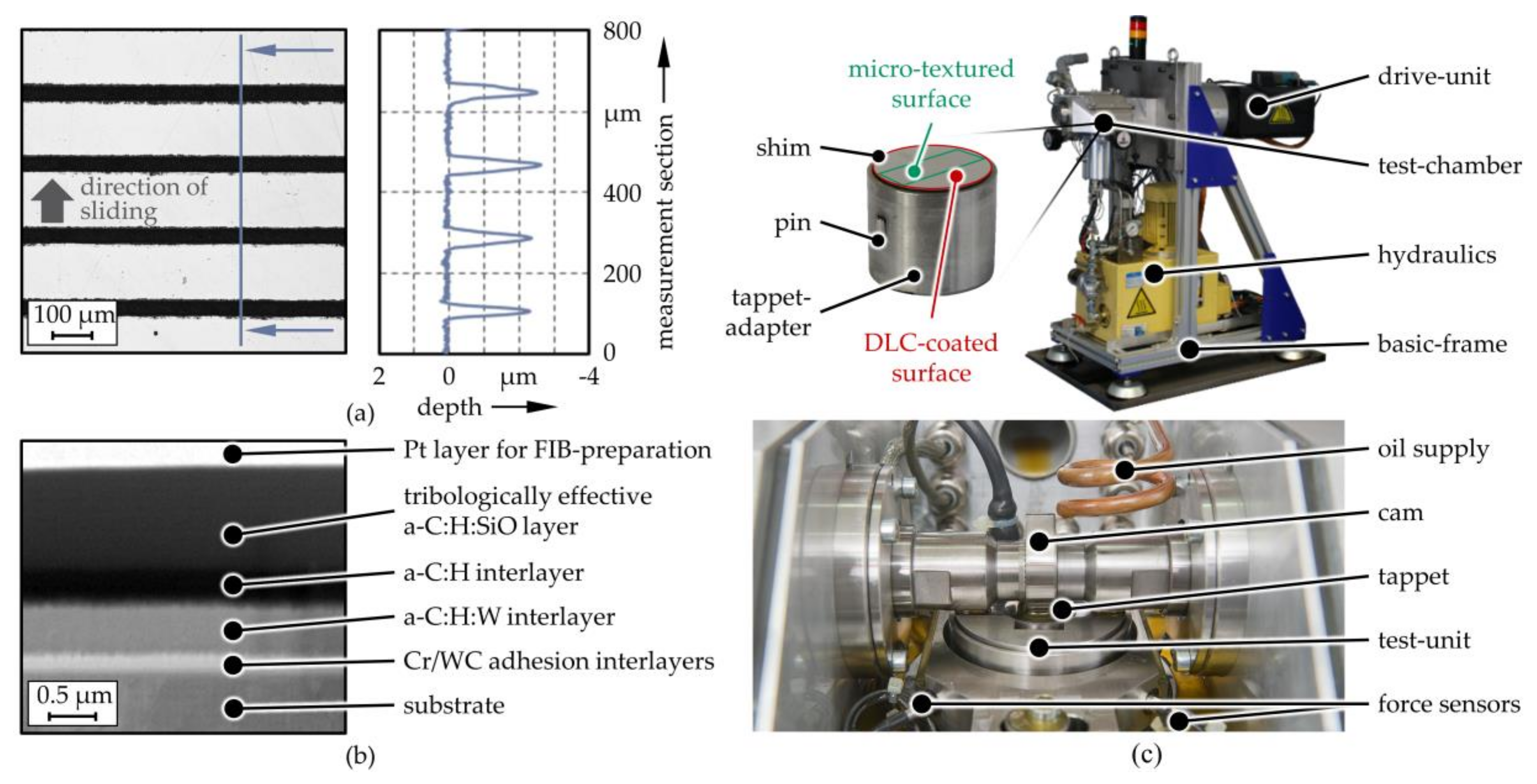
Figure 1. (a) Laser scanning microscopy image and a sectional view of a microtextured sample; (b) FIB-milled cross-section of a DLC-coated specimen; (c) Cam/bucket tappet component test-rig.
Coatings 09 00843 g001
Figure 2. Mean change of friction force in the cam/tappet-contact for the microtextured and DLC-coated specimens at different cam rotation speeds compared to the polished references (a) at the first speed level and (b) at each speed level.
Coatings 09 00843 g002
Figure 3. Coefficient of friction of the reference and DLC-coated specimens under dry conditions (a) over the sliding distance of one exemplary test-run and (b) as the averaged value.
Coatings 09 00843 g003
Figure 4. (a) Computed solid and fluid friction force for the reference, microtextured, and DLC-coated case, normalized total, hydrodynamic and solid contact pressure, lubricant gap, temperature, and viscosity change for the (b) reference, (c) microtextured, and (d) DLC-coated case.
Coatings 09 00843 g004
Table 1. Deposition parameters of layers of the amorphous carbon coating according to the order of deposition.
Coating LayerDuration in sArc Current of Cr-Target in ASputtering Power of WC-Target in WBias Voltage in V (Operating Mode)Acetylene Gas Flow in sccmArgon Gas Flow in sccmHMDSO Gas Flow in sccmTemperature in °C
Cr28070−100 (DC)70140
WC10801200−50 (DC)195110
a-C:H:W22671200−130 (DC)28180100
a-C:H1155−450 (bipolar pulsed)250100100
a-C:H:SiO2050−575 (unipolar pulsed)2501006100
Table 2. Material properties.
ParameterCam(100Cr6)Tappet (16MnCr5)Coating (a-C:H:SiO)
Young’s/indentation modulus E in MPa209,000 1216,000 2110,000 2
Poisson’s ratio ν0.3 10.3 10.3 1
density ρ in kg/m³7850 17760 14655 1
thermal conductivity λ in W/(m∙K)47 144 11.1 1
specific heat capacity cp in J/(kg∙K)460 1431 18263 1
dry coefficient of friction against 100Cr6 μsolid0.5 2, 30.2 2,3
1 based upon literature [41,42]. 2 based upon measurements, see Section 3.1. 3 conservative estimation compared to measurement results in Section 3.1.
Table 3. Lubricant properties [62].
Base Density at 90 °C ρ in kg/m³840
Base Viscosity at 90 °C η0 in Pa∙s0.03
Pressure Viscosity Coefficient αp in Pa−1,1.31∙10−8
Roelands Temperature Coefficient βη0.042
Critical Shear Stress Gc0.2 η0
Carreau Parameter ac2.2
Carreau Parameter nc0.8
Thermal Conductivity λ in W/(m∙K)0.14
Specific Heat Capacity cp in J/(kg∙K)2000