Article

Calcium Phosphate Layers Deposited on Thermal Sensitive Polymer Substrates in Radio Frequency Magnetron Plasma Discharge

National Institute for Laser, Plasma and Radiation Physics, 409 Atomistilor Street, P.O. Box MG 36, Magurele, 077125 Bucharest, Romania
*
Author to whom correspondence should be addressed.
Coatings 2019, 9(11), 709; https://doi.org/10.3390/coatings9110709
Submission received: 10 September 2019 / Revised: 22 October 2019 / Accepted: 26 October 2019 / Published: 30 October 2019
(This article belongs to the Special Issue Biomedical Applications of Functional Nanoparticles)

Abstract

:
Calcium phosphate coatings were deposited on thermally sensitive polyprophylene substrates in radio frequency (rf) magnetron sputtering discharge. The steady state of the deposition plasma and its components were identified by deposition rate measurements and mass spectrometry. Low rf powers and deposition rates, with a 10 min plasma on/off temporal deposition scheme, were established as suitable experimental conditions for the deposition of calcium phosphate layers on the thermoplastic polymers. By scanning electron microscopy and atomic force microscopy, the influence of the polymer substrate heating to the surface coating topography was studied. The results showed that the thermal patterning of the polymers during the plasma deposition process favors the embedding of the calcium phosphate into the substrate, the increase of the coating surface roughness, and a good adherence of the layers. The layers generated in the 10 min plasma on/10 min plasma off deposition conditions were not cracked or exfoliated. The Fourier Transform Infrared spectra of the polyprophylene substrates presented similar molecular bands before and after the depositions of calcium phosphate layers.

1. Introduction

Calcium phosphate ceramic coatings represent a class of biomaterials widely used in biomedical applications, such as bone substitution and bone regeneration, due to the biocompatible, non-toxic, bioresorbable properties, as well as the similarities of their chemical composition with the inorganic component of bone structures [1]. A great biocompatible material requires a good implant–bone cell connection after the insertion of the implant in the human body to sustain new bone formation, adherence to tissues and to induce the growth of peripheral tissues [1,2,3,4,5]. In recent studies it was demonstrated that the osteointegration of the orthopedic prosthesis could be increased by covering the implant surfaces with calcium phosphate (CaP) bioactive coatings, which prove to accelerate the bone-bonding rate [1,3].
Thermoplastic polymers are biocompatible, inert, and hydrophobic materials, being considered important for various purposes in the biomedical field, as they do not degrade in vivo. As a function of their molecular weight, they are used in different medical applications, such as implantation, tissue regeneration [6], suture material fibers or meshes [6,7,8]. By combining polymer materials with calcium phosphate compounds, it was possible to imitate the structure and match the mechanical properties of bones. It was proven that the incorporation of high percentages of calcium phosphate particles in the polymer matrix allows a good bioactivity of the composite [4,5,9].
A large number of methods, including magnetron sputtering, thermal plasma spraying, biomimetic crystallization methods, pulsed laser deposition, sol-gel coatings or electrospinning, are currently used for the deposition of multicomponent materials, such as CaP [1,4,5,6,7,8]. In rf magnetron sputtering discharges, such layers have been generated on different kind of substrates (metallic or polymeric) with planar or complex shapes, by maintaining the temperature at the substrate during the depositions between 50–70 °C [5,9]. The coatings have uniform thicknesses, high purity, and good adhesion to the substrate [3,7,8,9]. The heating of the substrate during the deposition process is usually attributed to the kinetic energy of the atoms and fragments of the deposited material which attain the substrate surface or to the energy released during the layer growth mechanism. The energy of Ar atoms reflected or neutralized after their sputtering target interaction could also contribute to the substrate heating. Thus, temperatures of 50 °C up to 200 °C [10] can be obtained. Furthermore, the bombardment of the substrates with negatively charged oxygen (sputtered from the CaP target) causes the negative surface charging of the polymeric substrates, which affects the P resputtering rate and Ca/P ratio [9].
At low rf powers, calcium phosphate ceramic coatings were obtained in magnetron sputtering discharges on polymeric substrates, such as: Polyethylene, polytetrafluoroethylene, polystyrene, polydimethylsiloxane or polylactic acid [9] with optimal adhesion characteristics [11] for biomedical applications. By using various pretreatment methods and interlayers, the adhesion of CaP coatings to the polymeric or metallic substrates were increased [11,12,13,14].
The surface topography of polymeric substrates can be influenced by the exposure time to the plasma and electrical conditions applied during the plasma depositions or treatments [15]. It was shown [15] that the surface modification of polylactic acids produced by CaP depositions in rf magnetron discharges improved their biocompatibility, due to calcium and phosphorous embedding and the increase of surface roughness. Fractures and breaks in fibrous poly(l-lactic acid) scaffolds were observed to be induced by the continuous deposition in the magnetron sputtering of calcium phosphate layers [5]. Moreover, the cytotoxic activity of the obtained material surfaces, due to toxic compound formation, was also identified [5]. Nevertheless, the osteogenic potential of amorphous and crystalline CaP coatings was demonstrated in several publications [1,4].
In this paper, the results obtained from the deposited calcium phosphate layers on polyprophylene thermal sensitive polymeric substrates (with melting temperature of about 160 °C) by magnetron sputtering discharge in different experimental conditions are reported. The steady-state of the discharge and the proper parameters for the deposition of such coatings on polypropylene samples were identified by monitoring the deposition rate signal fluctuations with time. By mass spectrometry, the plasma components during the deposition process were analyzed. The temperature at the polymer surface during the deposition process of calcium phosphate layers was measured using a thermocouple probe.
The elemental and molecular structure of the coatings deposited on metallic and polymeric substrate were investigated by electron dispersive spectroscopy (EDS) and Fourier Transform Infrared spectroscopy (FTIR). The influence of the thermal patterning of the polymeric layers on the morphology of calcium phosphate coating is analyzed in comparison with surface morphologies of the coatings deposited on high temperature resistant Ti substrates (with a melting temperature of about 1680 °C) by using scanning electron microscopy (SEM) and atomic force microscopy (AFM). Measurements on the roughness and adhesion of the coatings deposited on both metallic and polymeric substrates were performed.

2. Materials and Methods

Pure powder of calcium phosphate tribasic Ca10(OH)2(PO4)6 (acquired from Alfa Aesar ThermoFisher GmbH Company, Kandel, Germany) has been used for the preparation of the sputtering target. By mechanical pressing of the calcium phosphate powder in the air for a few minutes, a sputtering target of 2 inches in diameter was synthesized.
Calcium phosphate layers were generated in the plasma of an rf magnetron sputtering discharge in Ar gas flow, using the experimental set-up presented in Figure 1. An rf magnetron source of 2 inches (acquired from K.J. Lesker Company, Hastings East Sussex, England) coupled to an rf source (13.56 MHz) was used. The values of the Ar gas working pressures inside the vacuum chamber during the deposition process were of 4.6 × 10⁻³ mbarr and 1.2 × 10⁻² mbarr (base pressure ~ 10−5 mbarr). The Ar gas flow was varied between 8–20 sln/min. The substrate holder was grounded and was not heated or cooled. The polypropylene (10 mm × 10 mm × 1 mm respectively 10 mm × 10 mm × 200 µm) and Ti (10 mm × 10 mm × 1 mm) substrates were positioned centrally on the holder support. The surfaces of the Ti substrates were optically polished, thereby becoming mirror-like surfaces.
The magnetron sputtering deposition parameters were the following: 50 W rf power, 4 cm magnetron source–substrate holder distance, and 4 h deposition time. Ten minutes of deposition time duration was alternated with 10 min of pause to avoid the melting of the polymeric substrates. The continuous running of the discharge for 4 h thermally degrades the polymer samples, which changes their shapes. The melting temperature of polypropylene is about 160 °C in comparison with that of Ti, which is 1680 °C.
The temperature at the surface of a polymeric substrate in the rf magnetron sputtering discharge was measured with a single ended thermocouple probe (acquired from K.J. Lesker Company). It increases in average by 67 °C when the Ar gas working pressure was set to 4.6 × 10⁻³ mbarr and about 60 °C for the 1.2 × 10⁻² mbarr Ar gas working pressure. The ambient temperature before the beginning of the deposition process was approximately 25 °C. During the 10 min of plasma off, the temperature at the substrate decreased without reaching the 25 °C. After each cycle of 10 min of plasma running/10 min of pause, the temperature at the polymeric substrate increased by two degrees (for p = 4.6 × 10⁻³ mbarr), respectively one degree (for p = 1.2 × 10⁻² mbarr) more than the previous one. At the end of the deposition process, the measured temperature at the polymeric substrate was about 73 °C for the p = 4.6 × 10⁻³ mbarr and about 50 °C for p = 1.2 × 10⁻² mbarr.
The deposition rate of calcium phosphate in the rf magnetron plasma was measured using a quartz microbalance (acquired from INFICON Holding AG Company, Bad Ragaz, Switzerland) positioned on a holder support placed centrally to the magnetron source before the generation of calcium phosphate layers.
The plasma residual gas composition was analyzed by mass spectrometry using a QMS200 spectrometer (Pheiffer Vacuum Company, Vacuserv, Bucharest, Romania) coupled to the deposition vacuum chamber (Figure 1). The pressure inside the vacuum chamber of the mass spectrometer during the analysis of the gas extracted from the deposition chamber (during the magnetron plasma discharge deposition process) was maintained below 10−4 mbarr using a mechanically controlled valve.
The molecular structure of the target and polymer substrate as well as of the calcium phosphate layers synthesized in the magnetron sputtering plasma for Ar gas working pressure of 4.6 × 10⁻³ mbarr and 1.2 × 10⁻² mbarr was investigated by IR spectroscopy. The FTIR spectra were acquired in the spectral range of 4000–400 cm−1 using a Perkin–Elmer SP 100 spectrometer, (Perkin-Elmer Inc. Waltham, MA, USA) equipped with an attenuated total reflection (ATR) unit and 4 cm−1 resolution.
The morphological features of the coatings and the issues encountered during the deposition of calcium phosphate on polymer thermally sensitive substrates were investigated by scanning electron microscopy (SEM) using a FEI Inspect S scanning electron microscope (Hillsboro, Oregon, OR, USA) in both high- and low-vacuum modes. Inside the microscope, an EDAX Inc. SiLi detector for elemental compositional analysis using energy dispersive X-ray spectroscopy (EDS) was attached.
The topography of the calcium phosphate layers were performed with an TT-2 AFM (AFM Workshop, 1434 E 33rd St. Signal Hill, CA, USA, 90755) which operates in non-contact mode, using a cantilever (resonance frequency: 265–400 kHz).
The adhesion of the coatings to polymeric and metallic substrates was investigated following the ASTM standard procedure [16] for adhesion tape tests (D3330 test method for peel adhesion of pressure sensitive tape). It was used a 3M Performance Flatback Tape 2525 tape with a peel adhesion of 7.5 N/cm and tensile strength of 85.8 N/cm. By investigating the delamination of the coatings using a scanning electron microscope, a qualitative evaluation of the adhesion of CaP coatings to the polyprophylene respectively Ti substrates were carried out.
Roughness measurements of the coatings were performed using Dektok 150 (acquired from VEECO company, Zygo Corporation Laurel Brook Road, Middlefield, CT, USA) profilometer. By applying a force of 5 mg on several lengths of 50 µm each with a resolution of 3 nm, different roughness parameters of the CaP coatings were acquired. The stylus radius was 12.5 µm. The arithmetic mean deviation Ra of the roughness profile, mean peak to valley height Rz, and root mean square deviation Rq of the roughness profile of the coatings and substrate were determined.

3. Results and Discussions

3.1. Plasma Parameter Analysis

3.1.1. Measurements of the Deposition Rate

The deposition rates were measured in the magnetron sputtering discharge, in the same experimental conditions used for the depositions of thin calcium phosphate layers.
In Figure 2, the dependence of the deposition rate mean values on the rf power for both Ar gas working pressures of 4.6 × 10⁻³ respectively 1.2 × 10⁻² mbarr is presented.
Following the temporal fluctuation of the deposition rate signal, the temporal stability of the deposition plasma as a function of the rf power applied to magnetron source and Ar gas working pressure was monitored.
In Figure 3, it can be observed that during the magnetron sputtering discharge, for a rf power of 50 W (Figure 3a) and Ar gas working pressure of 1.2 × 10⁻² mbarr, the deposition rate signal was smooth and constant in time, while at 120 W rf power (Figure 3b) it presented high fluctuations. A similar temporal behavior of the deposition rate signal as function of the rf power was also observed for the Ar gas working pressure of 4.6 × 10⁻³ mbarr. This can indicate that at high rf powers the plasma processes do not present temporal stability. A steady-state of the magnetron discharge is indicated for uniform coating depositions. The plasma instabilities need to be avoided in a deposition process, especially when the thermally sensitive polymer substrate morphology can be affected.

3.1.2. Mass Spectra Analysis

In our attempt to optimize the plasma conditions for the deposition of thin layers of calcium phosphate, we analyzed the deposition plasma components using a mass spectrometer dedicated for residual gas analysis. The mass spectra were acquired during the plasma deposition process but also before plasma ignition and after the plasma ceasing. In this way, the plasma components during the magnetron discharge were identified.
By applying an rf electrical power to a magnetron source, sputtering plasma was generated. In the magnetic field around the magnetron source the electrons collided with the Ar atoms creating Ar positive ions that were accelerated toward the target. The particles sputtered from the calcium phosphate target mainly due to the positive ions bombardment were transported to the substrates and vacuum chamber walls. These sputtered species could be ions, atoms, radicals, or clusters of atoms. Previously, [8,17] the positive and negative ions generated during the rf magnetron plasma discharge and involved in the deposition process of calcium phosphate such as Ca+, O+, CaO+, and PO43− have been identified. CaO+, Ca2+, PO, POH species were also identified by optical emission spectroscopy in a calcium phosphate magnetron sputtering plasma discharge [17]. An image of all the components of the calcium phosphate magnetron deposition plasma was not yet completed.
In Figure 4, the mass spectra of the gas extracted from the deposition chamber during plasma deposition process in the magnetron sputtering discharge, for the Ar gas working pressure of 4.6 × 10⁻³ mbarr at 50 W RF power, is shown. Different molecular fragments specific to calcium phosphate compounds was observed, because, in a rf plasma, a lot of chemical bonds are broken, and a lot of byproducts can be formed.
In the spectrum from Figure 4, we identified the following mass peaks: Ca+ (40 m/z), Ca2+ (80.15 m/z), Ca3+ (120.23 m/z), CaOH+ (57.078 m/z), Ca2OH+ (97.15 m/z), Ca3OH+ (137.23 m/z), Ca2O+ (96.05 m/z), Ca2O2+ (111.95 m/z), PO+ (46.96 m/z), POH+ (47.96 m/z), PO2+ (62.95 m/z), PO3+ (78.94 m/z), PO4+ (94.93 m/z), P2O+ (77.8 m/z), P2O2+ (93.74 m/z), P2O3+ (109.64 m/z), P2O4+ (125.54 m/z), P2O5+ (141.44 m/z). The presence of calcium phosphate is manifested by: CaP+ (71.048 m/z), CaPO+ (86.9 m/z), CaPO2H2+ (145.01 m/z), CaPO3+ (118.8 m/z), CaPO4+ (134.73 m/z), CaP2O3+ (149.9 m/z), and Ca3PO+ (167.19 m/z). These atom and molecular positive ions could indicate the decomposition mechanism of the calcium phosphate molecules due to the sputtering of the calcium phosphate target by the Ar+ ions. These kinds of positive molecular ions were previously observed by time-of-flight secondary ion mass spectrometry analysis of some stones composed by calcium phosphate compounds [18,19,20,21,22,23].
In [8] was investigated, by various techniques, the mechanism of HAp thin layer growth in a sputtering magnetron plasma discharge. By X-ray photoelectron spectroscopy of the HAp layers the different structural configurations of calcium phosphate and the Ca–O and P–O bonds arrangements were revealed. The study concluded that the formation of CaO and P2O5 nanoclusters is essential for the film growth mechanism of HAp layers.
In the mass spectrum from Figure 4, the atom and molecular positive ions which show the presence of CaO and P2O5 species in the magnetron deposition plasma were identified. The mass peaks, such as Ca+, Ca2+, Ca3+, CaOH+, Ca2OH+, Ca3OH+, Ca2O+, and Ca2O2+ could indicate that calcium oxide radicals attain the substrate surface and are involved into the growth of the calcium phosphate layer. The PO4+ and CaP+, CaPO+, CaPO2H2+, CaPO3+, CaPO4+, CaP2O3+, and Ca3PO+ molecular fragments (Figure 4) also ascertained the composition of the magnetron sputtering plasma. The presence of the HPO4+ in the mass spectrum from Figure 4 could be an indication of the nucleation of amorphous calcium phosphate (Ca9(PO4)6−x(HPO4)x(OH)x) [8]. The identification of these species during the deposition process is essential for the understanding of the layer growth mechanism, as in the early stage of the calcium phosphate plasma deposition, an amorphous calcium phosphate layer is always formed [8].
The intensity of the acquired current signal (Figure 4) increased with rf power variation from 50 to 120 W for both Ar gas working pressures. Furthermore, it could not identify any changes in the peak masses of gas extracted from the deposition plasma, as the rf power applied to the magnetron source was increased for both Ar gas working pressures.
The intensity of the mass peaks presented in Figure 4 decreased as the calcium phosphate target became cracked after approximately 20 h of magnetron discharge run, due to it excessively overheating. It results that by using a residual gas mass spectrometer, the monitoring of the deposition plasma components can be performed. In this way, the cracking of the calcium phosphate sputtering target, which affects the deposition rate of calcium phosphate compounds and the layers growth mechanism, could be evaluated.

3.2. FTIR Analysis of Calcium Phosphate Layers

The molecular structure of the thin deposited coating on polymer and Ti substrates, as well as of the polymer substrate and calcium phosphate sputtering target, were analyzed by IR spectroscopy. The IR spectra and the IR absorption band wavenumber assignments are presented in Figure 5 and Table 1.
The FTIR spectrum of the polymeric substrate (Figure 5a) presents the characteristic IR bands of polypropylene identified in Table 1 [24].
The FTIR spectrum from Figure 5b of the CaP sputtering target indicates the presence of the vibration modes of (PO4)3− at 1090 cm−13), 1010 cm−13), 960 cm−11), 600, 560 cm−14) [12,13,14,25]. The IR bands from 3270 and 630 cm−1 can be assigned to the O–H vibrations.
The FTIR spectra of the calcium phosphate coatings on polypropylene substrates generated in the rf magnetron plasma discharge, as function of Ar gas working pressure, are presented in Figure 5c,d. The layers generated in different conditions of working gas pressures present similar IR bands.
The 1100–900 cm−1 IR band with the maximum peak absorbance at 1010 cm−1 (Figure 5b) were shifted to a higher wavelength up to 1030 cm−1 (Figure 5c). Furthermore, it was broadened as a hint of calcium phosphate coating embedding into the polymer structure.
The molecular IR bands characteristic to polypropylene (Figure 5a) are found out in the IR spectra of calcium phosphate coatings (Figure 5c,d). The overlapping of the IR bands specific to calcium phosphate coatings with those of polyprophylene could explain the broadening of the 1100–900 cm−1 band. Nevertheless, the broadening of the 650–400 cm−1 molecular band in the spectra of coatings (Figure 5c,d) could suggest only the superposition of (PO4)3− IR bands with the 630 cm−1 IR band (assigned to O–H groups) as the 3450 cm−1 IR band (attributed to O–H group vibrations) appear in the spectrum of coatings. In [25] it was stated that the presence of O–H groups in spectra of CaP compounds is characteristic to hydroxyapatite, while the absence of the O–H IR peaks is a feature of the β-tricalcium phosphate products.
The absorption intensities of the IR bands characteristic to the polymer substrate (Figure 5b,c) present in the IR spectra of CaP layers are diminished (Figure 5a–c). It could indicate the incorporation of the calcium phosphate into the substrate.
The IR spectra of the calcium phosphate layers deposited on Ti substrates present the same characteristic IR bands with those presented in Figure 5b,c.

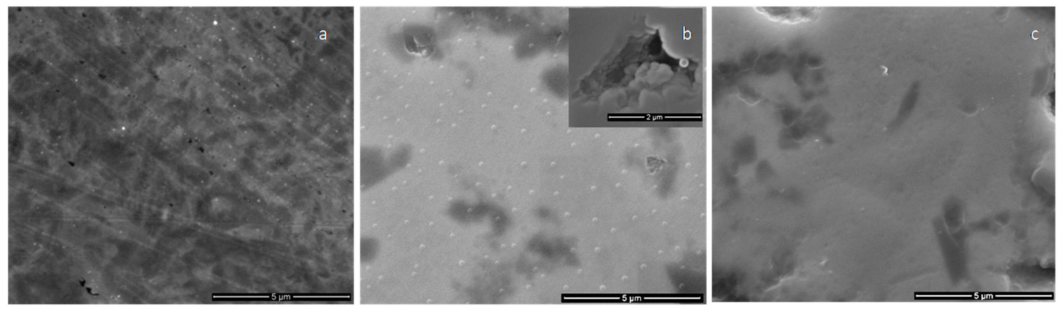
3.3. SEM and EDS Analysis of Calcium Phosphate Coatings

3.3.1. Morphological Analysis of Calcium Phosphate Layers Obtained in Different Experimental Conditions

The surface morphologies of the calcium phosphate coatings deposited on polymeric and metallic substrates were investigated by scanning electron microscopy.
The calcium phosphate coatings obtained in magnetron sputtering discharges when the substrate holder is grounded, usually present columnar grains growth perpendicular to the substrate [1]. The equiaxed grain structure was reflected in the coating surface morphology.
In order to establish the influence of polymeric substrate heating (due to bombardment with the energetic atoms and radicals sputtered from the target/produced in the plasma) on the coating surface morphology, Ti substrates with mirror-like surfaces as reference were used.
In Figure 6, the SEM images of the coatings obtained on metallic substrates in magnetron sputtering discharge (50 W rf power, 4 h deposition time with 10 min plasma on/10 min plasma off) are presented. Regular granular like structures are observed on the surface of the calcium phosphate coatings deposited on Ti substrates for the Ar gas working pressure of 1.2 × 10⁻² mbarr (Figure 6b). In holes identified on the surface coatings (detailed from Figure 6b), mainly due to the Ti roughness, the granular structure of the layer growth was evidenced. In the case of CaP coatings generated at the 4.6 × 10⁻³ mbarr pressure, these structures were not revealed (Figure 6c). The compact morphology of the film (Figure 6c) can be due to the bombardment of the growing layer with more energetic particles during the deposition process. As it is known [17] in rf plasmas, the energy of the species coming from the plasma to the substrate increases as the pressure decreases.
Polymeric samples with thickness of about 1 mm and 200 µm has been used in order to analyze the influence of the substrate heating on the coating morphology. In the case of the polymeric substrates with 1 mm thickness (Figure 7b,c) the granular-like structure of the CaP layers are observed for both Ar gas working pressure. The patterning of the substrate due to heating seems to be more pronounced for the 4.6 × 10⁻³ mbarr Ar gas working pressure than for 1.2 × 10⁻² mbarr. It seems that the creasing of the substrate favors the granular-like structure growth of the coating. The layers are not cracked or exfoliated and are grown on all the wrinkles of the polymeric substrates.
The surface features of the CaP coatings deposited on the polyprophylene samples with thicknesses of about 200 µm are showed in Figure 7e,f. A slight patterning of the polymeric substrate is visible in the case of films obtained in the rf magnetron discharge for the Ar gas pressure of 1.2 × 10⁻² mbarr (Figure 7e). The granular-like structure of the layers generated at Ar gas pressure of 4.6 × 10⁻³ mbarr is presented in Figure 7f.
The pattering of the polymeric substrates obtained in a thermally controlled manner in magnetron plasma discharge (by alternating 10 min of plasma on with 10 min of plasma off the temperature at the substrate do not exceed 100 °C) could be useful for the increasing of the adherence of the coating to the substrate. The deposited layers from Figure 7b,c,e, and f seem to be embedded in the polymers, as their granular structures are observed on the entire surface of the thermally patterned substrates.
For the 50 W rf power and continuous 4-h plasma exposure with no pauses, in both Ar gas working pressures, the layers were cracked, (Figure 8), due to the overheating of the substrates. The layers’ cracking could be avoided only alternating the deposition time duration with pauses.
An elemental analysis of the coatings deposited on Ti and polyprophylene substrates has been performed by electron dispersive spectroscopy (EDS).
The EDS spectrum of a CaP layer is presented in Figure 9. It ascertains the presence of Ca, O, P elements in the layer for both Ar gas working pressures. The Ca/P atomic ratio was determined from EDS quantification measurements to vary from 1.3 to 1.4 as the Ar gas working pressure decreases from 1.2 × 10⁻² to 4.6 × 10⁻³ mbarr. The decrease of Ca/P ratio as Ar pressure increases was also reported in [9] for CaP coatings deposited on polyethylene substrates. It was explained considering the negative charging of the substrate during the deposition process and further P removal from the coating, due to the bombardment with negatively charged oxygen ions ejected from the target. The species ejected from the target or those produced in the plasma bombarded the substrate and the coating, causing the resputtering of certain elements. The degree of surface charging of the polymers can determine the increase or the decrease of the bombardment with charged particles [9].

3.3.2. SEM Analysis of Coatings Adhesion by Tape Test

The adhesion of CaP coatings on the Ti and polyprophylene substrates was qualitatively estimated after the pealing of the coatings using an adhesive tape with the peel adhesion of 7.5 N/cm. The SEM images presented in Figure 10 reveal a better adhesion to the substrate in the case of CaP layers deposited on Ti substrate at the 1.2 × 10⁻² mbarr pressure (Figure 10a) in comparison with those obtained at 4.6 × 10⁻³ mbarr (Figure 10b). In the case of CaP films deposited on polyprophylene, a slightly delamination of the coatings was observed (Figure 10c,d). It is possible that the substrate thermal pattering assures a good adherence of the coatings to the substrate.

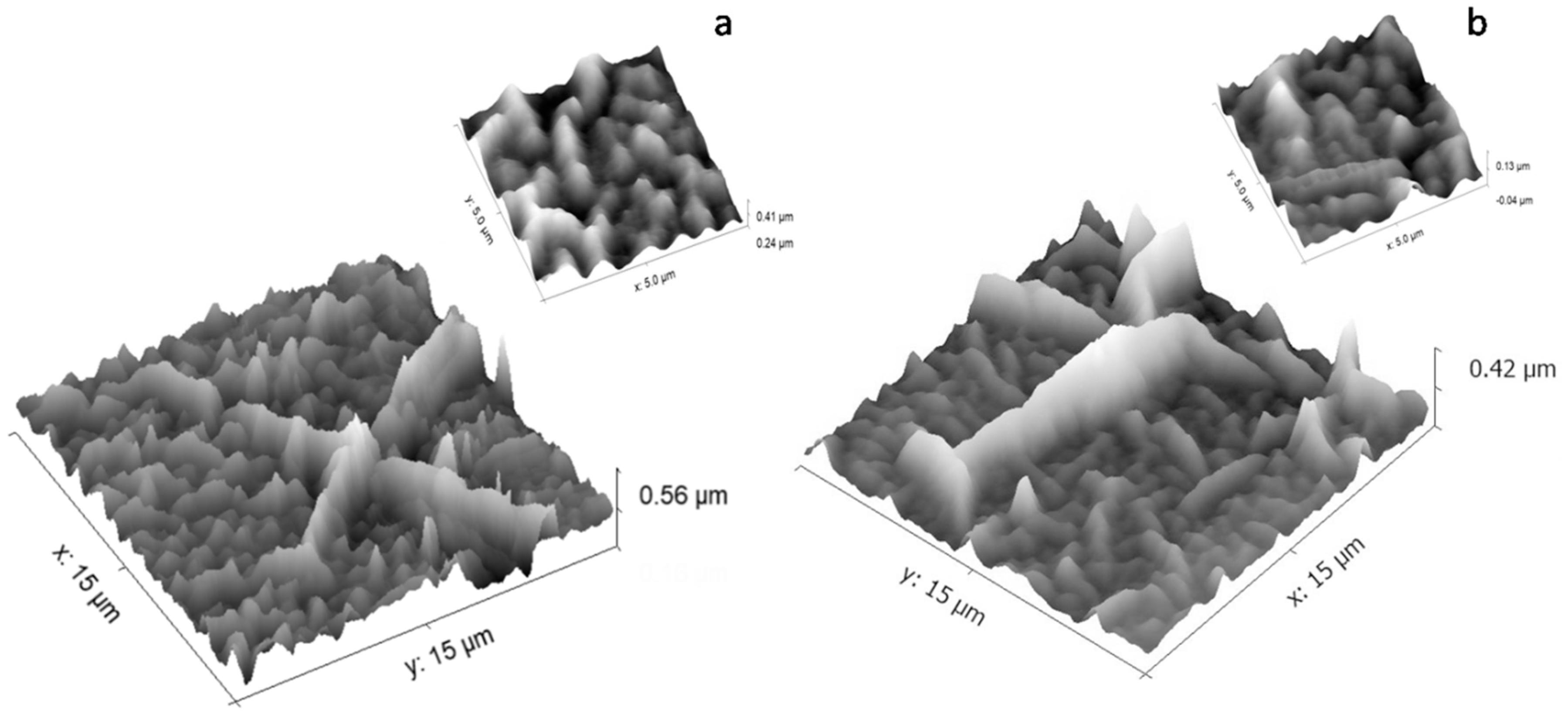
3.4. AFM Analysis of Calcium Phosphate Coatings

The calcium phosphate layers deposited on both Ti and polyprophylene substrates in magnetron sputtering discharge were investigated by AFM to reveal the influence of the thermal patterning of the 1 mm thickness polymer substrate to the surface coatings topography.
The coating topographies deposited on Ti substrates with mirror-like surface (Figure 11) are of grain like structure type. The sizes of the granular structures decrease as the pressure of the Ar gas working pressure decreases.
The thermal pattering of polymer substrates during the plasma deposition process influences the morphology of the CaP coatings, as can be observed in Figure 12 for both Ar gas working pressures. It is hard to see the granular structure of the coating, due to the polymer wrinkles. It is possible to indicate the embedding of CaP into the polymer. In the captions of Figure 12a,b (which represent AFM high resolution images of the coatings) the sizes of the smooth wrinkles are similar.

3.5. Roughness Measurements

The topography of the plasma-deposited layers influences it roughness. In Table 2 the roughness parameters of calcium phosphate layers generated on both polymeric and metallic substrates in comparison with the same measured values for the substrates are presented. The contribution of the granular structures of the deposited films to the roughness values was evidenced by using the mirror-like surfaces of the Ti substrates, which have a high resistance to heating. Thus, it can be observed that the roughness parameters of the coatings deposited on Ti substrates at low pressure (p = 4.6 × 10⁻³ mbarr) have the lowest value (Ra = 30 nm) relative to the roughness of the coatings deposited on polymeric substrates (Ra = 120 nm) in the same experimental conditions. The thermal patterning of the polymer during the deposition process is more pronounced at low pressures, as the SEM analysis showed. Previously, the authors of Reference [15] reported that the deposition of CaP thin films on polymeric materials (polylactic acids) in rf magnetron discharges conduce to different substrate patterning as a function of the treatment time.

4. Conclusions

In this paper, the results regarding the generation of CaP layers on polyprophylene in magnetron sputtering discharge for 4 h deposition times, in a 10 min plasma on/10 min plasma off scheme, to avoid the overheating of the substrates, are presented. During the deposition time, the temperature at the substrate did not exeed 100 °C.
A low deposition rate with minimum plasma temporal fluctuations were chosen to be suitable for the formation of CaP layers on thermal sensitive polymer substrates, as the plasma components are similar in different gas working pressures and rf applied powers. The atomic and molecular ions from the magnetron sputtering plasma involved in the growth mechanism of the calcium phosphate layers were identified by mass spectrometry.
The features of the molecular absorbtion bands of the calcium phosphate coatings generated on polyprophylene substrates were revealed by FTIR spectroscopy. The Ca/P atomic ratio varied between 1.3 and 1.4, as the Ar gas working pressure decreased from 1.2 × 10⁻² mbarr to 4.6 × 10⁻³ mbarr.
The thermal patterning of the polymeric substrates during the deposition process influenced the morphology of the CaP coating surfaces and their roughness. CaP layers with higher roughness were obtained at 4.6 × 10⁻³ mbarr Ar gas working pressure and 50 W rf power as the polymers wrinkling was more pronounced. Major differences in the coatings’ peeling regions, as the result of the adhesion tests performed using a referenced adhesion tape, were not observed.

Author Contributions

Conceptualization A.G.; investigation D.B.D, M.G., A.G.; data analysis A.G., D.B.D., M.G.; validation: A.G., D.B.D., M.G.; writing—original draft preparation A.G., D.B.D., M.G.; writing—review and editing A.G., D.B.D., M.G.

Funding

This research was funded by the Romanian Ministry of Research and Innovation within the NUCLEU project PN 19 15 01 01/2019.

Acknowledgments

This research was supported by the Romanian Ministry of Research and Innovation within the NUCLEU project PN 19 15 01 01/2019. We thank Adrian Kiss and Petronela Scripca from the National Institute of Optoelectronics 2000, Magurele, Romania, for the roughness measurements of calcium phosphate coatings.

Conflicts of Interest

The authors declare no conflict of interest. The funders had no role in the design of the study; in the collection, analyses, or interpretation of data; in the writing of the manuscript, or in the decision to publish the results.

References

  1. Surmenev, R.; Vladescu, A.; Surmeneva, M.; Ivanova, A.; Braic, M.; Grubova, I.; Cotrut, C.M. Radio Frequency Magnetron Sputter Deposition as a Tool for Surface Modification of Medical Implants. In Modern Technologies for Creating the Thin-Film Systems and Coatings; Nikitenkov, N., Ed.; InTech: Vienna, Austria, 2017; pp. 1–36. [Google Scholar]
  2. Teh, S.J.; Lai, C.W. Carbon nanotubes for dental implants. In Applications of Nanocomposite Materials in Dentistry; Elsevier: Amsterdam, The Netherlands, 2018; pp. 93–105. [Google Scholar]
  3. Surmenev, R.A.; Surmeneva, M.A.; Grubova, I.Y.; Chernozem, R.V.; Krause, B.; Baumbach, T.; Epple, M. RF magnetron sputtering of a hydroxyapatite target: A comparison study on polytetrafluorethylene and titanium substrates. Appl. Surf. Sci. 2017, 414, 335–344. [Google Scholar] [CrossRef]
  4. Hulshoff, J.E.G.; Van Dijk, K.; van Der Waerden, J.P.C.M.; Wolke, J.G.C.; Ginsel, L.A.; Jansen, J.A. Biological evaluation of the effect of magnetron sputtered CaP coatings on osteoblast-like cells in vitro. J. Biomed. Mater. Res. 1995, 29, 967–975. [Google Scholar] [CrossRef] [PubMed]
  5. Goreninskii, S.I.; Bogomolova, N.N.; Malchikhina, A.I.; Golovkin, A.S.; Bolbasov, E.N.; Safronova, T.V.; Putlyaev, V.I.; Tverdokhlebov, S.I. Biological Effect of the Surface Modification of the Fibrous Poly(L-lactic acid) Scaffolds by Radio Frequency Magnetron Sputtering of Different Calcium-Phosphate Targets. Bionanoscience 2017, 7, 50–57. [Google Scholar] [CrossRef]
  6. Maitz, M.F. Applications of synthetic polymers in clinical medicine. Biosurf. Biotribol. 2015, 1, 161–176. [Google Scholar] [CrossRef] [Green Version]
  7. Vandijk, K.; Schaeken, H.; Wolke, J.; Jansen, J. Influence of annealing temperature on RF magnetron sputtered calcium phosphate coatings. Biomaterials 1996, 17, 405–410. [Google Scholar] [CrossRef]
  8. López, E.O.; Mello, A.; Sendão, H.; Costa, L.T.; Rossi, A.L.; Ospina, R.O.; Borghi, F.F.; Silva Filho, J.G.; Rossi, A.M. Growth of crystalline hydroxyapatite thin films at room temperature by tuning the energy of the RF-magnetron sputtering plasma. ACS Appl. Mater. Interfaces 2013, 5, 9435–9445. [Google Scholar] [CrossRef]
  9. Feddes, B.; Vredenberg, A.M.; Wolke, J.G.C.; Jansen, J.A. Bulk composition of rf magnetron sputter deposited calcium phosphate coatings on different substrates (polyethylene, polyterafluoroethylene, silicon). Surf. Coat. Technol. 2004, 185, 346–355. [Google Scholar] [CrossRef]
  10. Shapovalov, V.I.; Komlev, A.E.; Bondarenko, A.S.; Baykov, P.B.; Karzin, V.V. Substrate heating and cooling during magnetron sputtering of copper target. Phys. Lett. A 2016, 380, 882–885. [Google Scholar] [CrossRef]
  11. Feddes, B.; Wolke, J.G.C.; Weinhold, W.P.; Vredenberg, A.M.; Jansen, J.A. Adhesion of calcium phosphate coatings on polyethylene (PE), polystyrene (PS), poly(terafluoroethylene) (PTFE), poly(dimethylsiloxane) (PDMS) and poly-L-lactic acid (PLLA). J. Adhes. Sci. Technol. 2004, 18, 655–672. [Google Scholar] [CrossRef]
  12. Popa, C.L.; Groza, A.; Chapon, P.; Ciobanu, C.S.; Ghita, R.V.; Trusca, R.; Predoi, D. Physicochemical analysis of the polydimethylsiloxane interlayer influence on a hydroxyapatite doped with silver coating. J. Nanomater. 2015, 2015, 1–10. [Google Scholar] [CrossRef]
  13. Groza, A.; Ciobanu, C.S.; Popa, C.L.; Iconaru, S.L.; Chapon, P.; Luculescu, C.; Ganciu, M.; Predoi, D. Structural Properties and Antifungal Activity against Candida albicans Biofilm of Different Composite Layers Based on Ag/Zn Doped Hydroxyapatite-Polydimethylsiloxanes. Polymers 2016, 8, 131. [Google Scholar] [CrossRef] [PubMed]
  14. Ciobanu, C.S.; Groza, A.; Iconaru, S.L.; Popa, C.L.; Chapon, P.; Chifiriuc, M.C.; Hristu, R.; Stanciu, G.A.; Negrila, C.C.; Ghita, R.V.; et al. Antimicrobial activity evaluation on silver doped hydroxyapatite/polydimethylsiloxane composite layer. BioMed Res. Int. 2015, 2015, 1–13. [Google Scholar] [CrossRef] [PubMed]
  15. Tverdokhlebov, S.I.; Bolbasov, E.N.; Shesterikov, E.V.; Antonova, L.V.; Golovkin, A.S.; Matveeva, V.G.; Petlin, D.G.; Anissimov, Y.G. Modification of polylactic acid surface using RF plasma discharge with sputter deposition of a hydroxyapatite target for increased biocompatilility. Appl. Surf. Sci. 2015, 329, 32–39. [Google Scholar] [CrossRef]
  16. ASTM D3359-09, Standard Test Methods for Measuring Adhesion by Tape Test, ASTM International, West Conshohocken, PA. 2009. Available online: https://www.astm.org/DATABASE.CART/HISTORICAL/D3359-09.htm (accessed on 29 October 2019).
  17. Surmenev, R.A.; Surmeneva, M.A.; Evdokimov, K.E.; Pichugin, V.F.; Peitsch, T.; Epple, M. The influence of the deposition parameters on the properties of an rf-magnetron-deposited nanostructured calcium phosphate coating and a possible growth mechanism. Surf. Coat. Technol. 2011, 205, 3600–3606. [Google Scholar] [CrossRef]
  18. Haichuan, L.; Hyun, J.Y.; Kristina, H. Characterization of Phosphate-Containing Metabolites by Calcium Adduction and Electron Capture Dissociation. J. Am. Soc. Mass Spectrom. 2008, 19, 799–808. [Google Scholar]
  19. Ghumman, C.A.A.; Moutinho, A.M.C.; Santos, A.; Tolstogouzov, A.; Teodoro, O.M.N.D. TOF-SIMS VG Ionex IX23LS: Upgrade and application for the urinary stones analysis. Surf. Interface Anal. 2013, 45, 532–536. [Google Scholar] [CrossRef]
  20. Ghumman, C.A.A.; Moutinho, A.M.C.; Santos, A.; Teodoro, O.M.N.D.; Tolstogouzov, A. An upgraded TOF-SIMS VG Ionex IX23LS: Study on the negative secondary ion emission of III-V compound semiconductors with prior neutral cesium deposition. Appl. Surf. Sci. 2012, 258, 2490–2497. [Google Scholar] [CrossRef]
  21. Ghumman, C.A.A.; Moutinho, A.M.C.; Santos, A.; Tolstogouzov, A.; Teodoro, O.M.N.D. TOF-SIMS study of cystine and cholesterol stones. J. Mass Spectrom. 2012, 47, 547–551. [Google Scholar] [CrossRef]
  22. Ghumman, C.A.A.; Moutinho, A.M.C.; Tolstogouzov, A.; Teodoro, O.M.N.D. Time-of-flight secondary ion mass spectrometric identification of calcium formate Ca(HCO2)2 and metabolite of vitamin B6 in human stones. Rapid Commun. Mass Spectrom. 2011, 25, 997–999. [Google Scholar] [CrossRef]
  23. Ghumman, C.A.A.; Carreira, O.M.T.; Moutinho, A.M.C.; Tolstogouzov, A.; Vassilenko, V.; Teodoro, O.M.N.D. Identification of human calculi with time-of-flight secondary ion mass spectrometry. Rapid Commun. Mass Spectrom. 2010, 24, 185–190. [Google Scholar] [CrossRef]
  24. Melissa, R.J.; Horgen, F.D.; Orski, S.V.; Rodriguez, V.C.; BeersK, L.; Balazs, G.H.; Jones, T.T.; WorkT, M.; BrignacK, C.; Royer, S.J.; et al. Validation of ATR FT-IR to identify polymers of plastic marine debris, including those ingested by marine organisms. Mar. Pollut. Bull. 2018, 127, 704–716. [Google Scholar]
  25. Berzina-Cimdina, L.; Borodajenko, N. Research of Calcium Phosphates Using Fourier Transform Infrared Spectroscopy. In Infrared Spectroscopy-Materials Science, Engineering and Technology; Theophile, T., Ed.; InTech: Vienna, Austria, 2012. [Google Scholar] [Green Version]
Figure 1. Experimental set-up.
Coatings 09 00709 g001
Figure 2. Dependence of the deposition rate on the rf power averaged on 600 s.
Coatings 09 00709 g002
Figure 3. Temporal evolution of the calcium phosphate deposition rate (Å/s) for: (a) 50 W (0.13 Å/s mean value) and (b) 120 W rf power (0.41 Å/s mean value); at p = 1.2 × 10⁻² mbarr. The deviation is about 0.01 Å/s for 50 W and 0.1 Å/s for 120 W.
Coatings 09 00709 g003
Figure 4. Mass spectrum of the gas extracted from the magnetron plasma discharge.
Coatings 09 00709 g004
Figure 5. FTIR spectra of: (a) polypropylene substrate; (b) CaP sputtering target; (c) CaP coating on polymer substrate for 50 W rf power and 4.6 × 10⁻³ mbarr Ar gas working pressure; (d) CaP coating on polymer substrate for 50 W rf power and 1.2 × 10⁻² mbarr Ar gas working pressure.
Coatings 09 00709 g005
Figure 6. SEM images of: (a) Ti substrate; and of the calcium phosphate coatings generated on Ti substrate at: (b) p = 1.2 × 10⁻² mbarr; and (c) p = 4.6 × 10⁻³ mbarr; Ar gas working pressures.
Coatings 09 00709 g006
Figure 7. SEM images of: (a) 1 mm thickness polymer substrate; and CaP coatings generated on 1 mm thickness polymeric substrates at: (b) p = 1.2 × 10⁻² mbarr; and (c) p = 4.6 × 10⁻³ mbarr; Ar gas working pressure; (d) 200 µm thickness polymer substrates; and CaP coatings generated on 200 µm polymeric substrates at: (e) p = 1.2 × 10⁻² mbarr; and (f) p = 4.6 × 10⁻³ mbarr; Ar gas working pressure.
Coatings 09 00709 g007
Figure 8. SEM image of: (a) polymer substrate; (b) calcium phosphate coating generated in a continuously single run in magnetron sputtering discharge for 2 h with no pauses.
Coatings 09 00709 g008
Figure 9. EDS spectrum of calcium phosphate coating obtained at 50 W and 4.6 × 10⁻³ mbarr Ar gas working pressure.
Coatings 09 00709 g009
Figure 10. Tape tests for calcium phosphate coatings deposited on Ti substrates at (a) p = 1.2 × 10⁻² mbarr; (b) p = 4.6 × 10⁻³ mbarr; and on polyprophylene substrates at: (c) p = 1.2 × 10⁻² mbarr; (d) p = 4.6 × 10⁻³ mbarr.
Coatings 09 00709 g010
Figure 11. The calcium phosphate layers deposited on Ti substrate at: (a) 1.2 × 10⁻² mbarr; and (b) 4.6 × 10⁻³ mbarr; Ar gas working pressure.
Coatings 09 00709 g011
Figure 12. The calcium phosphate layers deposited on polypropylene at: (a) p = 1.2 × 10⁻² mbarr; and (b) p = 4.6 × 10⁻³ mbarr; Ar gas working pressure.
Coatings 09 00709 g012
Table 1. IR band assignment of polypropylene substrate [24], CaP sputtering target [25], and CaP coatings [12,13,14] on polymer substrates.
Polymer Substrate IR Band WavenumberIR Band AssignmentCaP Target IR Band WavenumberIR Band AssignmentCaP Layer IR Band WavenumberIR Band Assignment
2955, 2921, 2872, 2834C–H stretch3270O–H vibrations3450O–H vibrations
1454CH2 bend1090, 1010, 960vibrations in [PO4]3−2955, 2921, 2845C–H stretch
1375CH3 bend630OH vibrations1454CH2 bend
1165CH bend/CH3 rock/C–C stretch600, 560vibrations in [PO4]3−1375CH3 bend
997CH3 rock/CH3 bend/CH bend 1165CH bend/CH3 rock/C–C stretch
972CH3 rock/C–C stretch 1090, 1030, 940vibrations in [PO4]3-
897C–H vibrations 997CH3 rock/CH3 bend/CH bend
840CH2 rock/ C–CH3 stretch 972CH3 rock/C–C stretch
808CH2 rock/ C–C stretch/ C–CH stretch 897C–H vibrations
721C–H out of plane bend 840CH2 rock/ C–CH3 stretch
808CH2 rock/ C–C stretch/ C–CH stretch
721C–H out of plane bend
603, 570vibrations in [PO4]3−
Table 2. Roughness measurements of the substrates and CaP coatings.
Analyzed SampleRaRzRq
Ti substrate5 nm40 nm6 nm
polyprophylene substrate8 nm40 nm10 nm
calcium phosphate coating deposited on Ti substrate at p = 1.2 10−2 mbarr, P = 50 W50 nm150 nm20 nm
calcium phosphate coating deposited on Ti substrate at p = 4.6 10−3 mbarr, P = 50 W30 nm130 nm35 nm
calcium phosphate coating deposited on polyprophylene substrate at p = 1.2 10−2 mbarr, P = 50 W90 nm300nm130 nm
calcium phosphate coating deposited on polyprophylene substrate at p = 4.6 10−3 mbarr, P = 50 W120 nm500 nm140 nm

