Article

Analysis of the Surface/Interface Damage Evolution Behavior of a Coating–Substrate System under Heavy-Load Elastohydrodynamic Lubrication

1
College of Engineering, Huazhong Agricultural University, Wuhan 430070, China
2
Key Laboratory of Agricultural Equipment in Mid-Lower Yangtze River, Ministry of Agriculture, Wuhan 430070, China
3
SAIC Volkswagen Automotive Co., Ltd., Shanghai 201805, China
4
State Key Laboratory of Mechanical Transmission, Chongqing University, Chongqing 400044, China
5
Chongqing Yangjiang Machine manufacture Co., Ltd., Chongqing 400000, China
*
Author to whom correspondence should be addressed.
Coatings 2019, 9(10), 642; https://doi.org/10.3390/coatings9100642
Submission received: 21 August 2019 / Revised: 24 September 2019 / Accepted: 27 September 2019 / Published: 3 October 2019

Abstract

:
Keeping a coating–substrate system undamaged during heavy-load elastohydrodynamic lubrication (EHL) conditions is challenging. To overcome this problem, an EHL model with a coated gear pair was built. Firstly, based on the full-system finite element method, the effect of the coating elastic modulus on the oil film pressure was obtained. Secondly, the failure mode was predicted after the stress analysis. Finally, the surface/interface damage evolution behavior of the coating–substrate system was analyzed visually by embedding cohesive zone elements. In the numerical calculation, stiffer coatings tended to increase the film pressure and secondary pressure spike, compared with more compliant coatings. As the coating stiffness decreased, the maximum equivalent stress in the system reduced, and its location tended to develop close to or at the substrate. The coating cracking and interfacial delamination were individually caused by the shear stress in the coating and shear stress on the interface, and both of them initiated in the region of the secondary pressure peak. The interfacial delamination increased the crack failure probability of coating and vice versa. Therefore, through analyzing the EHL model, the exact damage growth location and its evolution in the coated solids can be determined, and the failure mechanism can be comprehensively revealed.

1. Introduction

As an effective way to achieve excellent surface load carrying capacity, coating technology has been widely employed in the field of rolling–sliding contact industrial friction pairs which are under heavy-duty elastohydrodynamic lubrication (EHL) conditions [1], such as gears, bearings, cams, etc. [2,3]. It is particularly important to reveal the EHL mechanism of coated couples. On the other hand, there are two main failure modes of thin coatings in service: coating cracking and interfacial delamination. The lack of a method to analyze the failure behavior of the coating–substrate system under heavy-load EHL conditions is an urgent problem that needs to be solved.
In recent years, many scholars have studied the EHL tribological behavior of coating–substrate systems. Based on fast Fourier inverse transform or the finite element (FE) method, Liu et al. [4] carried out point contact EHL analysis for a coating–substrate system. Wang et al. [5] studied the effect of coating material parameters on the stress distribution of coated parts. Liu et al. [6] and Xiao et al. [7] analyzed the EHL problem of line contact in coated gear transmissions. Habchi [8] used the FE method combined with the solution of the Reynolds equation to solve the point contact EHL issue for coated solids. Alakhramsing et al. [9] investigated EHL characteristics of coating–substrate systems with finite line contact taking non-Newtonian fluid into account. Stahl et al. [10] acquired the friction reduction mechanism of diamond-like carbon (DLC)-coated gear pairs coupling it with the temperature field. From the aspect of coating–substrate failure under the normal or tangential load, previous studies mostly focused on nano-indentation or scratch characterization experiments combined with cohesive zone model (CZM) [11,12,13] or virtual crack closure technology (VCCT) [12] to study the law of coating cracking and interface debonding damages [14]. Lin et al. [15] used the FE method to predict the interfacial delamination of a multi-layered system under indentation loading at the macroscale with the cohesive zone being considered around the delamination or crack tips. The failure properties of a DLC/steel system were evaluated using a combined nano-indentation and CZM coupled FE approach [16]. Early in the development lifecycle, the authors performed the running-in test of the DLC-coated gears under the heavy-load EHL conditions. As with other hard coatings [14], DLC deposited via physical vapor deposition usually results in a columnar grain structure. To provide additional insight into the cracked and delaminated area induced by the gear meshing force, the corresponding gear sample was milled by a focused ion beam (FIB) to obtain a cross-sectional view. The microstructural image (Figure 1) was obtained by scanning electron microscopy (SEM). It can be seen that the cracks vertically extend through the thickness of the entire coating (intergranular sliding of columnar grains), as well as a typical feature of delaminated area on the interface. It means that a coating’s cracking often is often followed by interfacial delamination under meshing load.
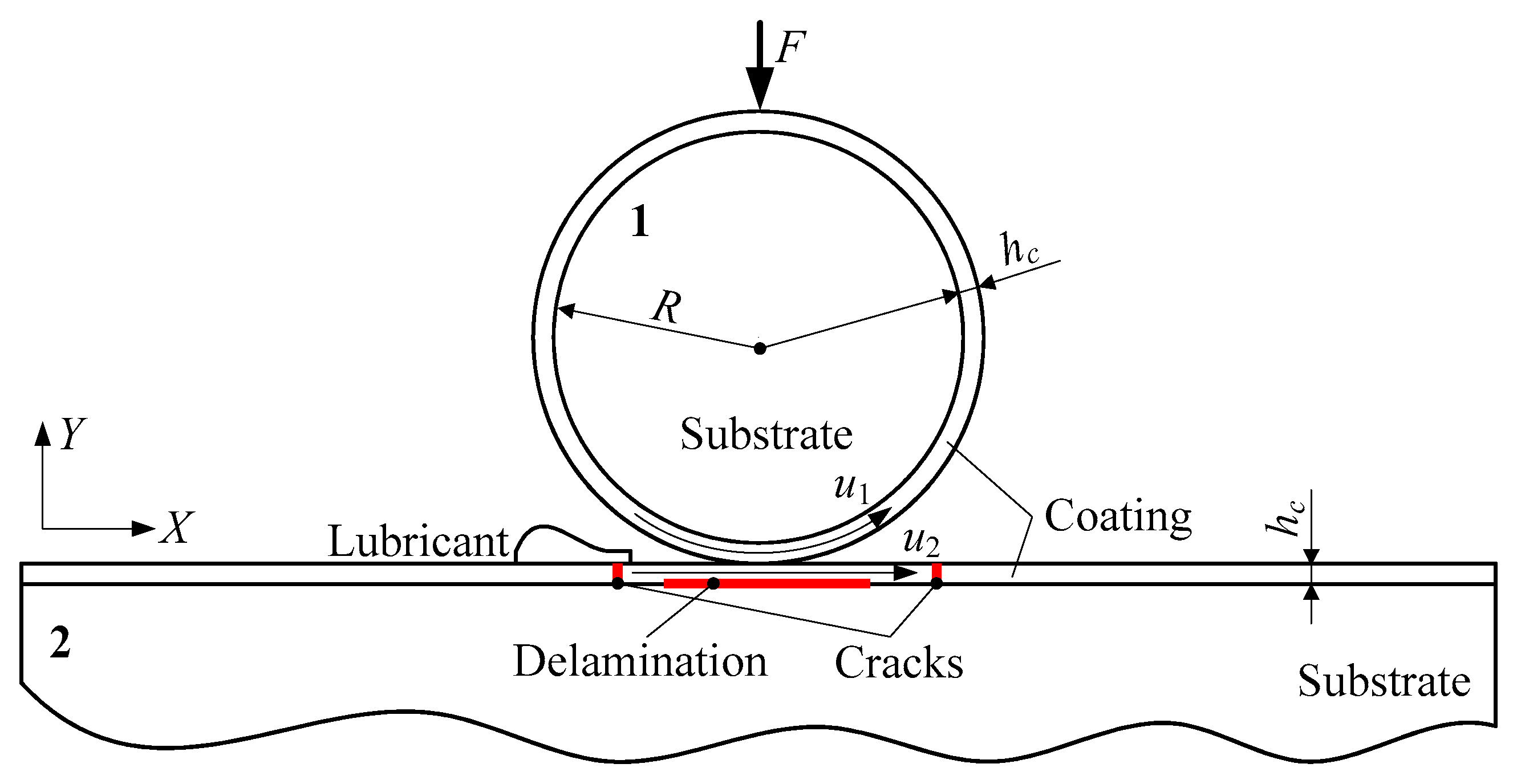
Previous studies on the damage evolution behavior of coating–substrate systems in heavy-load EHL service (Figure 2) are rare, and there are few studies that consider the interaction between coating cracking and interfacial delamination. Thus, these gaps were the focus of the this paper, and the above methods were the foundation for the present research. Among the above scholars, Habchi’s full-system FE method not only has an outstanding advantage in regards to solving speed, but can also establish a good interface for subsequent modelling of coating–substrate failure. Moreover, the cohesive zone model (CZM) was adopted because it has superiority in the following two aspects: 1) stress is a function of crack displacement in the failure process, which avoids the singularity of crack tip stress; and 2) there is no need for a pre-crack before calculation.
The main problem now is that when the CZM is coupled as fracture/damage behavior in the coating–substrate system, the non-linearity becomes stronger when solving the heavy-load EHL model. In the current paper, the full-system FE method combined with CZM was employed to analyze the complex mechanical problems involved in the surface contact and failure behavior of the coatings. The inverse analysis [17] of the coating–substrate can make up for the defect of the over-reliance on trial-and-error methods in the design of coatings, and can predict failures in the system in advance, which can reduce the selection time of coatings as well as save costs related to testing. Therefore, accurately obtained internal and interfacial stressors of the coated system, timely prediction of the failure of the coated components, and improvement of the surface load carrying capacity of the coated friction pairs creates a foundation for the application of the coating in the field of heavy-duty transmission. Furthermore, inverse analysis emphasizes the usefulness and significance of the FE model.

2. Numerical Model Description

2.1. EHL Model

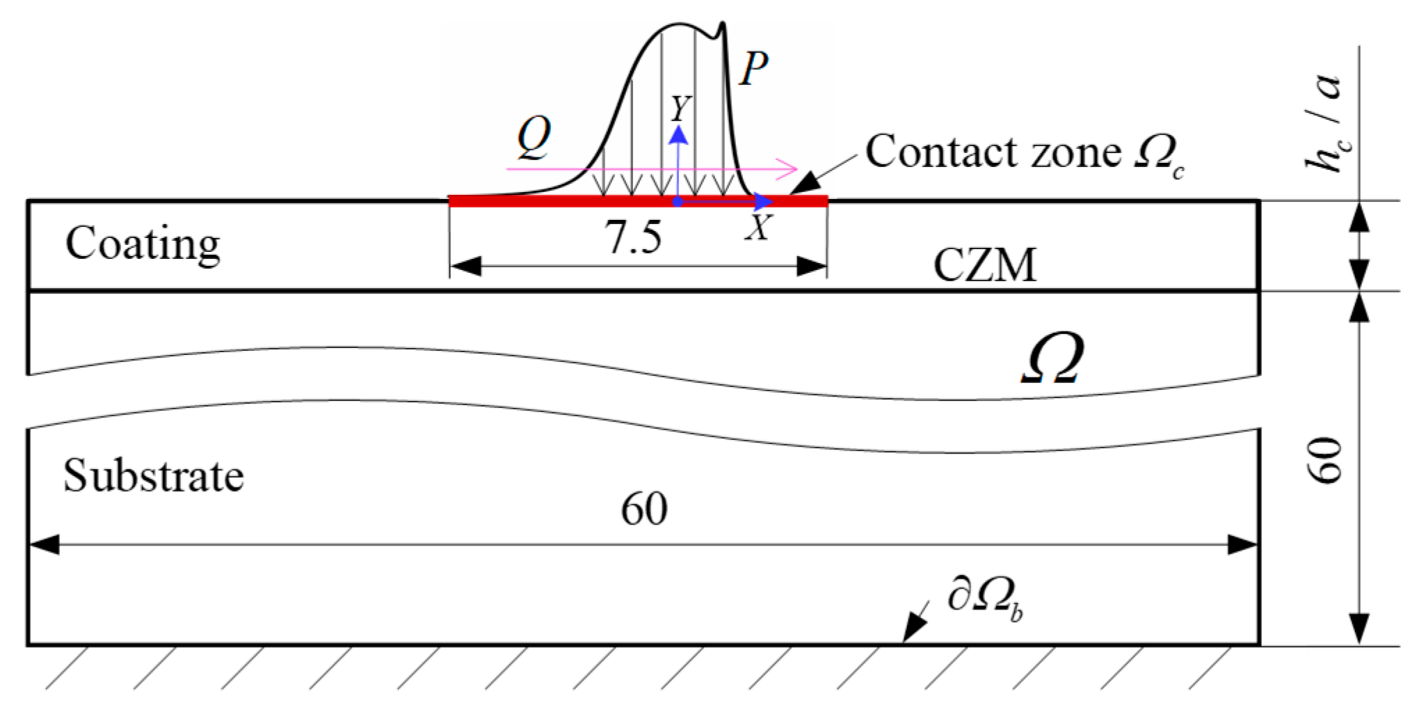
The computational domain of the numerical model is shown in Figure 3. The EHL problem is solved under the assumed plane strain condition. It is appropriate to define the range of two-dimensional calculation domain Ω as X [ 30 ,   30 ] and Y [ h c / a 60 ,   0 ] for solving elastic deformation from References [8,18]. On the other hand, to ensure that the oil film pressure at the inlet and outlet is 0, the calculation of the lubricant domain can be calculated on the one-dimensional contact area Ω c ( X [ 4.5 ,   3 ] ). The fixed-boundary condition is applied to the substrate base ( Ω b = 0 ).
In order to solve the generalized Reynolds and elastic equations in the EHL problem conveniently, the parameters of these equations are firstly dimensionless and treated as follows:
{ P = p p h ,   τ ¯ = τ p h ,   η ¯ = η η 0 ,   ρ ¯ = ρ ρ 0 X = x a ,   Y = y a U = u R a 2 ,   V = v R a 2 ,   H = h R a 2
where P , τ ¯ , η ¯ , ρ ¯ , X , Y , U , V , and H are dimensionless forms of the oil film pressure p , oil film shear stress τ , oil viscosity η , lubricant density ρ , x and y components of the coordinates, solid elastic deformation along x and y directions, and oil film thickness h , respectively. η 0 and ρ 0 individually correspond to the ambient viscosity and density of the lubricant. p h and a denote the maximum Hertzian contact pressure and half-width of uncoated solids, and are defined as below:
{ p h = 2 F π a a = 8 F R π Ε
where F is the external load. Two substrates are made of a same material, so the reduced elastic modulus of the contacting bodies Ε can be described by the following equation:
Ε = E s 1 ν s 2
where E s and ν s are the elastic modulus and Poisson’s ratio of the substrate, respectively.
Constitutive equation of non-Newtonian fluid lubricants is constructed by the Ree–Eyring model. The equivalent oil film viscosity η ¯ * is shown as:
η ¯ * = η ¯ ( τ τ 0 ) / sinh ( τ τ 0 )
where τ 0 is the Eyring characteristic shear stress.
The relationship between viscosity and pressure is described by the Roelands [19] viscosity–pressure equation:
η ¯ = exp { 1 + ( ln η 0 + 9.67 ) [ ( 1 + 5.1 × 1 0 9 P p h ) α 5.1 × 1 0 9 × ( ln η 0 + 9.67 ) ] }
where α is the Barus viscosity–pressure coefficient.
The density–pressure equation of Dowson–Higginson [20] is adopted:
ρ ¯ = 1 + 2.266 × 1 0 9 P p h 1 + 1.683 × 1 0 9 P p h
The dimensionless generalized Reynolds equation for calculating oil film pressure on Ω c is:
X ( ε ¯ P X ) { ρ ¯ H [ u 1 η ¯ e η ¯ e ( u 1 u 2 ) ] } X = 0
where ε ¯ = ρ ¯ H 3 λ ( 1 η ¯ e η ¯ e η ¯ e 2 ) , λ = R 2 η 0 p h a 3 , 1 η ¯ e = 0 1 1 η ¯ * d Y , 1 η ¯ e = 0 1 Y η ¯ * d Y , and 1 η ¯ e = 0 1 Y 2 η ¯ * d Y .
The boundary conditions of the Reynolds equation are shown as follows [21]:
{ P = 0 on   Ω   c   P 0 on   Ω   c P / X = 0 on   the   cavitation   boundary
Dimensionless oil film thickness H is expressed as:
H ( X ) = H 0 + X 2 2 V ( X )
where, H 0 is the approach distance of the rigid body, which is determined by the load balance equation:
Ω   c P ( X ) d Ω = π 2

2.2. Cohesive Zone Model

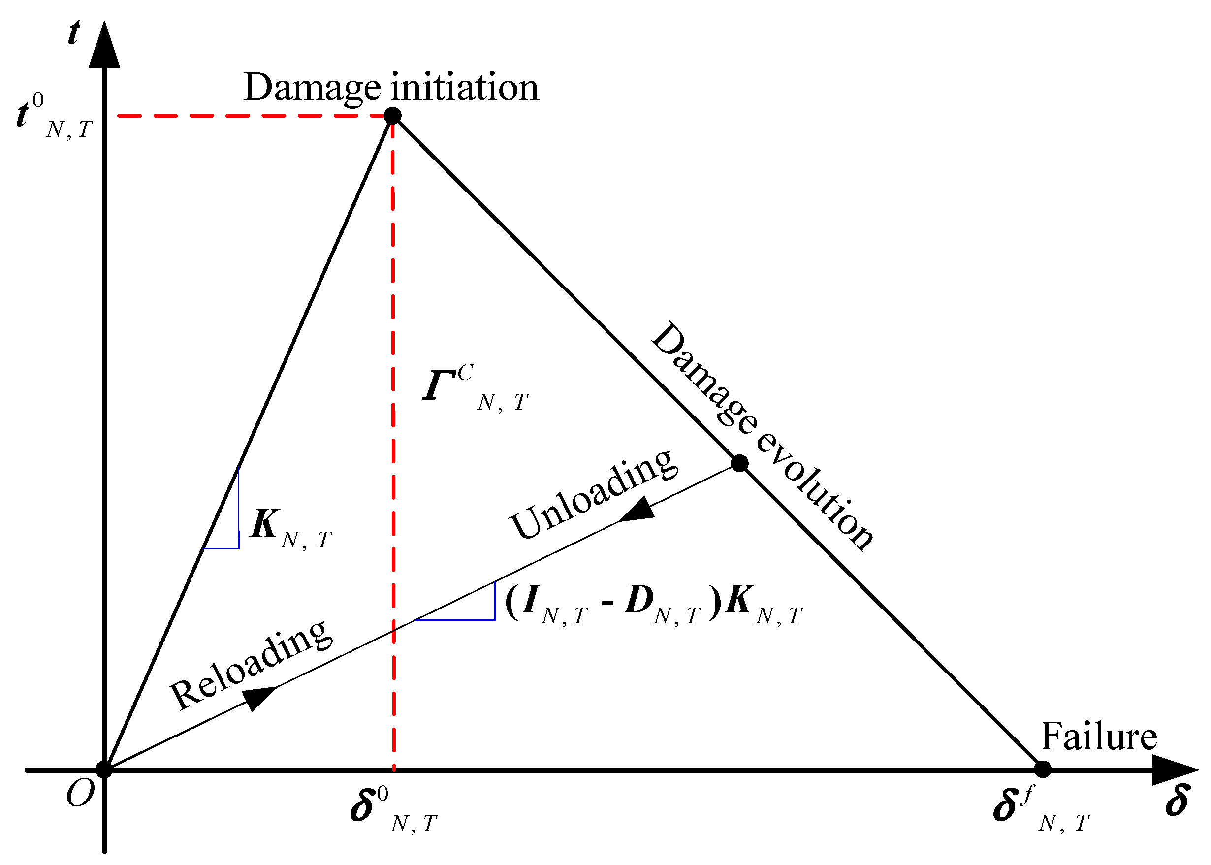
In this paper, the CZM (bilinear traction-separation law) [22] was adopted to simulate the surface/interface failure behavior. Although an advanced CZM with more accurate behavior in the shear direction was mentioned by previous researchers [23,24], the currently selected model is a simple and effective way to solve the problem. Figure 4 shows the CZM coupled with tensile and shear loads, and its constitutive equation can be expressed as:
t N , T = { K N , T δ N , T ( 1 D N , T ) K N , T δ N , T 0 δ N , T < δ N , T 0 δ N , T 0 δ N , T < δ N , T f δ N , T δ N , T f
where, t N , T is the separation traction stress. δ N , T is the separation traction displacement. δ N , T 0 is the critical displacement when damage occurs. δ N , T f is the displacement when the cohesive element fails completely. K N , T is the cohesive initial stiffness. D N , T is the cohesion cumulative damage stiffness (SDEG). When SDEG = 1, the cohesive element is completely invalid. The subscripts N and T in the parameters represent the normal and tangential directions, respectively.
Under mixed load, damage may occur when any stress component in normal or tangential directions reaches the limit value. Therefore, this paper selects the maximum nominal stress criterion to judge the failure:
< t N > = { t N ( t N 0 ) 0 ( t N < 0 )
where < t N > stands for Macaulay parentheses.
The damage criterion of power function is used to evolve the damage process of coating and interface under mixed load, which can be expressed as:
( Γ N Γ C N ) α + ( Γ T Γ C T ) α = 1
Where Γ N and Γ T are individually the work done by the normal and tangential forces in the process of damage. α is a power exponent. In this study, the power exponential α is defined as 1 [25,26,27], which is the most commonly used value and corresponds to a linear fracture criterion.

3. Numerical Calculation

The current paper takes the Forschungsstelle für Zahnräder und Getriebebau (FZG) standard gear pair (20CrMnTi) as the research object in the light of ISO 14635-1. Compared to the light load, the coating–substrate system is more likely to fail under heavy load. In addition, the solution to the Reynolds’ equation is known to be unstable in the central contact area for highly loaded contacts. To make the solution method universal, a load stage of 12th was selected, which stands for heavy load. The DLC coating commonly used in the gear industry was chosen. The coating was obtained by low temperature vapor deposition and its thickness was 2   μ m [28]. For a DLC coating, the great variety of its structures and sp3 content leads to a wide range of mechanical property. Detailed geometric parameters, material properties, operating conditions, and lubricant properties are shown in Table 1.
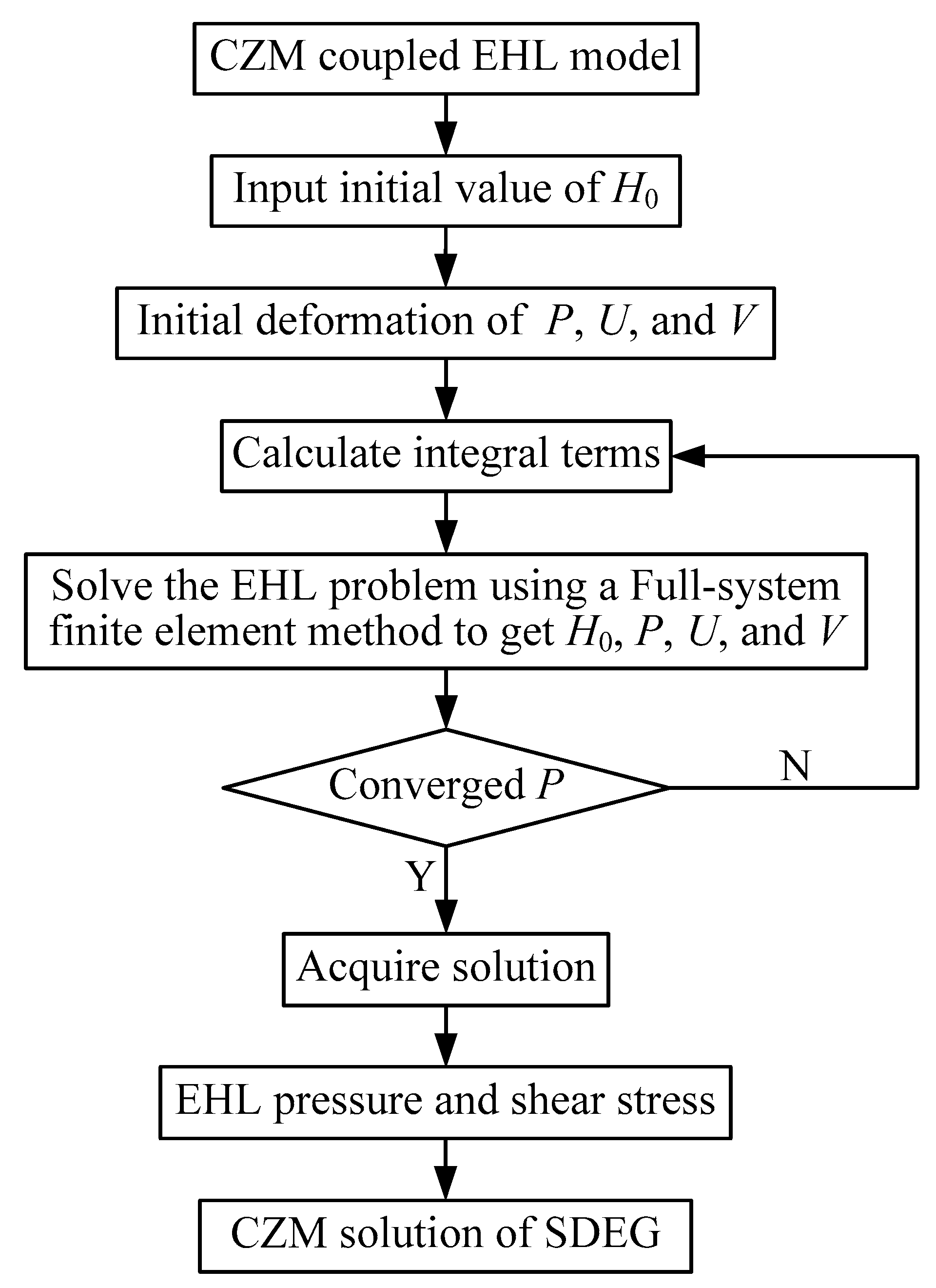
The global numerical solution scheme is shown in Figure 5. Based on the full-system FE method, all the equations to be solved are discretized under the steady-state calculation condition. The numerical calculation was carried out under given initial values H0, P, U, and V, and then the EHL equations of each time step were solved by direct FE and Newton–Raphson iterations to solve them. An implicit relationship was established between the fluid and solid domains and H0 was continuously updated through the form of full coupling. Lagrangian fifth-order and second-order elements were applied to the Reynolds and elasticity equations, respectively. The specific EHL solution method is described in Reference [21]. Then, the EHL pressure and shear stress were coupled into the coated system to obtain the surface/interface damage evolution. The residual stress in the thin coating is usually approximately −0.02 to −2 GPa. Although it may be a bit large in the coating, it has only a little effect on failure due to the compressive residual stress. On the other hand, the residual stress is arduous to simulate using the FE method, and it does not affect the fracture/damage law explored in this work. This means that it is reasonable to consider the ideal situation of the system (residual stress-free) when it comes to studying the problem of the failure mechanism. However, it should be emphasized that residual stress will be taken into account in further works for improvement, which can then obtain more accurate and realistic results.

4. Results and Discussion

4.1. EHL Response

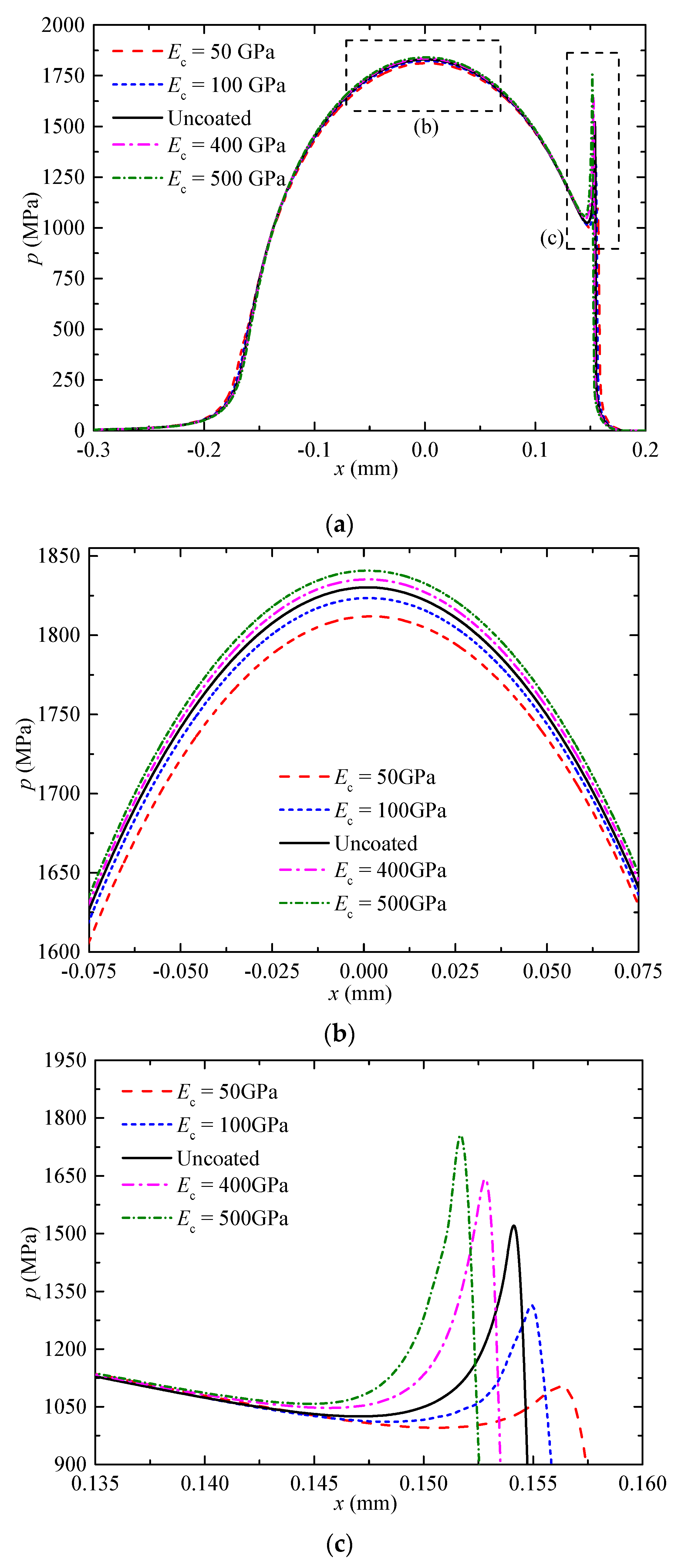
The full-system FE method was applied to analyze the line contact EHL model of coated solids, and the effect of coating elastic modulus on oil film pressure was studied. As shown in Figure 6, the calculated oil film pressure distribution curve conformed to the typical EHL characteristics. The lubricant was acting on the gear surface under the rolling–sliding contact. At a high contact pressure of 1841 MPa, the material deformed locally, and a parallel clearance was formed among the contact surfaces. Unlike Hertzian contact, there was a secondary peak pressure at the oil film outlet at the edge of the contact surface. On the whole, the five oil pressure curves basically coincided because of the thin coating, which means that its coating elastic modulus had little effect on the oil film pressure distribution. However, from the local magnification observation, with the increase in the coating elastic modulus (stiffness), the central pressure of the oil film increased, and the secondary pressure peak became more prominent. This conclusion is consistent with the results of the analysis of the uncoupled CZM on the interface. In order to predict the specific failure mode and location of the coating–substrate system, a stress analysis will be carried out during follow-up. Two typical cases were selected in order to analyze the subsequent damage evolution behavior of the system: 1) soft coating and hard substrate ( E c = 50   GPa ); and 2) hard coating and soft substrate ( E c = 500   GPa ).

4.2. Equivalent Stress Analysis

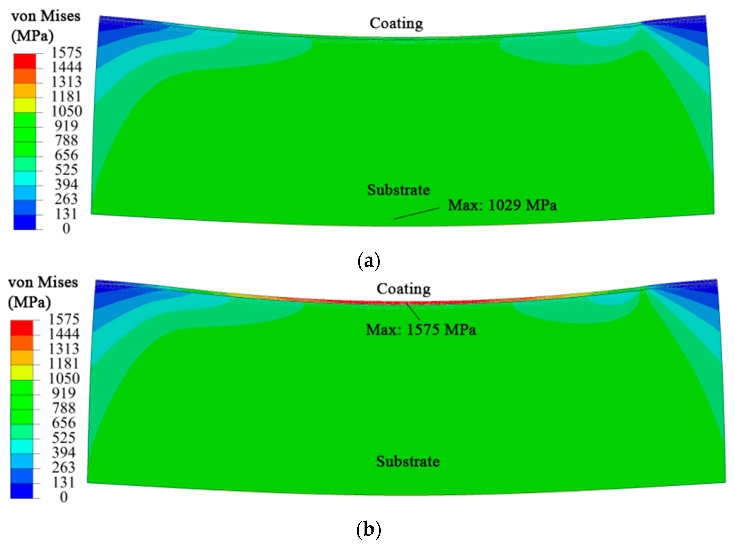
Coupling the above EHL pressure and shear stress into the failure model of the coated solids, the equivalent stress of the system was calculated first. Figure 7 shows the von Mises equivalent stress distribution nephogram. The smaller the coating elastic modulus, the smaller the stress that will cause certain elastic deformation in the coating. Obviously, under the same external load, the maximum equivalent stress of the soft coating (1029 MPa) was smaller than that of the hard coating (1575 MPa). On the other hand, for soft coatings, the maximum equivalent stress mainly distributed in the substrate (sub-surface). For hard coatings, the maximum equivalent stress mainly concentrated on the surface of the coatings and the interface between coatings and substrates, thus increasing the yield probability of these areas. In view of this reason, the subsequent failure analysis of the coating–substrate system was performed with a hard coating and a soft substrate as the focus of this paper. It can also be seen from the nephogram that the equivalent stress of the coated solid was larger at the contact edge (i.e. near the oil film outlet) due to the influence of the secondary pressure peak of the EHL. In addition, Wang et al. [5] showed that the harder coating would cause greater von Mises stress as well as stress differences between the upper and lower interfaces under the EHL point contact, which proved the correctness of the current numerical calculations.

4.3. Failure Prediction

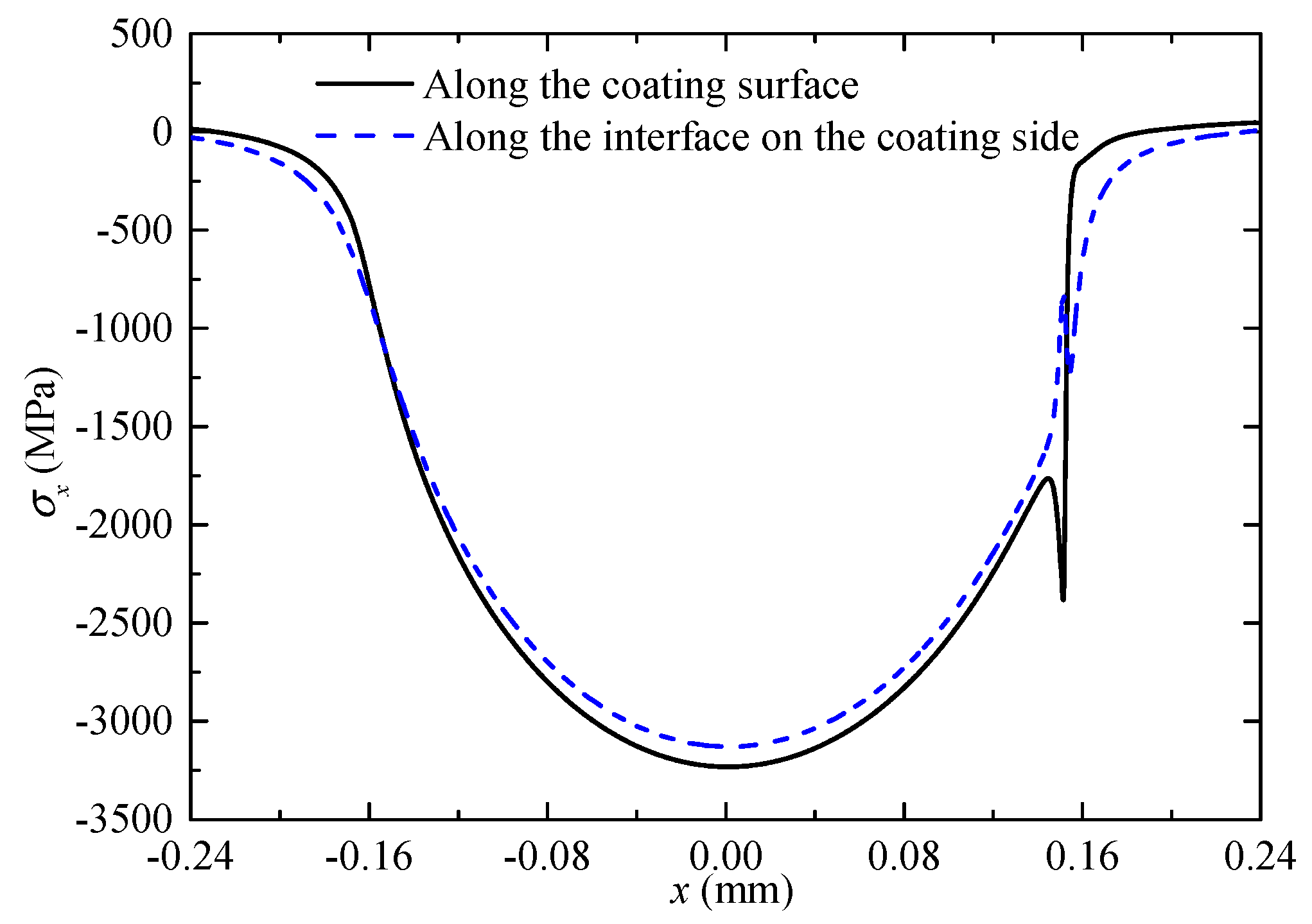
The coating and interfacial stress of ideal non-destructive coating–substrate system were analyzed, and the failure mode and location were predicted. Figure 8 shows the stress distribution along the x-direction, σ x , on the surface of the coating and the side near the interface. The tensile stress in the contact width region was small, mainly presenting as compressive stress. It was found that the maximum shear stress in the coating was much larger than the tensile stress, which distributed near the secondary pressure peak (x = 0.153 mm). Figure 9 shows the distribution of shear stress along the thickness direction in the coating. It appeared that the maximum shear stress was about 500 MPa at the position of 1.25 μm thickness of the coating. It can be seen that the crack of thin coating was mainly caused by the shear stress at the second pressure peak under the heavy-load EHL pressure, which shows the failure of mode II (sliding type).
Figure 10 shows the normal and tangential stress distribution curves of the interface under heavy-load EHL pressure. As mentioned above, the influence of compressive stress (negative value) on the system failure can be neglected. Compared with the normal stress at the interface, shear stress plays a dominant role in the delamination failure of the interface. Near the secondary pressure peak, the shear stress can reach 400 MPa, so the region is where the interfacial delamination initiation occurs. Like the coating cracking, it also shows mode II failure.

4.4. Damage Evolution

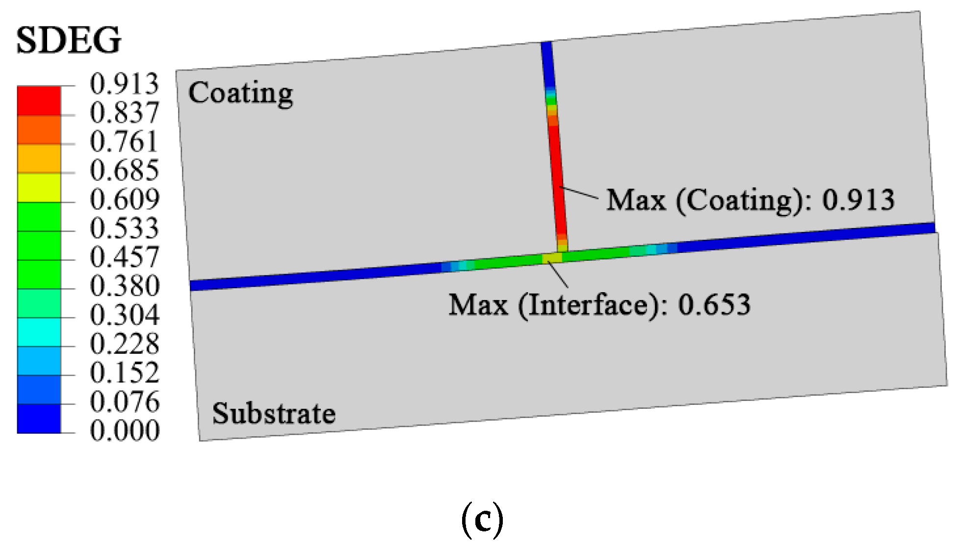
Firstly, the cohesive elements were implanted into the coating–substrate system to simulate the cracks (perpendicular to the coating, coordinate x = 0.153 mm) and interfacial delamination failure. Then, the EHL pressure and shear stress corresponding to hard coating and soft substrate were coupled into the system. Finally, the surface/interface damage evolution behavior was analyzed visually. Table 2 exhibits the main parameters of the CZM for the DLC coating and steel substrate. The failure parameters for coatings and interfaces are usually determined by an indentation test and pull-out tests, etc. According to the maximum failure stress (~500 MPa and ~400 MPa) in Figure 9 and Figure 10, to visualize the damage evolution behavior of the system, it was necessary to select the smaller stress values in Table 2. For coatings, it was assumed that 450 MPa (weak crack resistance) was required to be close to 500 MPa in order to accumulate crack damage. For the interface, 350 MPa (weak bonding capacity) was chosen.
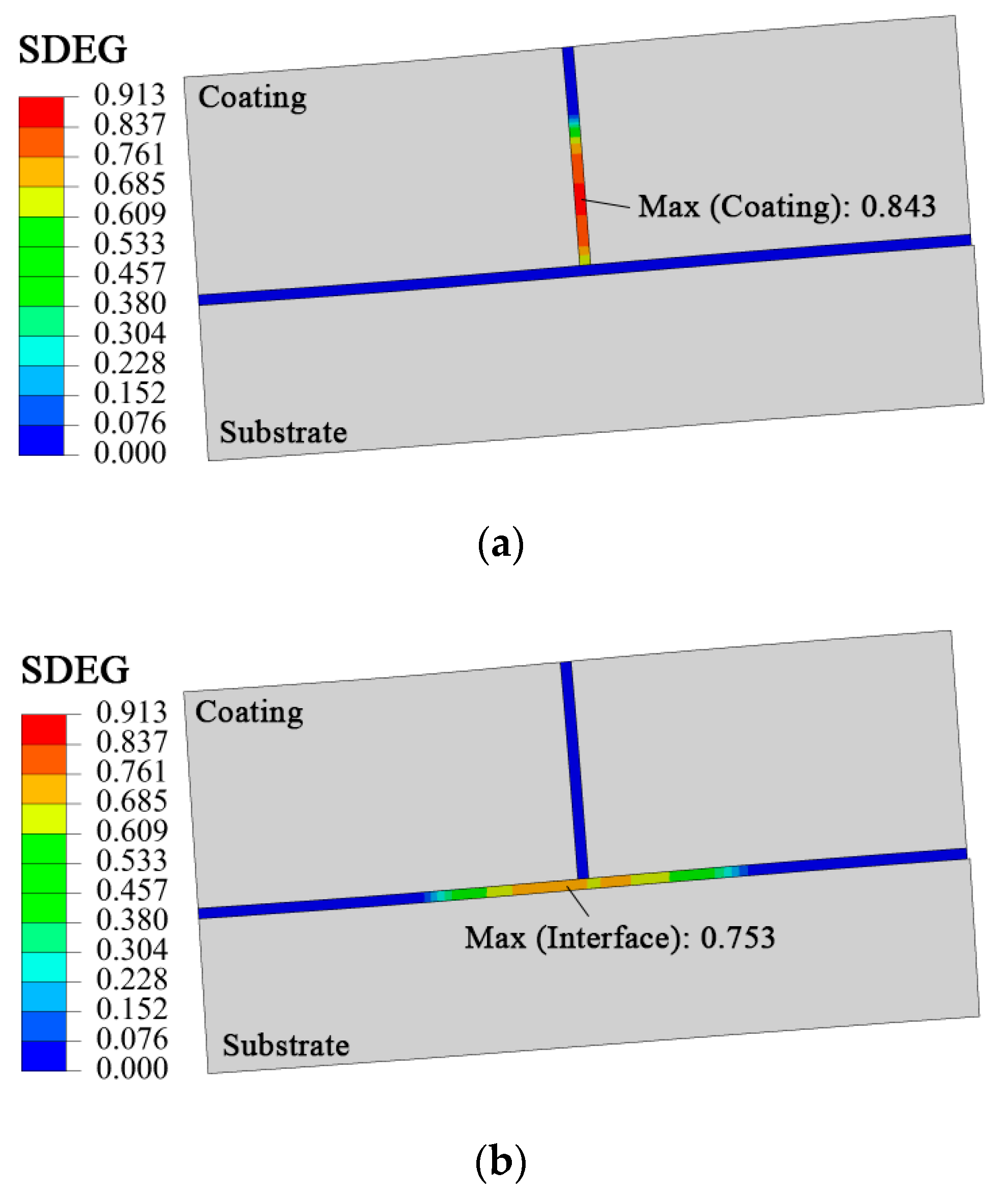
The calculated initiation and propagation behaviors of coating cracks and the interface are shown in Figure 11, which was evaluated by the cumulative damage stiffness of the CZM. The location of the maximum SDEG value of the coating and interface was observed, which was consistent with the failure prediction of the coating–substrate system by stress analysis in Section 4.3. Coating cracks and interfacial delamination initiated near the secondary pressure peak, and then propagated from the SDEG maximum region to the vicinity.
On the other hand, comparing Figure 11c with Figure 11a,b, it was found that the maximum cumulative damage stiffness of the coating crack increased (0.843→0.913) under the EHL pressure compared with the coating–substrate system with the ideal bonded interface. Compared with the ideal system without coating crack damage, the maximum cumulative damage stiffness of the system with crack decreases (0.753→0.653). It also means that if the interfacial delamination damage exists in the system beforehand, the probability of cracking in the coating increases. If the coating cracking occurs, the interfacial delamination damage will be weakened. This conclusion is consistent with the relationship between coating cracking and interfacial delamination damage studied by the indentation method in Reference [32]. It can be explained by the energy transfer theory: if the anti-crack ability of the coating is weak, the coating crack will consume more energy under the EHL pressure, which leads to the interface delamination consuming less energy. This means that the interfacial delamination increased the crack failure probability of coating, otherwise, the reverse. It confirms the reliability of the implanted cohesive elements for simulation evaluation of coating cracking and interfacial delamination.

5. Conclusions

This research investigated the surface/interface damage evolution behavior of a coating–substrate system under heavy-load EHL. The main findings from this study are listed below.
  • On the whole, when the load was constant, the elastic modulus of the thin coating (on the steel substrate) had little effect on the oil film pressure distribution. Locally, with the increase of the coating elastic modulus, the oil center pressure increased, and the secondary pressure peak became more significant due to the change in coating stiffness. This conclusion is consistent with the results of the analysis of the uncoupled CZM on interface.
  • Under the same external load, the maximum equivalent stress of the soft coating system was smaller than that of the hard coating system, which was located on the subsurface of the system, while the maximum equivalent stress of the hard coating system was distributed on the surface of the coating and the interface. This was because of the stiffness difference between the coating and substrate from the point of view of mechanics.
  • When the thin coating and steel gear substrate system was in service under heavy-load EHL, the shear stress in the coating and shear stress on the interface were the main causes of the coating cracking and interfacial delamination, respectively, which appeared near the secondary pressure peak and all show sliding type failure. The reason is that the geometric dimensions of the contact solids varied greatly, which resulted in shear stress in the dangerous section being much larger than the tensile stress.
  • The surface/interface damage evolution behavior of the coating–substrate system was analyzed visually by embedding cohesive zone elements. In light of the energy transfer theory, the interfacial delamination increased the crack failure probability of the coating and vice versa.

Author Contributions

Y.X. and W.S. conceived and designed the paper; M.Z. performed the experiments and analyzed the FIB/SEM figure; Y.X. and M.K. carried out the simulation work and analyzed the data. Y.X. and M.Z. wrote the paper.

Funding

The research was funded by the National Natural Science Foundation of China (No. 51905204), the Hubei Provincial Natural Science Foundation of China (No. 2018CFB227), and the Fundamental Research Funds for the Central Universities (No. 2662017QD003).

Acknowledgments

The authors would like to acknowledge the Southwest Institute of Physics (P.R. China) for the preparation of the coatings.

Conflicts of Interest

The authors declare no conflict of interest. The funders had no role in the design of the study; in the collection, analyses, or interpretation of data; in the writing of the manuscript, or in the decision to publish the results.

References

  1. Liu, H.; Liu, H.; Zhu, C.; Zhou, Y. A Review on Micropitting Studies of Steel Gears. Coatings 2019, 9, 42. [Google Scholar] [CrossRef]
  2. Hieke, A.; Lieberman, V.; van der Kolk, G.J. Hard Coatings and Coating Processes for the Automotive Industry. In Coating Technology for Vehicle Applications; Cha, S.C., Erdemir, A., Eds.; Springer International Publishing: Cham, Switzerland, 2015; pp. 133–148. [Google Scholar]
  3. Xiao, Y.; Shi, W.; Li, L.; Ye, X. Fatigue performance of cylindrical gearing with DLC coatings. In Proceedings of the International Gear Conference 2014, Lyon, France, 26–28 August 2014; Velex, P., Ed.; Chandos Publishing: Oxford, UK, 2014; pp. 516–522. [Google Scholar]
  4. Liu, Y.; Chen, W.W.; Zhu, D.; Liu, S.; Wang, Q.J. An Elastohydrodynamic Lubrication Model for Coated Surfaces in Point Contacts. J. Tribol. 2007, 129, 509–516. [Google Scholar] [CrossRef]
  5. Wang, Z.-J.; Wang, W.-Z.; Wang, H.; Hu, Y.-Z. Stress Analysis on Layered Materials in Point Elastohydrodynamic-Lubricated Contacts. Tribol. Lett. 2009, 35, 229–244. [Google Scholar] [CrossRef]
  6. Liu, H.; Zhu, C.; Wang, Z.; Xu, X.; Tang, J. Investigation on the effect of coating properties on lubrication of a coated spur gear pair. Proc. Inst. Mech. Eng. Part J J. Eng. Tribol. 2018, 232, 277–290. [Google Scholar] [CrossRef]
  7. Xiao, Y.; Shi, W.; Luo, J. Mechanical responses of coated solids in elastohydrodynamically lubricated line contacts. Int. J. Surf. Sci. Eng. 2017, 11, 450. [Google Scholar] [CrossRef]
  8. Habchi, W. A numerical model for the solution of thermal elastohydrodynamic lubrication in coated circular contacts. Tribol. Int. 2014, 73, 57–68. [Google Scholar] [CrossRef]
  9. Alakhramsing, S.S.; De Rooij, M.B.; Schipper, D.J.; Van Drogen, M. Elastohydrodynamic lubrication of coated finite line contacts. Proc. Inst. Mech. Eng. Part J J. Eng. Tribol. 2017, 232, 1077–1092. [Google Scholar] [CrossRef] [Green Version]
  10. Ziegltrum, A.; Lohner, T.; Stahl, K. TEHL Simulation on the Influence of Lubricants on the Frictional Losses of DLC Coated Gears. Lubricants 2018, 6, 17. [Google Scholar] [CrossRef]
  11. Lofaj, F.; Németh, D. Multiple cohesive cracking during nanoindentation in a hard W-C coating/steel substrate system by FEM. J. Eur. Ceram. Soc. 2017, 37, 4379–4388. [Google Scholar] [CrossRef]
  12. Lee, C.-C. Overview of interfacial fracture energy predictions for stacked thin films using a four-point bending framework. Surf. Coat. Technol. 2013, 237, 333–340. [Google Scholar] [CrossRef]
  13. Hu, J.; Chou, Y.; Thompson, R. Cohesive zone effects on coating failure evaluations of diamond-coated tools. Surf. Coat. Technol. 2008, 203, 730–735. [Google Scholar] [CrossRef]
  14. Tilbrook, M.T.; Paton, D.J.; Xie, Z.; Hoffman, M. Microstructural effects on indentation failure mechanisms in TiN coatings: Finite element simulations. Acta Mater. 2007, 55, 2489–2501. [Google Scholar] [CrossRef]
  15. Lin, P.; Shen, F.; Yeo, A.; Liu, B.; Xue, M.; Xu, H.; Zhou, K. Characterization of interfacial delamination in multi-layered integrated circuit packaging. Surf. Coat. Technol. 2017, 320, 349–356. [Google Scholar] [CrossRef]
  16. Xiao, Y.; Shi, W.; Wan, Q.; Luo, J. Evaluation of failure properties of a DLC/steel system using combined nanoindentation and finite element approach. Diam. Relat. Mater. 2019, 93, 159–167. [Google Scholar] [CrossRef]
  17. Ning, J.; Liang, S.Y. Inverse identification of Johnson-Cook material constants based on modified chip formation model and iterative gradient search using temperature and force measurements. Int. J. Adv. Manuf. Technol. 2019, 102, 2865–2876. [Google Scholar] [CrossRef]
  18. Lohner, T.; Ziegltrum, A.; Stemplinger, J.-P.; Stahl, K. Engineering Software Solution for Thermal Elastohydrodynamic Lubrication Using Multiphysics Software. Adv. Tribol. 2016, 2016, 1–13. [Google Scholar] [CrossRef] [Green Version]
  19. Roelands, C.J.A. Correlational Aspects of the Viscosity-Temperature-Pressure Relationship of Lubricating Oils; Delft University of Technology (TU Delft): Delft, The Netherlands, 1966. [Google Scholar]
  20. Dowson, D.; Higginson, G.R. Elasto-Hydrodynamic Lubrication: The Fundamentals of Roller and Gear Lubrication; Pergamon Press: Oxford, UK, 1966; Volume 23. [Google Scholar]
  21. Habchi, W. A Full-System Finite Element Approach to Elastohydrodynamic Lubrication Problems: Application to Ultra-Low-Viscosity Fluids; Laboratoire de Recherche, Laboratoire de Mécanique des Contacts et des Structures, LaMCoS, INSA–Lyon: Villeurbanne, France, 2008. [Google Scholar]
  22. Rezaei, S.; Wulfinghoff, S.; Reese, S. Prediction of fracture and damage in micro/nano coating systems using cohesive zone elements. Int. J. Solids Struct. 2017, 121, 62–74. [Google Scholar] [CrossRef]
  23. Ottosen, N.S.; Ristinmaa, M.; Mosler, J.; Mosler, J. Fundamental physical principles and cohesive zone models at finite displacements—Limitations and possibilities. Int. J. Solids Struct. 2015, 53, 70–79. [Google Scholar] [CrossRef]
  24. Rezaei, S.; Jaworek, D.; Mianroodi, J.R.; Wulfinghoff, S.; Reese, S. Atomistically motivated interface model to account for coupled plasticity and damage at grain boundaries. J. Mech. Phys. Solids 2019, 124, 325–349. [Google Scholar] [CrossRef]
  25. Zhu, W.; Yang, L.; Guo, J.; Zhou, Y.; Lu, C. Determination of interfacial adhesion energies of thermal barrier coatings by compression test combined with a cohesive zone finite element model. Int. J. Plast. 2015, 64, 76–87. [Google Scholar] [CrossRef]
  26. Li, X.; Liang, L.; Xie, J.; Chen, L.; Wei, Y. Thickness-dependent fracture characteristics of ceramic coatings bonded on the alloy substrates. Surf. Coat. Technol. 2014, 258, 1039–1047. [Google Scholar] [CrossRef]
  27. Camanho, P.P.; Dávila, C.G. Mixed-Mode Decohesion Finite Elements for the Simulation of Delamination in Composite Materials; NASA: Hanover, MD, USA, 2002.
  28. Moorthy, V.; Shaw, B. An observation on the initiation of micro-pitting damage in as-ground and coated gears during contact fatigue. Wear 2013, 297, 878–884. [Google Scholar] [CrossRef]
  29. Wang, J.; Sugimura, Y.; Evans, A.; Tredway, W. The mechanical performance of DLC films on steel substrates. Thin Solid Films 1998, 325, 163–174. [Google Scholar] [CrossRef]
  30. Xie, Z.H.; Singh, R.; Bendavid, A.; Martin, P.J.; Munroe, P.R.; Hoffman, M. Contact damage evolution in a diamond-like carbon (DLC) coating on a stainless steel substrate. Thin Solid Films 2007, 515, 3196–3201. [Google Scholar] [CrossRef]
  31. Ogwu, A.; Coyle, T.; Okpalugo, T.; Kearney, P.; Maguire, P.; McLaughlin, J. The influence of biological fluids on crack spacing distribution in Si-DLC films on steel substrates. Acta Mater. 2003, 51, 3455–3465. [Google Scholar] [CrossRef]
  32. Xiao, Y.; Shi, W.; Jing, L. Indentation for evaluating cracking and delamination of thin coatings using finite element analysis. Vacuum 2015, 122, 17–30. [Google Scholar] [CrossRef]
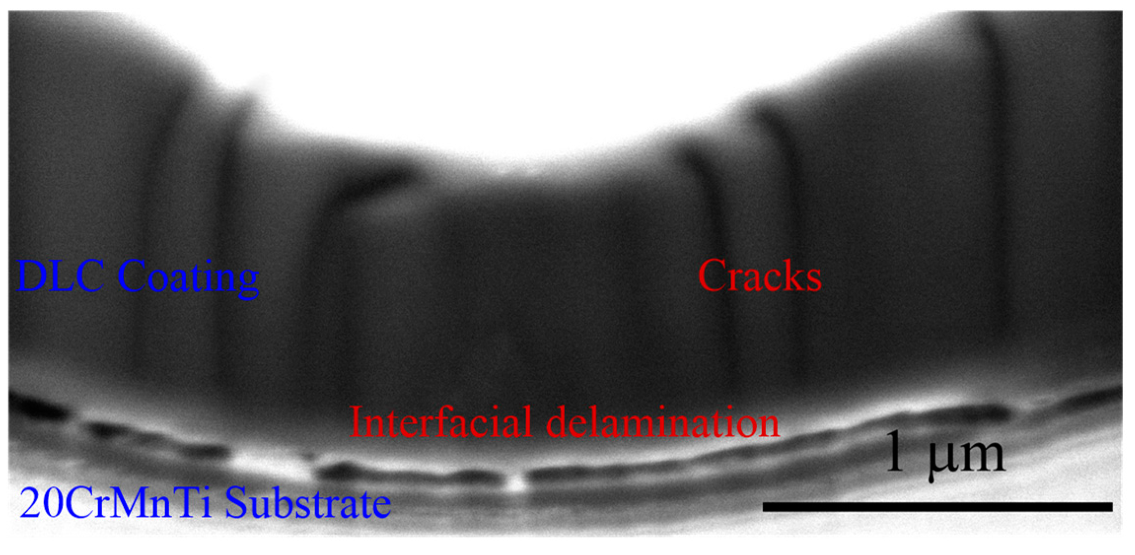
Figure 1. SEM image of a cross-section of a tested gear surface by (focused ion beam) FIB.
Coatings 09 00642 g001
Figure 2. Schematic diagram of the elastohydrodynamic lubrication (EHL) model for coated surfaces in a line contact.
Coatings 09 00642 g002
Figure 3. Computational domain of the EHL model for coated surfaces in a line contact.
Coatings 09 00642 g003
Figure 4. Bilinear constitutive model in the mixed mode.
Coatings 09 00642 g004
Figure 5. Global numerical solution scheme.
Coatings 09 00642 g005
Figure 6. Oil film pressure distribution under different coating elastic moduli: (a) overall pressure curves, (b) magnification of center pressure, and (c) secondary pressure peak.
Coatings 09 00642 g006
Figure 7. Contour of equivalent stress in the coating–substrate system for (a) a soft coating and hard substrate and (b) a hard coating and soft substrate.
Coatings 09 00642 g007
Figure 8. Distribution of σ x along the coating surface and along the interface on the coating side.
Coatings 09 00642 g008
Figure 9. Distribution of shear stress along the coating thickness direction at x = 0.153 mm.
Coatings 09 00642 g009
Figure 10. Distribution of normal and shear stresses on the interface.
Coatings 09 00642 g010
Figure 11. Evolution of coating crack and interfacial delamination in the coating–substrate system for (a) damaged coating and perfect interface, (b) perfect coating and damaged interface, and (c) damaged coating and interface.
Coatings 09 00642 g011aCoatings 09 00642 g011b
Table 1. The main parameters used for the coated EHL model.
Geometric Parameters
Radius R (m)5 × 10⁻³
Coating thickness hc (μm)2
Material properties
Elastic modulusSubstrate E s (GPa)200
Coating E c (GPa)50, 100, 400, 500
Poisson’s ratioSubstrate ν s 0.3
Coating ν c 0.3
Operating conditions
Maximum Hertzian pressure (uncoated) p h (MPa)1841
Hertzian half-width (uncoated) a (m)1.675 × 10⁻⁴
Surface velocity of body 1 u1 (m/s)5
Surface velocity of body 2 u2 (m/s)3
Lubricant properties
Ambient density of lubricant ρ 0 (kg/m3)870
Ambient viscosity of lubricant η 0 (Pa·s)0.04
Viscosity–pressure coefficient α (Pa-1)2.2 × 10⁻⁸
Eyring stress τ 0 (MPa)10
Table 2. Main parameters of cohesive zone model.
Coating [29,30]Fracture energy (J/m2) 30
Fracture strength (MPa)1440~1920
Interface [29,31]Adhesion energy (J/m2)150
Bonding strength (MPa)285~1940