Article

Single Particle Erosion Behavior of NiTi-Based Nanolaminates and Superelastic NiTi Monolayer Coatings

Mechanical Engineering Department, Dalhousie University, Halifax, NS B3H 4R2, Canada
*
Author to whom correspondence should be addressed.
Coatings 2019, 9(10), 617; https://doi.org/10.3390/coatings9100617
Submission received: 6 September 2019 / Revised: 23 September 2019 / Accepted: 25 September 2019 / Published: 27 September 2019

Abstract

:
Bulk NiTi is used to make parts, such as couplings and bearings, that can be found in many industries such as the automotive, aerospace and medical sectors. Forming and machining bulk superelastic NiTi is a very difficult and costly process; however, applying NiTi as a surface coating will provide an alternate manufacturing method that will minimize machining processes. The objective of this study is to produce a superelastic NiTi-based surface coating that exhibits denting, impact and wear resistance. Superelastic NiTi has been successfully produced through vacuum deposition processes, despite this, there is a lack of a full and comprehensive study on the formation of the NiTi phase during coating development. In this study, the NiTi phase is fabricated through the annealing of sputtered deposited Ti and Ni layers in a coating. To confirm the presence of the intermetallic phases, X-ray diffraction (XRD) and energy dispersive spectrometry (EDS) analysis were performed. The erosion behavior of the coating is evaluated through single particle erosion testing, which resulted in the coatings that contained the NiTi precipitates to exhibit the best damage resistance compared to the other nanolaminates. This indicates that the superelastic NiTi phase increases the resistance to impacting particles. Microstructural evolution and NiTi formation during annealing is discussed and related to the observed damage resistance of the coatings.

1. Introduction

The erosion of working parts cost industries millions of dollars each year. The effects of erosion can lead to a loss of process efficiency, plant shutdowns and safety risks [1]; ultimately causing production delays which result in a significant increase in costs. A common method to prevent erosion is to protect the material by applying a surface coating that can withstand erosion.
Erosion occurs when particles impact a solid surface and the kinetic energy is transferred to the material [2,3]. Erosion is influenced by operational properties, such as particle velocity, impact angle and the impacting particle, such as hardness, size and shape [4]. The kinetic energy can also be totally or partially dissipated in the material through ductility, phase transformations and heat [2]. Erosion-resistant coatings can be found in many industries, including aerospace, oil and gas and automotive. However, a material that has not been fully exploited for erosion-resistant purposes in commercial applications is bulk NiTi.
Bulk NiTi is ideal for erosion applications because it exhibits a stress-induced reversible martensitic phase transformation, which leads to a unique superelasticity effect. When an external stress is applied to austenitic NiTi, it prompts a phase transformation to detwinned martensite and unloading the stress results in the reverse transformation back to its parent austenitic phase. A superelastic NiTi alloy has the capability to recover large strains from 6% to 8% [5,6], which is much greater than other metallic alloys. The superelasticity effect improves the mechanical properties [7,8,9,10], such as higher strength and lower elastic modulus. Consequently, this stressed-induced phase transformation makes the material very difficult to form and machine, which restricts the commercial applicability of NiTi [11,12].
A proposed alternative NiTi fabrication method is to apply NiTi as a surface coating, as this would minimize the machining processes required. Currently, there is no commercial method to apply NiTi has a surface coating. Few studies [13,14,15,16] have used vacuum deposition processes, with varying successes, to apply NiTi as a surface coating, furthermore, the deposition of NiTi as a surface coating is a costly and complex process. Several studies [9,17,18] formed the NiTi phase by subjecting sputter deposited Ni and Ti layers to a heat treatment process. Cho et al. [18] validated that austenitic NiTi was formed at the interface after the annealing of sputter deposited Ni and Ti layers. The sequence and growth of Ni and Ti intermetallic phases in diffusion couples have been studied [19,20,21,22,23], however, a comprehensive study on the formation and growth mechanisms of NiTi is non-existent.
Annealing Ni and Ti in a nanolaminate could be a viable option for components that experience a high rate of damage in any industry such as pipe bends, bearings and hydraulic components. In this study, the formation of superelastic NiTi is attempted through the annealing of sputtered deposited layers of Ni and Ti. Furthermore, a sputter deposited 50 μm monolayer of superelastic NiTi was fabricated for comparison. The damage behavior of both coatings was assessed using single particle impact testing, as it allows for the damage mechanisms of the coating, such as deformation and fracture, to be closely examined [24], compared to “multi-particle” dry or slurry erosion testing. The single particle erosion test in this study evaluates the coatings’ response to denting by high velocity particle at different impact angles. This test simulates a single impact event in an erosive environment or an incidental particle impact during operation.

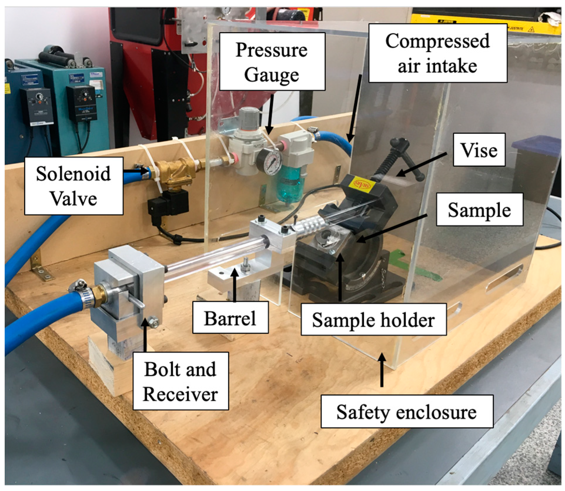
2. Experimental Procedure

Plain carbon steel substrates were ground with SiC 240, 320, 420 and 600 grit paper and were polished with 9, 3 and 1 μm diamond paste. A DC magnetron sputtering system was employed to deposit a 50 μm monolayer of superelastic NiTi, with a transformation temperature of approximately 0 °C onto plain carbon steel substrates. Initially, the air within the chamber was completely removed to allow a pure inert gas to be passed through. During sputtering the system was kept at a pressure of 1 × 10⁻⁷ mbar and argon gas was pumped through the system at a rate of 20 cm3 per minute [6].
The nanolaminate coatings were fabricated through a direct current (DC) magnetron sputtering process. The steel substrates are secured onto a 100 mm silicon wafer, the wafer is then placed on a sample holder. The air was removed from the chamber and argon gas was passed through at a base pressure of 1.33 × 10⁻⁷ mbar by a cryopump. Ni and Ti were deposited in alternating 100 nm thick layers, for a total coating thickness of 1 μm. To form the NiTi phase in the nanolaminates, the coatings were subjected to an annealing process. The coatings were placed in a vacuum furnace and heated at a rate of 20 °C per minute to 650 and 800 °C where they were held for one hour under a vacuum of 3 × 10⁻⁵ mbar. The nanolaminates were then moderately cooled at an approximate rate of 10 °C per minute to room temperature.
Each coating was sectioned and was examined under both a Hitachi S-4700 scanning electron microscope (Hitachi, Tokyo, Japan) and energy dispersive spectrometry (Hitachi, Tokyo, Japan) to assess coating quality and to determine elemental composition. Additionally, the crystalline phases in the nanolaminates were determined using a Bruker D8 advanced X-ray diffraction (BRUKER, Billerica, MA, USA) system. Each coating was analyzed using Cu-Kα radiation with a wavelength of 1.54 Å, from 20° to 120° (2θ) and the generated peaks were identified using Powder Diffraction Files (PDF). The XRD tests were done using fast (5°/min) and slow (0.5°/min) scans.
Hardness and elastic modulus values were determined through load-controlled Micro Material Nano Test Platform 3 (Mirco Materials, Wrexham, UK) nanoindentation system. Here, loads ranging from 5 to 25 mN were applied with a Berkovich diamond indenter to the coating in the same location. Initially, a load of 5 mN was applied and unloaded to 3 mN, this cycle was repeated with the load increasing by 5 mN each time up to a 25 mN load. These cycles were repeated 10 to 15 times in different locations on the coating and both the elastic modulus and hardness values were calculated after each unloading cycle. From this data, the hardness and elastic modulus values were determined from the best-fit equations, of H and E versus depth curves, for each coating at a depth of 200 nm to minimize substrate effects.
Single particle erosion test was performed at room temperature using an in-house built apparatus, seen in Figure 1. A hard tungsten carbide (WC–6 wt.% Co) spherical ball with a diameter of 1 mm was placed into the receiver, then the bolt was connected to allow compressed air to fire it at the sample. The sample was loaded into the holder, placed in the vise and the impact angle of 90°, 60°, 45° or 30° was selected. The vise was then placed approximately 1 cm away from the end of the barrel. After the safety enclosure was placed over the end of the barrel and vise, the pressure gage was set to a specific pressure and the solenoid valve was opened; allowing the compressed air to push the particle towards the target.
The gas pressure gauge was adjusted to the desired velocity of the impacting particle. The velocity was measured by an Arduino (Somerville, MA, USA) that calculated the time needed for the particle to pass through two photo-interrupters that were placed 0.003 m apart, the time was then inputted into Equation (1) to determine the velocity (up).
u p ( m s ) = Distance   between   the   photo   interruptors   ( m ) Time   for   particle   to   pass   both   the   photo   interruptors ( s )
In this study, a pressure of 60 psi was selected, to ensure that the mean contact force is above that needed to initiate the NiTi transformation; which was determined to be 0.410 GPa [25]. A pressure of 60 psi results in a velocity of approximately 53 m·s−1. The impact sites were analyzed using SEM, EDS, laser confocal microscope (Keyence, Osaka, Japan) and an optical microscope (Olympus, Tokyo, Japan).

3. Results and Discussion

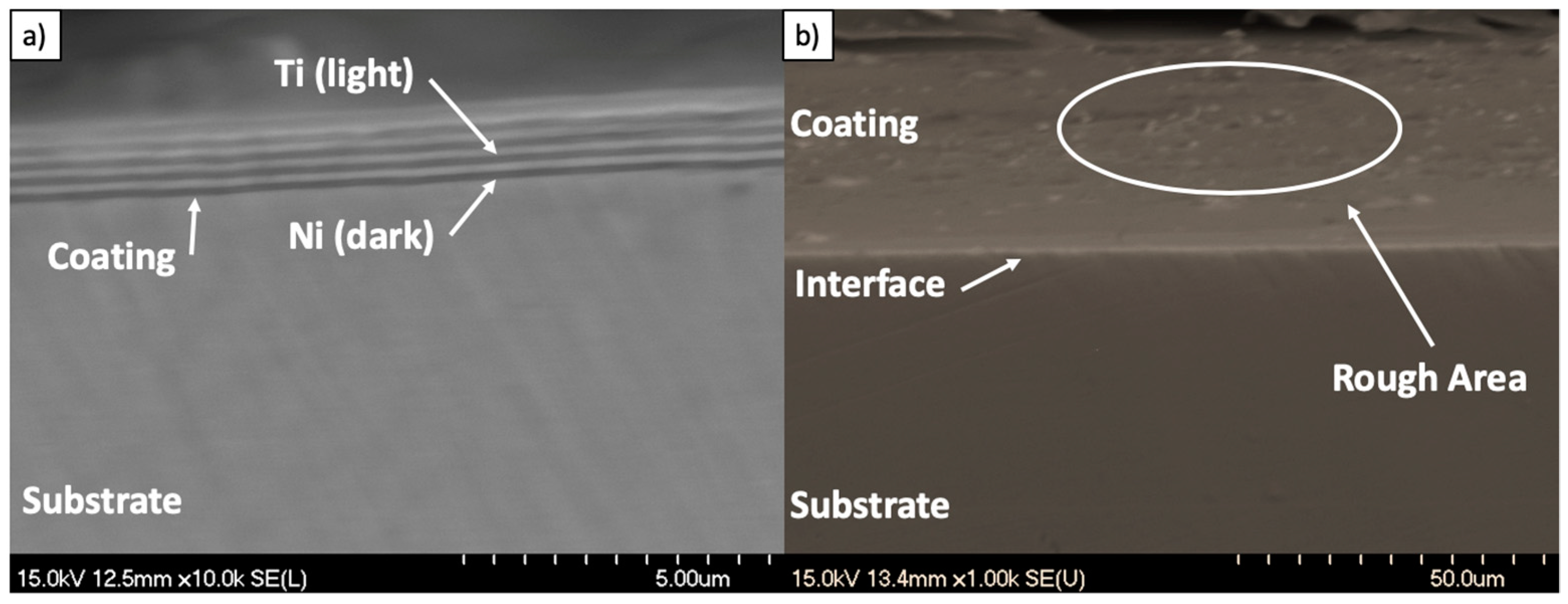
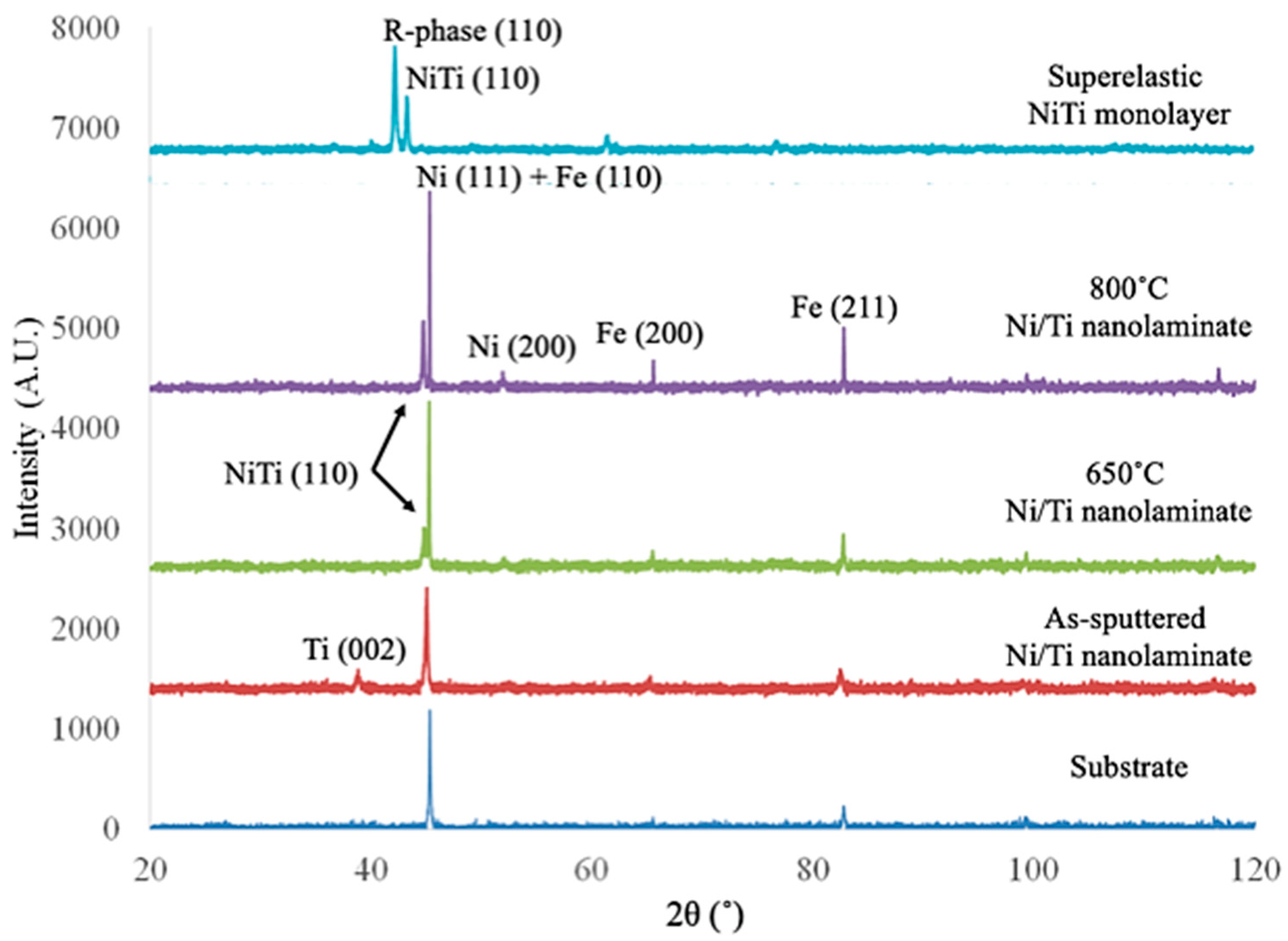
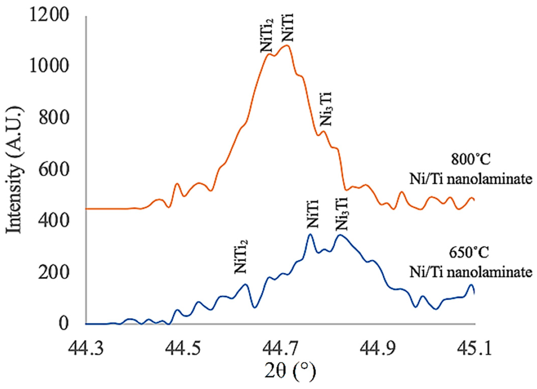
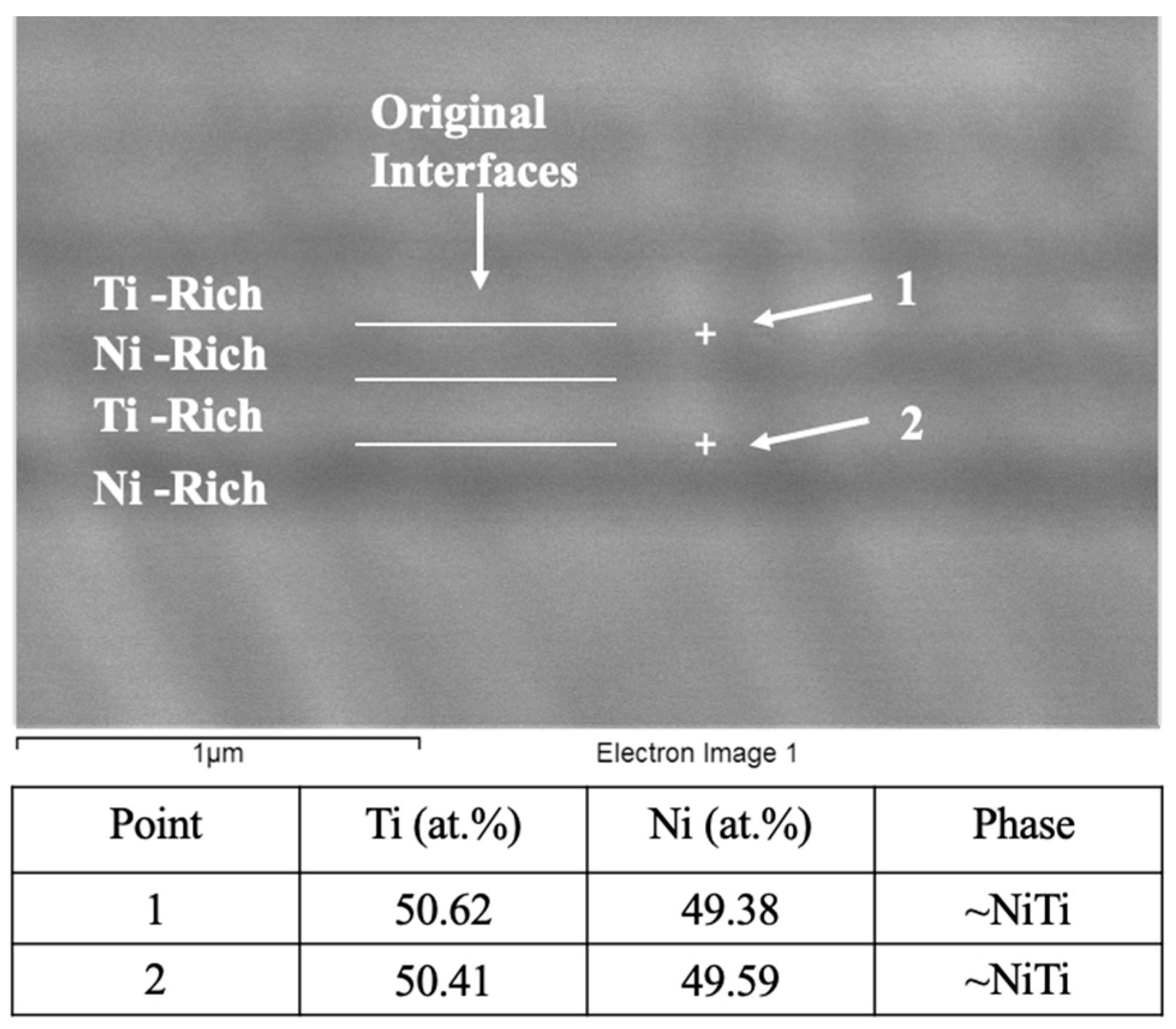
3.1. Characterization of the Coatings

The superelastic NiTi monolayer and the 650 °C nanolaminate coating have excellent adhesion with the substrate, as seen in Figure 2a,b, respectively. The 650 °C nanolaminate shows dark Ni-rich areas and light Ti-rich areas, as identified by EDS, furthermore, the diffusion layer was not clearly identified under SEM. The cross-section of the superelastic NiTi monolayer was sputtered uniformly and through EDS analysis had a composition of 50.58 at.% Ni and 47.23 at.% Ti. The NiTi monolayer coating shows rough areas after sectioning, which are caused by the stress of the saw blade initiating the NiTi phase transformation, thus, resulting in a rough surface finish. This further highlights the main challenge associated with machining and forming superelastic NiTi.
XRD patterns, seen in Figure 3, were gathered from each coating to determine if any intermetallic phases were formed during annealing, specifically austenitic NiTi. The as-sputtered pattern shows a peak at 38° (2θ) which was identified as the Ti (002) peak. This peak does not appear in the coatings that were annealed, indicating a reaction between Ti and Ni had taken place to create intermetallic phases. That is, the amount of Ti is reduced to a level where it is difficult to observe its corresponding peaks. The coatings annealed at 650 and 800 °C and the superelastic NiTi monolayer, show the NiTi (110) intermetallic peak at 44° (2θ), demonstrating that superelastic austenitic NiTi is formed at these temperatures. The Fe (110), (200) and (211) peaks from the substrate are clearly seen in all nanolaminate coatings. It is difficult to see the Ni (111) peak as it overlaps with the strong Fe (110) peak, however, the Ni (200) is slightly visible.
The NiTi-based nanolaminates were designed to obtain the equiatomic NiTi phase, at each Ni and Ti interface, through the annealing of Ni and Ti sputtered deposited layers. According to research performed by Hu [19] and Garay [26], when annealing elemental Ni and Ti, the intermetallic phases form and grow in a specific sequence, starting with Ni3Ti, followed by NiTi2 and finally NiTi. The XRD patterns show only the NiTi intermetallic peak formed after annealing, however, there are three intermetallic phases that Ni and Ti can form; NiTi2, NiTi and Ni3Ti.
Therefore, slow-scan XRD diffraction patterns for the 650 and 800 °C nanolaminates (Figure 4) were performed and closely examined in the 2θ range of 44° to 45° for the 650 and 800 °C coatings. The slow-scan patterns show a combination of the three intermetallic phases. This is consistent with the intermetallic phase that was present in diffusion couple literature theories [19,26].
To further confirm that the NiTi intermetallic phase is present in the annealed 650 °C nanolaminate coating, EDS was used to examine the regions around the Ni/Ti interfaces, seen in Figure 5. The results show that approximately equiatomic NiTi precipitates have formed within the reaction zones, which is in agreement with XRD data (Figure 3).
Nanoindentation testing was performed on the coatings to determine elastic modulus and hardness values. The data, seen in Table 1, shows that the nanolaminate coatings have higher hardness (H) and elastic modulus (E) values compared to the superelastic NiTi monolayer. The 650 °C nanolaminate has the highest hardness of all coatings, which is advantageous for erosion resistance. Nanocomposites with high hardness and toughness can prevent (or slow down) crack growth and inhibit crack initiation [27].
The annealed Ni/Ti nanolaminates exhibit higher hardness values compared to the superelastic monolayer due to the property gradient between the Ni, Ti and NiTi phases. The Koehler effect [28] states that as dislocations in a low elastic modulus material move towards the interface of a material with a higher elastic modulus, it will cause dislocation pile-up. Thus, dislocation pile-up will occur in at the interfaces between NiTi and the adjacent Ni and Ti layers in the 650 and 800 °C nanolaminate coatings.
The nanoindentation data was also used to determine the E/H ratio and the elastic recovery ratio for each coating. The elastic recovery ratio is the ratio of the area under the unloading curve to the area under the loading curve. The NiTi monolayer and 650 °C nanolaminates exhibit comparable E/H and elastic recovery ratios, which highlight the presence of superelastic NiTi in the 650 °C coating. Low E/H and high elastic recovery ratios indicate a more resilient and wear resistant behavior. It is clear from Table 1 that the 650 °C and the NiTi monolayer coatings exhibit enhance properties over the as-sputtered coating.

3.2. Erosion Behavior of the Coatings

The mean contact pressure exerted by the impacting particles was calculated to ensure that the force was large enough to initiate the NiTi phase transformation. The mean contact pressure (pm) is the pressure induced by the indenter over the contact area, described in Equation (2).
p m = P π a 2
where P is the applied load. The contact radius, a, can be calculated using Equation (3) where R is indenter radius and E* is the reduced modulus.
a 3 =   3 P R 4 E *
To calculate the applied force of the impacting particle, the kinetic energy is equated to the work done by the particle, as seen in Equation (4) [29]. This equation works under the assumption that the friction and drag effects of the impacting particle are negligible.
P d = 1 2 m p v p 2 sin ϕ
where d is the distance the particle travels, mp is the mass of the particle, vp is the velocity of the impacting particle and ϕ is the impact angle. From this, the mean contact pressure can be calculated to determine the mean contact pressure exerted at each angle, as seen in Table 2. At a 30° angle, the mean contact pressure is below that of the NiTi initiation stress of 0.410 GPa [25]; However, given the uncertainty in the exact composition of the NiTi precipitates, hence, uncertainty in the exact transition stress, as well as, uncertainty in the exact incident angle, it is reasonable to assume that even at low impact angle some martensitic transformation can take place, given the small difference between the contact pressure and the reported transformation stress.

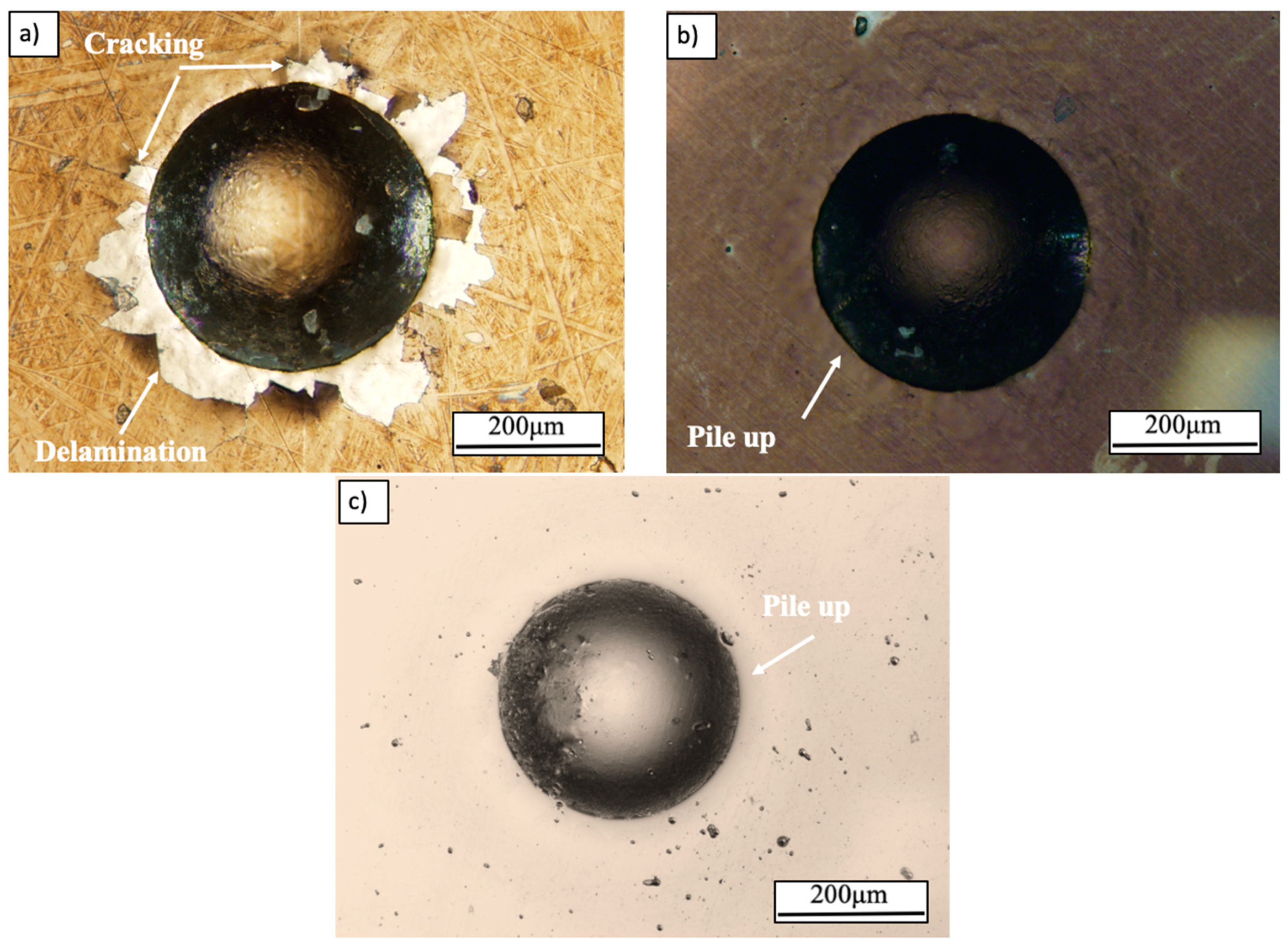
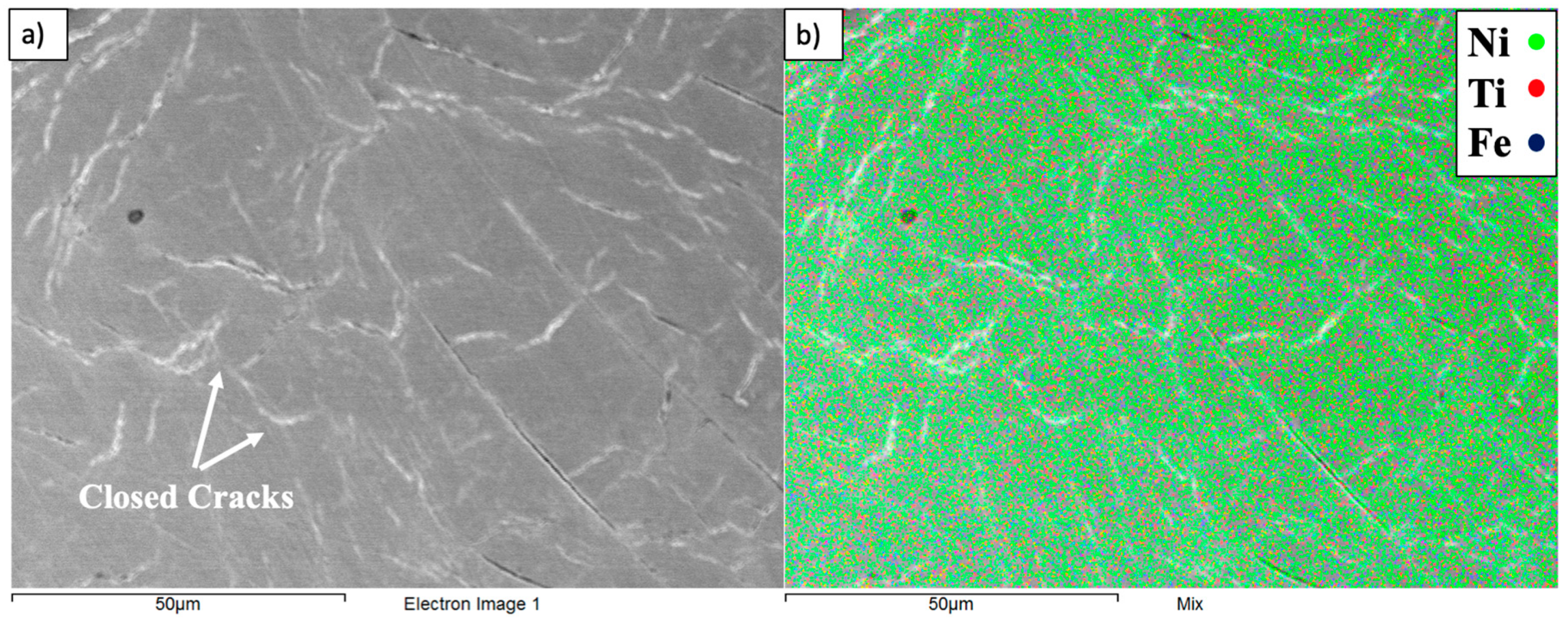
3.2.1. High-Angle Fracture Mechanisms

The high-angle impacts of the as-sputtered and 650 °C nanolaminates and monolayer of NiTi coatings can be seen in Figure 6. The as-sputtered coating, Figure 6a, shows severe delamination and coating removal from around and within the impact site. Upon impact, the high Hertzian-type surface tensile stresses result in the initiation and propagation of cracks, which then propagated and resulted in the spalling of the coating. Conversely, the 650 °C nanolaminate, Figure 6b and the monolayer of superelastic NiTi, Figure 6c, result in no delamination. The 650 °C nanolaminate shows only few fine micro-cracks, due to the superelasticity effect of NiTi precipitates. Upon impact of both 650 °C nanolaminate and superelastic NiTi, some of the energy is absorbed by the NiTi phase during its transformation from austenite to martensite. Once the applied load of the impacting particle is removed, the reverse phase transformation occurs and some of the elastic strains are recovered. As a result of the superelastic effect only limited energy is available to initiate and propagate cracks, hence, only few micro-cracks were observed in the 650 °C coating post impact.
A close inspection of the 90° impact site on the 650 °C nanolaminate showed some cracking within the impact site, as seen in Figure 7a. Here, cracks appear to be close, which is believed to be a result of the NiTi superelastic effect. As NiTi undergoes a transformation from austenite to detwinned martensite it expands and generates a compressive stress field in its vicinity. Hence, causes cracks to close and prevents them from propagating. This minimizes the extent of surface damage done to the coating. This is evidence that the phase transformation occurred in the coating upon impact. Figure 7b is an EDS map that shows that the closed cracks do not expose the substrate.

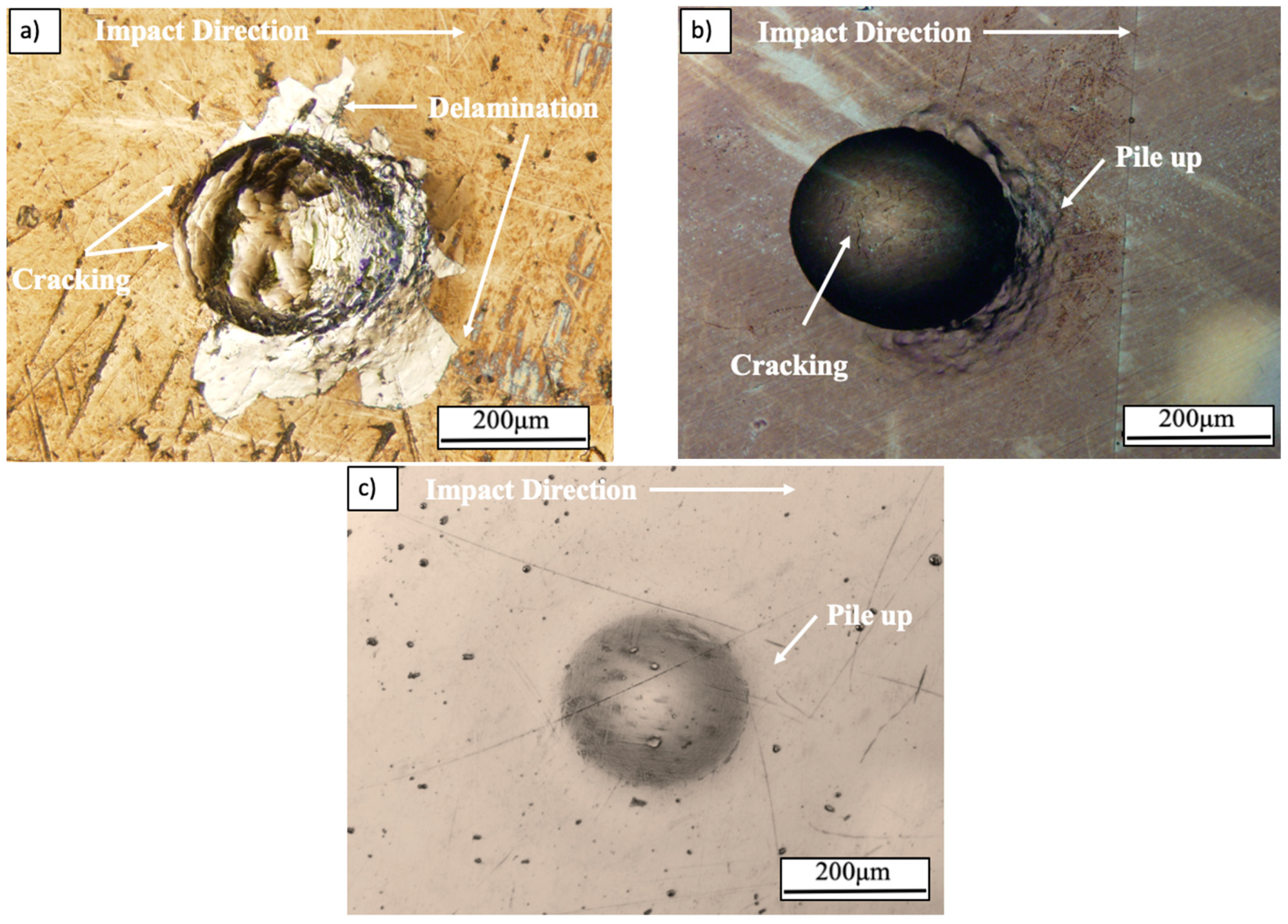
3.2.2. Low-Angle Fracture Mechanisms

The low-angle particle impact resulted in elliptical craters, as seen in Figure 8. Upon impact, of the as-sputtered nanolaminate the coating and substrate were displaced in the direction of impact resulting in the lifting and delamination of the coating around and within the impact crater, as seen in Figure 8a. On the other hand, the 650 °C nanolaminate shows few cracks within the indent and no delamination. As the impact occurs, the kinetic energy is transferred to the coating and dissipated through both the initiation and propagation of fine cracks (micro-cracks). When the cracks encounter the NiTi phase, the cracking energy is consumed by the phase transformation and further cracking is prohibited due to the compressive strain fields caused by the formation of the martensitic NiTi phase. The fracture resistance of the superelastic monolayer and 650 °C nanolaminate coatings is enhanced due to the NiTi precipitates ability to dissipate cracking energy through the phase transformation effect, seen in Figure 8b,c, respectively.
The impacting particle was examined for evidence of adhesive wear after testing of the as-sputtered nanolaminate. The WC ball used for impacting, Figure 9, shows evidence of adhesive wear. As the hardness of the WC ball is much larger than that of the as-sputtered coating, is believed that upon impact of the particles, the as-sputtered nanolaminate coating fractured and adhered to the surface of the particle.

3.2.3. Erosion Mechanisms of the Coatings

The transformation toughening ability of the monolayer of superelastic NiTi resulted in no measurable material removal, at both high and low impact angles, as seen in Figure 10. Superelastic NiTi has the ability to resist erosive wear due to its superelastic effect [30]; resulting in the kinetic energy being dissipated through the reversible phase transformation. The low-angle impact sites show that the material was displaced in the direction of impact, whereas the 90° evenly displaces the material around the indent. Material pile-up is clearly seen in the depth profiles in Figure 10.
The confocal images and depth profiles for the 650 °C nanolaminate are shown in Figure 11. Similar to the monolayer NiTi, the 650 °C nanolaminate undergoes material displacement and pile-up formation in the direction of particle impact. Although the crater sizes in the 650 °C nanolaminate seem to be larger than those for the monolayer NiTi coating, the material removal is minimal.
Furthermore, the 650 °C nanolaminate experienced transformation toughening at high and low impact angles. No visible cracks were detected in the confocal image. The transfer of kinetic energy of the particle is dissipated mainly through the martensitic transformation. Any fine cracks that may form are prevented from any significant propagation by the NiTi precipitate. Here, the crack energy is absorbed by the NiTi precipitates as they transform from austenite to martensite, during transformation, the NiTi precipitates expand and create a compressive stress field in their vicinity which assists in closing cracks. The material pile-up is comparable to the superelastic NiTi coating.
It is understood that the depths of deformation during the single particle impacts are larger than the 1 μm thickness of the nanolaminate coatings. It should be emphasized here that the failure criteria used in these coatings is their ability to resist fracture and delamination. Although the crater depths include the contribution from the steel substrate, it gives an understanding of the coating and substrate system behavior. Furthermore, cracking of the coatings although is considered failure, if it occurs, it may not contribute to material removal during erosion; therefore, the erosion data in this study should be used with this understanding. The purpose here is to simulate a real single impact event due to erosion or incidental impact by a particle in service of a substrate/coating system.

4. Conclusions

In conclusion, the annealing of sputter deposited Ni and Ti layers successfully resulted in the formation of the austenitic NiTi phase. After annealing at 650 °C, the nanolaminate coating exhibit comparable E/H and elastic recovery ratios to that of a monolayer of superelastic NiTi, yet, it has higher hardness. Upon impact of the as-sputtered nanolaminate, cracks were initiated and propagated, which lead to the spalling of the coating. When impacting the nanolaminates annealed at 650 and 800 °C, results in few fine cracks and no spalling. This increase in erosion resistance is likely due to the presence of NiTi precipitates. The martensitic reversible transformation associated with superelastic NiTi gives rise to substantial toughening of the coatings. Fabricating NiTi coating through annealing of Ni and Ti layers may provide a feasible path to applying superelastic NiTi-based coatings in an attempt to minimize machining and forming costs associated with using bulk NiTi.

Author Contributions

N.C. and Z.F. conceived and designed the experiments; N.C. performed the experiments; N.C. analyzed the data; N.C. writing—original draft preparation; Z.F. contributed materials and revised the paper; Z.F. funding acquisition; and N.C. and Z.F. writing—review and edited the paper.

Funding

We would like to express our thanks to NSERC (National Scientific and Engineering Research Council of Canada) for their financial assistance (through grant number RGPIN 327449) that made this research study viable.

Conflicts of Interest

The authors declare no conflict of interest.

References

  1. Davis, J.R. Introduction to Surface Engineering for Corrosion and Wear Resistance in Surface Engineering for Corrosion and Wear Resistance; ASM International: Materials Park, OH, USA, 2001; pp. 1–10. [Google Scholar]
  2. Bousser, E.; Martinu, L.; Klemberg-Sapieha, J.E. Solid particle erosion mechanisms of protective coatings for aerospace applications. Surf. Coat. Technol. 2014, 257, 165–181. [Google Scholar] [CrossRef] [Green Version]
  3. Bhushan, B. Wear, in Introduction to Tribology; Wiley: New York, NY, USA, 2002; pp. 331–410. [Google Scholar]
  4. Stachowiak, G.W.; Batchelor, A.W. Engineering Tribology, 4th ed.; Butterworth-Heinemann: Oxford, UK, 2013. [Google Scholar]
  5. Morgan, N.B.; Friend, C.M. Shape Memory Alloys. In Smart Technologies; World Scientific: River Edge, NJ, USA, 2003; pp. 109–139. [Google Scholar]
  6. De Miranda, R.L.; Zamponi, C.; Quandt, E. Micropatterned freestanding superelastic TiNi films. Adv. Eng. Mater. 2013, 15, 66–69. [Google Scholar] [CrossRef]
  7. Mehrabi, K.; Bahmanpour, H.; Shokuhfar, A.; Kneissl, A. Influence of chemical composition and manufacturing conditions on properties of NiTi shape memory alloys. Mater. Sci. Eng. A 2008, 481–482, 693–696. [Google Scholar] [CrossRef]
  8. Yuan, X.-B.; Chen, B.; Liu, F.-S.; Xu, Q.; Ma, W. Transformation behaviors and superelasticity of Ti50Ni48Fe2 shape memory alloy subjected to cold-rolling and subsequent annealing. Rare Met. 2014, 33, 652–656. [Google Scholar] [CrossRef]
  9. Lehnert, T.; Tixier, S.; Böni, P.; Gotthardt, R. A new fabrication process for Ni–Ti shape memory thin films. Mater. Sci. Eng. A 1999, 273–275, 713–716. [Google Scholar] [CrossRef]
  10. Matsunaga, T.; Kajiwara, S.; Ogawa, K.; Kikuchi, T.; Miyazaki, S. High strength Ti–Ni-based shape memory thin films. Mater. Sci. Eng. A 1999, 273–275, 745–748. [Google Scholar] [CrossRef]
  11. Kulkarni, V.N.; Gaitonde, V.N.; Hadimani, V.; Aiholi, V. Analysis of wire EDM process parameters in machining of NiTi superelastic alloy. Mater. Today Proc. 2018, 5, 19303–19312. [Google Scholar] [CrossRef]
  12. Kaynak, Y.; Robertson, S.W.; Karaca, H.E.; Jawahir, I.S. Progressive tool-wear in machining of room-temperature austenitic NiTi alloys: The influence of cooling/lubricating, melting, and heat treatment conditions. J. Mater. Process. Technol. 2015, 215, 95–104. [Google Scholar] [CrossRef]
  13. Ni, W.; Cheng, Y.-T.; Lukitsch, M.; Weiner, A.M.; Lev, L.C.; Grummon, D.S. Novel layered tribological coatings using a superelastic NiTi interlayer. Wear 2005, 259, 842–848. [Google Scholar] [CrossRef]
  14. Tillmann, W.; Momeni, S. Deposition of superelastic composite NiTi based films. Vacuum 2014, 104, 41–46. [Google Scholar] [CrossRef]
  15. Zhang, Y.; Cheng, Y.-T.; Grummon, D.S. The influence of superelastic NiTi interlayers on tribological properties of CrN hard coatings. Mater. Sci. Eng. A 2006, 438–440, 710–713. [Google Scholar] [CrossRef]
  16. Zhang, Y.; Cheng, Y.-T.; Grummom, D.S. Novel tribological systems using shape memory alloys and thin films. Surf. Coat. Technol. 2007, 202, 998–1002. [Google Scholar] [CrossRef]
  17. Behera, A.; Aich, S. Characterisation and properties of magnetron sputtered nanoscale bi-layered Ni/Ti thin films and effect of annealing. Surf. Interface Anal. 2015, 47, 805–814. [Google Scholar] [CrossRef]
  18. Cho, H.; Miyazaki, S. TiNi multilayer thin films. In Thin Film Shape Memory Alloys: Fundamentals and Device Applications; Miyazaki, S., Fu, Y.Q., Huang, W.M., Eds.; Cambridge University Press: New York, NY, USA, 2009; pp. 110–123. [Google Scholar]
  19. Hu, L.; Xue, Y.; Shi, F. Intermetallic formation and mechanical properties of Ni–Ti diffusion couples. Mater. Des. 2017, 130, 175–182. [Google Scholar] [CrossRef]
  20. Zhou, Y.; Wang, Q.; Sun, D.L.; Han, X.L. Co-effect of heat and direct current on growth of intermetallic layers at the interface of Ti–Ni diffusion couples. J. Alloys Compd. 2011, 509, 1201–1205. [Google Scholar] [CrossRef]
  21. Meng, Q.; Yang, H.; Liu, Y.; Nam, T. Compositionally graded NiTi plate prepared by diffusion annealing. Scr. Mater. 2012, 67, 305–308. [Google Scholar] [CrossRef]
  22. Li, B.-Y.; Rong, L.-J.; Li, Y.-Y. Anisotropy of dimensional change and its corresponding improvement by addition of TiH2 during elemental powder sintering of porous NiTi alloy. Mater. Sci. Eng. A 1998, 255, 70–74. [Google Scholar] [CrossRef]
  23. Green, S.M.; Grant, D.M.; Kelly, N.R. Powder metallurgical processing of Ni–Ti shape memory alloy. Powder Metall. 1997, 40, 43–47. [Google Scholar] [CrossRef]
  24. Takaffoli, M.; Papini, M. Material deformation and removal due to single particle impacts on ductile materials using smoothed particle hydrodynamics. Wear 2012, 274–275, 50–59. [Google Scholar] [CrossRef]
  25. Zhang, C.; Farhat, Z.N. Sliding wear of superelastic TiNi alloy. Wear 2009, 267, 394–400. [Google Scholar] [CrossRef]
  26. Garay, J.E.; Anselmi-Tamburini, U.; Munir, Z.A. Enhanced growth of intermetallic phases in the Ni–Ti system by current effects. Acta Mater. 2003, 51, 4487–4495. [Google Scholar] [CrossRef]
  27. Bousser, E.; Martinu, L.; Klemberg-Sapieha, J.E. Solid particle erosion mechanisms of hard protective coatings. Surf. Coat. Technol. 2013, 235, 383–393. [Google Scholar] [CrossRef]
  28. Koehler, J.S. Attempt to design a strong solid. Phys. Rev. B 1970, 2, 547–551. [Google Scholar] [CrossRef]
  29. ASM International Handbook Committee. Friction, Lubrication, and Wear Technology; ASM International Handbook Committee: Materials Park, OH, USA, 1992; Volume 18. [Google Scholar]
  30. Yang, L.M.; Tieu, A.K.; Dunne, D.P.; Huang, S.W.; Li, H.J.; Wexler, D.; Jiang, Z.Y. Cavitation erosion resistance of NiTi thin films produced by Filtered Arc Deposition. Wear 2009, 267, 233–243. [Google Scholar] [CrossRef] [Green Version]
Figure 1. Single particle erosion apparatus.
Coatings 09 00617 g001
Figure 2. Cross-sections of (a) 650 °C nanolaminate and (b) superelastic NiTi monolayer coatings.
Coatings 09 00617 g002
Figure 3. X-ray diffraction (XRD) patterns of nanolaminate coatings.
Coatings 09 00617 g003
Figure 4. XRD slow-scan of 650 and 800 °C nanolaminate coating around the NiTi (110) peak.
Coatings 09 00617 g004
Figure 5. Energy dispersive spectrometry (EDS) of 650 °C nanolaminate cross-section.
Coatings 09 00617 g005
Figure 6. Single particle 90-degree impact (a) as-sputtered (b) 650 °C nanolaminate (c) superelastic NiTi coatings.
Coatings 09 00617 g006
Figure 7. Impact site of 650 °C nanolaminate (a) scanning electron microscopy (SEM) and (b) EDS map of 90° impact.
Coatings 09 00617 g007
Figure 8. Single particle 30-degree impact (a) as-sputtered (b) 650 °C nanolaminate (c) superelastic NiTi coatings.
Coatings 09 00617 g008
Figure 9. WC ball used to impact as-sputtered coating.
Coatings 09 00617 g009
Figure 10. Monolayer of superelastic NiTi coating impacts profiles at a 90° (a) confocal (b) depth profile and at a 30° impacts (c) confocal and (d) depth profile.
Coatings 09 00617 g010
Figure 11. Nanolaminate annealed at 650 °C impact profiles at a 90° (a) confocal (b) depth profile and at a 30° impact (c) confocal and (d) depth profile.
Coatings 09 00617 g011
Table 1. Nanoindentation data.
CoatingH (GPa)E (GPa)E/H RatioElastic Recovery Ratio
As-Sputtered8.5390.446.20.22
650 °C9.5224.423.70.38
800 °C8.8259.629.40.30
Superelastic NiTi5.681.514.40.64
Table 2. Single particle impact mean contact pressure.
Impact Angle (°)Applied Load (N)Mean Contact Pressure (GPa)
300.0200.381
450.0290.428
600.0350.458
900.0400.480

