Plasma Electrolytic Oxidation (PEO) Layers from Silicate/Phosphate Baths on Ti-6Al-4V for Biomedical Components: Influence of Deposition Conditions and Surface Finishing on Dry Sliding Behaviour


 ,
,  and
and
Abstract
:1. Introduction
2. Materials and Methods
2.1. Materials
2.2. PEO Treatment
2.3. Microstructural and Micro-Mechanical Characterization
2.4. Dry Sliding Tests
2.5. References for the Comparison of Tribological Behaviour
3. Results and Discussion
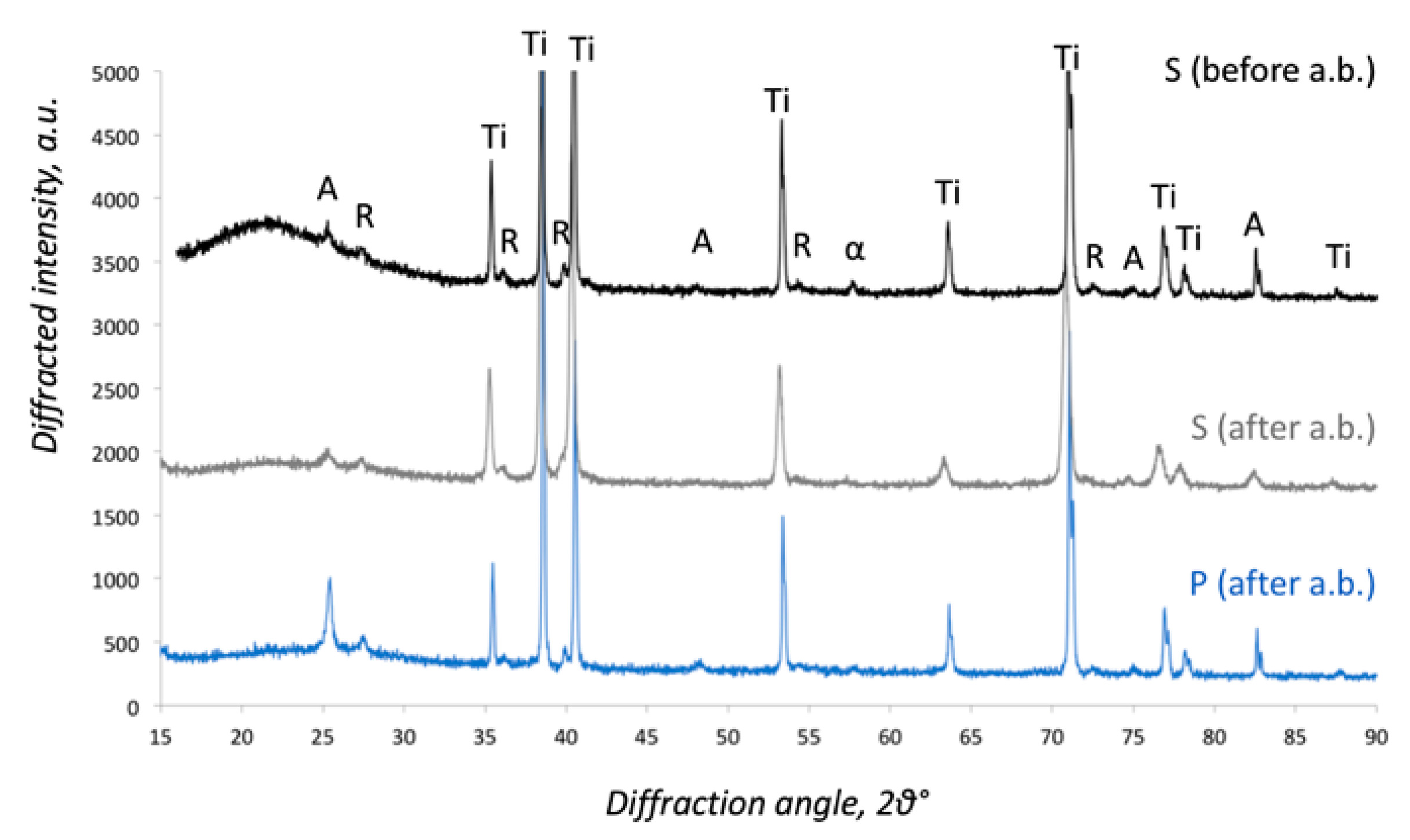
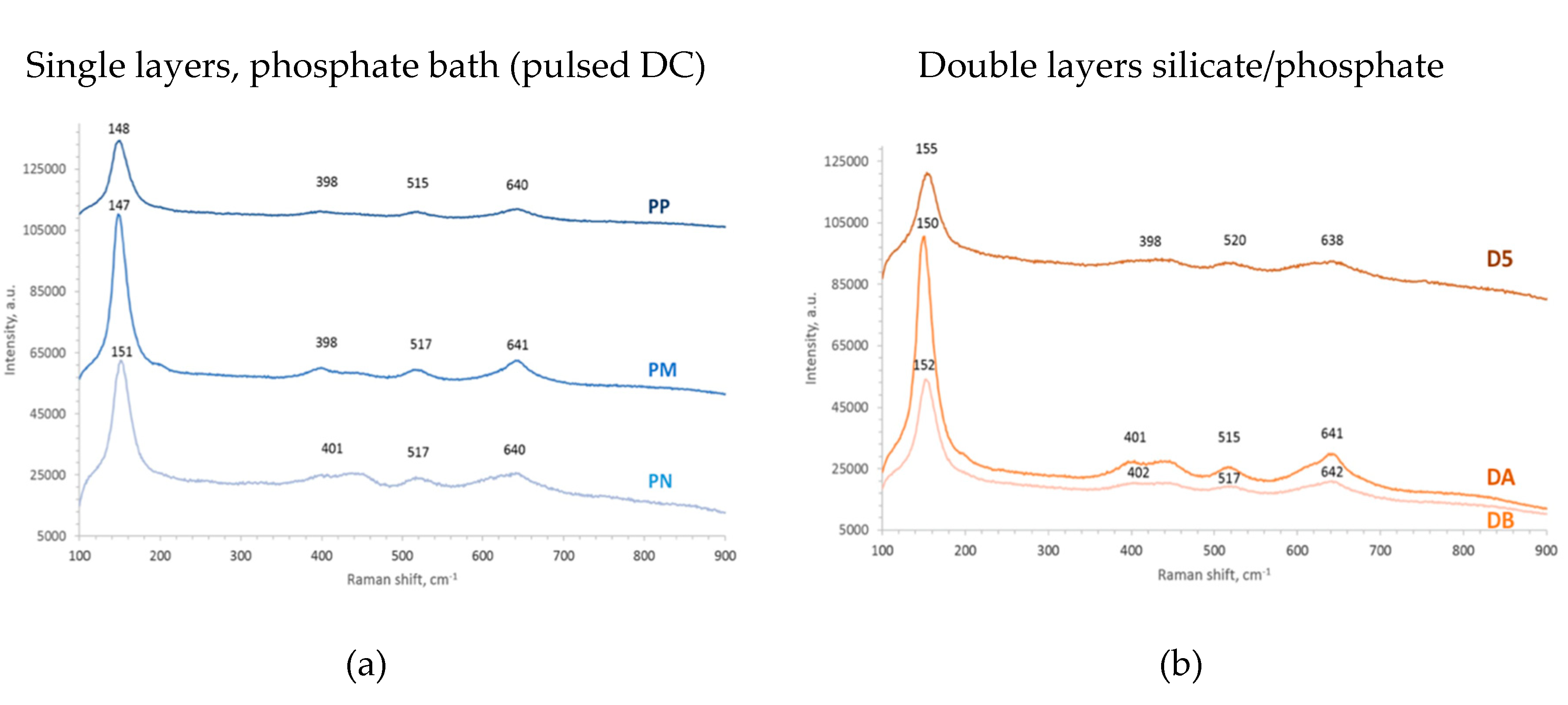
3.1. Phase Composition (General Remarks)
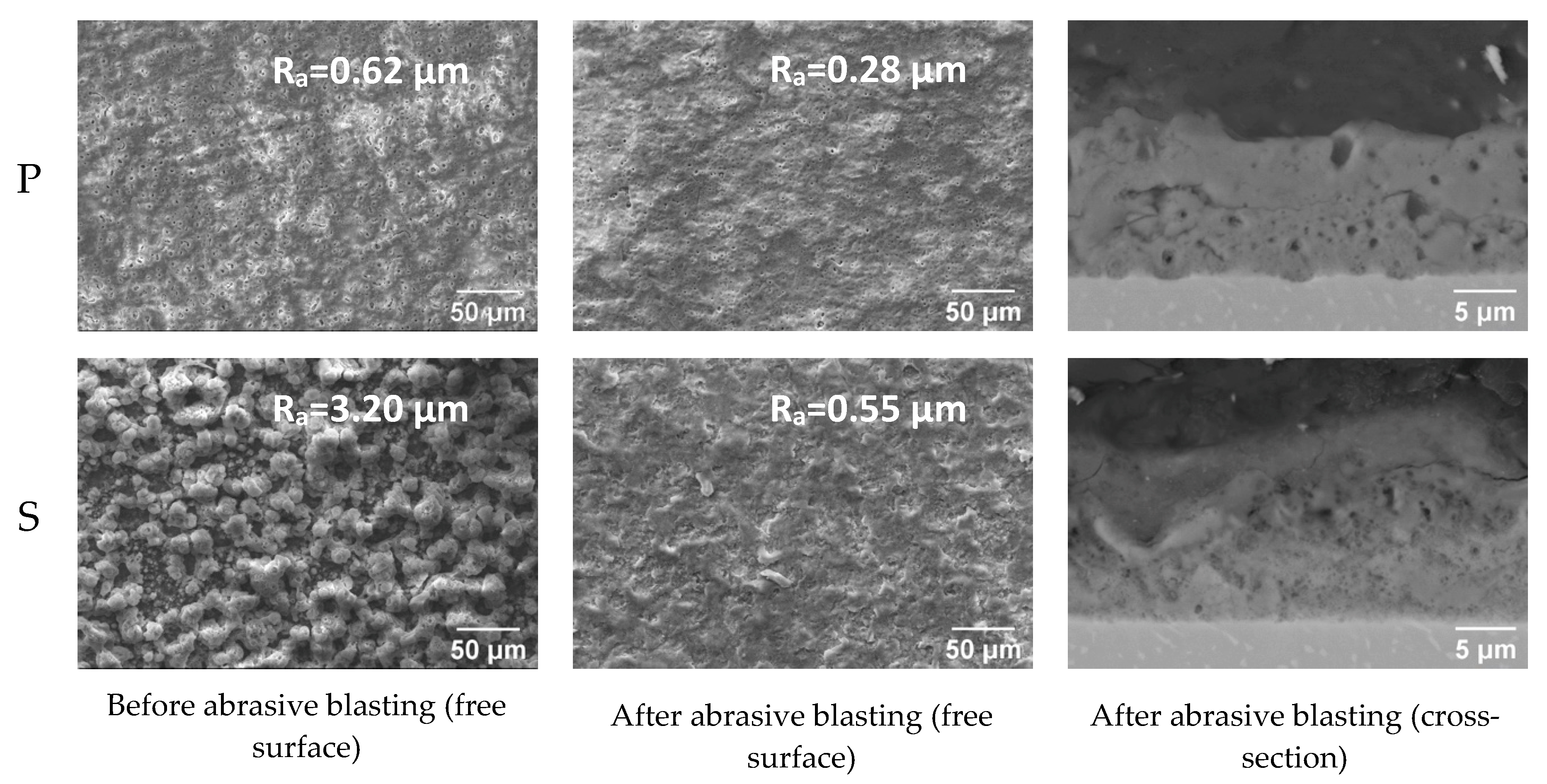
3.2. Influence of Abrasive Blasting
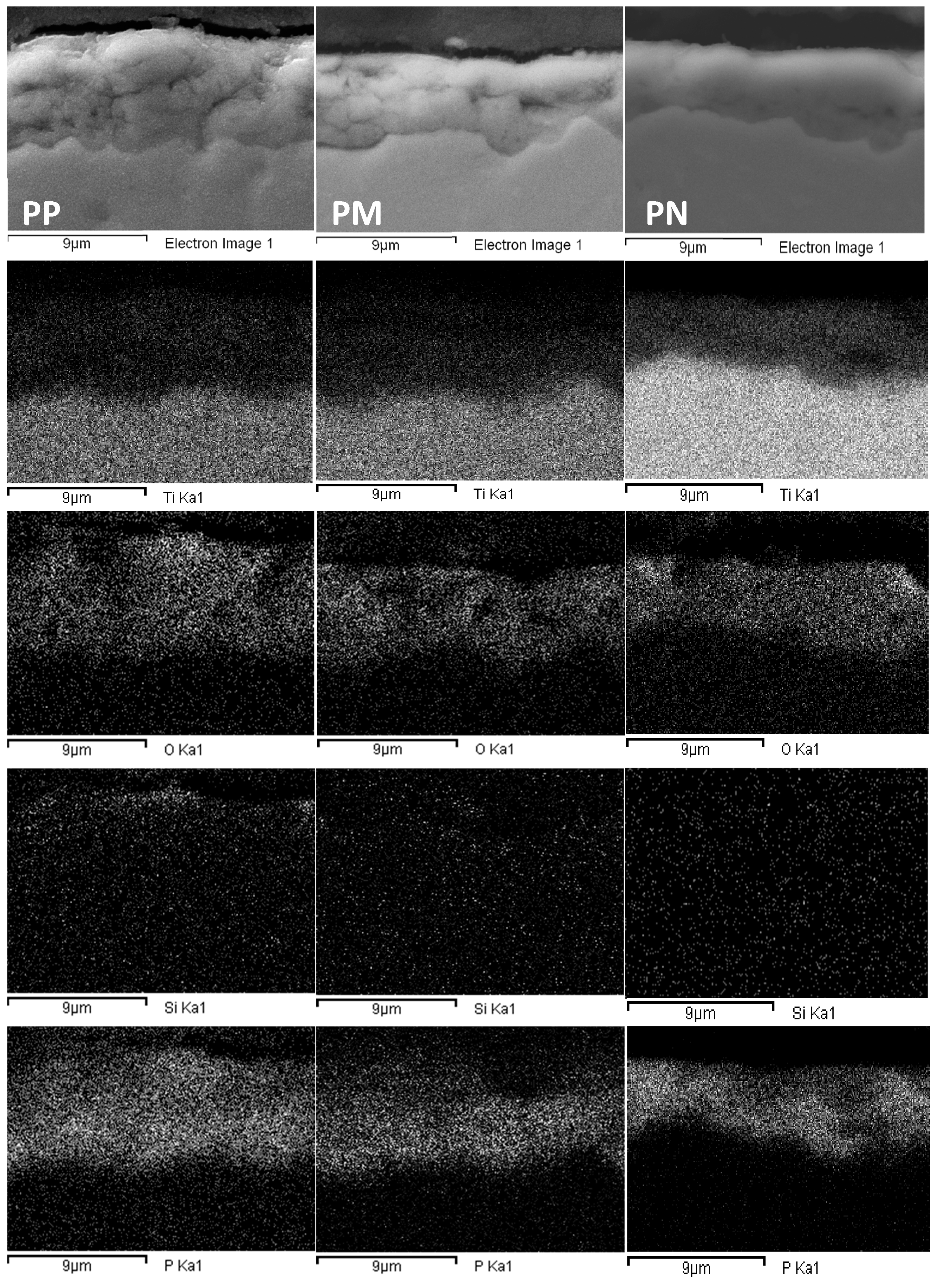
3.3. Influence of Current Mode (DC Versus Pulsed DC)
3.4. Influence of Duty Cycle (Pulsed DC)
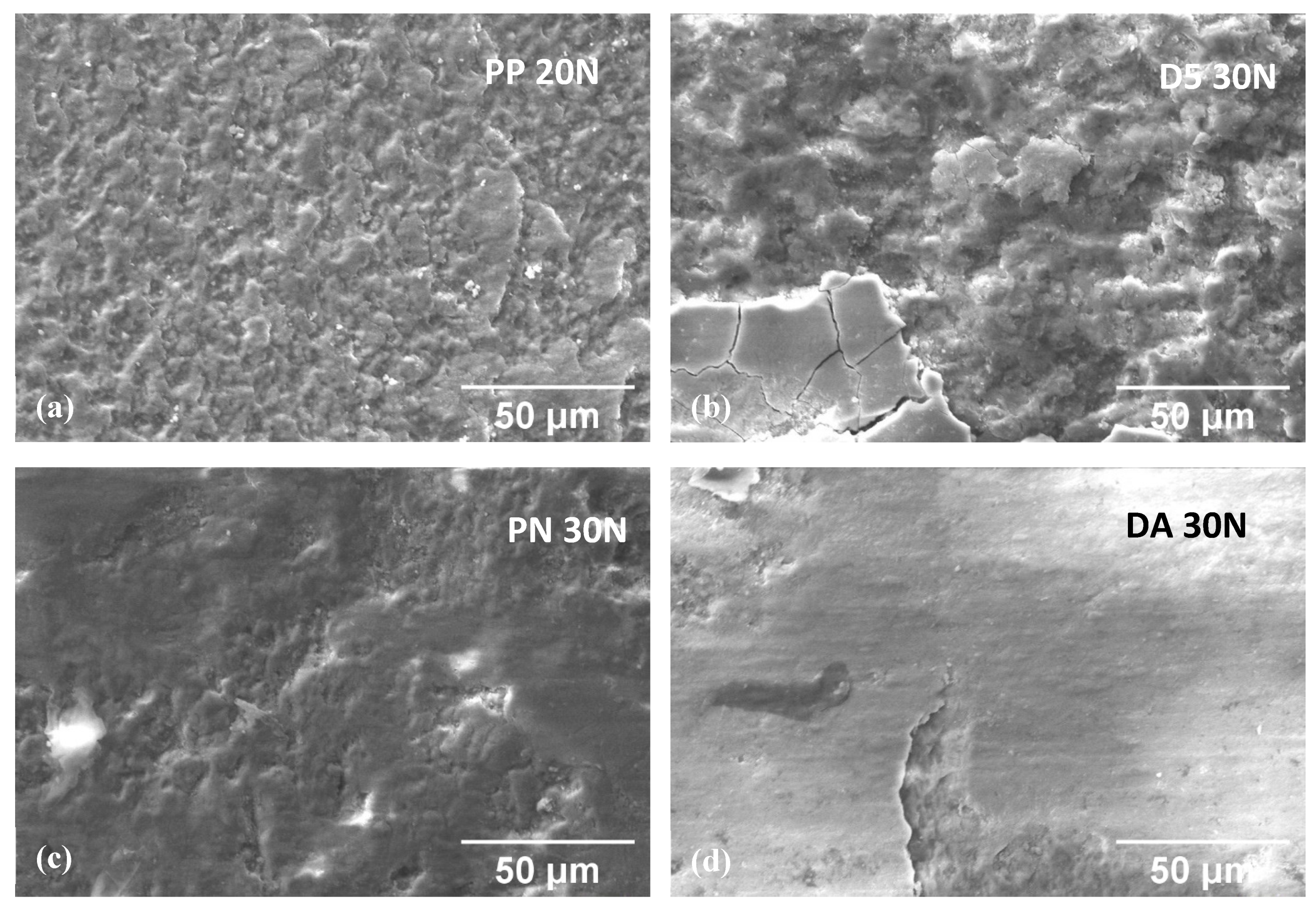
3.5. Dry Sliding Tests
4. Conclusions
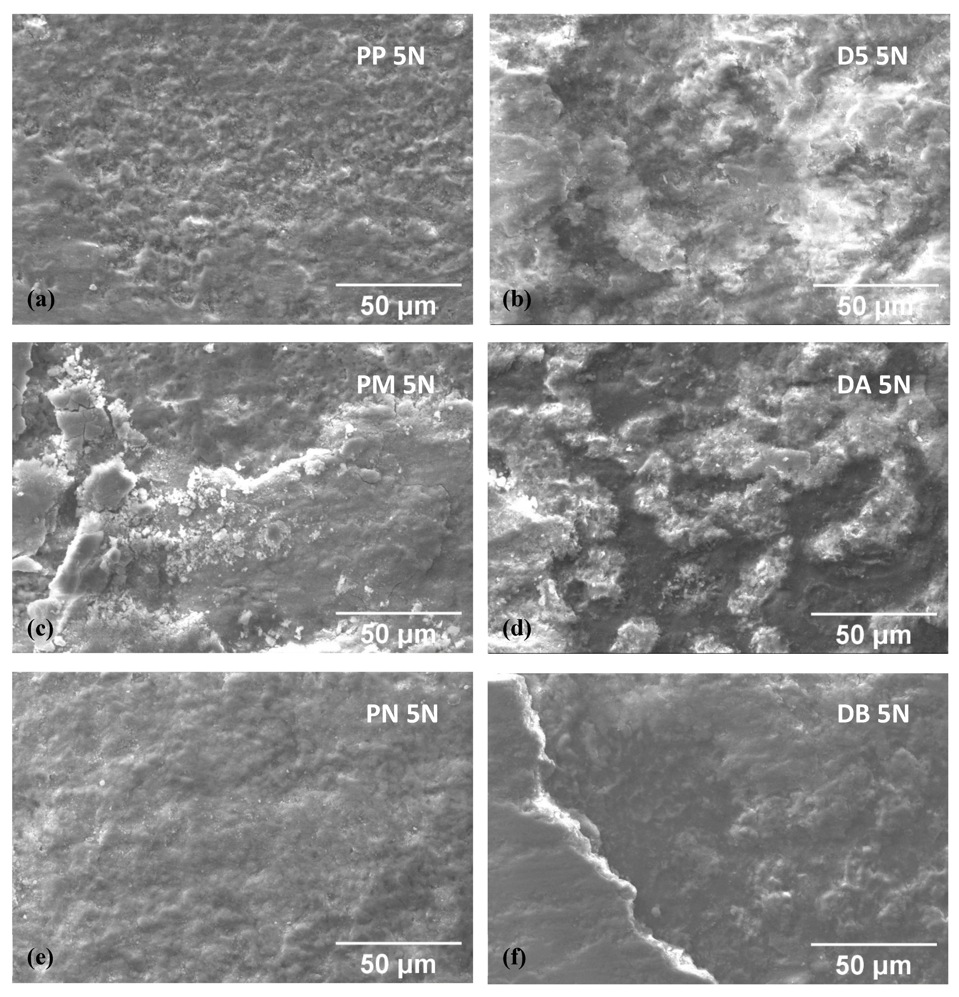
- Surface finishing by abrasive blasting with spheroidal glass beads leads to surface roughness decrease and hence to decreased friction and improved wear resistance. However, this procedure may also induce embedding of glass residues in the cortical zone of PEO layers, with an additional beneficial influence on tribological behaviour.
- The tribological behaviour of PEO layers obtained in pulsed DC tends to improve with increasing duty cycle values, due to improved microstructure and adhesion of PEO layers.
- Single-layer, high duty cycle, pulsed DC can be considered as an alternative, simpler processing route than double-layer deposition, leading to comparable wear performance.
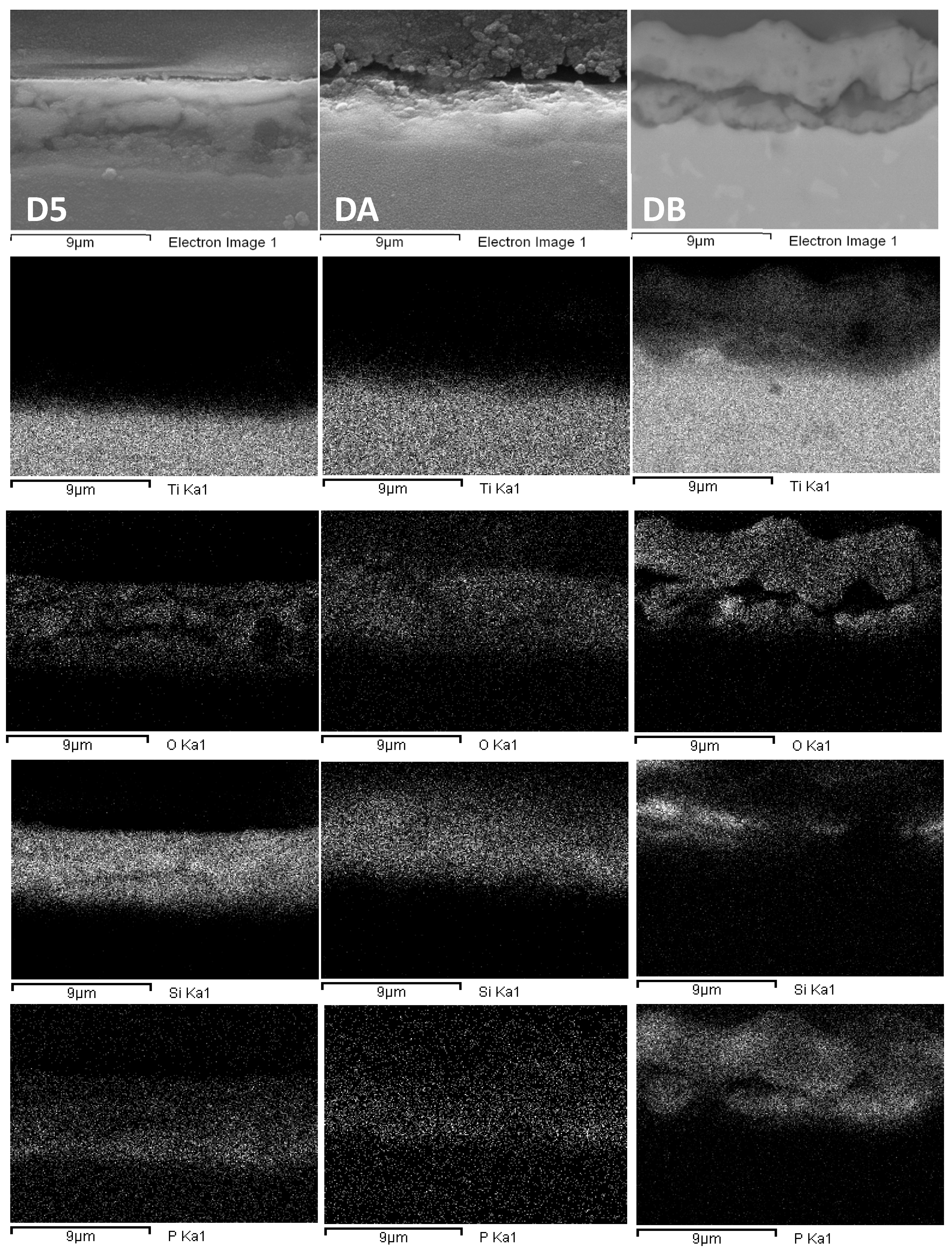
- In the case of PEO layers obtained in the conventional DC regime, the double-layer structure (treatment in silicate bath followed by phosphate bath) beneficially affected wear behaviour.
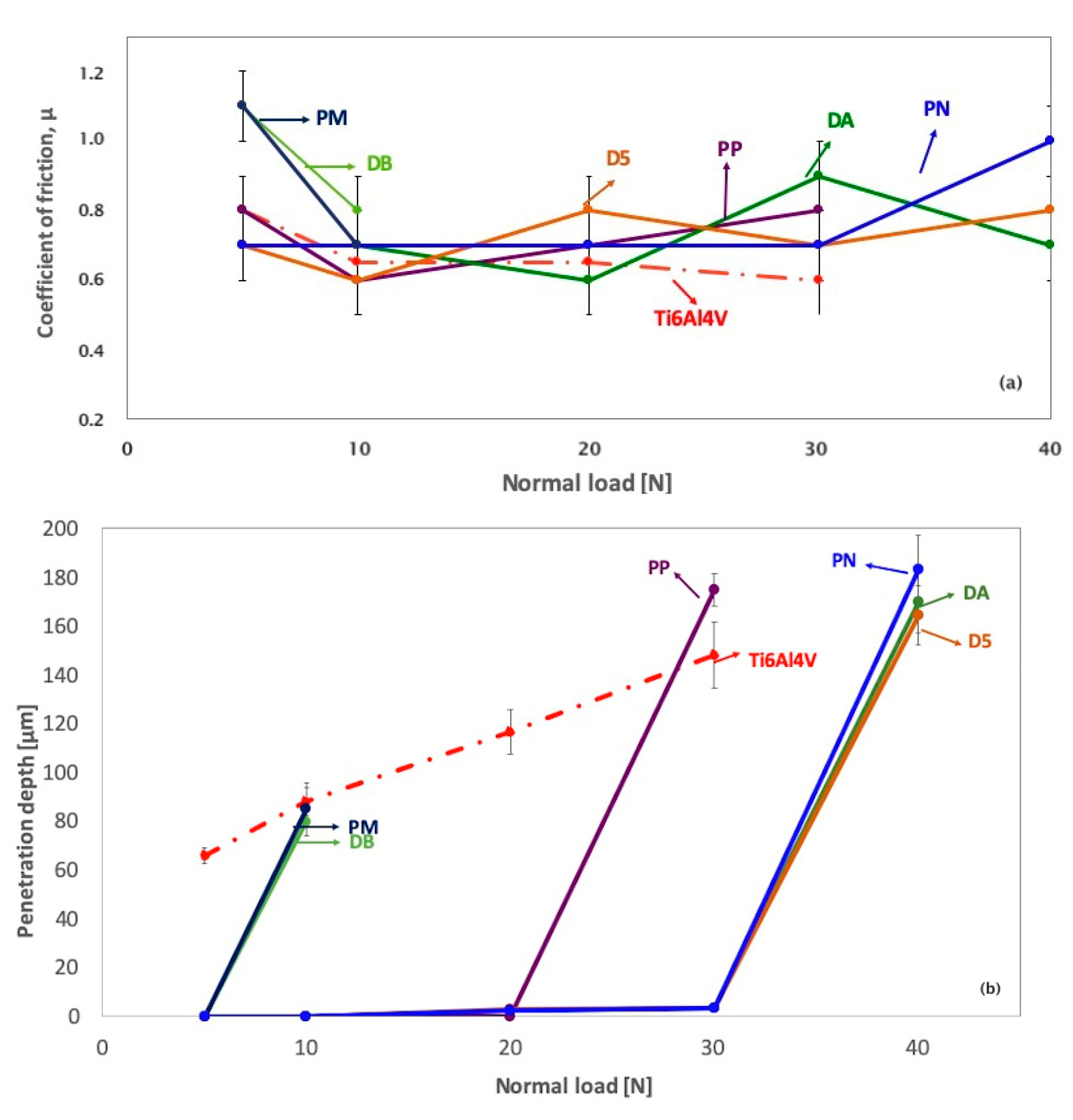
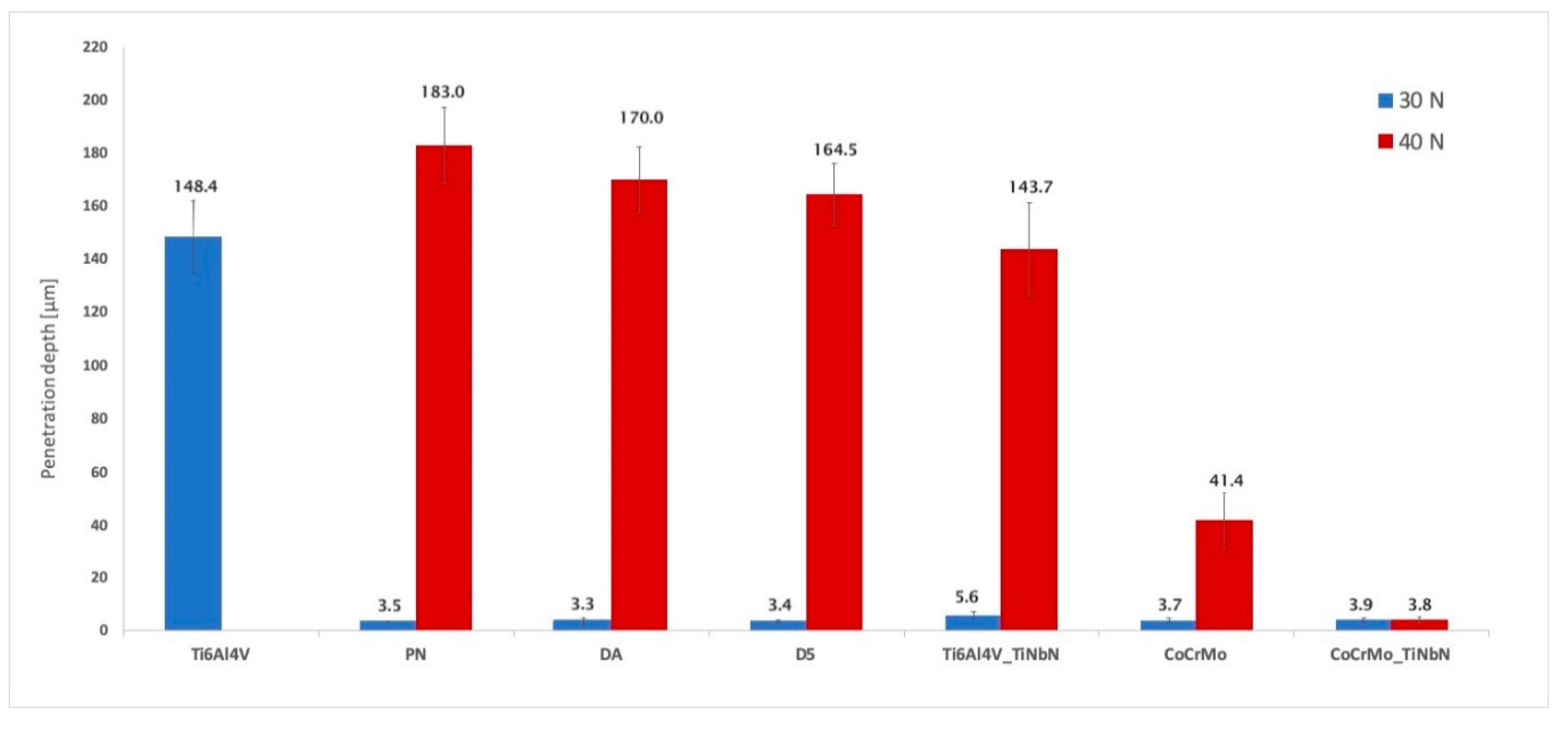
- The best PEO layers among those developed in this study showed promising results in the comparison with reference materials. In particular, at 30 N normal load, PEO layers displayed wear depths comparable to CoCrMo (both uncoated and (Ti,Nb)N PVD-coated) and slightly lower than PVD-coated Ti-6Al-4V. At 40 N, however, both PEO layers and PVD coatings on Ti-6Al-4V underwent failure and only PVD-coated CoCrMo showed low wear depths.
Author Contributions
Funding
Acknowledgments
Conflicts of Interest
References
- Chen, Q.; Thouas, G.A. Metallic implant biomaterials. Mater. Sci. Eng. R Rep. 2015, 87, 1–57. [Google Scholar] [CrossRef]
- Jarcho, M.; Kay, J.F.; Gumaer, K.I.; Doremus, R.H.; Drobeck, H.P. Tissue, cellular and subcellular events at a bone-ceramic hydroxylapatite interface. J. Bioeng. 1977, 1, 79–92. [Google Scholar] [PubMed]
- Huang, N.; Leng, Y.X.; Ding, P.D. Surface engineered titanium alloys for biomedical devices. In Surface Engineering of Light Alloys; Woodhead Publishing: Cambridge, UK, 2010; pp. 568–602. [Google Scholar]
- Durdu, S.; Deniz, Ö.F.; Kutbay, I.; Usta, M. Characterization and formation of hydroxyapatite on Ti6Al4V coated by plasma electrolytic oxidation. J. Alloys Compd. 2013, 551, 422–429. [Google Scholar] [CrossRef]
- Li, L.H.; Kong, Y.M.; Kim, H.W.; Kim, Y.W.; Kim, H.E.; Heo, S.J.; Koak, J.Y. Improved biological performance of Ti implants due to surface modification by micro-arc oxidation. Biomaterials 2004, 25, 2867–2875. [Google Scholar] [CrossRef] [PubMed]
- Jiang, B.L.; Wang, Y.M. 5-Plasma electrolytic oxidation treatment of aluminium and titanium alloys. In Surface Engineering of Light Alloys: Aluminium, Magnesium and Titanium Alloys; Dong, H., Ed.; Woodhead publishing Limited: Cambridge, UK, 2010; pp. 110–146. ISBN 1845699459. [Google Scholar]
- Shrestha, S.; Dunn, B.D. Plasma electrolytic oxidation and anodising of aluminium alloys for spacecraft applications. In Surface Engineering of Light Alloys; Woodhead Publishing: Cambridge, UK, 2010; pp. 603–641. [Google Scholar]
- Chen, Y.; Cheng, T.; Nie, X. Wear failure behaviour of titanium-based oxide coatings on a titanium alloy under impact and sliding forces. J. Alloys Compd. 2013, 578, 336–344. [Google Scholar] [CrossRef]
- Chen, F.; Zhou, H.; Chen, C.; Xia, Y.J. Study on the tribological performance of ceramic coatings on titanium alloy surfaces obtained through microarc oxidation. Prog. Org. Coat. 2009, 64, 264–267. [Google Scholar]
- Wang, Y.M.; Jiang, B.L.; Guo, L.X.; Lei, T.Q. Tribological behavior of microarc oxidation coatings formed on titanium alloys against steel in dry and solid lubrication sliding. Appl. Surf. Sci. 2006, 252, 2989–2998. [Google Scholar] [CrossRef]
- International Standard ISO 20502. Fine Ceramics (Advanced Ceramics, Advanced Technical Ceramics)—Determination of Adhesion of Ceramic Coatings by Scratch Testing, 1st ed.; Korean Agency for Technology and Standards: Chungcheongbuk-do, Korea, 2002; Volume 6, pp. 1–16. [Google Scholar]
- ASTM Standard G77. Standard Test Method for Ranking Resistance of Materials to Sliding Wear Using Block-on-Ring Test; ASTM International: West Conshohocken, PA, USA, 2017. [Google Scholar]
- Ceschini, L.; Chiavari, C.; Marconi, A.; Martini, C. Influence of the countermaterial on the dry sliding friction and wear behaviour of low temperature carburized AISI316L steel. Tribol. Int. 2013, 67, 36–43. [Google Scholar] [CrossRef]
- Borgese, L.; Gelfi, M.; Bontempi, E.; Goudeau, P.; Geandier, G.; Thiaudière, D.; Depero, L.E. Young modulus and Poisson ratio measurements of TiO2 thin films deposited with Atomic Layer Deposition. Surf. Coat. Technol. 2012, 206, 2459–2463. [Google Scholar] [CrossRef]
- Soares, P.; Mikowski, A.; Lepienski, C.M.; Santos, E.; Soares, G.A.; Filho, V.S.; Kuromoto, N.K. Hardness and elastic modulus of TiO2 anodic films measured by instrumented indentation. J. Biomed. Mater. Res. Part B Appl. Biomater. 2008, 84, 524–530. [Google Scholar] [CrossRef]
- Galetz, M.C.; Seiferth, S.H.; Theile, B.; Glatzel, U. Potential for adhesive wear in friction couples of UHMWPE running against oxidized zirconium, titanium nitride coatings, and cobalt-chromium alloys. J. Biomed. Mater. Res. Part B Appl. Biomater. 2010, 93, 468–475. [Google Scholar] [CrossRef]
- Malchesky, P.S. Artificial Organs 2003: A Year in Review. Artif. Organs 2004, 28, 410–424. [Google Scholar] [CrossRef]
- Paschoal, A.L.; Vanâncio, E.C.; Canale, L.C.F.; Silva, O.L.; Huerta-Vilca, D.; Motheo, A.J. Metallic Biomaterials TiN-Coated: Corrosion Analysis and Biocompatibility. Artif. Organs 2003, 27, 461–464. [Google Scholar] [CrossRef]
- Standard Specification for Wrought Cobalt-28Chronium-6Molybdenum Alloys for Surgical Implants (UNS R31537, UNS R31538, and UNS R31539); ASTM F1537; ASTM International: West Conshohocken, PA, USA, 2011.
- Standard Test Methods for Determining Average Grain Size; ASTM E112; ASTM International: West Conshohocken, PA, USA, 2012.
- Bouchard, M.; Smith, D.C. Raman Spectroscopy in Archaeology and Art History; Edwards, H.G.M., Chalmers, J.M., Eds.; Royal Society of Chemistry: London, UK, 2005; pp. 429–464. ISBN 9780854045228. [Google Scholar]
- Friedemann, A.E.R.; Thiel, K.; Haßlinger, U.; Ritter, M.; Gesing, T.M.; Plagemann, P. Investigations into the structure of PEO-layers for understanding of layer formation. Appl. Surf. Sci. 2018, 443, 467–474. [Google Scholar] [CrossRef]
- Xue, W.; Deng, Z.; Lai, Y.; Chen, R. Analysis of Phase Distribution for Ceramic Coatings Formed by Microarc Oxidation on Aluminum Alloy. J. Am. Ceram. Soc. 1998, 81, 1365–1368. [Google Scholar] [CrossRef]
- Khan, R.H.U.; Yerokhin, A.L.; Li, X.; Dong, H.; Matthews, A. Influence of current density and electrolyte concentration on DC PEO titania coatings. Surf. Eng. 2014, 30, 102–108. [Google Scholar] [CrossRef]
- Martini, C.; Ceschini, L.; Tarterini, F.; Paillard, J.M.; Curran, J.A. PEO layers obtained from mixed aluminate–phosphate baths on Ti–6Al–4V: Dry sliding behaviour and influence of a PTFE topcoat. Wear 2010, 269, 747–756. [Google Scholar] [CrossRef]
- Wang, Y.; Lei, T.; Jiang, B.; Guo, L. Growth, microstructure and mechanical properties of microarc oxidation coatings on titanium alloy in phosphate-containing solution. Appl. Surf. Sci. 2004, 233, 258–267. [Google Scholar] [CrossRef]
- Yerokhin, A.L.; Nie, X.; Leyland, A.; Matthews, A. Characterisation of oxide films produced by plasma electrolytic oxidation of a Ti–6Al–4V alloy. Surf. Coat. Technol. 2000, 130, 195–206. [Google Scholar] [CrossRef]
- Wang, Y.M.; Jiang, B.L.; Lei, T.Q.; Guo, L.X. Microarc oxidation coatings formed on Ti6Al4V in Na2SiO3 system solution: Microstructure, mechanical and tribological properties. Surf. Coat. Technol. 2006, 201, 82–89. [Google Scholar] [CrossRef]
- Yeung, W.K.; Reilly, G.C.; Matthews, A.; Yerokhin, A. In vitro biological response of plasma electrolytically oxidized and plasma-sprayed hydroxyapatite coatings on Ti–6Al–4V alloy. J. Biomed. Mater. Res. B Appl. Biomater. 2013, 101, 939–949. [Google Scholar] [CrossRef]
- Mohammadi, H.; Hafezi, M.; Nezafati, N.; Heasarki, S.; Nadernezhad, A.; Ghazanfari, S.M.H.; Sepantafar, M. Bioinorganics in Bioactive Calcium Silicate Ceramics for Bone Tissue Repair: Bioactivity and Biological Properties. J. Ceram. Sci. Technol. 2014, 5, 1–12. [Google Scholar]
- Aliasghari, S.; Němcová, A.; Skeldon, P.; Thompson, G.E. Influence of coating morphology on adhesive bonding of titanium pre-treated by plasma electrolytic oxidation. Surf. Coat. Technol. 2016, 289, 101–109. [Google Scholar] [CrossRef]
- Dehnavi, V.; Luan, B.L.; Liu, X.Y.; Shoesmith, D.W.; Rohani, S. Correlation between plasma electrolytic oxidation treatment stages and coating microstructure on aluminum under unipolar pulsed DC mode. Surf. Coat. Technol. 2015, 269, 91–99. [Google Scholar] [CrossRef]
- Galvis, O.A.; Quintero, D.; Castaño, J.G.; Liu, H.; Thompson, G.E.; Skeldon, P.; Echeverría, F. Formation of grooved and porous coatings on titanium by plasma electrolytic oxidation in H2SO4/H3PO4 electrolytes and effects of coating morphology on adhesive bonding. Surf. Coat. Technol. 2015, 269, 238–249. [Google Scholar] [CrossRef]
- Diamanti, M.V.; Sebastiani, M.; Mangione, V.; Del Curto, B.; Pedeferri, M.P.; Bemporad, E.; Cigada, A.; Carassiti, F. Multi-step anodizing on Ti6Al4V components to improve tribomechanical performances. Surf. Coat. Technol. 2013, 227, 19–27. [Google Scholar] [CrossRef]
- Tekin, K.C.; Malayoglu, U.; Shrestha, S. Tribological behaviour of plasma electrolytic oxide coatings on Ti6Al4V and cp-Ti alloys. Surf. Eng. 2016, 32, 435–442. [Google Scholar] [CrossRef]
- Durdu, S.; Usta, M. The tribological properties of bioceramic coatings produced on Ti6Al4V alloy by plasma electrolytic oxidation. Ceram. Int. 2014, 40, 3627–3635. [Google Scholar] [CrossRef]
- Curran, J.A.; Clyne, T.W. Porosity in plasma electrolytic oxide coatings. Acta Mater. 2006, 54, 1985–1993. [Google Scholar] [CrossRef]
- Tonelli, L.; Pezzato, L.; Dolcet, P.; Dabalà, M.; Martini, C. Effects of graphite nano-particle additions on dry sliding behaviour of plasma-electrolytic-oxidation-treated EV31A magnesium alloy against steel in air. Wear 2018, 404, 122–132. [Google Scholar] [CrossRef]


| Layer(s) | Current Mode | Current Density (mA cm−2) | Deposition Time (s) | Duty Cycle (%) | Post-Treatment | |
|---|---|---|---|---|---|---|
| P | phosphate | DC | 30 | 600 | - | abrasive blasting |
| S | silicate | DC | 70 | 600 | - | abrasive blasting |
| PP | phosphate | Pulsed DC | 30 | 600 | 60 | abrasive blasting |
| PM | phosphate | Pulsed DC | 30 | 600 | 72 | abrasive blasting |
| PN | phosphate | Pulsed DC | 30 | 600 | 80 | abrasive blasting |
| D5 | internal: silicate | DC | 70 | 300 | - | abrasive blasting |
| external: phosphate | 70 | 300 | - | |||
| DA | internal: silicate | Pulsed DC | 30 | 600 | 25 | abrasive blasting |
| external: phosphate | 30 | 600 | 68 | |||
| DB | internal: silicate | Pulsed DC | 30 | 600 | 25 | none |
| external: phosphate | 30 | 600 | 68 |
| Title | Layer (s) | Phase Composition, XRD | Surface Roughness Ra (μm) | Thickness (μm) | Hardness (HK0.025) | Lc3 (N) | Load to Failure in Dry Sliding (N) | ||
|---|---|---|---|---|---|---|---|---|---|
| Anatase (TiO2) | Rutile (TiO2) | Aluminium Phosphate (AlPO4) | |||||||
| P | single | ++ | + | - | 0.28 ± 0.06 | 12.8 ± 1.6 | 380 ± 26 | 12 ± 3 | 20 |
| S | single | ++ | + | - | 0.55 ± 0.04 | 15.2 ± 0.4 | 410 ± 35 | 14 ± 2 | 30 |
| PP | single | ++ | - | + | 0.34 ± 0.06 | 7.2 ± 0.8 | 400 ± 169 | 10 ± 6 | 30 |
| PM | single | ++ | - | + | 0.48 ± 0.02 | 6.5 ± 0.9 | 356 ± 170 | 15 ± 1 | 10 |
| PN | single | ++ | + | + | 0.48 ± 0.10 | 5.1 ± 1.1 | 390 ± 135 | 25 ± 1 | 40 |
| D5 | double | ++ | + | ++ | 0.68 ± 0.04 | 6.7 ± 1.0 | 467 ± 71 | 16 ± 2 | 40 |
| DA | double | ++ | + | + | 0.65 ± 0.02 | 5.4 ± 1.9 | 352 ± 126 | 21 ± 5 | 40 |
| DB | double | + | - | + | 0.98 ± 0.06 | 10.9 ± 7.2 | 290 ± 108 | 13 ± 1 | 10 |
| Title | Title | O | Ti | Al | V | Na | K | Si | P |
|---|---|---|---|---|---|---|---|---|---|
| P | Before a.b. | 48.3 ± 0.9 | 40.1 ± 0.1 | 2.4 ± 0.1 | 0.8 ± 0.2 | 0.4 ± 0.1 | - | 0.2 ± 0.1 | 7.8 ± 0.1 |
| After a.b. | 47.8 ± 0.8 | 39.5 ± 0.5 | 2.5 ± 0.1 | 1.3 ± 0.1 | 0.5 ± 0.1 | - | 0.4 ± 0.1 | 8.0 ± 0.1 | |
| S | Before a.b. | 58.3 ± 0.4 | 8.4 ± 0.3 | 0.3 ± 0.1 | 0.4 ± 0.1 | 0.7 ± 0.1 | 0.6 ± 0.1 | 27.9 ± 0.7 | 3.4 ± 0.1 |
| After a.b. | 56.6 ± 0.6 | 22.9 ± 0.4 | 1.4 ± 0.1 | 0.9 ± 0.1 | 0.5 ± 0.1 | 0.3 ± 0.1 | 15.0 ± 0.1 | 2.4 ± 0.1 |
© 2019 by the authors. Licensee MDPI, Basel, Switzerland. This article is an open access article distributed under the terms and conditions of the Creative Commons Attribution (CC BY) license (http://creativecommons.org/licenses/by/4.0/).
Share and Cite
Bertuccioli, C.; Garzoni, A.; Martini, C.; Morri, A.; Rondelli, G. Plasma Electrolytic Oxidation (PEO) Layers from Silicate/Phosphate Baths on Ti-6Al-4V for Biomedical Components: Influence of Deposition Conditions and Surface Finishing on Dry Sliding Behaviour. Coatings 2019, 9, 614. https://doi.org/10.3390/coatings9100614
Bertuccioli C, Garzoni A, Martini C, Morri A, Rondelli G. Plasma Electrolytic Oxidation (PEO) Layers from Silicate/Phosphate Baths on Ti-6Al-4V for Biomedical Components: Influence of Deposition Conditions and Surface Finishing on Dry Sliding Behaviour. Coatings. 2019; 9(10):614. https://doi.org/10.3390/coatings9100614
Chicago/Turabian StyleBertuccioli, Chiara, Andrea Garzoni, Carla Martini, Alessandro Morri, and Gianni Rondelli. 2019. "Plasma Electrolytic Oxidation (PEO) Layers from Silicate/Phosphate Baths on Ti-6Al-4V for Biomedical Components: Influence of Deposition Conditions and Surface Finishing on Dry Sliding Behaviour" Coatings 9, no. 10: 614. https://doi.org/10.3390/coatings9100614
APA StyleBertuccioli, C., Garzoni, A., Martini, C., Morri, A., & Rondelli, G. (2019). Plasma Electrolytic Oxidation (PEO) Layers from Silicate/Phosphate Baths on Ti-6Al-4V for Biomedical Components: Influence of Deposition Conditions and Surface Finishing on Dry Sliding Behaviour. Coatings, 9(10), 614. https://doi.org/10.3390/coatings9100614