Article

YAlO3—A Novel Environmental Barrier Coating for Al2O3/Al2O3–Ceramic Matrix Composites

Forschungszentrum Jülich GmbH, Institute of Energy and Climate Research, Materials Synthesis and Processing (IEK-1), 52425 Jülich, Germany
*
Author to whom correspondence should be addressed.
Coatings 2019, 9(10), 609; https://doi.org/10.3390/coatings9100609
Submission received: 30 August 2019 / Revised: 19 September 2019 / Accepted: 23 September 2019 / Published: 25 September 2019
(This article belongs to the Special Issue Environmental Barrier Coatings)

Abstract

:
Ceramic matrix composites (CMCs) are promising materials for high-temperature applications. Environmental barrier coatings (EBCs) are needed to protect the components against water vapor attack. A new potential EBC material, YAlO3, was studied in this paper. Different plasma-spraying techniques were used for the production of coatings on an alumina-based CMC, such as atmospheric plasma spraying (APS) and very low pressure plasma spraying (VLPPS). No bond coats or surface treatments were applied. The performance was tested by pull–adhesion tests, burner rig tests, and calcium-magnesium-aluminum-silicate (CMAS) corrosion tests. The samples were subsequently analyzed by means of X-ray diffraction, scanning electron microscopy, and energy-dispersive X-ray spectroscopy. Special attention was paid to the interaction at the interface between coating and substrate. The results show that fully crystalline and good adherent YAlO3 coatings can be produced without further substrate preparation such as surface pretreatment or bond coat application. The formation of a thin reaction layer between coating and substrate seems to promote adhesion.

1. Introduction

The efficiency of a gas turbine is determined by its pressure ratio and its maximum service temperature. A way to increase the efficiency is to increase the maximum temperature. However, the maximum service temperature is limited by the physical and chemical stability of the components in the high-temperature section. A significant temperature increase was achieved by the use of single-crystal super alloys, thermal barrier coatings, and complex cooling systems. Unfortunately, the complex cooling of the components leads to high efficiency losses. Therefore, there is a need for new high-temperature materials with higher temperature capabilities, so that the cooling of the components can be reduced or even omitted [1,2].
Ceramics, such as SiC and Al2O3, offer high temperature and chemical stability and therefore are promising materials for high-temperature applications. Reinforcing of the ceramic matrix with ceramic fibers avoids catastrophic failure due to crack deflection and bridging mechanisms and leads to a pseudo-plastic failure behavior of the ceramic material [3]. These so-called ceramic matrix composites (CMCs) combine high chemical and thermal stability with moderate creep rates and high strength. Among the CMCs, those based on SiC and Al2O3 are most common. Compared to SiC, Al2O3 offers higher resistance against oxidation and corrosion [3]. For this reason, an alumina-based CMC was chosen in this study.
Nevertheless, at temperatures above 1200 °C, the water vapor in the combustion atmosphere causes corrosion reactions and the formation of volatile hydroxides. Environmental barrier coatings (EBCs) are needed to protect the material from degradation [4].
Al 2 O 3   ( s ) + 3 H 2 O   ( g ) 2 Al ( OH ) 3   ( g )
An EBC should have a high resistance against water vapor at elevated temperatures; therefore, the corrosion rates of many materials were studied in the past (see Fritsch et al. [5,6,7,8], Herrmann et al. [9]). Besides the corrosion resistance, the coefficient of thermal expansion (CTE) is a crucial parameter for the performance of an EBC. Large CTE differences between substrate and EBC cause stresses during heating and cooling and may lead to premature failure. Therefore, different materials were categorized according to their corrosion rates and their CTE and presented in Figure 1. For better orientation, data for SiC/SiC and Al2O3/Al2O3 CMCs were added. It can be seen from Figure 1 that different CMCs require different type of coatings. Rare-earth disilicides are promising coating candidates for SiC/SiC composites [10,11], while rare-earth monosilicides and yttrium aluminates are potential EBC candidates for Al2O3/Al2O3 CMCs.
Some of these materials have been studied as potential EBC for oxide/oxide CMCs. Among these materials, yttria-stabilized zirconia (YSZ) coatings have been intensively investigated, since YSZ is the material of choice for thermal barrier coatings (TBCs). The suitability of plasma-sprayed, sputtered, and electron-beam physical vapor deposition (EB-PVD) YSZ coatings on wound highly porous oxide (WHIPOX) [12] has been studied by Braue et al. and Mechnich et al. [13,14,15]. To increase the bonding between substrate and coating, a reaction-bonded alumina (RBAO) [16] bond coat had to be used. Because of the CTE difference between CMC and YSZ, the coating adhesion was quite weak. Furthermore, it has been reported by Vassen et al. [17] that mechanical treatment of CMCs can cause severe damage to the matrix or even its failure.
Mechnich et al. [19] studied the adhesion of atmospheric plasma-sprayed (APS) Y2O3 coatings on WHIPOX substrates that were previously coated with an RBAO bond coat. The coating adhesion was tested by furnace cycling tests at 1200 °C. The results showed a good adhesion and no failure after 500 cycles. SEM investigations revealed the formation of yttrium aluminates at the coating–substrate interface. The formation of this reaction layer is believed to result in a good coating performance.
Atmospheric plasma-sprayed Gd2Zr2O7 coatings on an Al2O3-based CMC has been studied by Gatzen et al. [20]. Pull adhesion tests showed weak adhesion of Gd2Zr2O7 coatings on substrates without pretreatment, while the coating adhesion on laser-structured substrates was significantly increased.
Gerendas et al. [21] published a study on the performance of several APS-coated systems (YSZ, spinel, YSZ/silicate, mullite/silicate) on different oxide/oxide CMCs (UMOXTM, WHIPOXTM, OXIPOLTM (Oxidic CMC based on Polymers)). All substrates were sandblasted before coating application, and in the case of WHIPOX, an RBAO bond coat was additionally applied. The coating performance was tested with burner rig tests, and the results suggested a strong dependence of adhesion on the used CMC material.
All of the above-mentioned coating strategies involve surface preparation by sandblasting, laser structuring, or even the application of a bond coat. Furthermore, the used coatings offer only moderate corrosion rates, but as Figure 1 suggests, there are materials with corrosion rates one or two orders of magnitude lower and with more suitable CTEs. An example is YAlO3 (YAP, yttrium aluminum perovskite), which has a very low corrosion rate and a CTE close to that of the used CMC material. Because of the great chemical similarity of YAlO3 and Y2O3 and according to the phase diagram [22], a reaction layer may be formed at the interface (Y3Al5O12, YAG, yttrium aluminum garnet). Studies on Y2O3 coatings [19] have shown that this reaction layer is very beneficial for coating adhesion. Therefore, coatings with good adhesion and long service life are expected. However, there are no studies yet on the suitability of YAlO3 either as TBC or as EBC.
In the past, the production of plasma-sprayed yttrium aluminate coatings (YAG, Y3Al5O12) proved to be particularly challenging [23]. The challenging behavior of Y3Al5O12 may also be relevant for YAlO3 coatings. Nevertheless, YAlO3 is a promising EBC candidate. Therefore, plasma-sprayed YAlO3 coatings as EBC for an Al2O3-based CMC will be discussed in this study, paying special attention to the phase evolution during plasma spraying.
Because of the expected chemical bonding between coating and substrate, which is believed to cause good coating adhesion and to minimize the processing effort, no additional bond coat or surface treatment was used in this study. The coating adhesion of the plasma-sprayed coatings was studied by means of pull–adhesion tests (PAT) and thermal cycling tests. Furthermore, the resistance of the YAlO3 coatings against CMAS corrosion was tested.

2. Materials and Methods

The CMC used for this study was the commercially available material FW12 (Pritzkow Spezialkeramik, Filderstadt, Germany), consisting of alumina fibers (Nextel 610) that are embedded in a porous matrix of 85% alumina and 15% yttria-stabilized zirconia (YSZ). Before coating application, the samples were ultrasonically cleaned.
The coatings were applied by plasma spraying. The coatings were produced by means of APS and very low pressure plasma spraying (VLPPS). The coating parameters are described in Table 1. For the production of the APS coatings, an Oerlicon Metco multicoat-facility (Wohlen, Switzerland) was used, equipped with a TriplexPro-210 gun that was mounted on a six-axis robot. The VLLPS coating runs were carried out in a vacuum chamber (2 mbar), using an O3CP gun (Oerlicon Metco, Wohlen, Switzerland). The substrate temperatures during processing were measured by IR pyrometry.
In both processes, a spray-dried YAlO3 powder with a particle size of 37 µm and a purity of 96% was used. X-ray diffraction (XRD) measurements (Figure 2) revealed the presence of Y4Al2O9 and Y3Al5O12 as secondary phases.
After coating manufacturing, the samples were furnace-cycled in air for 4 × 20 h at 1200 °C. In order to assess the thermal and chemical stability of the coatings, XRD measurements were carried out before and after thermal aging. The XRD measurements were carried out with a Bruker D4 Endeavor (Karlsruhe, Germany), using Cu-Kα-radiation (λ = 1.54187 Å). Rietveld refinements were carried out using FullProf suite [24].
The coating adhesion of the as-sprayed coatings was measured with an Elcometer 510 (Aalen, Germany), according to ASTM D4541 [25]. Test dollies with a 10 mm diameter were used and glued to the sample with Araldite two-part epoxy adhesive. Furthermore, the coating performance during thermal cycling was tested by burner rig tests, using the setup described by Traeger et al. [26]. The samples were mounted in a ceramic sample holder and subjected to cycles of 5 min of heating followed by 2 min of cooling. The temperature was measured with pyrometers from the front and back sides. The used temperature program consisted of 510 cycles at 1200 °C, followed by 500 cycles at 1300 °C. The CMAS stability of the samples was tested with a special burner rig, described by Steinke et al. [27]. The surface temperature was set to 1250 °C to ensure melting of the CMAS components.
Materialographic cross sections of the samples before and after testing were prepared. For this, the samples were embedded into resin, cut, and wet-ground with successively finer abrasive paper down to a grit designation of P4000. Afterwards, the samples were polished with diamond suspensions. The polished samples were sputtered with platinum (Leica EM ACE200, Vienna, Austria) and analyzed by scanning electron microscopy (SEM) (Hitachi, TM3000, Tokyo, Japan).

3. Results and Discussion

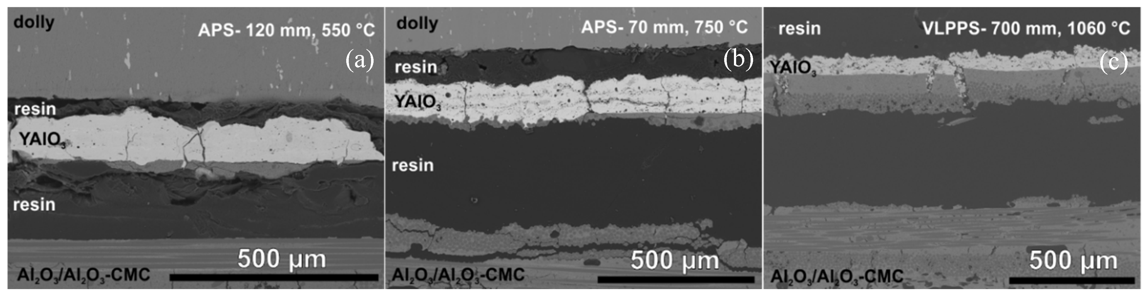
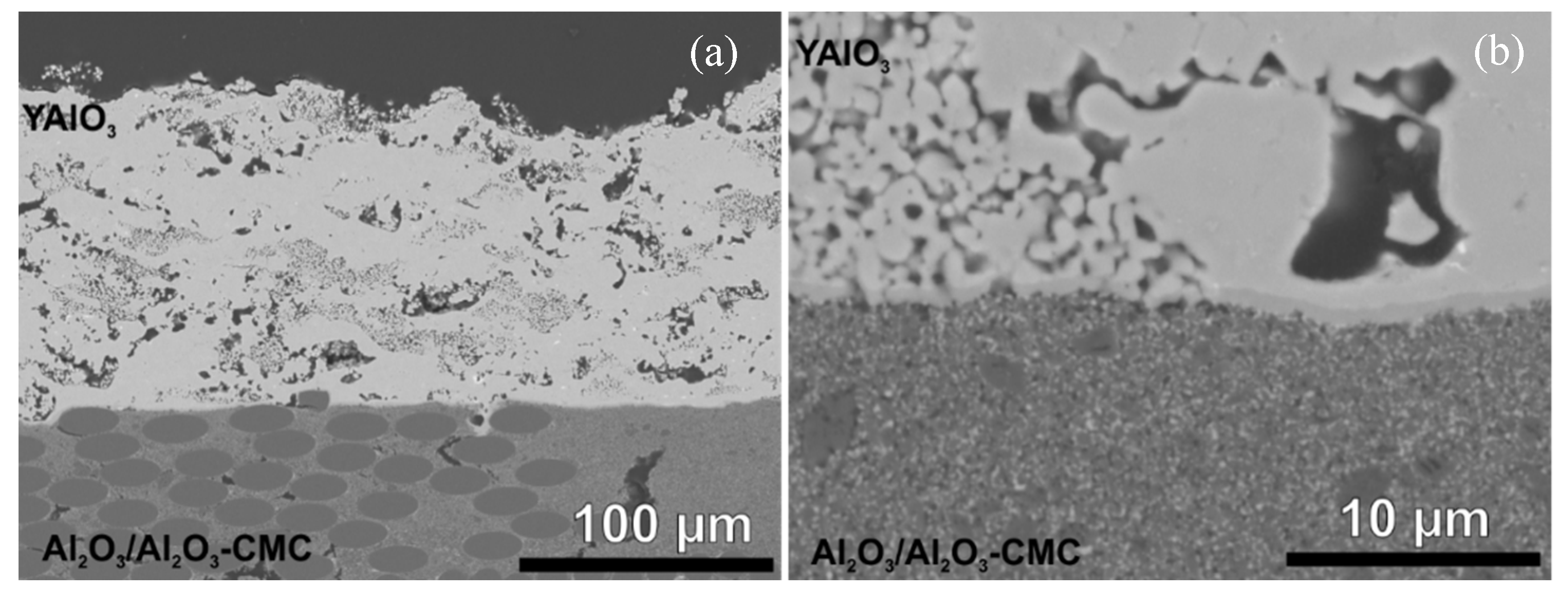
3.1. Coating Formation

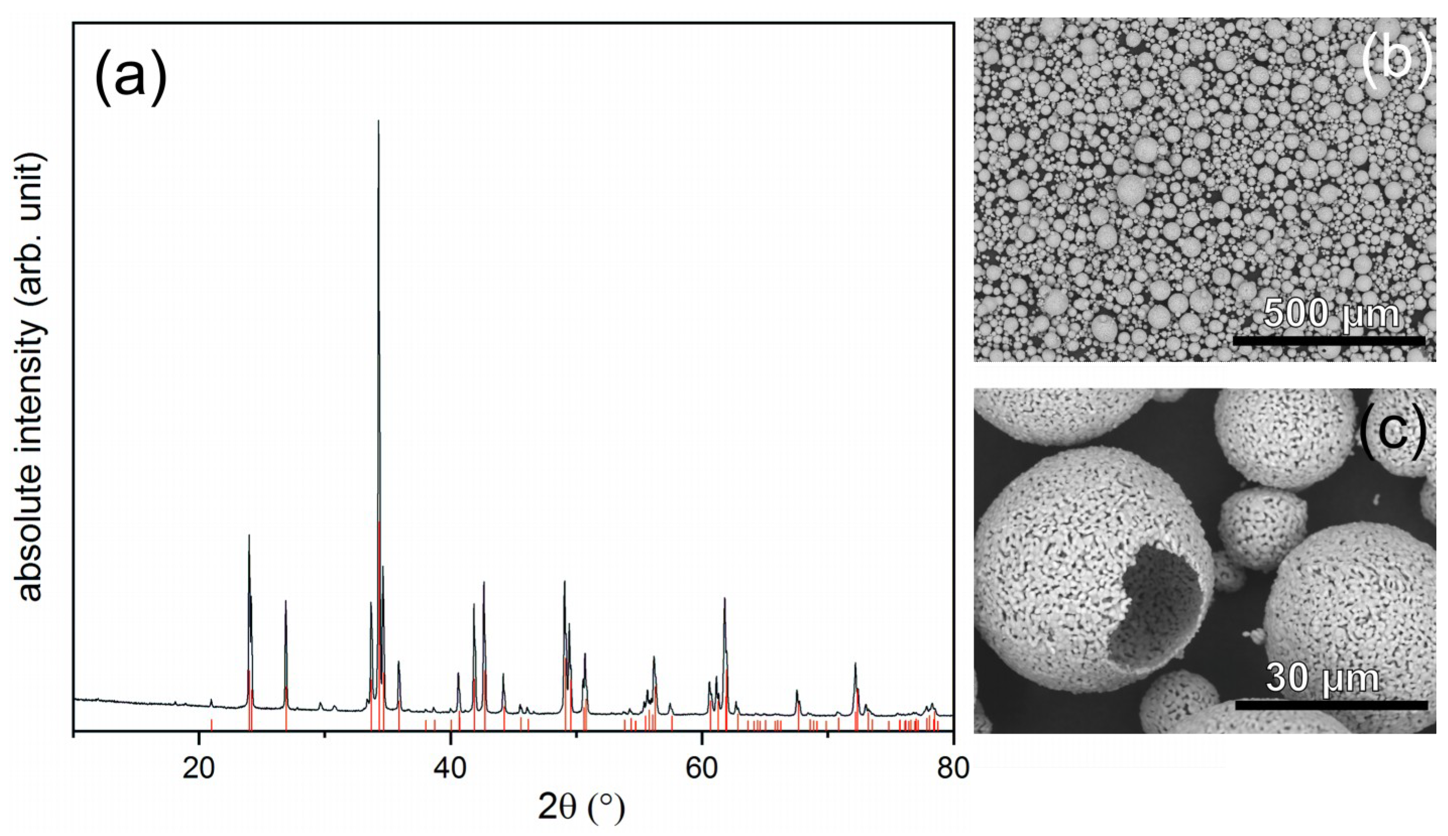
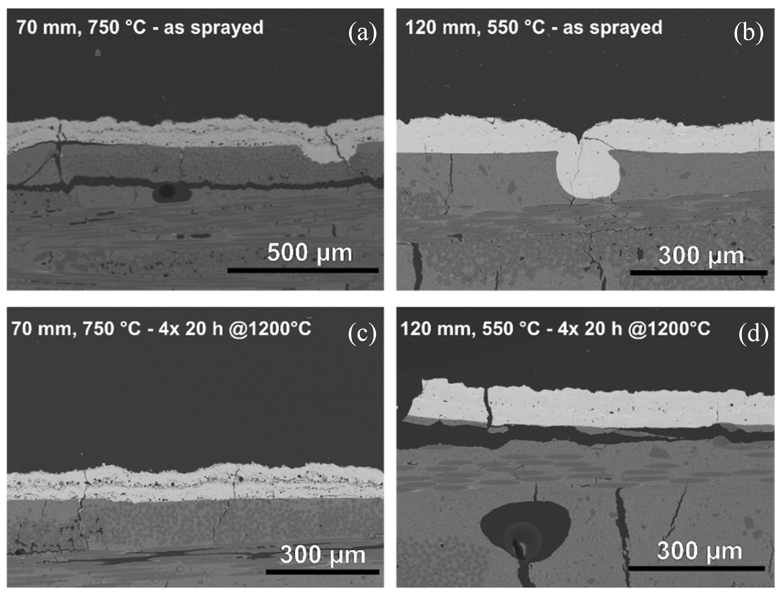
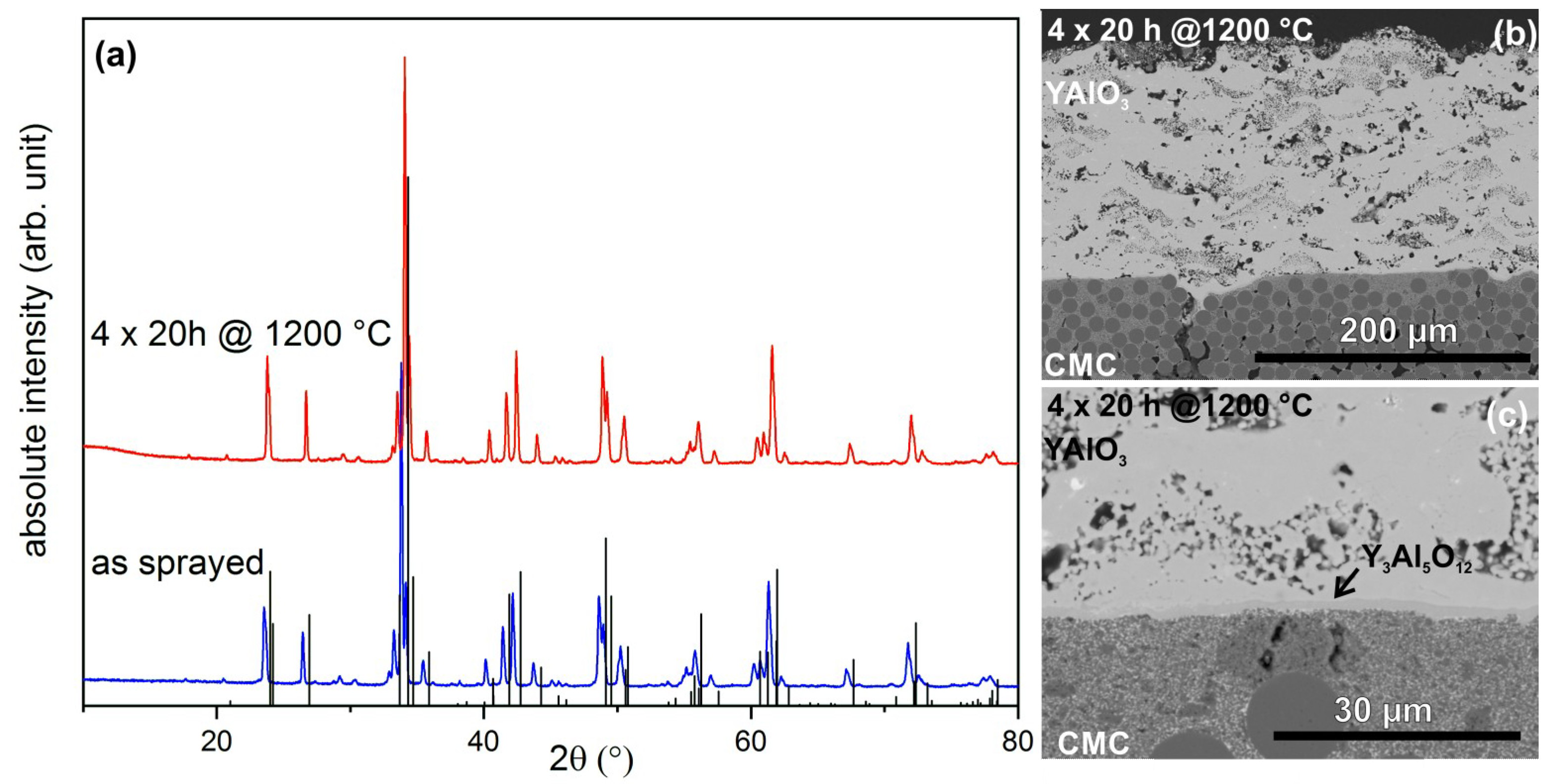
3.1.1. Atmospheric Plasma Spraying

The YAlO3 coatings were produced using APS at varying stand-off distances and resulting different coating temperatures. The XRD-measurements of the APS YAlO3 coatings before and after thermal cycling are presented in Figure 3. The coating sprayed at higher stand-off distance and thus lower substrate temperature was amorphous in the as-sprayed state. The thermal cycling led to the crystallization of the coating. Phase analysis revealed the presence of YAlO3, Y3Al5O12, and Y4Al2O9. The refined phase content of the different phases is given in Table 2. Phase analysis showed that the three yttrium aluminates occurred in almost equal fractions.
The coating sprayed at lower stand-off distance and thereby higher substrate temperature was crystalline in the as-sprayed state. The main phase was the desired YAlO3 phase, but significant amounts of Y3Al5O12 and Y4Al2O9 were present. The heat treatment led to further crystallization and phase segregation of the coating. The composition shifted in favor of the desired YAlO3 phase.
To enable crystallization of the YAlO3 coating, a certain energy level must be exceeded. Furthermore, the cooling rate should be slow, so that there is enough time for atomic rearrangement and the formation of a long-range order. The cooling rate can be lowered by using higher plasma power, by shortening the stand-off distance, or by substrate preheating. The splat solidification time [28] is a key factor. A dependence of the splat solidification time on the temperature gradient between splat and substrate has been reported [28,29]. A decreased gradient leads to a longer solidification time, consequently the splats deposited at higher temperatures have more time for crystallization. This explains why the YAlO3 coatings, sprayed at shorter distances (70 mm) and higher substrate temperatures (750 °C) were crystalline, while those sprayed at 120 mm distance and a significantly lower temperature (550 °C) were amorphous.
The formation of secondary phases can be explained by the evaporation of elements during thermal spraying, causing a shift in the phase diagram [23]. In this case, evaporation of alumina might occur, since alumina has a higher vapor pressure then yttria [30]. A more probable explanation is demixing due to rapid quenching of splats and impure base material (see Figure 2). This is supported by the fact that the coating, which was sprayed at higher distance and lower substrate temperature resulting in a larger temperature gradient between splat and substrate, differed significantly more from the desired phase composition. Furthermore, yttrium aluminates with both high alumina content and low-alumina content were found. If evaporation of alumina was the main mechanism, the phase equilibrium would be shifted to the phase with low alumina content (Y4Al2O9).
SEM images of cross sections of YAlO3 coatings before and after thermal cycling are presented in Figure 4. The amorphous coatings sprayed at higher distances (120 mm) and thus lower substrate temperatures were relatively dense and showed only few cracks. The presence of secondary phases, which was already revealed by XRD-measurements, can also be observed in the SEM images. The SEM images reveal that the coating was delaminated during thermal cycling. Coating delamination might be attributed to the occurring crystallization of the coating.
The coatings obtained at a smaller stand-off distance (70 mm) were already crystalline in the as-sprayed state. However, large pores were present in these coatings, especially at the interface between the different coating layers. Sporadic delamination was observed even in the as-sprayed state, and the coatings were prone to form segmentation cracks. Both cracks and pores have a negative effect on corrosion resistance, as they increase the permeability of the EBC to water vapor. Here, the segmentation cracks seemed to continue into the substrate, which could additionally affect the structural integrity of the material.
These results are in good agreement with the results for APS Y3Al5O12 coatings of Weyant et al. [24]. A systematic investigation of the effects of several spraying parameters on the resulting coating microstructure led to the conclusion that the used power and the stand-off distance are the determining factors. Unfortunately, increasing spraying distances led to both lower porosity and reduced crystallinity. Moreover, increased power caused increased crystallinity, but the porosity was increased as well [24]. The same behavior was found in this study for atmospheric plasma-sprayed YAlO3 coating:
The formation of pores seemed to go along with the crystallization of the as-sprayed YAlO3 phase. This can be attributed to the differences in density between melt and solid. It is assumed that the density of amorphous YAlO3 is close to that of the liquid phase, which is slightly below 4.0 g·cm−3 [31,32,33]. The density of the crystalline phase is reported to be significantly higher, at 5.35 g·cm−3 [34]. These differences lead to shrinkage during crystallization and therefore cause the formation of large pores and cracks. In the case of initially dense but amorphous coatings, the tensile stresses that occur during the crystallization processes resulting from the thermal treatment are high, and as a consequence, the coating is delaminated.
The formation of a reaction layer, as reported for Y2O3 coatings, was not observed. It is assumed that the stresses occurring in these coatings were so high that delamination occurred before the reaction could take place. Furthermore, poor wetting could also be a reason for the absence of a reaction layer.

3.1.2. Very Low Pressure Plasma Spraying

Coatings were produced with VLPPS, in order to overcome the aforementioned problems related to crystallization in the APS YAlO3 coatings. VLPPS offers high power, high temperatures and low cooling rates. The results of the VLPPS YAlO3 coatings are presented in Figure 5.
The XRD measurements showed that the YAlO3 coatings were crystalline directly after spraying. The major phase was YAlO3, and only very weak reflections of a secondary phase (yttrium aluminum monoclinic, YAM, Y4Al2O9) were visible. Due to a slight bending of the coated sample, the measured XRD signals were slightly offset from the theoretical ones. The XRD measurement of the thermally treated sample showed hardly any deviations from the original XRD. This shows that there were no phase transformations or significant crystallization processes during heating/cooling, which could cause stresses and cracks in the coating. The formation of nearly single-phase YAlO3 can be attributed to the lower cooling rate. The increased surface temperature led to an increased solidification time. Furthermore, the low chamber pressure led to significantly slower cooling rates of the coating and substrate. As a consequence, the coating had more time to crystallize. Therefore, the resulting coating had a high crystallinity and a high content of the desired YAlO3 phase. Rietveld refinements led to a phase content >88% of the desired YAlO3 phase. This represents a significant increase compared to the coatings produced under atmospheric conditions.
The SEM images of the cross sections of the VLPPS YAlO3 coatings are shown in Figure 5a. The coating had a finely distributed porosity, which was caused by not fully molten particles. The pores were distributed homogenously in the coating. In contrast to APS coatings, no vertical cracks were observed. The VLPPS YAlO3 coatings formed a reaction layer at the interface with the substrate. This reaction zone can be observed even in the as-sprayed samples (Figure 6). This implies that the energy needed for the reaction [35] was reached in these experiments. The higher temperatures might also increase the wetting of the splats and therefore increase the contact between coating and substrate, leading to the formation of a 1–2 µm-thick reaction zone. Because of the position of YAlO3 in the Y2O3–Al2O3 phase diagram [36], the formation of Y3Al5O12 is likely. In contrast to the results for the APS coatings, there was no delamination within the coating–substrate system after heat treatment. Due to the high crystallinity and the formation of chemical bonding between coating and substrate, a strong coating adhesion is expected.

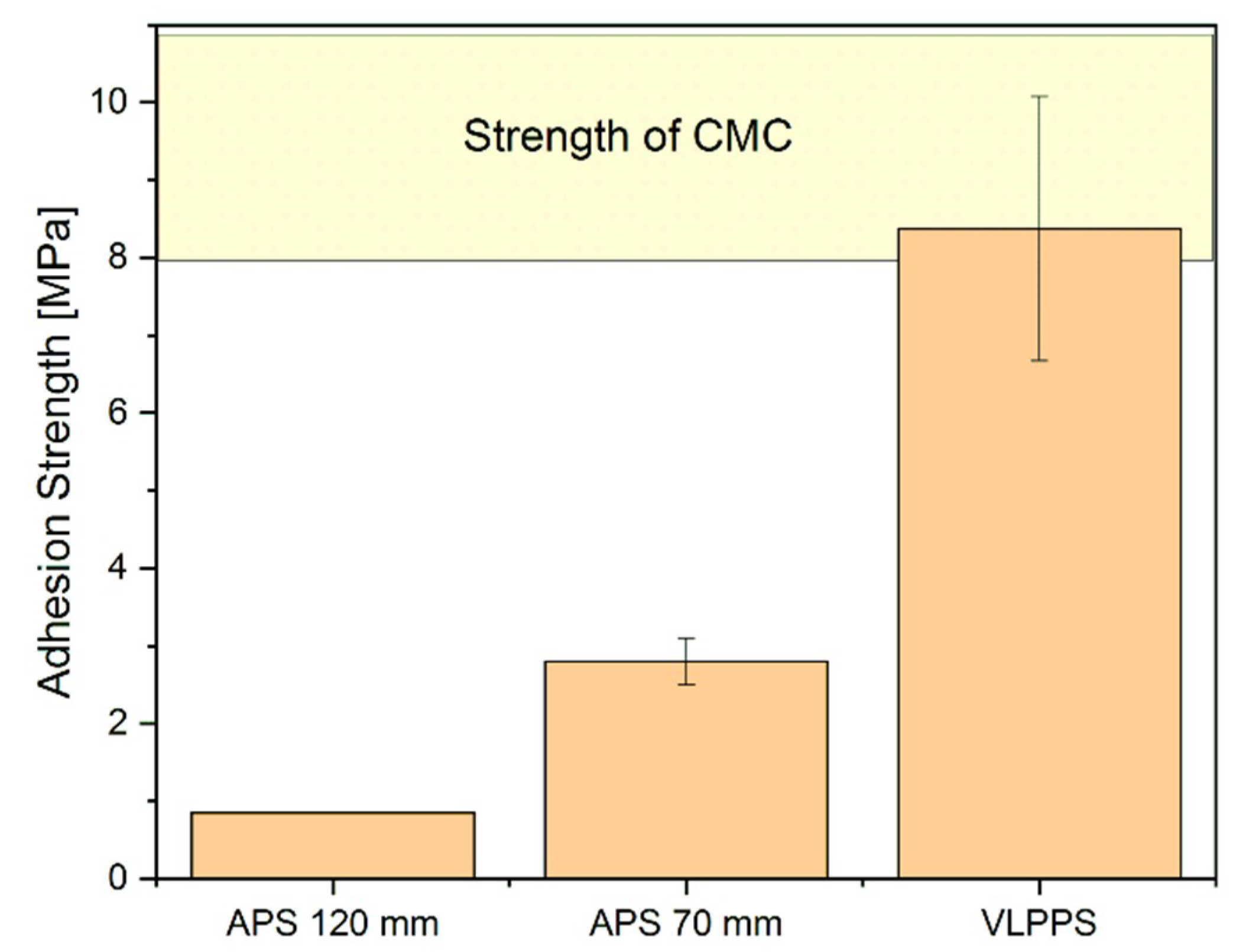
3.2. Pull–Adhesion Tests

The coating adhesion was tested with pull–adhesion tests, and the results are illustrated in Figure 7. The adhesion of the APS coatings was very poor, and both coatings failed directly at the beginning of the test. High stresses in the coatings might be the reason for the bad coating adhesion. The adhesion of the VLPPS coatings was significantly higher. The measured strength was in the order of that of the CMC itself.
The samples were embedded and cut after adhesion testing. SEM images of the polished cross sections are shown in Figure 8. The high stresses in the APS coatings led to failure partly within the CMC and partly at the coating–substrate interface. It is assumed that slight reactions between coating and substrate or clamping occurred, which caused a partial failure within the matrix of the CMC.
The good adhesion between the VLPPS coating and the CMC caused a failure deep within the substrate itself. This is consistent with the measured adhesion strength, as the measured adhesion strength was in the order of the strength of the CMC itself. The high adhesion strength was attributed to the occurrence of a chemical reaction at the coating–substrate interface.

3.3. Burner Rig Tests
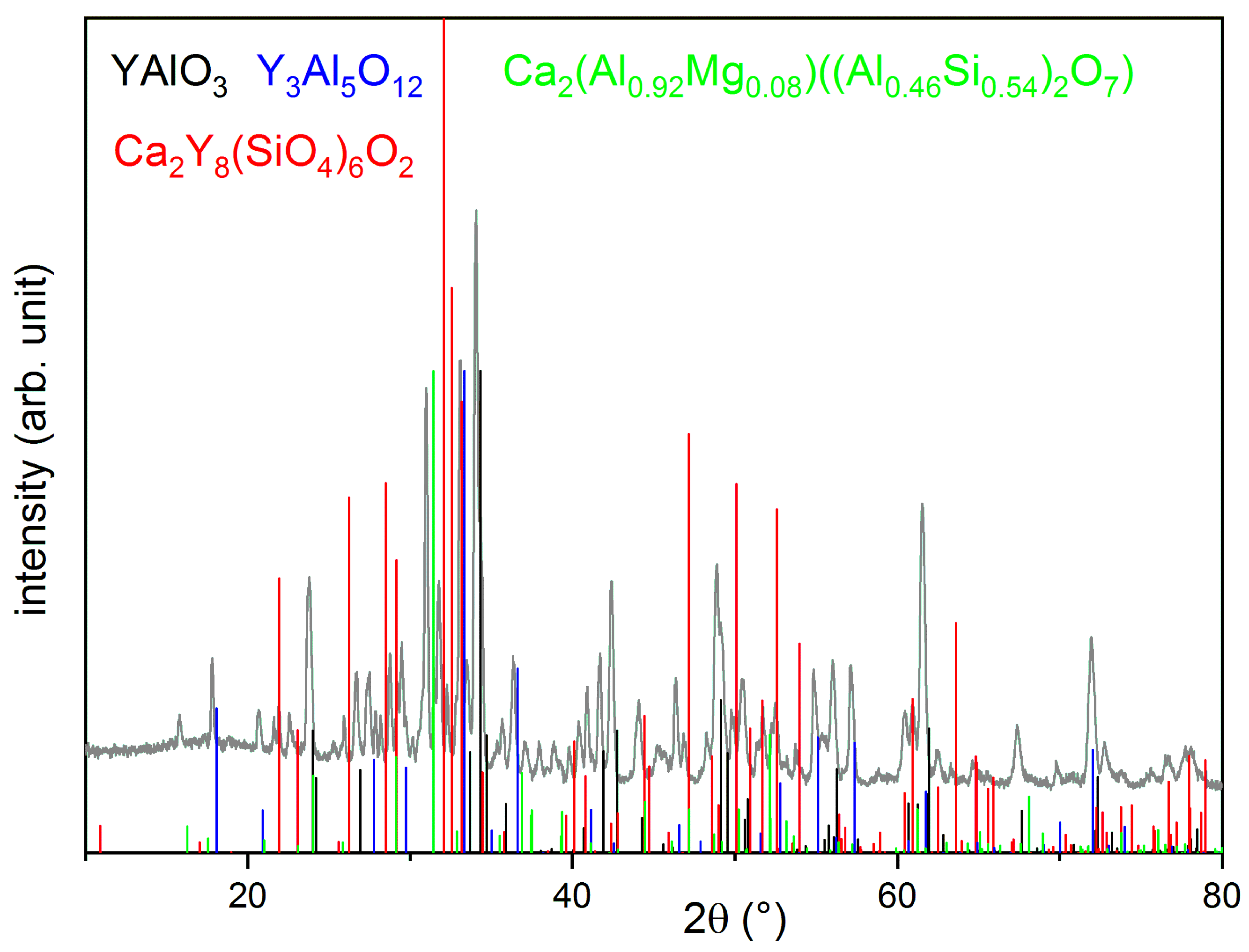
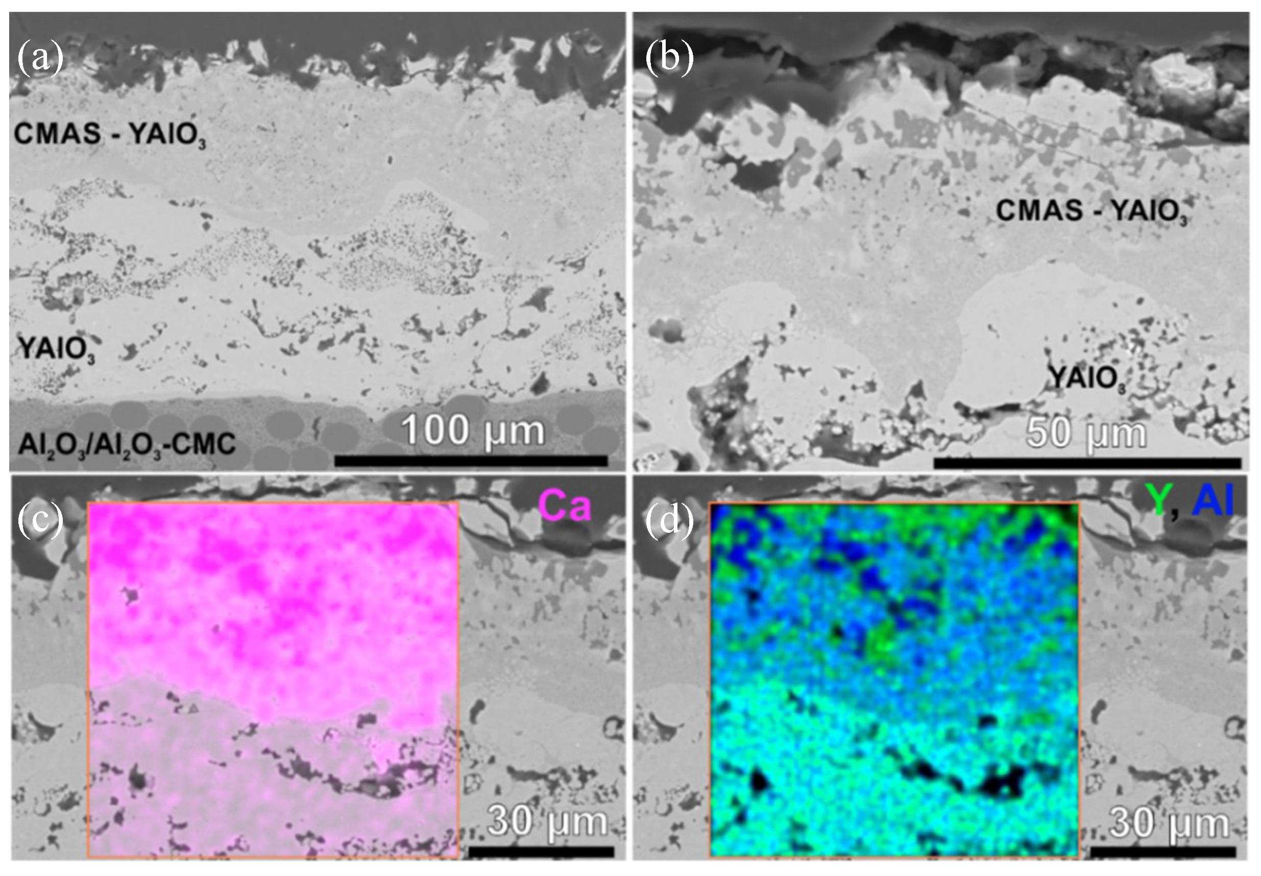
The pull–adhesion tests of the VLPPS YAlO3 coatings revealed a promising adhesion strength. On the basis of previous investigations on Y2O3 coatings resulting in excellent stability due to the formation of a reaction layer at the interface [20], a high thermal cycling lifetime of the VLPPS coatings was expected. The APS coatings showed poor adhesion strength, and as a consequence, these coatings were excluded from the following investigations.
The thermal cycling tests were stopped after 1010 cycles (510 cycles at 1200 °C and 500 cycles at 1300 °C), which corresponds to the upper limit of the average lifetime of standard TBC samples in this test rig. During cycling, no macroscopic failure occurred (see Figure 9). SEM images of the VLPPS YAlO3 coatings after 1010 cycles are shown in Figure 10. The coating still shows a fine distributed porosity. The Y3Al5O12 containing reaction zone at the coating substrate interface was about 1–2 µm-thick. No growth took place within the duration of the test.
No delamination or crack formation was observed after 1010 cycles of burner rig testing; therefore, a significantly longer lifetime can be expected. The long cycling lifetime of the YAlO3 coatings on the FW12-CMC is attributed to the strong bond between the coating and the substrate due to the formation of a thermodynamically stable reaction layer at the interface.

3.4. CMAS Tests

The coating’s resistance to CMAS corrosion was also investigated. The tests were stopped after 274 cycles, which corresponds to about twice the average lifetime of a typical YSZ coating in this rig. After 274 cycles, no macroscopic coating failure was observed (see Figure 11). The XRD measurements of the sample before and after the CMAS test are shown in Figure 12. Besides signals from the CMAS and the coating itself, the formation of calcium–yttrium silicate oxyapatite (Ca2Y8(SiO4)6O2) as a reaction product between YAlO3 and CMAS was observed. This phase was already observed for other Y-containing coatings [37,38]. In addition, the formation of Y-depleted yttrium aluminate Y3Al5O12 was observed accordingly. Turcer et al. [38] recently reported the excellent CMAS resistance of dense YAlO3 pellets due to the fast formation of a protective Ca–Y–Si apatite phase. Our results are in good agreement with those from Turcer et al.
The SEM images of the resulting cross sections are presented in Figure 13. No indications for crack formation or beginning delamination were found. Because of the porosity of the sample, the molten CMAS was able to infiltrate the upper part of the VLPPS YAlO3 coating (about 46 µm). The SEM images and the corresponding EDS measurements show the sharp borderline of the infiltrated zone. The reaction zone between CMAS and YAlO3 can be clearly seen. The CMAS infiltration and the following reactions led to densification of the infiltrated parts of the coating. The densification of the upper coating may hinder further infiltration and thus extend the lifetime of the coating. Furthermore, the CTE of the CMAS constituents is in the area of 9.7 × 10⁻⁶ K−1 [39,40] and close to the CTE of YAlO3 (8.9 × 10⁻⁶ K−1 [41]); thus, low stresses were expected during testing. Because of the remaining porosity of the lower coating parts, occurring stresses can be relaxed. As a consequence, even after 274 cycles, no spallation occurred.

4. Conclusions

The suitability of YAlO3 coatings as EBC for an Al2O3/Al2O3–CMC was examined. YAlO3 coatings were produced by means of APS and VLPPS, without applying any bond coats. Furthermore, no surface pretreatment was carried out. The APS YAlO3 coating trials resulted in coatings with either poor crystallinity or large pores, both of which are not favorable for an EBC.
YAlO3 coatings produced by VLPPS offered high crystallinity and purity. The VLPPS coatings showed strong adhesion, which was attributed to the formation of chemical bonding between coating and substrate. This thermodynamically stable reaction layer at the coating–substrate interface, probably consisting of Y3Al5O12, was found directly after spraying.
The VLPPS YAlO3 were chosen for further investigations. The thermal cycling lifetime was tested with burner rig tests. The coatings passed the test consisting of 1010 cycles without failure. Furthermore, the hot corrosion behavior was tested with CMAS tests. The coatings showed excellent CMAS resistance, by withstanding more than 274 cycles without failure. The high cycling lifetime was attributed to the densification of the coating due to CMAS infiltration and formation of a reaction product, blocking further infiltration.
The use of VLPPS for the production of YAlO3 coatings led to stable coatings with a microstructure with intermixed porous and dense zones. This led to a high thermal cycling lifetime and high CMAS resistance. Furthermore, the formation of a reaction zone at the interface enabled good coating adhesion. Therefore, VLPPS YAlO3 coatings are promising candidates for EBCs for Al2O3-based CMCs, as they offer high adhesion strength, high thermal stability, and high corrosion resistance.

Author Contributions

Conceptualization and methodology, C.G. and D.E.M.; investigation, C.G.; writing—original draft preparation, C.G.; writing—review and editing, D.E.M., R.V. and O.G.; supervision, D.E.M. and R.V.; project administration, R.V.

Funding

This research received no external funding.

Acknowledgments

The authors would like to thank Ralf Laufs, Frank Kurze, and Karl-Heinz Rauwald for their assistance during plasma spraying. The authors acknowledge Doris Sebold for the SEM analysis. In addition, tha authors would like to thank Volker Bader and Martin Tandler for the execution of the heat treatments, burner rig tests, and CMAS tests.

Conflicts of Interest

The authors declare no conflict of interest.

References

  1. Perepezko, J.H. The hotter the engine, the better. Science 2009, 326, 1068–1069. [Google Scholar] [CrossRef] [PubMed]
  2. Xin, Q. Diesel Engine System Design; Woodhead Publishing: Oxford, UK, 2013; pp. 860–908. [Google Scholar]
  3. Krenkel, W. Keramische Verbundwerkstoffe; WILEY-VCH Verlag GmbH & Co. KGaA: Weinheim, Germany, 2003. [Google Scholar]
  4. Opila, E.J.; Myers, D.L. Alumina volatility in water vapor at elevated temperatures. J. Am. Ceram. Soc. 2004, 87, 1701–1705. [Google Scholar] [CrossRef]
  5. Fritsch, M. Heißgaskorrosion Keramischer Werkstoffe in H2O-Haltigen Rauchgasatmosphären; Fraunhofer IRB Verlag, TU Dresden: Dresden, Germany, 2007. [Google Scholar]
  6. Fritsch, M.; Klemm, H. The water vapor hot gas corrosion of MGC materials with Al2O3 as a phase constituent in a combustion atmosphere. J. Eur. Ceram. Soc. 2008, 28, 2353–2358. [Google Scholar] [CrossRef]
  7. Fritsch, M.; Klemm, H. The water-Vapour hot gas corrosion behavior of Al2O3-Y2O3 materials, Y2SiO5 and Y3Al5O12-Coated alumina in A combustion environment. Adv. Ceram. Eng. Sci. Proc. 2006, 27, 149–159. [Google Scholar]
  8. Fritsch, M.; Klemm, H.; Herrmann, M.; Schenk, B. Corrosion of selected ceramic materials in hot gas environment. J. Eur. Ceram. Soc. 2006, 26, 3557–3565. [Google Scholar] [CrossRef]
  9. Herrmann, M.; Klemm, H. Corrosion of ceramic materials. Compr. Hard Mater. 2014, 2, 413–446. [Google Scholar]
  10. Bakan, E.; Marcano, D.; Zhou, D.; Sohn, Y.J.; Mauer, G.; Vaßen, R. Yb2Si2O7 environmental barrier coatings deposited by various thermal spray techniques: A preliminary comparative study. J. Therm. Spray Technol. 2017, 26, 1011–1024. [Google Scholar] [CrossRef]
  11. Richards, B.T.; Wadley, H.N.G. Plasma spray deposition of tri-layer environmental barrier coatings. J. Eur. Ceram. Soc. 2014, 34, 3069–3083. [Google Scholar] [CrossRef]
  12. Göring, J.; Kanka, B.; Schmücker, M.; Schneider, H. A Potential Oxide/Oxide Ceramic Matrix Composite for Gas Turbine Applications. In Proceedings of the ASME Turbo Expo 2003, collocated with the 2003 International Joint Power Generation Conference, Atlanta, GA, USA, 16–19 June 2003; pp. 621–624. [Google Scholar]
  13. Braue, W.; Mechnich, P. Tailoring protective coatings for all-oxide ceramic matrix composites in high temperature-/high heat flux environments and corrosive media. Mater. Werkst. 2007, 38, 690–697. [Google Scholar] [CrossRef]
  14. Braue, W.; Mechnich, P. Schutzschichtkonzepte für Oxidische Faserverbundwerkstoffe; DLR Kolloquium: Köln, Germany, 2004. [Google Scholar]
  15. Singh, D.; Zhu, D.; Zhou, Y.; Singh, M. Design, Development, and Applications of Engineering Ceramics and Composites: Ceramic Transactions; John Wiley & Sons: Hoboken, NJ, USA, 2010. [Google Scholar]
  16. Mechnich, P.; Braue, W.; Schneider, H. Multifunctional reaction-bonded alumina coatings for porous continuous fiber-reinforced oxide composites. Int. J. Appl. Ceram. Technol. 2004, 1, 343–350. [Google Scholar] [CrossRef]
  17. Vaßen, R.; Bakan, E.; Gatzen, C.; Kim, S.; Mack, D.E.; Guillon, O. Environmental barrier coatings made by different thermal spray technologies. Coatings 2019. in Preparation. [Google Scholar]
  18. Fritsch, M.; Klemm, H.; Herrmann, M.; Michaelis, A.; Schenk, B. The water vapour hot gas corrosion of ceramic materials. Ceram. Forum Int. 2010, 87, 11–12. [Google Scholar]
  19. Mechnich, P.; Braue, W. Air plasma-Sprayed Y2O3 coatings for Al2O3/Al2O3 ceramic matrix composites. J. Eur. Ceram. Soc. 2013, 33, 2645–2653. [Google Scholar] [CrossRef]
  20. Gatzen, C.; Mack, D.E.; Guillon, O.; Vaßen, R. Surface roughening of Al2O3/Al2O3-ceramic matrix composites by nanosecond laser ablation prior to thermal spraying. J. Laser Appl. 2019, 31, 022018. [Google Scholar] [CrossRef]
  21. Gerendás, M.; Cadoret, Y.; Wilhelmi, C.; Machry, T.; Knoche, R.; Behrendt, T.; Aumeier, T.; Denis, S.; Göring, J.; Koch, D.; et al. Improvement of Oxide/Oxide CMC and Development of combustor and turbine components in the HiPOC program. ASME Turbo Expo 2011, 1, 477–490. [Google Scholar]
  22. Fabrichnaya, O.; Seifert, H.J.; Weiland, R.; Ludwig, T.; Aldinger, F.; Navrotsky, A. Phase equilibria and thermodynamics in the Y2O3–Al2O3–SiO2 system. Z. Metallkd. 2001, 92, 1083–1097. [Google Scholar]
  23. Weyant, C.M.; Faber, K.T. Processing–microstructure relationships for plasma-sprayed yttrium aluminum garnet. Surf. Coat. Technol. 2008, 202, 6081–6089. [Google Scholar] [CrossRef]
  24. Rodríguez-Carvajal, J. Recent advances in magnetic structure determination by neutron powder diffraction. Physica B 1993, 192, 55–69. [Google Scholar] [CrossRef]
  25. ASTM D4541-17, Standard Test Method for Pull-Off Strength of Coatings Using Portable Adhesion Testers; ASTM International: West Conshohocken, PA, USA, 2017. [CrossRef]
  26. Traeger, F.; Vaßen, R.; Rauwald, K.H.; Stöver, D. Thermal cycling setup for testing thermal barrier coatings. Adv. Eng. Mater. 2003, 5, 429–433. [Google Scholar] [CrossRef]
  27. Steinke, T.; Sebold, D.; Mack, D.E.; Vaßen, R.; Stöver, D. A novel test approach for plasma-Sprayed coatings tested simultaneously under CMAS and thermal gradient cycling conditions. Surf. Coat. Technol. 2010, 205, 2287–2295. [Google Scholar] [CrossRef]
  28. Heimann, R.B. Plasma-Spray Coating; Weinheim VCH: New York, NY, USA, 1996. [Google Scholar]
  29. Chandra, S.; Fauchais, P. Formation of solid splats during thermal spray deposition. J. Therm. Spray Technol. 2009, 18, 148–180. [Google Scholar] [CrossRef]
  30. Schulz, U.; Saruhan, B.; Fritscher, K.; Leyens, C. Review on advanced EB-PVD ceramic topcoats for TBC applications. Int. J. Appl. Ceram. Technol. 2004, 1, 302–315. [Google Scholar] [CrossRef]
  31. Aasland, S.; McMillan, P.F. Density-driven liquid–liquid phase separation in the system Al2O3–Y2O3. Nature 1994, 369, 633–636. [Google Scholar] [CrossRef]
  32. Srivastava, A.K. Oxide Nanostructures: Growth, Microstructures, and Properties; Pan Stanford Publishing: Singapore, 2014. [Google Scholar]
  33. Watanabe, Y.; Masuno, A.; Inoue, H. Glass formation of rare earth aluminates by containerless processing. J. Non-Cryst. Solids 2012, 358, 3563–3566. [Google Scholar] [CrossRef]
  34. Ching, W.Y.; Xu, Y.N. Nonscalability and nontransferability in the electronic properties of the Y–Al–O system. Phys. Rev. B 1999, 59, 12815–12821. [Google Scholar] [CrossRef]
  35. Fabrichnaya, O.; Seifert, H.J.; Ludwig, T.; Aldinger, F.; Navrotsky, A. The assessment of thermodynamic parameters in the Al2O3–Y2O3 system and phase relations in the Y–Al–O system. Scand. J. Metall. 2001, 30, 175–183. [Google Scholar] [CrossRef]
  36. Medraj, M.; Hammond, R.; Parvez, M.A.; Drew, R.A.L.; Thompson, W.T. High temperature neutron diffraction study of the Al2O3–Y2O3 system. J. Eur. Ceram. Soc. 2006, 26, 3515–3524. [Google Scholar] [CrossRef]
  37. Ahlborg, N.L.; Zhu, D. Calcium–Magnesium aluminosilicate (CMAS) reactions and degradation mechanisms of advanced environmental barrier coatings. Surf. Coat. Technol. 2013, 237, 79–87. [Google Scholar] [CrossRef]
  38. Turcer, L.R.; Krause, A.R.; Garces, H.F.; Zhang, L.; Padture, N.P. Environmental-Barrier coating ceramics for resistance against attack by molten calcia-magnesia-aluminosilicate (CMAS) glass: Part I, YAlO3 and γ-Y2Si2O7. J. Eur. Ceram. Soc. 2018, 38, 3905–3913. [Google Scholar] [CrossRef]
  39. Bansal, N.P.; Choi, S.R. Properties of Desert Sand and CMAS Glass; NASA Glenn Research Center: Cleveland, OH, USA, August 2014.
  40. Reddy, A.A.; Goel, A.; Tulyaganov, D.U.; Kapoor, S.; Pradeesh, K.; Pascual, M.J.; Ferreira, J.M.F. Study of calcium–magnesium–aluminum–silicate (CMAS) glass and glass-ceramic sealant for solid oxide fuel cells. J. Power Sources 2013, 231, 203–212. [Google Scholar] [CrossRef]
  41. Chaix-Pluchery, O.; Chenevier, B.; Robles, J.J. Anisotropy of thermal expansion in YAlO3 and NdGaO3. Appl. Phys. Lett. 2005, 86, 251911. [Google Scholar] [CrossRef]
Figure 1. Corrosion rates and coefficient of thermal expansion of selected materials (blue boxes) and ceramic matrix composites (CMCs) (red circles) (data from references [5,7,18]).
Coatings 09 00609 g001
Figure 2. XRD measurement (a) and SEM images (b,c) of the used YAlO3 powder. The diffraction pattern of YAlO3 is shown in red.
Coatings 09 00609 g002
Figure 3. XRD measurements before (light) and after (dark) thermal treatment of APS YAlO3 coatings; theoretical diffraction patterns of Y4Al2O9 (black) and YAlO3 (red).
Coatings 09 00609 g003
Figure 4. SEM images of the APS YAlO3 coatings before (Coatings sprayed at a distance of 70 mm (a) and 120 mm (b)) and after thermal treatment (Coatings sprayed at a distance of 70 mm (c) and 120 mm (d)).
Coatings 09 00609 g004
Figure 5. (a): XRD-measurement of the VLPPS YAlO3 coatings in the as-sprayed and thermally treated state. (b,c): SEM images of the VLPPS YAlO3 coatings after thermal treatment.
Coatings 09 00609 g005
Figure 6. SEM image of the VLPPS YAlO3 coating in the as-sprayed state, with a Y3Al5O12 reaction layer at the coating substrate interface.
Coatings 09 00609 g006
Figure 7. Measured adhesion strength of as-sprayed APS and VLPPS YAlO3 coatings.
Coatings 09 00609 g007
Figure 8. SEM images of the APS YAlO3 coatings sprayed at 120 mm (a) and 70 mm (b) and of the VLPPS YAlO3 coating after pull–adhesion tests PAT (c).
Coatings 09 00609 g008
Figure 9. Photograph of VLPPS YAlO3 coating on FW12 after 1010 cycles of burner rig testing.
Coatings 09 00609 g009
Figure 10. SEM images of cross sections of VLPPS YAlO3 coatings after 1010 cycles of burner rig testing (a), close up of the coating substrate interface (b).
Coatings 09 00609 g010
Figure 11. Photograph of VLPPS YAlO3 coating on FW 12 after 274 cycles in CMAS test rig.
Coatings 09 00609 g011
Figure 12. Measured XRD (grey) of VLPPS YAlO3 coating after 274 cycles in CMAS test and theoretical diffraction patterns of YAlO3 (black), Y3Al5O12 (blue), Ca2(Al0.92Mg0.08)((Al0.46Si0.54)2O7) (green), and Ca2Y8(SiO4)6O2 (red).
Coatings 09 00609 g012
Figure 13. SEM images of the VLPPS YAlO3 coatings after 274 cycles in the CMAS test rig (a,b). EDS mappings for Ca (c) and Y and Al (d).
Coatings 09 00609 g013
Table 1. Used coating parameters for the production of YAlO3 coatings.
ProcessDistance (mm)TPreheat (°C)TCoating (°C)Current (A)Ar (SLPM)He (SLPM)Carrier Gas (SLPM)PassesThickness (µm)
APS70
200
600750
550
52050432120
VLPPS70010251060215011020112 min120
SLPM = Standard Liter Per Minute.
Table 2. Results of Rietveld refinements of APS YAlO3 coatings.
Phase70 mm As-Sprayed70 mm Sintered120 mm As-Sprayed120 mm Sintered
YAlO374%90%39%
Y4Al2O914%6%32%
Y3Al5O1212%4%23%

