1. Introduction
Gas turbines that operate at high temperatures are being developed for and installed in stationary and aviation applications. Higher operating temperatures can increase the energy efficiency and contribute to a cleaner environment. However, because materials that can withstand temperatures greater than 1000 °C are required, studies to develop a ceramic-based material beyond a single-crystalline superalloy are needed. In particular, all-ceramic materials are likely to be used for hot gas components such as combustor liners, blades, and nozzles, which require durable materials that can withstand high temperatures.
Silicon carbide exhibits both excellent heat resistance and high strength at high temperatures in addition to exceptional thermal shock resistance [
1,
2]. Silicon carbide also exhibits high hardness at room temperature and excellent wear resistance. The problem of brittleness can be overcome through the use of silicon carbide fibers (i.e., SiC-fiber-reinforced SiC (SiC
f/SiC) composites). Even if the silicon carbide matrix cracks, the fibers with relatively high mechanical strength support the mechanical load and suppress crack propagation, thereby preventing complete failure [
3,
4]. SiC
f/SiC composites are also expected to resist high-temperature creep and fatigue.
However, high-temperature oxidation and hot corrosion remain unsolved problems impeding the use of SiC
f/SiC composite materials in gas turbines. Because gas turbines operate in high-temperature environments for extended periods, the oxide film initially formed on their surface by the oxidation of silicon carbide is expected to function as a protective film that prevents further oxidation. However, in an environment where heating and cooling cycles are repeated, the entire system can be damaged because of inadequate protection by the oxide film. In particular, when exposed to a steam atmosphere at high temperature, SiC
f/SiC composite materials can undergo mass reduction due to high-temperature corrosion. This behavior is attributed to Si in a silicon carbide reacting with water vapor (H
2O) in the atmosphere to generate hydroxides such as Si(OH)
x and Si–O
x–H
y. The hydroxide escapes into a gaseous state, possibly causing damage where the gas exits the matrix. Therefore, mass reduction due to high-temperature reactions with water vapor should be prevented to improve the operating lifetime of turbines [
5,
6].
To prevent the corrosion of Si-based ceramics at high temperatures, studies on the environmental barrier coatings (EBCs) have been extensively investigated [
7,
8,
9,
10,
11,
12,
13]. The application of an oxide ceramic layer with a thickness of several tens to several hundreds of micrometers onto the silicon carbide surface can prevent high-temperature oxidation and corrosion by blocking the oxygen and steam penetration. Mullite and rare-earth silicates, which have excellent chemical resistance at high temperatures, are well known to be suitable materials for EBCs. Kang Lee first introduced a method to inhibit the reduction of mass of Si-based materials by applying an EBC [
6]. This approach is feasible because the EBC exhibits sufficient thermal and chemical resistance and good mechanical properties. Specifically, the EBC is required to have a low thermal mismatch with the sublayer, high chemical resistance to steam, low oxygen permeability, good phase stability, and high impact and wear resistance. However, delamination of the coating layer occurs during multiple heating cycles of a gas turbine system, where heating and cooling are repeated. This delamination is due to differences in thermal expansion coefficients and elastic moduli between the coating and sublayer materials. As the heating and cooling are repeated, the expansion and contraction of the coating layer constrained by the sublayer material is restricted, inevitably resulting in the accumulation of stress in the coating layer. The literature reports numerous accounts of cracks forming in EBCs [
14,
15,
16], where mud-cracks form in EBCs [
17]; however, they do not grow to cause interface delamination because the cracks are unidirectional and vertical. Nonetheless, if these cracks can grow along the interface during continuous thermal cyclic loading, they may lead to interface delamination.
Crack healing of materials is an interesting subject. In particular, crack healing of brittle materials such as concrete or engineering ceramics is an interesting approach to prolonging their life [
18,
19,
20]. In the case of concrete, crack healing occurs extrinsically. A crack healing agent in the form of filled capsules or particles is added to the concrete matrix, where the capsules or particles are ruptured upon crack penetration if cracking occurs. The healing agent is then released to fill and heal the crack. However, in the case of engineering ceramics, crack healing occurs intrinsically via a high-temperature reaction such as oxidation. For example, an additive material can react with atmospheric oxygen at a high temperature and fill the crack when it is exposed to high temperatures in air for a prolonged period. The initial strength has been reported to be recovered by crack healing [
18,
21,
22].
In this study, mullite-based EBCs were applied by air plasma spray (APS) onto a Si bondcoat on a SiCf/SiC composite. For comparison, a coating layer of Y2SiO5 was also prepared by APS. The prepared coating layer was subjected to repeated thermal shock cycles from 1350 °C to room temperature to investigate the effects of thermal shock cycles on crack density. The mechanical behavior of indentation load–displacement, as evaluated by Hertzian indentation, was subsequently analyzed to investigate the change in mechanical properties of the EBCs after the thermal shock cycles.
2. Experimental Procedures
2.1. Material Preparation
The starting commercial raw powders used in this study were Yb2O3 (3N, Kojundo Chemical Laboratory Co., Ltd., Saitama, Japan, submicron) or Y2O3 (5N, Hebei Pejin International Co., Ltd., Hebei, China, particle size of 3 μm) and SiO2 (Kojundo Chemical Laboratory Co., Ltd., Saitama, Japan). The Yb2SiO5 or Y2SiO5 powder was mixed in molar composition of Yb2O3:SiO2 = 1:1 or Y2O3:SiO2 = 1:1, respectively, with zirconia balls in a ball mill. Each powder was dispersed in alcohol in the ball mill and mixed for 24 h. After mixing, they were dried in a fume hood for 24 h in air, for 4 h or more in a drying oven, and then sieved using a 60-μm sieve. The ball-milled powders were first heated at 600 °C for 1 h and then heated at 1400 °C for 20 h to synthesize Yb2SiO5 or Y2SiO5. The heat-treated powders were crushed and then sieved again.
The synthesized Yb2SiO5 powder was dispersed in alcohol with mullite powder (DURAMUL 325F, Washington Mills, NY, USA) and then mixed homogeneously in a ball mill with zirconia balls. The weight ratio between mullite and the synthesized Yb2SiO5 powder was 88:12. The mixed powders were subjected to the same conditions of drying and sieving previously described. The 100% mullite powder was also prepared from different mullite powders with an average diameter of 43 μm (3Al2O3·SiO2, Yichang Kebo Refractories Co., Ltd., Yichang, China, KB-M-003).
The organic additives, which included a binder (PVA, Sigma-Aldrich, St. Louis, MO, USA) and a dispersant (San NOPCO, Tokyo, Japan, CERASRERSE 5468CF), were added to each synthesized or mixed powder with distilled water and zirconia balls in a ball mill for 24 h. At this time, 5 wt % of the binder and 4 wt % of the dispersant were added to the powder mixture.
The slurry was fed at a constant rate of 10 L/h and then sprayed as a soft agglomerated powder using the rotating atomizer of a spray dryer (Sewon Hardfacing Co., Mokpo, Korea). At this time, the inlet temperature was controlled at 170–210 °C, the outlet temperature at 70–110 °C, and the rotation speed of the atomizer at 6000 to 10,000 rpm.
Heat treatment was carried out at 600–800 °C in air to remove the organic additives in the spherical agglomerates. The agglomerates were continuously heat treated at 1250 °C for 2 h to impart strength to the powders in air. The heat-treated powders were sieved to various sizes and then granules within the range of 10 to 63 μm were classified and used as a powder for coating.
Liquid silicon infiltration (LSI) SiC-fiber-reinforced SiC composite material was prepared at the Korea Institute of Energy Research by reactive sintering after Si liquid infiltration with a diameter of 1 inch (25.4 mm) and a thickness of approximately 3 mm as a substrate for the EBC. The preforms were prepared by laminating silicon carbide fibers (Ube Industry, SA grade, Japan) with [0°, 90°] stacking and then filling them with phenolic resin to prepare fiber-reinforced plastics. The fiber fraction was maintained at 40 vol %. The prepared preform was cured at a constant temperature of 180 °C while being compressed through vacuum bagging. Afterwards, the cured product was subjected to carbonization of the phenolic resin at 1000 °C under a nitrogen gas atmosphere. The SiC-fiber-reinforced composite material was then prepared by an LSI process in which elemental silicon was heated to 1450 °C in a vacuum atmosphere to melt and infiltrate.
Silicon bondcoat having a thermal expansion coefficient intermediate between the coating material and the substrate material was prepared from Si powder (Si, particle size 40 μm, Saint Gobain, Anderlecht, Belgium).
Sand blasting was performed with alumina sand to improve bonding strength between the substrate and the bondcoat and also between the bondcoat and the topcoat. The bondcoat material was coated with a high-speed flame coating method (HVOF) to a thickness of approximately 400 μm, and a topcoat was applied by APS (9 MB, Sulzer Metco Holding AG, Winterthur, Switzerland) to a thickness of approximately 400 μm.
Mullite, mullite + Yb2SiO5, and Y2SiO5, prepared as previously described, were coated on the bondcoat. The coating powders were supplied to the plasma stream at a constant feed rate of 10 g/min with a mixed gas (mixing ratio of Ar/He = 55/5), and the current and voltage were kept constant at 500–530 A and 99 V, respectively. The distance between the spray gun and the substrate to be coated was controlled to 100–120 mm, and the sprayed velocity was controlled at a rate of 1000 mm/s to obtain a coating layer of constant thickness.
2.2. Thermal/Mechanical Characterization
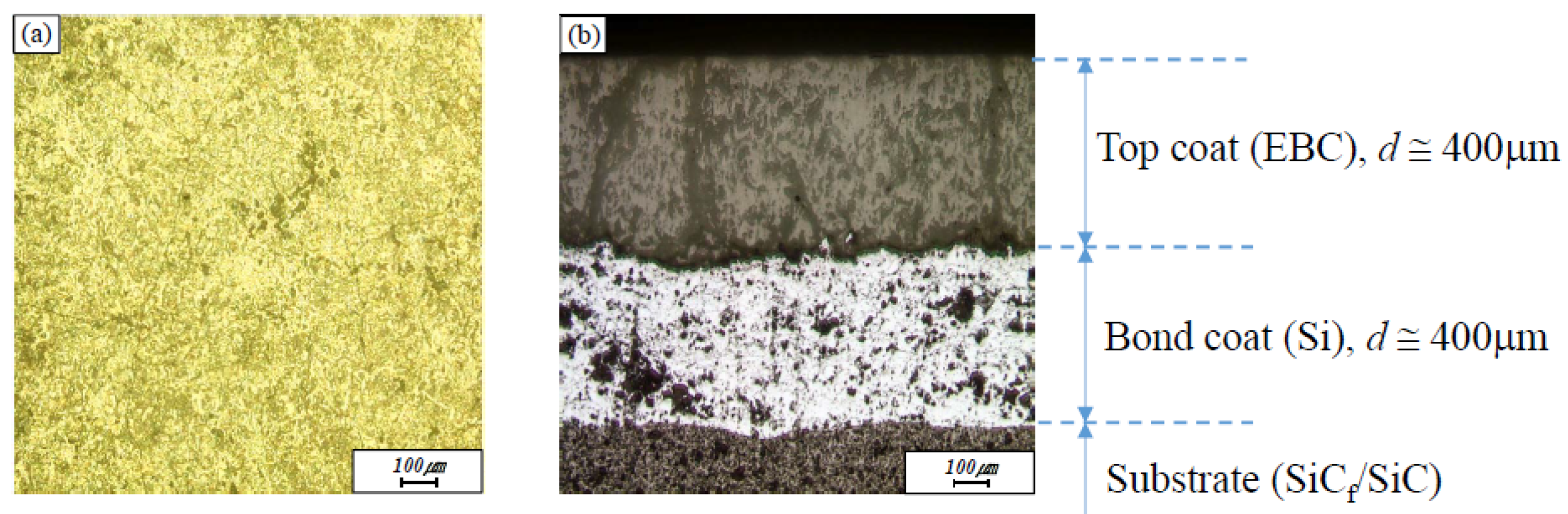
The surface of the coating layer was ground and then polished with 15, 6, 3 and 1 μm diamond suspensions to observe the cracks in the EBCs. The thickness was measured at each polishing step so that the degree of polishing was controlled to be the same for all samples.
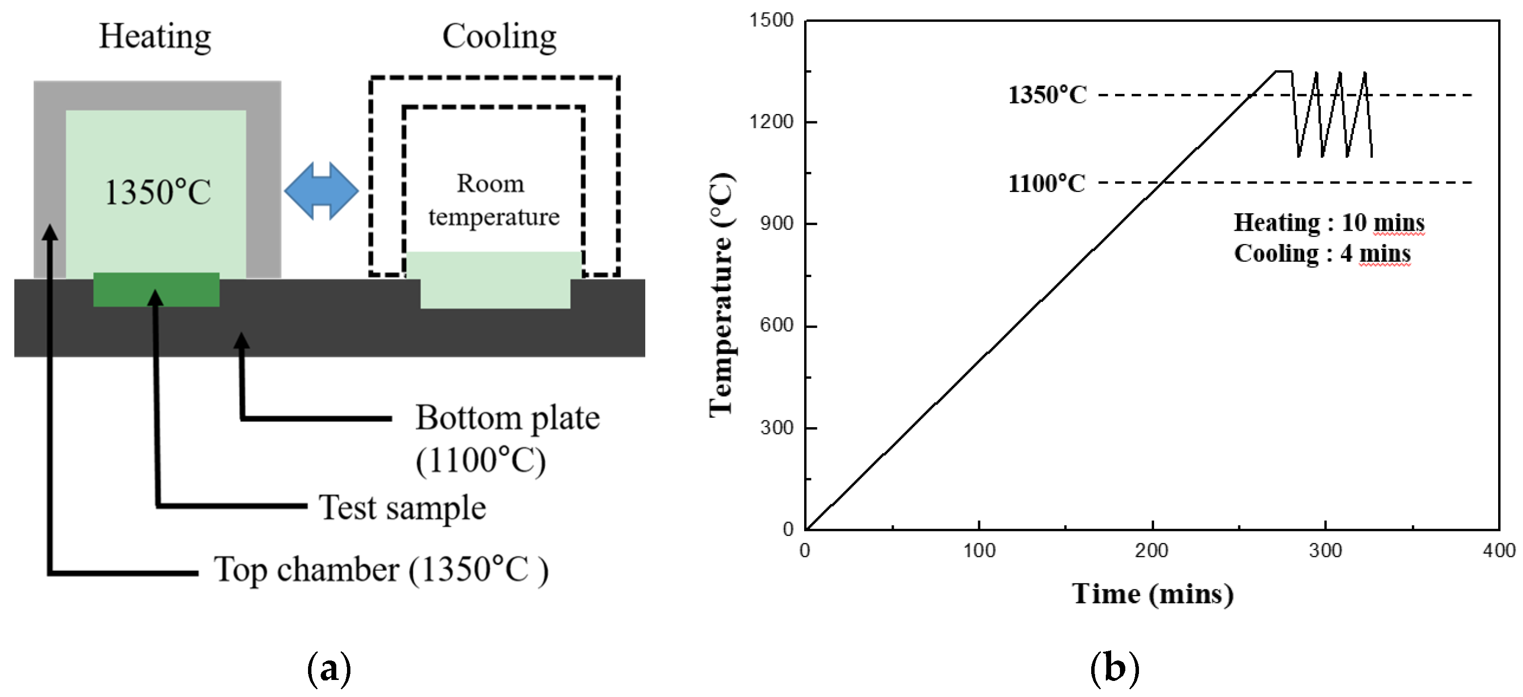
Thermal shock tests were performed to evaluate the durability of the EBC against repetitive thermal fatigue. The thermal shock was induced using a laboratory-made horizontal thermal shock machine in which the chamber could be moved horizontally by a motor. The schematic diagram of the thermal shock test is shown in
Figure 1a. The test samples were placed on a fixed hotplate such that the substrate was positioned to receive heat from the lower part of the hot plate, and the coating layer was exposed to the top to receive heat from the chamber. First, the test samples placed on the hotplate were maintained at a temperature of 1100 and 1350 °C in the upper coating layer after the heating chamber was closed; the heating rate was 5 °C/min. After the target temperature had been maintained for 10 min, the upper chamber was moved to expose the sample to room temperature for 4 min as shown in
Figure 1b, and then the chamber was moved back to expose the sample at 1350 °C again. This cycle was defined as one cycle, and repetitive thermal shocks were applied for a maximum of 5000 cycles.
We observed the surface using an optical microscope (Olympus, GX51, Tokyo, Japan) after thermal shock tests of 1000, 2000, 3000, 4000, and 5000 cycles. Cracks and damages were observed with an optical microscope, and the density of cracks was measured with an image analyzer. For this purpose, the surface was observed at 200× magnification using an optical microscope. The crack density was defined by measuring the number of cracks intercepting the baseline after the baseline had been marked at positions of 1/4, 1/2, and 3/4 of each line of the horizontal, vertical, and diagonal length, respectively. We defined the crack density as the number of cracks divided by the length of the baseline and expressed it in terms of the number per inch. The numbers of cracks were determined from 10 pictures, and the mean values were plotted. The crack morphology of the surface was also observed with a high-resolution optical microscope (VHX-5000, Keyence Co., Itasca, IL, USA) after thermal shock tests of 100 and 5000 cycles.
Scanning electron microscopy (SEM) was used to observe the cracks in detail after crack healing. The electron microscope (JSM-6010F, JEOL Co., Tokyo, Japan) was operated at an acceleration voltage of 10 kV. Energy-dispersive X-ray spectroscopy (EDS) was used to determine the element species with an acceleration voltage of 10 kV and a spot size of 3.0.
The phase of the coating layer was analyzed by X-ray diffraction (XRD, Rigaku Co., Ltd., Tokyo, Japan) to analyze the change in the phase before and after the crack healing. The XRD analyses were conducted with Cu Kα radiation generated at 45 kV and 200 mA with a scan rate of 2°/min over the 2θ range from 20° to 80°.
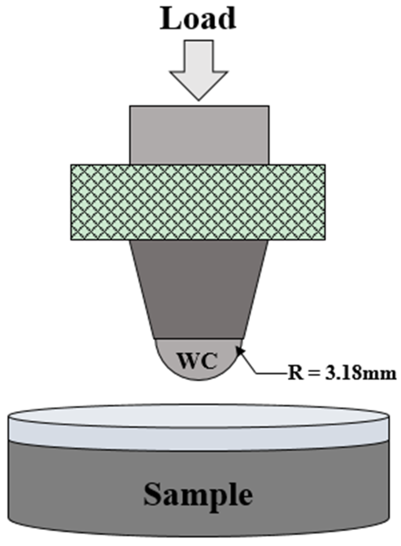
Spherical indentations were induced to compare and evaluate the mechanical behavior before and after the thermal shock test. The schematic diagram of spherical indentation is shown in
Figure 2. Indentation load–displacement curves were obtained during indentation tests. A tungsten carbide ball with a radius of
r = 3.18 mm was attached to the jig of a universal testing system (Instron 5567, Boston, MA, USA) and the pre-load was applied to the coating layer to
P = 10 N at a rate of 3 N/min. The load was then applied to
P = 500 N at a rate of 0.1 mm/min. The load was removed at the same rate as soon as the load had reached
P = 500 N. The displacement was measured with an extensometer during load changes. Tests were conducted on more than five areas of the coating layer of the test specimens, and the indentation load and displacement results were averaged and plotted. The relative hardness was calculated from relative displacement after unloading in each indentation load–displacement and compared [
23,
24,
25,
26].
3. Results and Discussion
The cracks formed on the surface and cross section of the EBC coating layer by thermal shock were observed by optical microscopy, as shown in
Figure 3. Thermal shock tests were carried out at 1350 °C on the coating surface of the sample and at 1100 °C on the bottom of the sample because a gas turbine operating at 1600 °C is cooled simultaneously by the cooling gas through the flow path. Mud-type cracks formed on the surface. After 100 thermal shock cycles, cracks developed in the EBC layer fabricated by APS, as shown in
Figure 3a. We considered that these cracks developed because of the difference in thermal expansion coefficients between the EBC coating and the metal sublayer. Several researchers have observed and reported mud cracks in EBCs [
8]. However, cross-sectional observations of these cracks reveal that they formed in a direction perpendicular to the interface, not parallel to the interface. The vertical cracks shown in
Figure 3b propagated through 400 μm of thickness; their propagation stopped at the top of the bondcoat layer. Such cracks can be stable if they do not induce horizontal cracking along the interface between the EBC and the sublayer, but rather tolerate strain caused by stress, thereby contributing to preventing delamination of the coating layer [
27,
28].
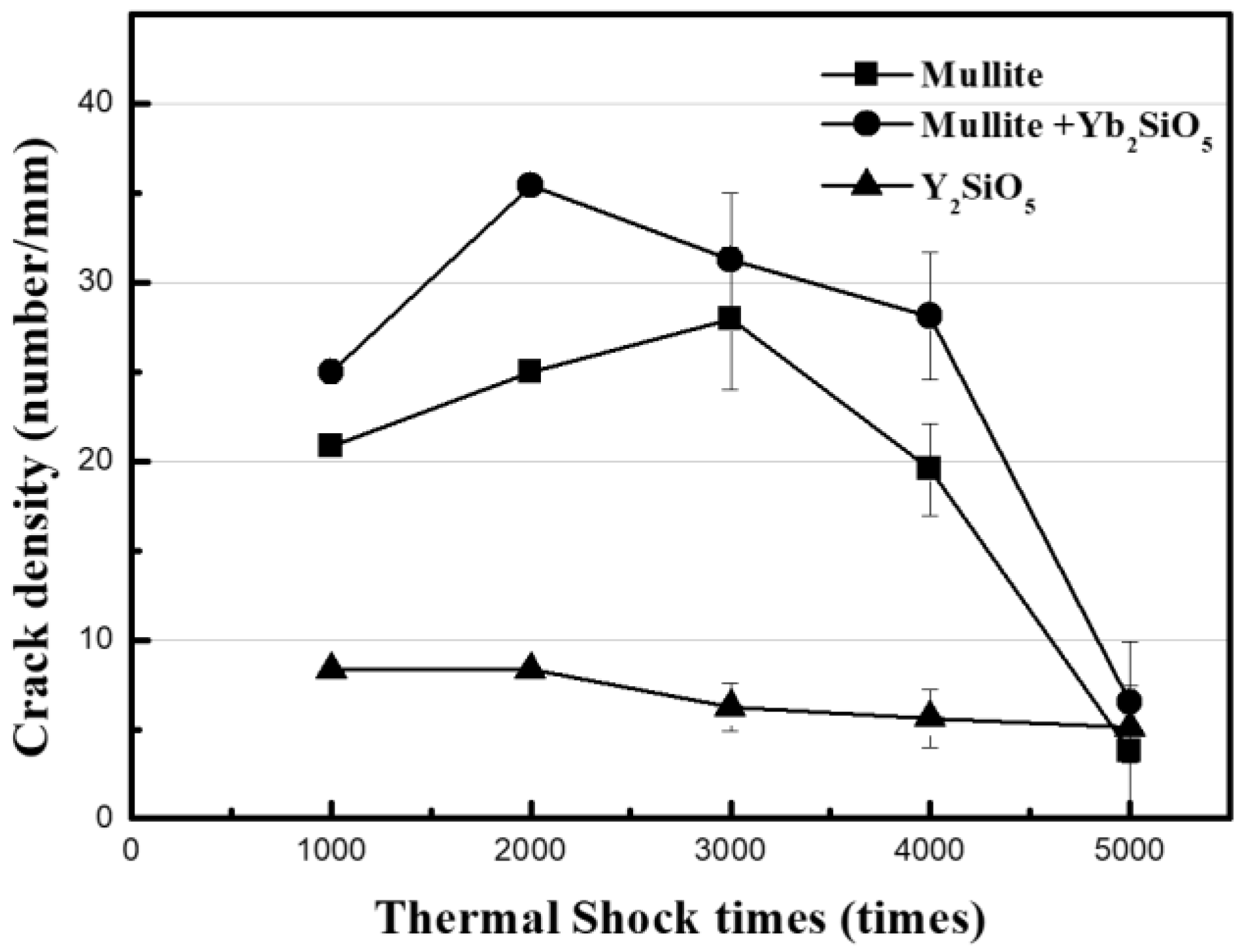
The results of the measurements of the crack density developed on the surface of the EBC by thermal shock are shown in
Figure 4. The periodic repetition of heating and cooling in turbine systems, and especially an abrupt stop of the system, will exacerbate crack formation. Therefore, the stability of cracks was evaluated by thermal shock tests. The mullite-based EBCs (i.e., the mullite and mullite + Yb
2SiO
5 EBCs) were not delaminated when the thermal shock cycle of exposure to room temperature was repeated for 5000 cycles while the coating material was maintained at 1350 °C and the SiC
f/SiC substrate material was maintained at 1100 °C. Even though a crack is generated initially, interface delamination does not occur because vertical cracks are formed. That is, an initially developed crack in the EBC layer is very stable. Although the Y
2SiO
5 EBC was stable for 4000 cycles, interface delamination occurred after 5000 thermal shock cycles. The crack density on the surface of a sample after each 1000 cycles in the thermal shock test was measured and plotted in
Figure 4. As shown in the graph, the changes in crack density depend on the EBC material. The crack density did not substantially change compared with the initial crack density in the case of Y
2SiO
5, whereas the crack density of the mullite-based EBC increased slightly and then drastically decreased after 3000 cycles. Furthermore, it exhibited a substantial decrease in crack density after 5000 cycles.
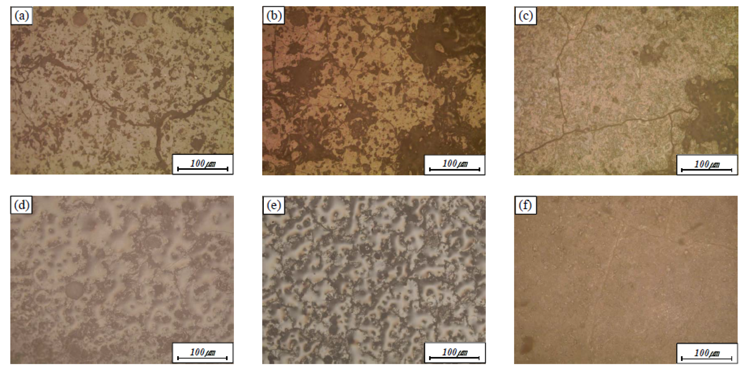
The optical microscope images in
Figure 5 show the surfaces of the mullite, mullite + Yb
2SiO
5, and Y
2SiO
5 after 2000 and 4000 cycles of thermal shock, indicating crack healing. Although obvious cracks are observed after 2000 cycles of thermal shock irrespective of the EBC material (
Figure 5a–c), surprisingly, the surface cracks were not observed after 4000 cycles of thermal shock (
Figure 5d–f). In the case of Y
2SiO
5, relatively large macrocracks developed and were maintained without the formation of microcracks; thus, the crack density did not substantially change. By contrast, the population of microscale cracks increased at 2000 cycles and new phases covered the surface completely at 4000 cycles in the mullite-based EBC.
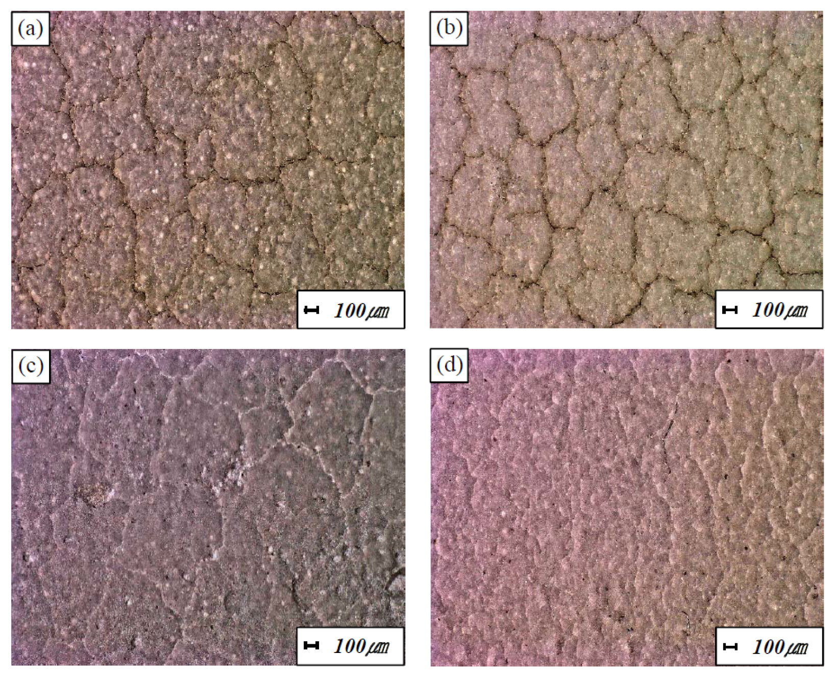
The cracks on the surface of the mullite-based EBC after 5000 cycles of thermal shock were observed with a high-resolution optical microscope, as shown in
Figure 6. The optical microscope images of the surfaces of the mullite-based EBC after 100 cycles are also presented in the figure. Although mud cracks were noticeable after 100 cycles of thermal shock, the crack gaps were clearly filled after 5000 cycles of thermal shock.
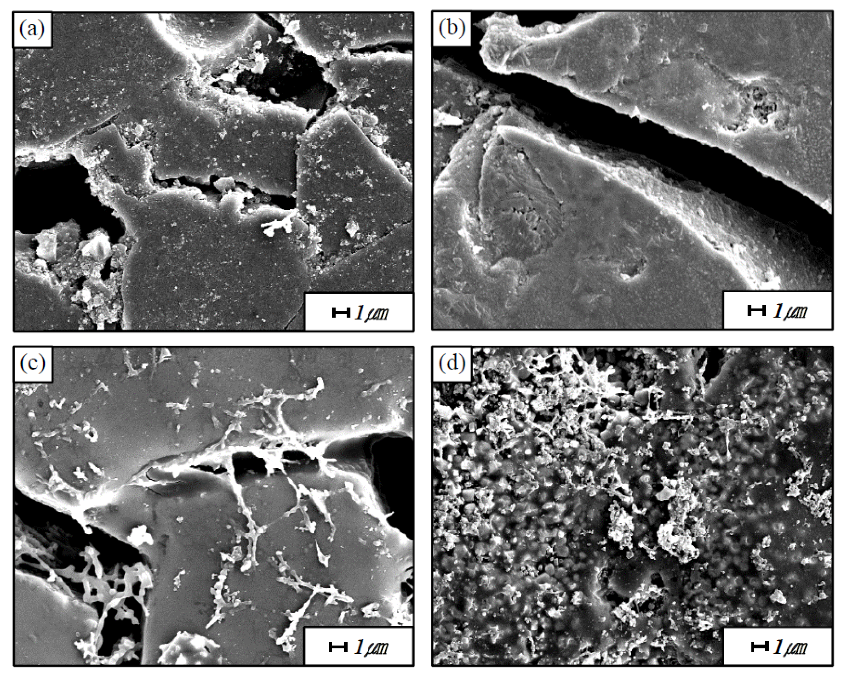
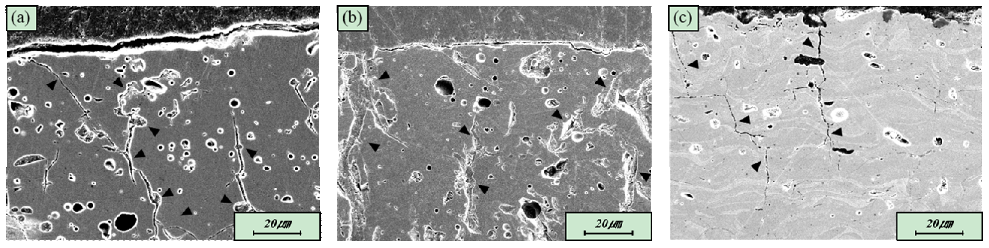
Figure 7 shows the cracks of the mullite-based EBC after 100 and 5000 thermal shock cycles, as observed at high magnification by SEM. Only cracks and grains are observed after 100 cycles of thermal shock; cracks are observed around the grain. By contrast, after 5000 thermal shock cycles, new phases are formed to fill the gaps and cover the cracks. The results of the EDS composition analysis of these phases indicate that they contain only Si and Al, which are the constituents of mullite. We therefore speculate that the mullite itself underwent a change when repeatedly exposed to high temperatures.
Figure 8 shows the cracks on the cross-section of the mullite, mullite + Yb
2SiO
5, and Y
2SiO
5 after 5000 thermal shock cycles, as observed by SEM. Each arrow in the mullite, mullite + Yb
2SiO
5 indicate crack healed region. On the other hand, each arrow in the Y
2SiO
5 indicate cracked region. Only cracks are observed after 5000 cycles of thermal shock in the case of Y
2SiO
5 (
Figure 8c). By contrast, after 5000 thermal shock cycles, new phases are formed to fill the gaps and cover the cracks, and this result is more pronounced in the mullite + Yb
2SiO
5 (
Figure 8b)
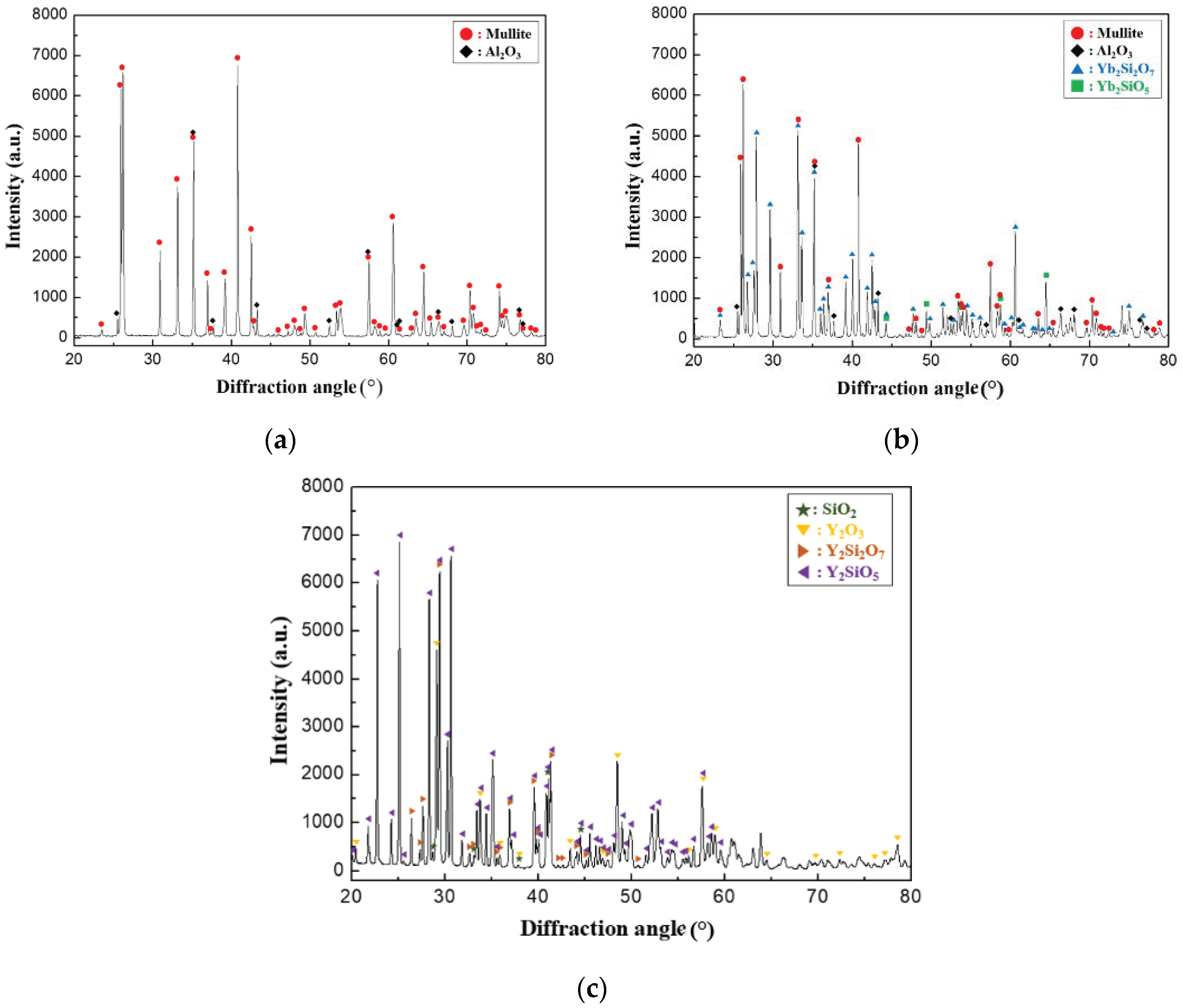
. XRD analysis was performed on the EBC materials after 5000 thermal shock cycles for the analysis of the phases formed around the cracks, as shown in
Figure 9. In the case of the mullite material, an Al
2O
3 phase was detected in addition to the mullite phase. Therefore, the newly formed phases in
Figure 7 and
Figure 8 are attributed to mullite that melted under repeated thermal shock cycles at high temperature. We speculate that the low-melting-point phases containing SiO
2 migrated into the cracks, filling the gaps of the cracks, and that the Al
2O
3 phases precipitated as crystalline phase during cooling. In particular, Al
2O
3 phases are considered desirable because they exhibit excellent oxidation and corrosion resistance at high temperatures and can therefore resist oxidation and corrosion of EBC materials after crack healing. Similarly, an Al
2O
3 phase was detected along with the mullite, Yb
2SiO
5, and Yb
2Si
2O
7 phases in the case of the mullite + Yb
2SiO
5 material, as shown in
Figure 9b. However, in the case of Y
2SiO
5, Y
2O
3, and SiO
2 phases were detected along with Y
2SiO
5 and Y
2Si
2O
7 phases, as shown in
Figure 9c. The Y
2SiO
5 phase melts at high temperatures and is decomposed into crystalline Y
2O
3 and SiO
2, similar to the process that occurs in the mullite-based EBC.
Rare-earth silicate materials such as Y
2SiO
5 and Yb
2SiO
5 have been reported to exhibit less mass loss than mullite in a steam atmosphere at relatively higher temperatures [
11,
17,
29,
30]. However, if cracks occur in the coating layer because of thermal shock, the crack healing ability of Y
2SiO
5 and Yb
2SiO
5 is considered to be relatively poor. Therefore, studies are needed to develop a eutectic phase or new crack healing agent. The mullite + Yb
2SiO
5 material suggested in this study exhibits high water vapor resistance because of the Yb
2SiO
5 phase and exhibits crack healing behavior because of the mullite phase. Therefore, the mullite + Yb
2SiO
5 can be used as a high-temperature EBC material with crack healing ability.
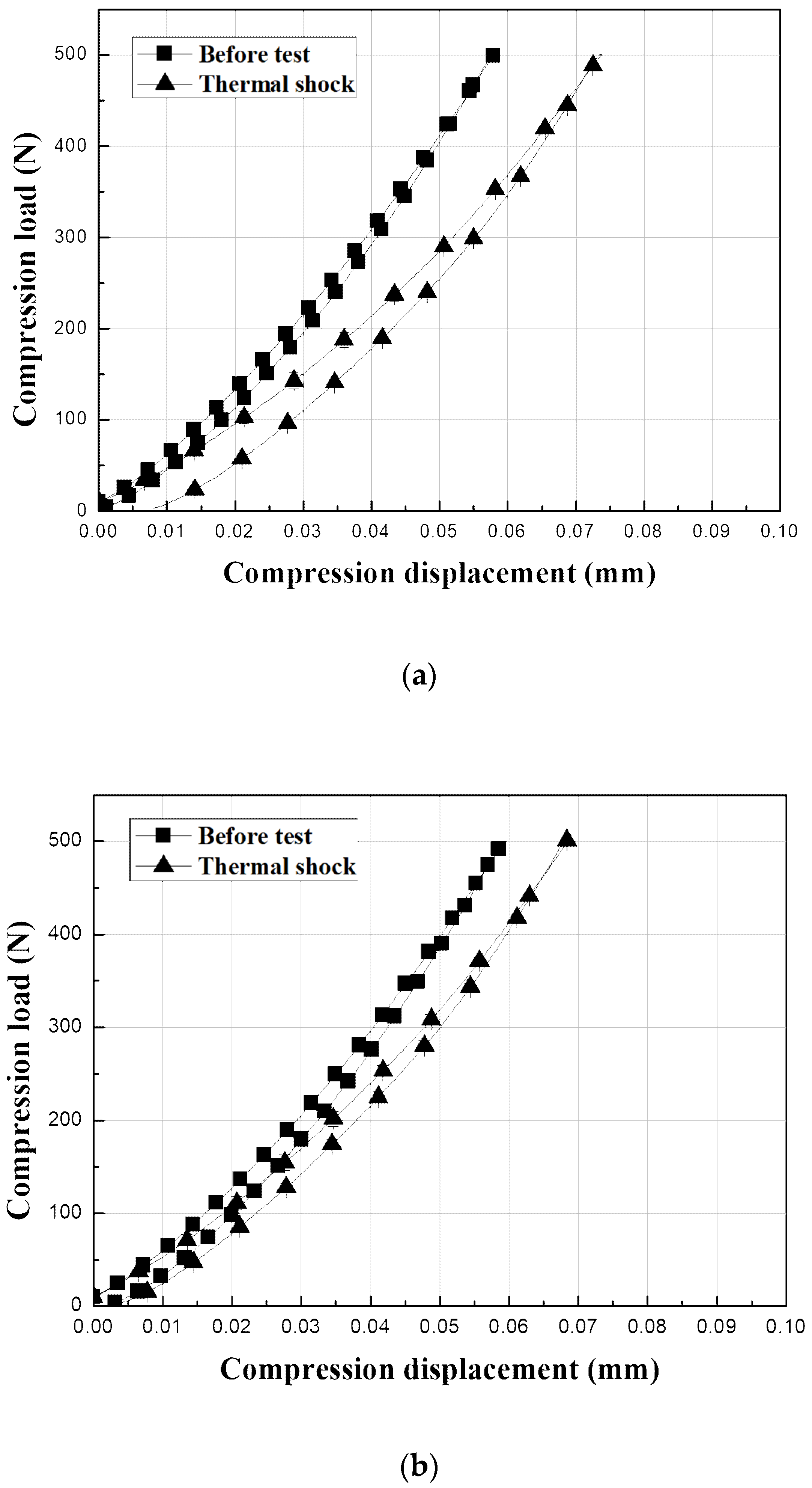
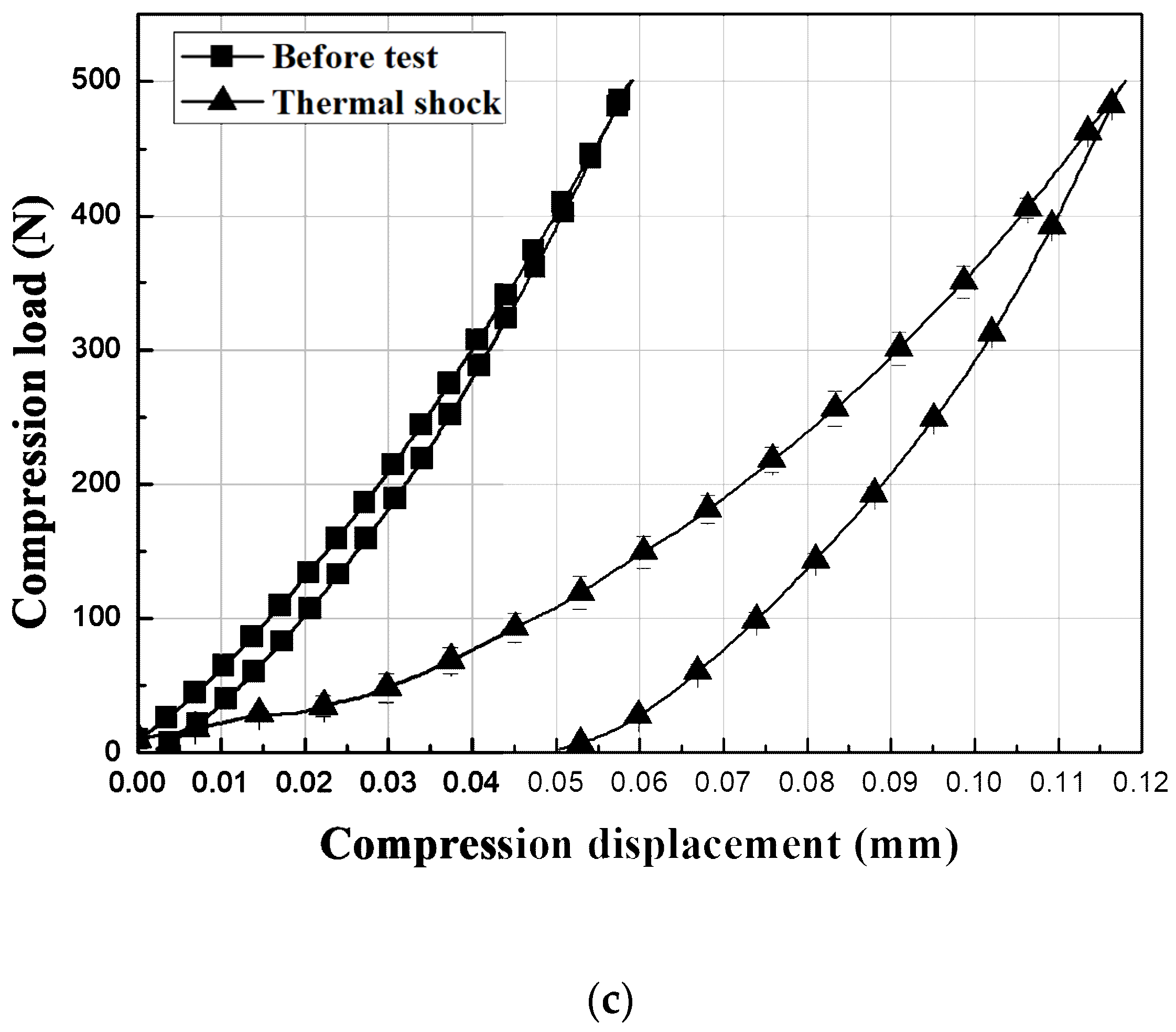
The surfaces of the EBC materials were contacted with a WC ball with a radius of 3.18 mm to a load
P of 500 N and then unloaded to determine the mechanical behavior after crack healing, as shown in
Figure 10. The graphs show the test results for the sample before the thermal shock and the sample after 5000 thermal shock cycles. The Y
2SiO
5 EBC shows a large change from elastic to plastic after 5000 thermal shock cycles, as shown in
Figure 10c because the test was carried out on the delaminated coating samples. By contrast, the load–displacement behavior of the mullite-based EBCs, which did not exhibit interfacial delamination even after 5000 thermal shock cycles, did not substantially differ from their initial indentation load–displacement behavior, as shown in
Figure 10a,b. In the case of mullite, the residual displacement related to the hardness of the material was slightly increased after thermal shock, and the tangential slope of the stress–strain at unloading, which is related to the modulus of elasticity, decreased after thermal shock [
10,
25,
26,
31]. Thus, the hardness and elastic modulus of the sample decreased by 5000 thermal shock cycles. The decrease in the mechanical properties is attributed to cracks even though the sintering of the material during repetitive exposure to high temperatures occurs [
32,
33]. However, the hardness and elastic modulus of the mullite + Yb
2SiO
5 did not substantially change even after 5000 thermal shock cycles. Therefore, the initial mechanical properties of the mullite + Yb
2SiO
5 were recovered by crack healing.
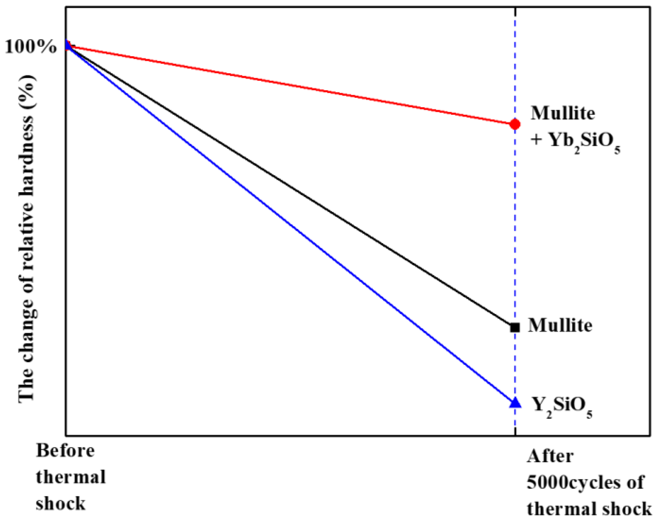
Figure 11 shows the change in the relative hardness of the material, as revealed by analysis of the residual displacement of the indentation load–displacement curves in
Figure 10. The hardness value before the thermal shock test is assumed to be 100%, and the hardness value after 5000 cycles of thermal shock is plotted in percent. As shown in the graph, the mullite + Yb
2SiO
5 maintains its initial hardness value. These results indicate that the mullite + Yb
2SiO
5 is a potential EBC material because gas turbine coating materials exposed to repeated thermal cycles must not only not exhibit interfacial delamination due to the thermal shock but also resist impact and wear due to external FOD.
