Abstract
In the digitalization of production, temperature determination is playing an increasingly important role. Thermal spraying and magnetron sputtering were combined for the development of Ni/Ni-20Cr thin film thermocouples for plastic flat film extrusion processes. On the thermally sprayed insulation layer, AlN and BCN thin films were deposited and analyzed regarding their structural properties and the interaction between the plastic melt and the surfaces using Ball-on-Disc experiments and High-Pressure Capillary Rheometer. A modular tool, containing the deposited Ni/Ni-20Cr thin film thermocouple, was developed and analyzed in a real flat film extrusion process. When calibrating the thin film thermocouple, an accurate temperature determination of the flowing melt was achieved. Industrial type K sensors were used as reference. In addition, PP foils were produced without affecting the surface quality by using thin film thermocouples.
1. Introduction
Self-learning machines play a crucial role in today’s and future production. In the 4th Generation Industrial Revolution (Industry 4.0), machines are digitally upgraded and merged to a big data environment [1]. The overall goal is the improvement of product quality and production scheduling by building up and using prediction tools [1]. However, self-learning machines are still far from being implemented in many industries [1]. Data required for these prediction tools can only be generated if the machines are equipped with corresponding sensors, such as temperature-, wear-, distance-, or pressure-sensors, that work exactly. In many areas, the determination of the temperature, in particular, plays an important role. For this purpose, especially thin film thermocouples are suitable, since they reveal a lower mass and thus a faster reaction time in contrast to bulk thermocouples [2]. Multi-functional PVD coatings are successfully used for the temperature measurement in combustion engines [3] or gas turbine engines [4], for example. However, there is also a need for thin film thermocouples in production processes. Therefore, different thin film thermocouples are currently developed for several applications, such as welding [5] or metal [6,7,8,9] and polymer processing [10,11]. However, the thin film thermocouples must be adapted to the respective application fields. On the one hand, the materials of the thermocouples need to be selected according to the desired temperature range. According to DIN EN 60584, eight different thermocouple pairs are available, whereas Fe–CuNi [12], Cu–CuNi [13], NiCr–Ni [6,7,8,9] and Pt-10%Rh/Pt [14] are the most reported thin film thermocouples deposited by means of PVD. Apart from the standardized thermocouples, TiC–TaC [15], Al–Au [11], Ni–Cu [12,16], Ni–Fe [12], Cu–Fe [12], Chromel–Alumel [5,12], and Pt–Pd [4] thin film thermocouples are synthesized. On the other hand, depending on the application, the thin film thermocouples need to be protected against wear or oxidation processes by means of a suitable tribological cover layer. To enhance the wear resistance of thin film sensors, protection layers consisting of Al2O3 [7,14,16,17], AlN [17], or TiN [8,18] are mainly used. For electrical isolation purposes, HfO2 [6] and Al2O3 [16] layers are utilized.
In plastic processing, thermoplastics are extruded into semi-finished products that can be processed further (e.g., films). The plastic is plasticized and formed in the die [19]. For a good product quality, the melt needs to flow through the die at constant pressure, throughput and temperature [20]. In particular, an accurate measurement of the melt temperature is preferred and helps to increase the productivity. Temperature sensors are part of every extruder system, so that the time stability and the absolute level of the melt temperature can be monitored. Malfunctions can be detected quickly and the reaction time to undesired temperature changes increases. Nevertheless, state-of-the-art touching sensors cannot be used in the die itself because of the negative impact of the sensors on the product quality. The measurement tip protrudes at different depths into the melt and can disturb the homogeneity in the process itself. Thin film thermocouples offer an alternative measuring method to conventional sensors due to their flat construction and low net weight. In addition, they offer the possibility to measure the temperature even when embedded in the wall. Especially, in the case of embedded sensors, it is important to measure the temperature of the melt and not of the die wall. Therefore, thin film thermocouples are to be thermally insulated from the die walls. Thermal sprayed barrier coatings, such as ZrO2 and Al2O3, are particularly suitable for thermal insulation applications since they reveal pores and a higher thickness compared to sputtered coatings. Therefore, these coatings were applied by means of atmospheric plasma spraying and serve as substrate for the thin film thermocouples [19,20]. In particular, in film extrusion, it is important that the melt flow is not impaired to ensure a homogeneous film quality. Accordingly, the influence of different PVD top coatings on the wall friction and the adhesion of the melt is investigated. Since AlN coatings reveal high electrical resistance and high thermal conductivity, three AlN thin films deposited with different sputter parameters are selected. As an alternative, BCN is used as additional top coat. Finally, the application of the Ni/Ni-20Cr thin film thermocouple is proved in a real operation test und compared to a reference bulk thermocouple.
2. Materials and Methods
2.1. Deposition Process
For the deposition of the nitride thin films and the Ni/NiCr thin film thermocouples, the industrial scale magnetron coating system CC800/9Custom (CemeCon AG, Würselen, Germany) was utilized. The AlN and BCN thin films were synthesized on AISI 1045 steel substrates (Ø40 mm), which were prior coated with Al2O3 using atmospheric plasma spraying. Detailed spray parameters of the Al2O3 coating are reported in [21]. The nitride thin films were deposited in medium frequency (MF) mode using one B4C (99.50% purity, Sindlhauser Materials GmbH, Kempten, Germany) and two Al (99.50% purity, CemeCon AG, Würselen, Germany) targets operating with 3150 W and 2× 1875 W at a total chamber pressure of 330 mPa. The frequency was set to 50 kHz with a duty cycle of 50%. Three AlN thin films and one BCN thin film were synthesized using different heating powers and Ar/N2 gas flow rates according to Table 1. The heating power was changed to influence the crystallinity and the topography of the AlN thin films. Changing the Ar/N2 gas flow ratio results in a change of the chemical composition of the coating. Therefore, it was possible to analyze which properties influence the melt flow, respectively, the friction behavior. The two-fold rotation system was biased with –150 V in MF mode during all deposition processes. The deposition time of all coatings was adjusted to achieve comparable thin film thicknesses of approximately 1200 nm. The thickness was measured analyzing the cross section of the coatings by means of scanning electron microscopy.

Table 1.
Deposition parameters of the AlN and BCN thin films.
In addition to the reference nitride layers, Ni/Ni-Cr thin film thermocouples were synthesized for the temperature measurement of the plastic melt in flat film extrusion processes. Therefore, a modular tool system was developed. This system consisted of a screw-in bush (AISI 4140), a ceramic insert, and a locking nut. The bush can be integrated into the die by means of a drilling with a thread (M24 × 1.5). The ceramic insert was coated with the thin film thermocouples. By means of a step on the one side and a locking nut on the other side, the thin film thermocouple was positioned and fixed in the bush. The ceramic insert was composed of a steel core (AISI 1045), which was coated by atmospheric plasma spraying from all sides. For a sensitive temperature measurement, the insert had to be thermally insulated from the die walls, since the temperature of the on-rushing plastic melt was measured. The thermal insulation was achieved by a thermal sprayed multilayer design consisting of a 120-µm-thick NiCoCrAlTaY (AMDRY 997, Sulzer Metco, Pfäffikon, Switzerland) bond coat, a 530-µm-thick 7Y2O3-ZrO2 (AMPERIT 817.7, HC Starck, München, Germany), and a 680-µm-thick Al2O3 (Metco 6062, Sulzer Metco, Pfäffikon, Switzerland) ceramic coating. After the coating processes, the Al2O3 coating was entirely ground to a thickness of 350 µm, resulting in a total coating thickness of 1000 µm. After the grinding process, the outsides were polished in several steps to a roughness of Ra = 0.212 ± 0.104 µm.
The step of the ceramic insert was manufactured using a micro milling machine HSPC 2522 (Kern, Eschenlohe, Germany) equipped with a solid carbide end mill, type 910 Marlin, with a corner diameter of 1 mm (Zecha, Königsbach-Stein, Germany). The milled surfaces reveal a roughness of Ra = 0.811 ± 0.116 µm.
After processing the final dimensions of the ceramic inserts, they were cleaned of contaminations by means of ethanol in an ultrasound bath. Thereafter, the Ni/Ni-Cr thin film thermocouple was deposited on the ceramic inserts using a steel masking system reported in [22] to synthesize the individual Ni and Ni-20Cr conducting paths. The conducting paths were sputtered in DC mode using a heating power of 1200 W and a Ar/Kr gas flow rate of 2.7 at a chamber pressure of 250 mPa. For the Ni conducting path, two Ni targets (99.99% purity, Sindlhauser Materials GmbH, Germany) were operated at 1875 W in DC mode, whereas for the Ni-20Cr path, a Cr target (99.95% purity, Sindlhauser Materials GmbH, Kempten, Germany) was operated at 1035 W, additionally. The deposition time of both conducting paths was adjusted to reveal similar thicknesses of 1050 ± 35 nm.
2.2. Characterization
The structural properties of the as-deposited nitride thin films were analyzed by means of X-Ray Diffraction (XRD) utilizing the diffractometer D8 Advance (Bruker, Madison, WI, USA). The thin films were investigated using Cr-radiation (2.29106 Å), whereas the current and voltage were set to 40 mA and 35 kV. To avoid an overlapping of the reflexes from the Al2O3 substrate, detector scans were performed, whereby the tube was set to an incident angle of 5°. The topography and morphology of the AlN and BCN thin films were investigated using the Scanning Electron Microscope (SEM) JSM 7001F (Jeol, Tokyo, Japan). The roughness Ra of the Al2O3 substrate, as well as the thin films, was measured by the confocal white-light microscope µSurf (NanoFocus, Germany). The mechanical properties hardness (H) and Young’s modulus (E) were examined by means of a nanoindentation test using the nanoindenter G200 (Agilent Technology, Santa Clara, CA, USA). The evaluation was performed in a depth between 100 and 400 nm using the equations in accordance to Oliver and Pharr [23]. Thereby, a constant Poisson’s ratio of 0.25 was assumed. The adhesion of the nitride thin films under plastic deformation was tested by a Rockwell indentation test in accordance with DIN EN ISO 26443 [24], using a force of 60 kgf and a dwell time of 4 s. Tribological investigations were carried out using a high-temperature Ball-on-Disc tribometer (CSM-Instruments, Peseux, Switzerland). The velocity was set to 0.1 m/s, the normal force to 10 N, and the radius to 8 mm with a total distance of 20 m per experiment. Counter body balls (Ø6 mm) made of Polypropylene (PP) were used, since this material was used for the operation test of the thin film thermocouples. The tribological investigations were carried out at 85 °C (Vicat Softening Temperature) and 153 °C (Heat Deflection Temperature) to simulate a non-steady-state operating point of the plastic flat film extrusion process during heating up or cooling down. The adhesion of the PP to the coating surface was investigated by means of SEM. Additionally, the wear of the PP balls was analyzed using a confocal light microscope type InfiniteFocus (Alicona, Raaba/Graz, Austria). By utilizing a High-Pressure Capillary Rheometer (HPCR), the influence of the different coatings on the melt flow was investigated. The measurement was carried out according to DIN 54811. When measuring with the HPCR, first, a purely thermal melting takes place in a pre-chamber. In order to melt the material completely, the definition of a residence time is important. For the investigations with the Moplen HP420 M, a duration of 4 min was specified. After melting, a piston pushed the melt through the tempered capillary. The capillary was preheated to a certain temperature by two thermal sensors. The operating temperature for the measurements was set to 230 and 250 °C. The capillary was preheated to the desired temperature by means of two sensors. The piston speed and the pressure loss of the melt flow were recorded simultaneously by means of a pressure sensor.
For the operational test, a wide-slot die was used, which allows to measure the melt temperature. The positioning of the thermocouples was important for the accuracy and reproducibility of measuring points. The thin film and industrial thermocouples were inserted near to the melt outlet from the die. The investigations were carried out using an extruder with a diameter of 45 mm and a typical three-zone screw for plasticizing (Battenfeld-Cincinnati Gmbh, Germany). The mass temperature measurements were carried out using a high density Polyethylen, while for the film production, a high flow polypropylene homopolymer (Moplen HP420M, lyondellbasell, Rotterdam, The Netherlands) was selected. Furthermore, for producing films, a chill roll unit was used (Collin GmbH, Maitenbeth, Germany). To compare the thin film sensors with conventional sensors of type K (Gneuss GmbH, Bad Oeynhausen, Germany), sensors with measuring tips (depth length) of 0, 0.5, and 1.5 mm were also utilized to measure the melt temperature and serve as reference. Besides the operational tests, the quality of the produced film was examined for evaluating the influence of the measuring tip of the industrial sensors. The optical properties of the film were determined by measuring the reflection and the transmission. An optical spectroscope HR2000+ (Ocean optics, EW Duiven, The Netherlands) enabled the measurement of the film quality. The measuring setup was in accordance with DIN 5036-3. Optical spectroscopy enabled a fast quality criterion for the evaluation of samples. In this method, a light beam with an intensity I0 irradiated the sample, while the exit intensity was recorded. The radiation sources covered a selected wavelength range, respectively, a certain spectrum. The intensity of the light depends on the wavelength λ and, accordingly, a function I(λ) of the light intensity [25]. The spectrum of the incident intensity was compared over the wavelength with the spectrum of the incident intensity. In the present study, the visual spectrum (VIS), which reveals wavelengths of approximately 380–780 nm, was used. When the light beam hits the matter, the light is distributed to different parts and the following output intensities are generated: The reflected IR, the transmitted IT, the scattered IS, and the absorbed intensity IA. These intensities form in sum I0 [25].
3. Results
3.1. AlN/BCN Thin Films
3.1.1. Structure and Morphology
XRD patterns of the three AlN and the one BCN coatings synthesized with different deposition parameters are presented in Figure 1. For the AlN thin films, the positions of the reflections are 2θ ≈ 50.2°, 2θ ≈ 54.7°, 2θ ≈ 57.7°, 2θ ≈ 77.4°, 2θ ≈ 94.8°, and 2θ ≈ 106.6°, which correspond to the hexagonal AlN phase (JCPDS 25-1133). The reflections of the three AlN thin films reveal comparable intensities, showing a similar crystallinity. Nevertheless, slight differences can be detected. The AlN-3 thin film shows the highest crystallinity, which is favored by the higher nitrogen flow during the coating process. At constant gas flow, the AlN-2 film shows a slightly higher crystallinity compared to the AlN-1 film, which is due to the higher deposition temperature. Compared to the AlN-3 thin film, the AlN-1 und AlN-2 thin films reveal small additional peaks at 2θ ≈ 69.0° and 2θ ≈ 106.4°, which correspond to the cubic AlN phase (JCPDS 46-1200). However, none of the AlN thin films show a high crystallinity, which is also shown by the broad peaks. Some of these also overlap with the comparable structure of the substrate, which makes accurate evaluation difficult. The wurtzite-type AlN was already obtained by Aissa et al. for a dc and high power impulse magnetron sputtering process [26]. The remaining reflections, marked with a black circle, belong to the cubic (α) and trigonal (γ) Al2O3 phase of the thermally sprayed substrate. Concerning the BCN coating, basically, only peaks of the substrate are visible, which indicates a nearly amorphous state of the thin film. Only slight reflections at 2θ ≈ 52.8° and 2θ ≈ 57.4° are observed, which coincide with the position of rhombohedral B4C.
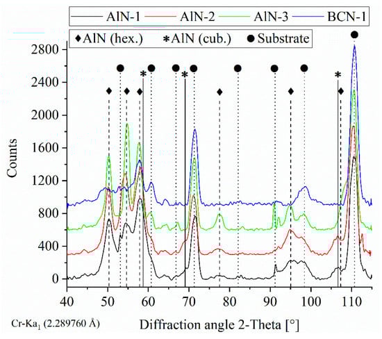
Figure 1.
XRD patterns of the AlN-1, AlN-2, AlN-3, and BCN thin films deposited with various parameters.
Additionally, the nitride thin films were analyzed regarding topography and morphology by means of SEM, as shown in Figure 2. It can be seen that the thermally sprayed Al2O3 coating, which was used as substrate for the thin films, reveals a fine topography accompanied by a small crack pattern in the polished state. The AlN-1 and AlN-2 thin films possess a coarse cauliflower-like topography. By contrast, the AlN-3 thin film shows a fine structured topography. Accordingly, a high Ar/N2 gas flow ratio of 6.0 and high heating powers of 5000 and 7000 W, as is the case for the AlN-1 and AlN-2 coatings, lead to a coarse topography. The structure of the topography can be correlated with the XRD pattern shown in Figure 1. The AlN-1 and AlN-2 thin films reveal a lower crystallinity compared to the AlN-3 thin film and a small amount of a second phase, which results in the coarser growth behavior. The BCN-1 coating reveals an even finer structure, which is comparable to the polished Al2O3 surface. The cross-sections of all thin films show a glass-like featureless structure.
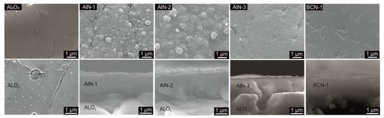
Figure 2.
SEM images of the topography (top) and morphology (bottom) of the AlN-1, AlN-2, AlN-3, and BCN thin films, as well as the thermally sprayed Al2O3 coating.
3.1.2. Mechanical Properties
Using nanoindentation, the mechanical properties—hardness and Young’s modulus—of the thin films, as well as the Al2O3 coating, were analyzed. As listed in Table 2, the Al2O3 coating reveals a hardness of 13.8 ± 3.9 GPa and a Young’s modulus of 155.2 ± 31.9 GPa. The AlN-1 and AlN-2 thin films reveal the lowest hardness of 6.0 ± 1.6 GPa and 6.2 ± 2.0 GPa, respectively. A higher hardness of 13.6 ± 3.0 GPa is analyzed for the AlN-3 thin films, which reveals a finer structure compared to the AlN-1 and AlN-2 thin films. The highest hardness of 19.1 ± 2.3 GPa is obtained for the BCN-1 coating. With increasing hardness, the Young’s modulus increases from 98.6 ± 21.2 GPa (AlN-1) to 187.7 ± 20.2 GPa (BCN-1). AlN thin films deposited on stainless steel substrates by means of magnetron sputtering reveal similar hardness values between 6 and 14 GPa in dependence on the bias-voltage as reported by Choudhary et al. [27]. The H/E ratio, which demonstrates the resistance to plastic deformation, is between 0.048 (AlN-2) and 0.102 (BCN-1). Since a higher value demonstrates a higher resistance to plastic deformation, the BCN-1 and AlN-3 thin films, as well as the uncoated Al2O3 coating, are the best choices as top layer for the application in plastic melt extrusion dies.
Table 2.
Roughness and mechanical properties of the nitride thin films, as well as the Al2O3 coating.
Hence, the thin films were exposed to high pressures in the nozzles without abrasive particles occurring. The adhesion of the thin films was analyzed by means of a Rockwell indentation test, which represents the thin film behavior under plastic deformation. The corresponding light microscope images of the indents are shown in Figure 3. According to DIN EN ISO 26443, the adhesion of the thin films can be classified into four different classes. Thereby, class 0 represents a coating without cracks and local delamination, and class 3, full delamination of the coating after indentation. The thin films AlN-2 and BCN-1 are classified as class 1, since they reveal only slight cracks around the indent. AlN-1 and AlN-3 correspond to class 2, showing local delamination. Accordingly, the adhesion strength of the thin films decreases with decreasing heating power, respectively, deposition temperature. The lowest adhesion is shown by the AlN-3 thin film, deposited at the lowest temperature and with the highest nitrogen gas flow.
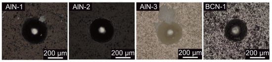
Figure 3.
Light microscope images of the Rockwell indents of the AlN-1, AlN-2, AlN-3, and BCN thin films.
3.1.3. Tribological Properties
Polymer processing mainly TiN, CrN, TiAlN, Cr1−xAlxN, CrAlON, and DLC coatings deposited by means of PVD were investigated and used [28,29,30]. It was shown that the addition of Al to CrN increases the contact angle between the surface and Polycarbonate melt, resulting in a lower adhesion. Therefore, the AlN and BCN thin films were investigated regarding their tribological properties. Tribological experiments were conducted at 85 and 153 °C using PP counter balls, whereby the temperatures are the Vicat Softening Temperature and the Heat Deflection Temperature. These temperatures were selected to simulate the adhesion behavior of the PP melt to the different top layer-coated thin film thermocouples during heating up or cooling down processes of the thin film extrusion process. Different friction coefficients between the melt and the thin film thermocouple, as well as the uncoated extrusion die, can lead to inhomogeneous film qualities due to different friction forces. Since the extrusion die was made of AISI H11 (1.2343) steel, this steel was used as reference for the tribological experiments. In Figure 4, the friction coefficients of the AlN-1, AlN-2, AlN-3, and BCN-1 thin films, as well as the steel substrate and the Al2O3 coating, are shown for temperatures of 85 and 153 °C using PP counter balls. It was observed that there is no temperature dependency of the friction coefficient, except for the reference steel and the Al2O3 coating. At 85 °C, a friction coefficient of 0.52 ± 0.11 is measured for the steel substrate, which drops down to 0.27 ± 0.05 at 153 °C. A contrary behavior is observed for the Al2O3 coating; the friction coefficient increases from 0.42 ± 0.10 at 85 °C to 0.66 ± 0.16 at 153 °C. Concerning the thin films, they basically reveal comparable friction coefficients independent from the used deposition parameters. The lowest friction coefficient of 0.28 ± 0.05 is obtained for the AlN-2 thin film, which slightly increases in the order AlN-1, AlN-3 up to 0.39 ± 0.07 for the BCN-1 thin film at 85 °C. In a different study, Ball-on-Disc experiments were also used to investigate the friction coefficient between CrAlN, respectively, DLC thin films and Polycarbonate counter balls [31]. It was shown that the friction coefficient depends on the temperature, and the adhesion behavior is related to the surface energies of the deposited thin films and surfaces. Moreover, it was reported that the friction coefficient depends on the roughness of the surfaces. Smoother surfaces lead to a higher fraction of the adhesive effect on the friction, which in turn leads to a higher coefficient of friction [32]. In fact, the obtained friction coefficients at 85 °C can be tendentially correlated with the roughness. The polished steel surface reveals the smoothest surface with a roughness of Ra = 0.006 ± 0.001 µm and the highest friction coefficient. The second lowest roughness is shown by the thermally sprayed Al2O3 coating, which shows the second highest roughness. Higher roughness and lower friction coefficients were analyzed for the thin films. At 153 °C, the influence of the roughness on the friction coefficient is not observed. The melting point of PP is between 160 and 165 °C, and therefore the mechanical properties of PP are already decreased at 153 °C. The surface of the Al2O3 coating contains defects such as pores, as shown in Figure 2, which affect the friction behavior, especially in contact with a soft material as also shown by the large deviation bar of the friction coefficient. Therefore, the Al2O3 coating reveals a higher friction coefficient at 153 °C compared to the other thin films.
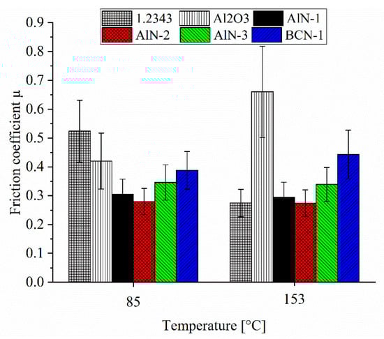
Figure 4.
Friction coefficient of the AlN-1, AlN-2, AlN-3, and BCN-1 thin films, as well as the steel substrate and the Al2O3 coating, at 85 and 153 °C using PP counter balls.
In addition to the frictional forces, a comparable adhesion of the plastic to the thin film thermocouple and the extrusion die is to be ensured. Therefore, the wear of the PP balls after the Ball-on-Disc experiments was analyzed, which is an indirect hint for the adhesion behavior to the used coatings. As visualized in Figure 5, the wear coefficients of the PP balls are between 16.9 ± 1.3 × 10⁻⁵ mm³/Nm (AlN-3) and 34.3 ± 5.1 × 10⁻⁵ mm³/Nm (AlN-1) for the PVD coated counter parts, whereas a wear coefficient of 26.7 ± 3.4 × 10⁻⁵ mm³/Nm is analyzed for the uncoated steel counterpart at 85 °C. Using the thermally sprayed Al2O3 coating as a counter body, a wear coefficient of 10.6 ± 0.6 × 10⁻⁵ mm³/Nm is noticed. Accordingly, at 85 °C, all counterparts cause a comparable wear coefficient of the PP balls, since the maximum difference of the wear coefficient is 23.7 × 10⁻⁵ mm³/Nm within the analyzed counter parts.
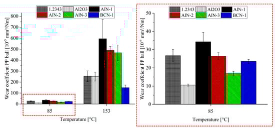
Figure 5.
Wear coefficient of the PP counter balls after the sliding against the AlN-1, AlN-2, AlN-3, and BCN-1 thin films, as well as the steel substrate and the Al2O3 coating, at 85 and 153 °C.
At 153 °C, an increased wear coefficient of the PP balls is detected, compared to the tribological tests at 85 °C. The wear coefficient of the PP balls is increased by the factor 10 to 20, since the mechanical properties of the PP balls are reduced at elevated temperatures. Analyzing the wear coefficient at 153 °C, the differences between the counter parts become more visible compared to 85 °C. The PP balls slid against the steel surface reveal a wear coefficient of 253.7 ± 48.7× 10⁻⁵ mm³/Nm, which is comparable to a wear coefficient of 250.3 ± 41.0 × 10⁻⁵ mm³/Nm for the Al2O3 coating. A lower coefficient of 149.9 ± 22.9 × 10⁻⁵ mm³/Nm is obtained for the BCN-1 counterpart, and higher wear coefficients between 467.0 ± 70.5 × 10⁻⁵ mm³/Nm (AlN-3) and 594.8 ± 175.2 × 10⁻⁵ mm³/Nm (AlN-1) for the AlN thin films. The used PP counter ball is a non-polar plastic, revealing a low fraction of polar surface energy. Accordingly, only the disperse fraction of the free surface energy influences the adhesion behavior to the PP counterpart [33]. Theiss et al. reported that the work of adhesion to PP, which is calculated based on the surface energies, is higher for AlN-rich thin films compared to steel [34]. Especially, for thin films grown in the hexagonal structure, a high work of adhesion is observed [34]. Accordingly, the higher wear of the PP balls slid against the AlN thin films compared to the steel counter body can be related to the surface energies. Moreover, this mechanism is overlaid with the surface roughness. As listed in Table 2, the used deposition parameters of the AlN thin films lead to a change in the roughness. The roughness Ra varies between 0.26 ± 0.06 µm (AlN-3) and 0.36 ± 0.06 µm (AlN-1). The wear of the balls decreases with decreasing roughness in the order AlN-1, AlN-2, AlN-3.
Summarized, within the AlN thin films, the deposition parameters influence the friction coefficient and the wear coefficient of the PP balls at 85 °C, as well as 153 °C. At 153 °C, the influence of the deposition parameters of the AlN thin films on the friction coefficient is lower compared to the wear coefficient. Concerning the wear coefficient at 153 °C, the wear of the PP balls is more influenced by the counter body material than the used deposition parameters of a coating, since the difference between the different materials is higher than the difference within the AlN thin films.
Corresponding SEM images of the adhesions from the PP balls to the different coatings after the test at 85 °C are shown in Figure 6. No adhesion of PP to the surface of the uncoated 1.2343 substrate can be observed. In addition, no adhesions to the Al2O3, AlN-3, and BCN-1 surfaces have occurred. In contrast to that, local PP accumulations are observed on the AlN-1 and AlN-2 thin films, whereas the amount adhered to the AlN-1 thin film is slightly higher. On the one hand, the adhesion to these thin films can be explained by the cauliflower-like surface, resulting in a higher surface roughness in contrast to the other coatings, as shown in Figure 2. On the other hand, the adhesive layer is only observed for the AlN thin films featuring a small fraction of a second phase, as discussed in Section 3.1.1.
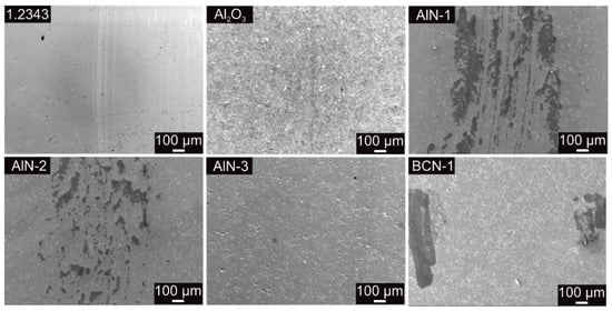
Figure 6.
SEM images of the different surfaces after the Ball-on-Disc experiments at 85 °C.
SEM images of the different surfaces after the Ball-on-Disc experiments at 153 °C are visualized in Figure 7. In contrast to the surfaces analyzed at 85 °C, at 153 °C for all coatings, no rubbing of the PP balls on the surfaces can be noted, which could be related to the change in properties of the PP material with increasing temperature. At 85 and 153 °C, there is no general correlation between the ball wear coefficients and the formation of an adhesive layer. However, the formation of the adhesive layer on the AlN-1 and AlN-2 thin films at 85 °C correlates with the highest ball wear rates within the three AlN thin films.
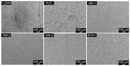
Figure 7.
SEM images of the different surfaces after the Ball-on-Disc experiments at 153 °C.
Furthermore, the influence of the different coating surfaces on the melt flow was investigated at higher temperatures corresponding to the extrusion process. Therefore, the coatings were analyzed in a High-Pressure Capillary Rheometer (HPCR). By means of coated surfaces of specially designed exchangeable inserts, the influence on the flow properties of the melt was investigated. Figure 8 shows the basic setup of the capillary and the coated inserts on the example of the AlN-3 thin film.
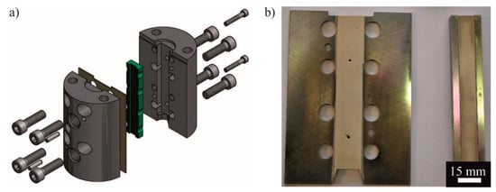
Figure 8.
(a) Setup High-Pressure Capillary Rheometer and (b) coated exchangeable inserts with AlN-3.
Flow anomalies, which are due to the different surface qualities based on the compositions of the coatings, can be detected with a so called “critical” wall shear stress. Until the critical wall shear stress is reached, the melt flow behavior is like “wall sticking”. Therefore, flow anomalies cannot be detected. The onset of the throughput jump depends on, among other things, the melt temperature and the polymer type. In the transition area above the critical wall shear stress, the throughput multiplies many times over, while the wall shear stress remains constant. This range is also referred to as the limiting wall shear stress. Above a certain shear rate, the wall shear stress increases again and the effect of sliding occurs.
Figure 9 shows for the two operating temperatures of 230 and 250 °C and the obtained values of the shear rate in dependence of the shear stress using HPCR. Both diagrams show a steady increase of the shear rate over the wall shear stress. A comparison of the coated measurement curves with the reference measurement (grey curve with squares) shows no significant differences. Minimal deviations between the curves are found and can be attributed to the used setup. From the obtained values, it is concluded that no particular flow anomalies can be detected with the surface coatings present. A critical wall shear stress cannot be detected at the typical shear rates in the extrusion process . Consequently, all investigated coatings can be used as top layers for the thermocouples, since there is no difference in the melt flow behavior between the uncoated and coated surfaces of the wide-slot nozzle.
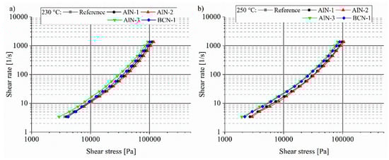
Figure 9.
Critical wall shear stress at (a) 230 °C and (b) 250 °C, independent of the thin film.
3.2. Insertable Thin Film Thermocouple
The insertable thin film thermocouple is designed to be exchangeable, applicable to plastic film extrusion dies. As shown in Figure 10, the unity consists of a bush, which can be screwed into any die revealing an appropriate drilling (M24). The ceramic insert contains the thin film thermocouple and can be inserted into the bush, and is fixed by a step on the bottom side and a cap on the top side. The total length of the screw-in bush, including the top cap, is 63.5 mm.
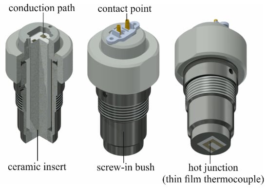
Figure 10.
Structure of the exchangeable thin film thermocouple.
The Ni and Ni-20Cr conducting paths (width of 0.5 mm), deposited on the ceramic insert using a masking system, are shown in Figure 11. On the bottom side (step), the conducting paths are connected to form the hot junction length of 1.5 mm. The conducting paths run over the lateral surface to the top side. On the top side, the conducting paths end with contact points (2.5 × 2.5 mm2), as visualized in Figure 10. Thermocouple balancing lines can be connected to these points, either by brazing or spring probe pins, to conduct the generated thermovoltage to the measuring system.
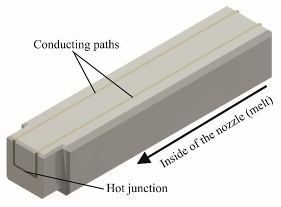
Figure 11.
Ceramic insert showing the conducting paths of the Ni/Ni-20Cr thin film thermocouple.
The multilayer design of the thermally coated insert is shown in Figure 12. Primarily, the steel core is coated with a bond coat (NiCoCrAlTaY) to enhance the adhesion of the ceramic layers to the steel substrate, especially at higher temperatures. The bond coat is followed by a coarse 7Y2O3-ZrO2 coating to ensure the thermal insulation between the thin film thermocouple and the die, as well as the steel core of the insert, for an accurate measurement of the temperature of the plastic melt variations. Especially for wall mounted thermocouples, it is reported that the measurement of temperature fluctuations is difficult when the thermal insulation is not adequate [10]. The 7Y2O3-ZrO2 coating is layered by a dense Al2O3 coating, which improves the adhesion of the thin film thermocouples due to a lower content of defects, such as pores. Moreover, Al2O3 reveals a higher electrical resistance compared to ZrO2 to guarantee no electrical short of the thermocouple.
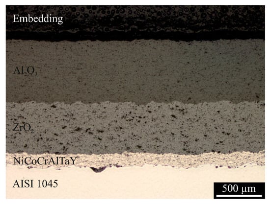
Figure 12.
Cross-section of the multilayer design of the thermally sprayed insulating coatings of the ceramic insert.
The extrusion nozzle is made of steel and, therefore, the inserted tool with the thin film thermocouple should reveal the same tribological properties. As shown by the Ball-on-Disc experiments, all coatings reveal no adhesions of the PP counter ball on the surface at 153 °C. Concerning the wear of the PP ball, similar values are obtained for the steel surface and the thermally sprayed Al2O3 coating. High-Pressure Capillary Rheometer experiments also demonstrate no significant differences in the melt flow for the different coatings. Therefore, the thin film thermocouple was not covered by an additional nitride layer for the operation test.
3.3. Operation Test
3.3.1. Validation of the Temperature Measurement
Before the operational testing, the calibration curves for the thermocouples have to determined. In a previous study [20], the procedure was described and the dependence of the thermovoltage and temperature for the thermocouples was found. In the present study, the mass temperature was measured shortly before the outlet of the die. The used experimental setup is shown in Figure 13.
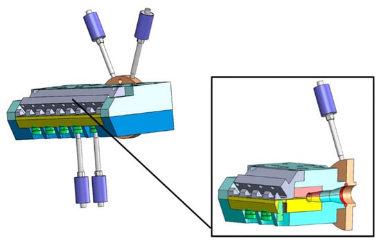
Figure 13.
Experimental setup showing the array of the thermocouples in the wide-slit nozzle.
After the extrusion line reached a steady state for the cylinder heating and the used material, the embedded thin film thermocouple (TE) was inserted in the die and the recording of the measurement signal began. All four elements were inserted at the same time. Figure 14 shows the heating process of the thermocouple (grey line) until a static state was reached. All other temperature sensors were installed in advance to check the tool temperature. In total, the thermocouple required 130 s until 90% of the final value was reached, and approximately 1000 s until the stationary state was reached.
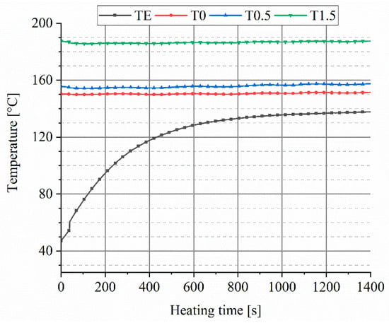
Figure 14.
Heating curve of the thin film thermocouple in the plastic flat film extrusion process.
After the steady state of the thermocouple was reached, the measurement with all sensors was recorded over a time of 1.5 h. The measurement of the melt temperature at the mold outlet was additionally determined in 5 min intervals by means of a thermocouple as a guideline value. The surface temperature was also measured with a laser to verify the values. Figure 15 shows the temperature curve over time.
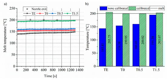
Figure 15.
(a) Monitor conditioning of the melt temperature and (b) influence of the calibration on the measured mass temperature.
During the measuring process, no temperature peaks were detected (Figure 15a). All sensors displayed a constant measuring signal within the time interval. Due to the measuring tip of the T1.5, the sensor was placed deeper in the melt and measured the melt temperature significantly better. These measured values and the mathematical equations for the calibration curves were used to adjust accuracy of the measured melt temperatures. Figure 15b shows the adjusted temperatures. All thermocouples show relatively similar measured values after calibration. Compared to the mass temperature of 200.6 °C obtained by a laser at the nozzle exit, the sensors T0 and T0.5 measure with the lowest deviation after calibration. The deviation of the thin film thermocouple is 2.52%. Especially in polymer extrusion, the determination of the temperature is important, since even small deviations lead to a high change of the shear viscosity of the melt [35]. However, all used thermocouples, including the thin film thermocouple, can be used for the temperature monitoring of the mass in the extrusion die process after recalibration regarding the mounting place in the nozzle. Before the recalibration, the accuracy of the measured mass temperature increased with extent into the melt. For obtaining die melt temperature profiles in extrusion processes, generally, thermocouple mesh arrangements are inserted in the melt flow [10]. However, this technique can only be used in test conditions, since the melt flow is disturbed. Using many thin film thermocouples, a temperature profile can be obtained without affecting the melt flow.
3.3.2. Foil Quality
The optical film properties were determined by measuring gloss and transmission. Ten samples (dimensions 50 × 100 mm2) were taken for evaluation during flat film production. The transmission and the gloss of the films were tested based on the described experimental setup. For the transmission, the determination of the light intensity I0 is necessary as reference. The transmitted light intensity IT was measured by clamping the samples in the sample holder. The difference between I0 and IT is the transmission spectrum. For the reflection, a white comparison sample is required, which completely reflects the entire light intensity I0. Ocean Optics provided white specimens for the comparison sample. Then, the samples were irradiated with the light intensity I0 at the angle of 2° defined in DIN 5036-3, and the reflected part IR was measured.
Table 3 shows the reflection results for settings 1 and 2 as reflectance [%]. The velocity of the trigger unit was changed between the two settings. While at setting 1, the velocity reaches 1.5 mm/s, at setting 2 the velocity is 1.7 mm/s. For both settings, the values are between 29.91% and 31.88% and, accordingly, there is no significant difference between the different sensors. The wall-flush thermal sensors and the thin film thermocouples have a slightly lower value than the others.
Table 3.
Results of the reflection results in dependence of the used thermocouple.
Table 4 shows the transmission results for settings 1 and 2 as transmittance [%]. There are no significant differences in the settings. Therefore, the geometry of the thermocouples does not influence the transmittance. Only for setting 2, the measured values are 5% higher than setting 1. This effect is to be explained due to the fact that setting 2 produces thinner films, and an increased light intensity penetrates the sample.
Table 4.
Results of the transmission results in dependence of the used thermocouple.
4. Conclusions
In this study, AlN and BCN thin films were magnetron sputtered on thermally sprayed Al2O3 coatings using different deposition parameters. In the case of the AlN thin films, a high Ar/N2 gas flow ratio of 6.0 and a high heating power led to a coarse structure with a reduced hardness from about 14 to 6 GPa. Since these films are proposed to be used in flat film extrusion nozzles, tribological experiments were conducted. Using a high deposition temperature and high Ar/N2 gas flow ratio for the AlN coatings favor the adhesion of Polypropylen to the thin film surfaces after Ball-on-disc experiments at 85 °C. The formation of the adhesive layer is caused by the higher roughness of the AlN thin films, which can be related to the physical structure, and the work of adhesion. In contrast, no adhesions to the steel surface, the thermally sprayed Al2O3 coating, the BCN thin film, or a AlN thin deposited with lower temperature and higher Ar/N2 gas flow ratio were observed. At 153 °C, for all coatings, no adhesions emerged, since the mechanical properties of the PP ball were changed with the temperature. The interaction of the thin film thermocouples with the plastic melt was investigated in application tests. Compared to the uncoated tool surface, the thin films reveal no negative effects on the wall shear stress and the wall shear speed. Accordingly, an effect of the thermocouple on the foil quality could not be detected in the samples examined under the spectroscope. Thus, flat films with constant reflection properties could be produced by measuring the melt temperature using thin film thermocouples.
Ni/Ni-20Cr thin film thermocouples were deposited on newly developed exchangeable tool inserts and deployed in a flat film extrusion process. The measurement signal of the thin film thermocouple and industrial reference thermocouples were tested using a specially designed die. No temperature peaks were detected during the measuring process, demonstrating a stable measurement behavior. At a melt temperature value of 200.57 °C, the obtained value by the help of the thin film thermocouple was 205.75 °C, which is slightly higher compared to the industrial sensors. The deviation of the thin film thermocouple did not exceed 2.52%, which is within a typical tolerance range of a type K sensor. Within the proposed attempt, PVD thermocouples are a promising approach which can be used for online monitoring. However, the used design can be used to further enhance the performance of the wide-slit nozzle by using wear resistant top layers.
Author Contributions
Conceptualization, D.K., H.M. and D.S.; Methodology, D.K. and H.M.; Validation, D.K., H.M. and D.S.; Investigation, D.K. and H.M.; Writing—Original Draft Preparation, D.K. and H.M.; Writing—Review and Editing, W.T., D.S. and V.S.; Supervision, W.T. and V.S.; Funding Acquisition, W.T. and V.S.
Funding
The authors gratefully acknowledge the financial support of project 18627 N of the German Federation of Industrial Research Associations (AiF) and the Forschungskuratorium Maschinenbau e.V. (FKM).
Acknowledgments
We acknowledge financial support by Deutsche Forschungsgemeinschaft and Technische Universität Dortmund/TU Dortmund University within the funding programme Open Access Publishing. In addition, the authors thank Dirk Biermann and Eugen Krebs from the Institute of Machining Technology (TU Dortmund University) for machining the ceramic inserts and providing the confocal 3D microscope.
Conflicts of Interest
The authors declare no conflicts of interest.
References
- Lee, J.; Kao, H.-A.; Yang, S. Service innovation and smart analytics for industry 4.0 and big data environment. Procedia CIRP 2014, 16, 3–8. [Google Scholar] [CrossRef]
- Yust, M.; Kreider, K.G. Transparent thin film thermocouple. Thin Solid Films 1989, 176, 73–78. [Google Scholar] [CrossRef]
- Marr, M.A.; Wallace, J.S.; Chandra, S.; Pershin, L.; Mostaghimi, J. A fast response thermocouple for internal combustion engine surface temperature measurements. Exp. Therm. Fluid Sci. 2010, 34, 183–189. [Google Scholar] [CrossRef]
- Tougas, I.M.; Gregory, O.J. Thin film platinum–palladium thermocouples for gas turbine engine applications. Thin Solid Films 2013, 539, 345–349. [Google Scholar] [CrossRef]
- Zhao, J.; Li, H.; Choi, H.; Cai, W.; Abell, J.A.; Li, X. Insertable thin film thermocouples for in situ transient temperature monitoring in ultrasonic metal welding of battery tabs. J. Manuf. Process. 2013, 15, 136–140. [Google Scholar] [CrossRef]
- Basti, A.; Obikawa, T.; Shinozuka, J. Tools with built-in thin film thermocouple sensors for monitoring cutting temperature. Int. J. Mach. Tools Manuf. 2007, 47, 793–798. [Google Scholar] [CrossRef]
- Biermann, D.; Kirschner, M.; Pantke, K.; Tillmann, W.; Herper, J. New coating systems for temperature monitoring in turning processes. Surf. Coat. Technol. 2013, 215, 376–380. [Google Scholar] [CrossRef]
- Shinozuka, J.; Basti, A.; Obikawa, T. Development of cutting tool with built-in thin film thermocouples for measuring high temperature fields in metal cutting processes. J. Manuf. Sci. Eng. 2008, 130, 34501. [Google Scholar] [CrossRef]
- Tillmann, W.; Vogli, E.; Herper, J.; Biermann, D.; Pantke, K. Development of temperature sensor thin films to monitor turning processes. J. Mater. Process. Technol. 2010, 210, 819–823. [Google Scholar] [CrossRef]
- Abeykoon, C.; Martin, P.J.; Kelly, A.L.; Brown, E.C. A review and evaluation of melt temperature sensors for polymer extrusion. Sensors Actuators A Phys. 2012, 182, 16–27. [Google Scholar] [CrossRef]
- Debey, D.; Bluhm, R.; Habets, N.; Kurz, H. Fabrication of planar thermocouples for real-time measurements of temperature profiles in polymer melts. Sensors Actuators A Phys. 1997, 58, 179–184. [Google Scholar] [CrossRef]
- Marshall, R.; Atlas, L.; Putner, T. The preparation and performance of thin film thermocouples. J. Sci. Instrum. 1966, 43, 144–149. [Google Scholar] [CrossRef]
- Yang, L.; Zhao, Y.; Feng, C.; Zhou, H. The influence of size effect on sensitivity of Cu/CuNi thin- film thermocouple. Phys. Procedia 2011, 22, 95–100. [Google Scholar] [CrossRef][Green Version]
- Chen, Y.; Jiang, H.; Zhao, W.; Zhang, W.; Liu, X.; Jiang, S. Fabrication and calibration of Pt–10%Rh/Pt thin film thermocouples. Measurement 2014, 48, 248–251. [Google Scholar] [CrossRef]
- Bhatt, H.D.; Vedula, R.; Desu, S.B.; Fralick, G.C. Thin film TiC/TaC thermocouples. Thin Solid Films 1999, 342, 214–220. [Google Scholar] [CrossRef]
- Tian, X.; Kennedy, F.E.; Deacutis, J.J.; Henning, A.K. The development and use of thin film thermocouples for contact temperature measurement. Tribol. Trans. 1992, 35, 491–499. [Google Scholar] [CrossRef]
- Shinozuka, J.; Obikawa, T. Development of cutting tools with built-in thin film thermocouples. Key Eng. Mater. 2004, 257–258, 547–552. [Google Scholar] [CrossRef]
- Lüthje, H.; Bandorf, R.; Biehl, S.; Stint, B. Thin film sensor for wear detection of cutting tools. Sensors Actuators A Phys. 2004, 116, 133–136. [Google Scholar] [CrossRef]
- Seibel, S. Vielfalt am laufenden Meter. Kunststoffe 2005, 12, 38–46. [Google Scholar]
- Michaeli, W. Extrusions-Werkzeuge für Kunststoffe und Kautschuk. Bauarten, Gestaltung und Berechnungsmöglichkeiten; Hanser: München, Germany, 1991; ISBN 3446156372. [Google Scholar]
- Tillmann, W.; Kokalj, D.; Stangier, D. Optimization of the deposition parameters of Ni-20Cr thin films on thermally sprayed Al2O3 for sensor application. Surf. Coat. Technol. 2018, 344, 223–232. [Google Scholar] [CrossRef]
- Tillmann, W.; Kokalj, D.; Stangier, D.; Schöppner, V.; Benis, H.B.; Malatyali, H. Influence of Cr-Content on the thermoelectric and mechanical properties of NiCr thin film thermocouples synthesized on thermally sprayed Al2O3. Thin Solid Films 2018, 663, 148–158. [Google Scholar] [CrossRef]
- Oliver, W.C.; Pharr, G.M. An improved technique for determining hardness and elastic modulus using load and displacement sensing indentation experiments. J. Mater. Res. 1992, 7, 1564–1583. [Google Scholar] [CrossRef]
- DIN EN ISO 26443 German Institute for Standardization. Fine Ceramics (Advanced Ceramics, Advanced Technical Ceramics)—Rockwell Indentation Test for Evaluation of Adhesion of Ceramic Coatings; Beuth Verlag GmbH: Berlin, Germany, 2016. [Google Scholar]
- Hochrein, T.; Alig, I. Prozessmesstechnik in der Kunststoffaufbereitung, 1st ed.; Vogel Business Media: Würzburg, Germany, 2011; ISBN 9783834331175. [Google Scholar]
- Ait Aissa, K.; Achour, A.; Camus, J.; Le Brizoual, L.; Jouan, P.-Y.; Djouadi, M.-A. Comparison of the structural properties and residual stress of AlN films deposited by dc magnetron sputtering and high power impulse magnetron sputtering at different working pressures. Thin Solid Films 2014, 550, 264–267. [Google Scholar] [CrossRef]
- Choudhary, R.K.; Mishra, S.C.; Mishra, P.; Limaye, P.K.; Singh, K. Mechanical and tribological properties of crystalline aluminum nitride coatings deposited on stainless steel by magnetron sputtering. J. Nucl. Mater. 2015, 466, 69–79. [Google Scholar] [CrossRef]
- Bagcivan, N.; Bobzin, K.; Theiß, S. (Cr1−xAlx)N: A comparison of direct current, middle frequency pulsed and high power pulsed magnetron sputtering for injection molding components. Thin Solid Films 2013, 528, 180–186. [Google Scholar] [CrossRef]
- Bobzin, K.; Nickel, R.; Bagcivan, N.; Manz, F.D. PVD-coatings in injection molding machines for processing optical polymers. Plasma Process. Polym. 2007, 4, S144–S149. [Google Scholar] [CrossRef]
- Silva, F.J.G.; Martinho, R.P.; Baptista, A.P.M. Characterization of laboratory and industrial CrN/CrCN/diamond-like carbon coatings. Thin Solid Films 2014, 550, 278–284. [Google Scholar] [CrossRef]
- Tillmann, W.; Hagen, L.; Hoffmann, F.; Dildrop, M.; Wibbeke, A.; Schöppner, V.; Resonnek, V.; Pohl, M.; Krumm, C.; Tiller, J.C.; et al. The detachment behavior of polycarbonate on thin films above the glass transition temperature. Polym. Eng. Sci. 2016, 56, 786–797. [Google Scholar] [CrossRef]
- Goryacheva, I.G. Contact Mechanics in Tribology; Springer: Dordrecht, The Netherlands, 1998; ISBN 9789048151028. [Google Scholar]
- Lugscheider, E.; Bobzin, K. The influence on surface free energy of PVD-coatings. Surf. Coat. Technol. 2001, 142–144, 755–760. [Google Scholar] [CrossRef]
- Theiß, S. Analyse Gepulster Hochleistungsplasmen zur Entwicklung Neuartiger PVD-Beschichtungen für die Kunststoffverarbeitung; Shaker: Aachen, Germany, 2013; ISBN 9783844021127. [Google Scholar]
- Vera-Sorroche, J.; Kelly, A.; Brown, E.; Coates, P.; Karnachi, N.; Harkin-Jones, E.; Li, K.; Deng, J. Thermal optimisation of polymer extrusion using in-process monitoring techniques. Appl. Therm. Eng. 2013, 53, 405–413. [Google Scholar] [CrossRef]
© 2019 by the authors. Licensee MDPI, Basel, Switzerland. This article is an open access article distributed under the terms and conditions of the Creative Commons Attribution (CC BY) license (http://creativecommons.org/licenses/by/4.0/).