Article

Fabrication of Ni–Co–BN (h) Nanocomposite Coatings with Jet Electrodeposition in Different Pulse Parameters

1
College of Engineering, Nanjing Agricultural University, Nanjing 210031, China
2
College of Mechanical and Electrical Engineering, Suzhou University, Suzhou 234000, Anhui, China
3
Key Laboratory of Spin Electron and Nanomaterials of Anhui Higher Education Institutes, Suzhou University, Suzhou 234000, Anhui, China
4
Guanyun Research Institute for Modern Agricultural Equipment, Nanjing Agricultural University, Guanyun 222200, China
*
Author to whom correspondence should be addressed.
Coatings 2019, 9(1), 50; https://doi.org/10.3390/coatings9010050
Submission received: 1 October 2018 / Revised: 5 December 2018 / Accepted: 14 January 2019 / Published: 16 January 2019
(This article belongs to the Special Issue Nanocomposite Coatings)

Abstract

:
In order to study the effects of pulse parameters on jet electrodeposition, Ni–Co–BN (h) nanocomposite coatings were prepared on the surface of steel C1045. The samples were analyzed and characterized by scanning electron microscopy (SEM), energy dispersive spectroscopy (EDS), X-ray diffraction (XRD), laser scanning confocal microscopy (LSCM), microhardness tester, and electrochemical workstation. The experimental results showed that the contents of Co and BN (h) nanoparticles in the coatings changed with the variation of pulse parameters. When the pulse frequency was 4 kHz and the duty cycle was 0.7, their contents reached maxima of 27.34 wt % and 3.82 wt %, respectively. The XRD patterns of the coatings showed that the deposits had a face-centered cube (fcc) structure, and there was an obvious preferred orientation in (111) plane. With the increase in pulse parameters, the surface roughness of the coatings first decreased and then increased, with the minimum value obtained being 0.664 µm. The microhardness of the coatings first increased and then decreased with increase in pulse parameters. The maximum value of the microhardness reached 719.2 HV0.05 when the pulse frequency was 4 kHz and the duty cycle was 0.7. In the electrochemical test, the potentiodynamic polarization curves of the coatings after immersion in 3.5 wt % NaCl solution showed the pulse parameters had an obvious effect on the corrosion resistance of the Ni–Co–BN (h) nanocamposite coatings. The corrosion current density and polarization resistance indicated that the coatings had better corrosion resistance when the pulse frequency was 4 kHz and duty cycle was 0.7.

1. Introduction

Wear and corrosion are the most common types of failure in parts. The wear and corrosion processes are gradual and not very distinct thereby making it hard for people to easily notice them. Therefore, they usually have huge negative effects in the industry and daily life due to lowering of operational efficiency of machines. According to the relation reports, annul economic losses caused only by corrosion damage in the world exceed that due to natural disasters. The unique volume effect and surface effect of nanomaterials have great development potential and application prospects in new materials and functional materials. Embedding nanoparticles into the nanocomposite materials can optimize the microstructure and improve the mechanical properties. Also, new functional properties may also be observed from the nanocomposite materials. Ni–Co alloys have high hardness, excellent wear resistance and corrosion resistance. They are often coated on the surface of parts as protective materials to improve the surface properties. In recent years, the research and exploration of Ni–Co alloy coatings has always been the focus of attention for scholars. The preparation and properties of Ni–Co nanocomposite coatings with different nanoparticles (SiC [1,2], SiO2 [3], Al2O3 [4,5,6], ZrO2 [7,8,9], TiO2 [10,11], CNT [12], etc.) as the second phase have been reported. BN (h) nanoparticles have excellent performances in electrical insulating, thermal stability, chemical stability, and self-lubrication. Its advantages in biomedical applications [13,14], microelectronics [15], nanophotonics [16], composite materials [17], electrochemical catalysis [18], hydrogen storage materials and fuel cells [19,20] have been discovered and preliminarily applied. The Ni–Co composite coatings having BN (h) as the second phase has better properties in self-lubricating and wear resistance, high temperature resistance, and corrosion resistance. Therefore, the studies about Ni–Co–BN (h) nanocomposite coatings have important significance in the improvement of material surface properties.
Electrodeposition technology has the advantages of controllable deposition process and better coatings thickness. It is one of the common methods used to prepare metal coatings. Pulse electrodeposition is a method of electrodeposition in which the circuit controlling current is switched on and off periodically, or a pulse waveform is superimposed on a fixed DC. In the process of pulse electrodeposition, the relaxation of current or voltage can not only weaken the concentration polarization of the cathode, but can also produce adsorption and desorption effects on the cathode surface. In addition, periodic interruption of the circuit can prevent the continuous growth of grains and refine the grain size. The above characteristics of pulse electrodeposition made it possible to obtain higher deposition efficiency, smaller grain size, and had obvious advantages in improving coatings performances and saving precious metals [9,21]. Figure 1 shows a schematic image of the jet electrodeposition device. As shown in Figure 1, jet electrodeposition is a technique in which the sample is used as the cathode and the nozzle as the anode. Under the action of an electric field, the plating solution is sprayed from the nozzle to the cathode surface to achieve electrodeposition. Compared with traditional electrodeposition, it can allow for a higher over-potential in the deposition process and has a higher deposition efficiency. The periodic sweeping of the nozzle relative to the cathode could continuously change the deposition area, thereby preventing the continuous growth of the grains and refining the grain size [22,23,24]. With the help of the numerical control device, the jet electrodeposition can also obtain coatings on the surface of parts with different shapes and sizes. These characteristics enable it to have good application prospects in the preparation of nanocrystalline materials and local repair of parts surface [24].
In order to study the effects of pulse parameters on the properties of Ni–Co–BN (h) nanocomposite coatings, Ni–Co–BN (h) nanocomposite coatings were prepared by jet electrodeposition with different pulse parameters. The surface morphology and cross-section images, composition, phase structure, surface roughness, microhardness and corrosion resistance of Ni–Co–BN (h) composite coatings were characterized and analyzed by SEM, EDS, XRD, LSCM, microhardness tester, and electrochemical workstation, respectively. The above tests and analysis results may be useful to provide theoretical reference for industrial production and practical application of pulse jet electrodeposition technology.

2. Experimental

2.1. Experimental Materials and Pretreatment

A steel C1045 sample with a size of 7 mm × 8 mm × 30 mm was used as substrate and a high purity nickel plate (99.9%) was used as anode nozzle in the pulse jet electrodeposition process. The aperture of the nozzle was a 10 mm × 1 mm rectangle. The steel C1045 substrate was activated by DC power source after degreasing and polishing. In the activation process, the residual oil contamination on the substrate surface was removed by electric cleaning solution. In the process of electric cleaning, the substrate was connected to the negative electrode and the high purity nickel plate was connected to the positive electrode. The treatment current was 1 A, and the processing time was 20 s. After electric cleaning treatment, the substrate was connected to the positive electrode, and the high purity nickel plate to the negative electrode then immersed into strong activation solution for strong activation treatment. The strong activation current was 0.5 A and the treatment time was 30 s. Finally, the same activation mode with strong activation was used for weak activation in weak activated solution. The weak activation current was 0.5 A and the treatment time was 20 s. The different solution constituents for this paper are shown in Table 1. The grade of all the chemicals was analytically pure, and the solvent and cleaning solution used in the experiments was deionized water. After the plating solution was prepared, the pH value of the solution was adjusted to 4.3 by NaOH and HCl. The BN (h) nanoparticles size added in the plating solution was 100 nm and the concentration was 5 g L−1.

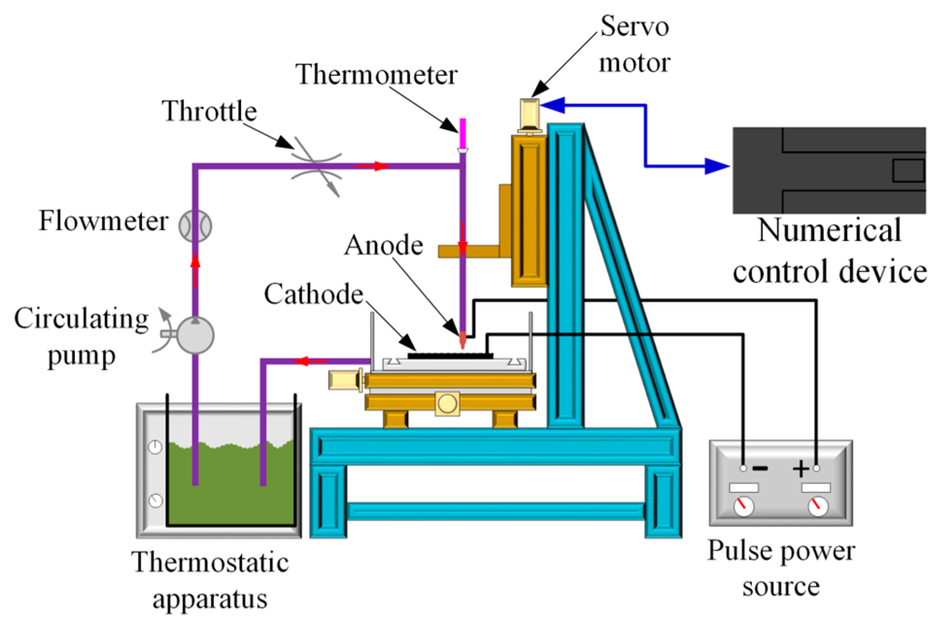
2.2. Preparation of Ni–Co–BN (h) Nanocomposite Coating

The jet electrodeposition was carried out on the self-made experimental facility under the action of pulse power source. The activated steel C1045 substrate was connected to the cathode and the high purity nickel plate was connected to the anode. In the process of preparing Ni–Co–BN (h) nanocomposite coatings, the gap between the nozzle and the cathode was 1.6 mm, the temperature of plating solution was 60 °C, the pulse voltage was 18 V, and the electrodeposition time was 20 min. The speed of the reciprocating sweep of the nozzle relative to the cathode was 135 mm s−1, and the injection speed of the plating solution was 1.5 m s−1. After the process of pulse jet electrodeposition, the samples were cleaned in the ultrasonic cleaner for 5 min.

2.3. Sample Characterization

The surface morphology and thickness of Ni–Co–BN (h) nanocomposite coatings were characterized using scanning electron microscope (SEM, Quanta 250, FEI, Hillsboro, OR, USA). The element content was analyzed using energy dispersive spectrometer (EDS, XFlash Detector 5030, BRUKER, Karlsruhe, Germany). The phase structure of the samples was measured by X-ray diffraction (XRD, X’Pert Powder, PANalytical B.V., Almelo, Holland). Laser scanning confocal microscope (LSCM, OLS4000, OLYMPUS, Tokyo, Japan) was used to measure the surface roughness of the coatings. The average surface roughness at five different positions was determined. The microhardness of the coatings was measured by microhardness tester (HVS-1000, Laizhou Huayin Test Instrument Co., Ltd., Yantai, China). The test load was 50 g, the loading time was 15 s, and the hardness results took the average value of five different points on the coatings surface. The corrosion resistance of the coatings was tested by electrochemical workstation (CS350, Wuhan Corrtest Instruments Corp., Ltd., Wuhan, China) in 3.5 wt % NaCl solution. Before the corrosion resistance test, the samples were immersed into the 3.5 wt % NaCl solution for 2 h to obtain stable test results. The potential range of potentiodynamic sweeping was −0.6 to +0.6 V with respect to EOCV, and the sweeping rate was 0.5 Mv s−1.

3. Results and Discussion

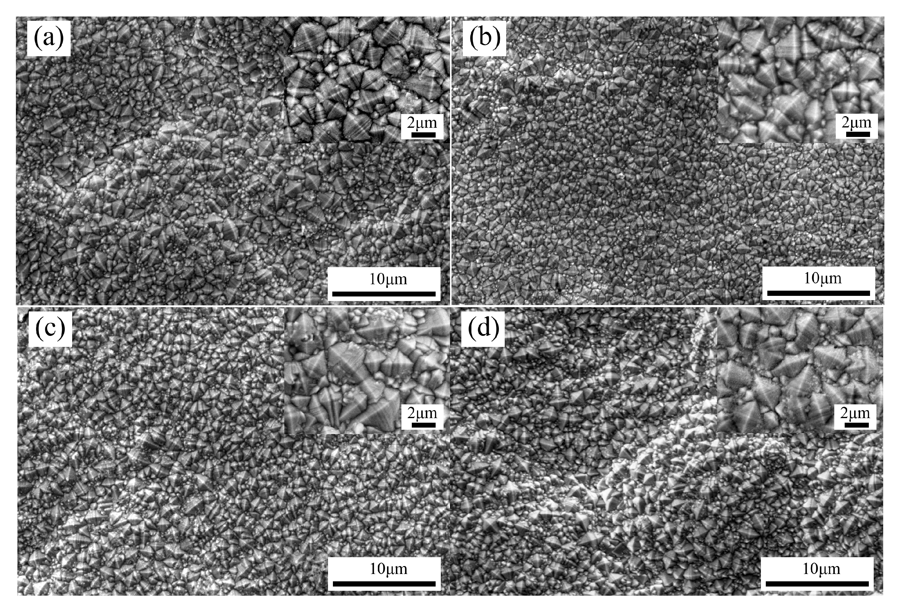
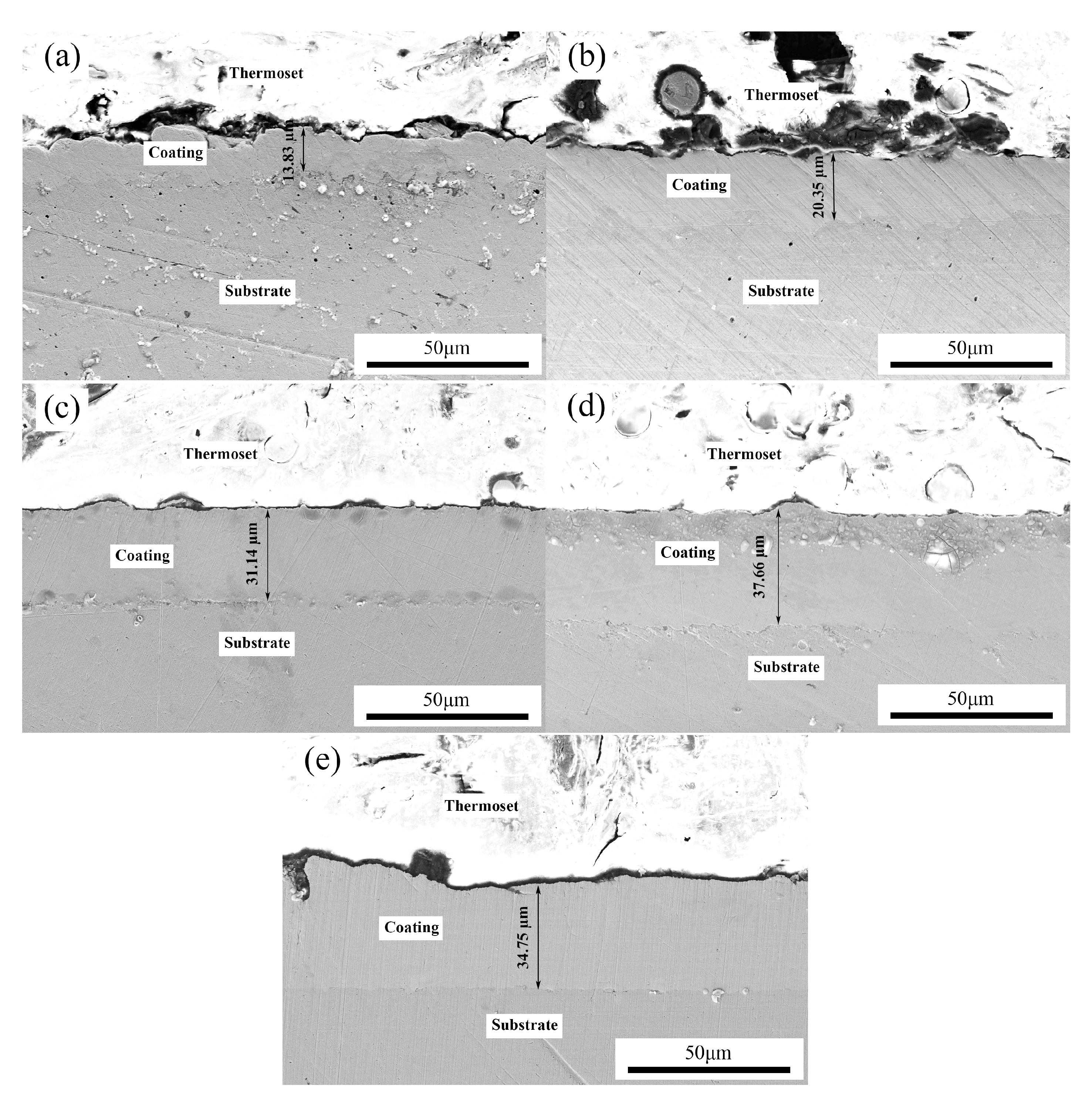
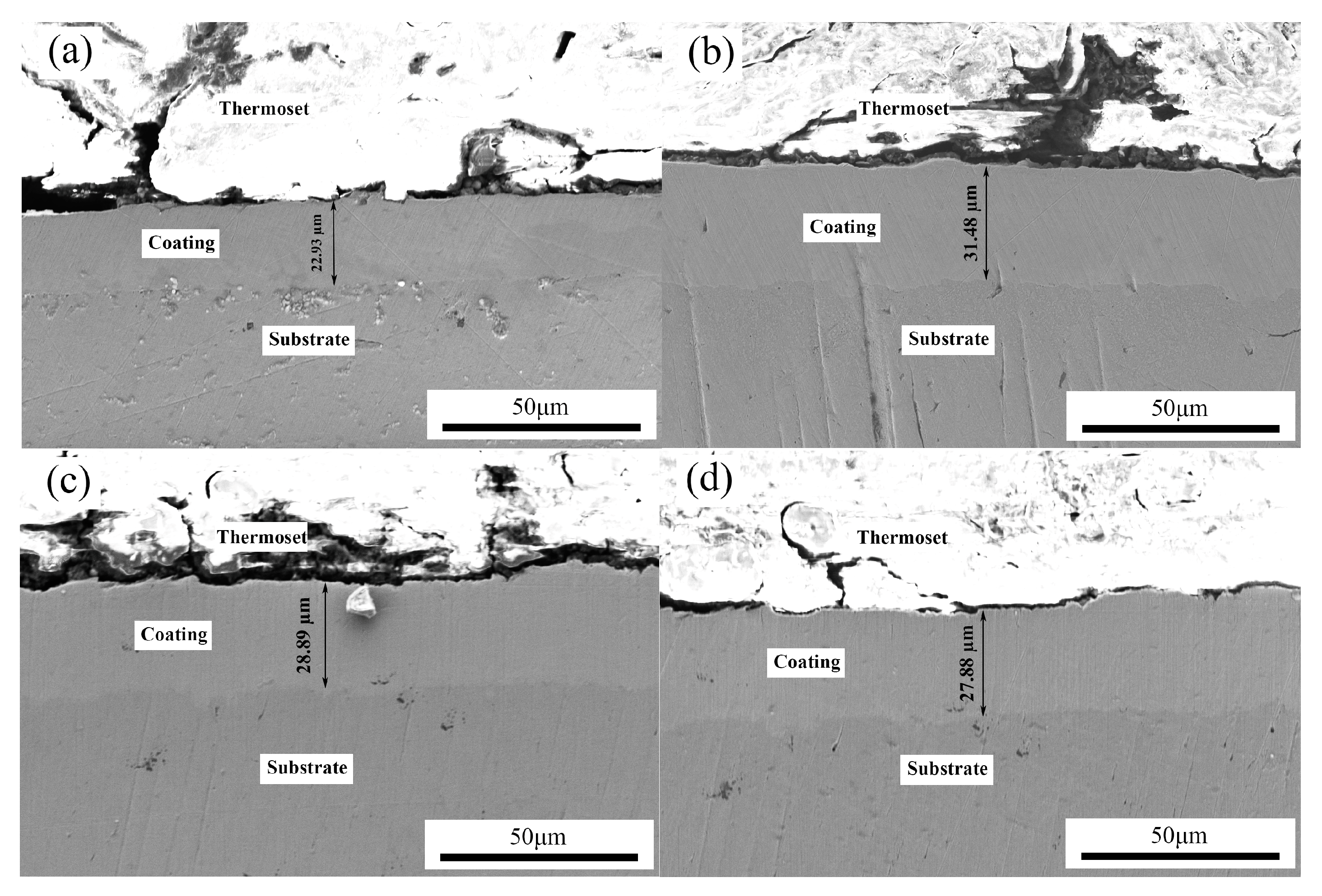
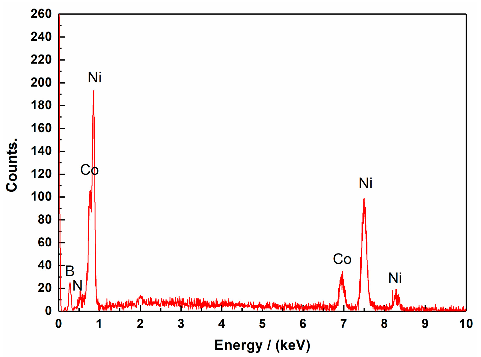
3.1. Effects of Pulse Parameters on the Surface Morphology and Element Content

Figure 2 shows the surface morphologies of Ni–Co–BN (h) nanocomposite coatings with pulse frequency of 4 kHz and varying duty cycles. It can be seen from Figure 2 that the duty cycle has a great influence on the surface morphology of the coatings. When duty cycle was 0.1 (Figure 2a), some different-sized globular protrusions appeared on the coating surface. A deep canyon and a small crack were formed between the adjacent big globular protrusions. As the duty cycle increased (Figure 2a–d), the depth of the canyon gradually decreased and almost disappeared. Further increase in the duty cycle resulted in the depth of the canyon increasing slightly (Figure 2e). Figure 3 shows the surface morphologies of Ni–Co–BN (h) nanocomposite coatings with duty cycle of 0.7 and varying pulse frequencies. The flatness of the coatings surface first increased and then decreased with variation of pulse frequency as shown by Figure 2d and Figure 3a–d. There were a large number of diamond shaped protrusions on the coatings surface as can be seen from Figure 2 and Figure 3. Also, there was no obvious cluster phenomenon of BN (h) nanoparticles on the coating surface.
Figure 4 and Figure 5 show the cross-section images of the Ni–Co–BN (h) nanocomposite coatings with varying pulse parameters. As can be seen from the figures, the coatings thickness changed with the variation of pulse parameters. When the pulse frequency was 4 kHz and the duty cycle was increased (Figure 4a–e), the coatings thickness first increased and then decreased. When the duty cycle was 0.7, the coating obtained a maximum thickness of approximately 37.66 μm. When the duty cycle was 0.7 and the frequency was increased (Figure 4d and Figure 5a–d), the thickness of coatings showed a similar trend with that of the duty cycle. With the increase in pulse frequency, the coatings obtained a maximum thickness at 4 kHz. Because the coatings thickness is an important index for deposition efficiency, better thickness with the same deposition time means that the coating has a better deposition efficiency. Therefore, the change of coatings thickness can reflect the change in the deposition efficiency in electrodeposition. The figures also indicated that the deposits had a compact structure and no obvious stomata were observed in the coatings matrix. The boundary of the substrate and the coating was compact and the coatings matrix was well adhered to the substrate.
Figure 6 shows the EDS spectra of Ni–Co–BN (h) nanocomposite coatings surface with duty cycle of 0.7 and pulse frequency of 4 kHz. Considering the N element in the bath was provided only by the BN (h) nanoparticles, the change of N element content in the coatings directly reflects the change in nanoparticles content. Table 2 shows partial data of Ni–Co–BN (h) nanocomposite coatings with varying pulse parameters. As shown in Table 2, the contents of Co, Ni, and N elements in the coatings changes with the variation of pulse parameters. With the increase in duty cycle, the contents of Co and N elements in the deposit first increased and then decreased. The content of Ni element first decreased and then increased with increase in duty cycle. When duty cycle was 0.7, the contents of Co and N elements reached the maximum, that was 27.34 wt % and 3.82 wt %, respectively. At the same duty cycle, the content of Ni element decreased to a minimum value of 68.84%. When the pulse frequency increased, the contents of Co and N elements in the coatings first increased and then decreased. This content variation trend was similar to the one observed when duty cycle was increased. The content of Ni element first decreased and then increased with increase in frequency. The maximum value of Co and N elements was obtained when the pulse frequency was 4 kHz.
Those results may be due to the periodic effect of the pulse power source. The change of duty cycle and frequency can affect the connection and disconnection time. Reasonable pulse turn-on and turn-off time can make the metal ions consumed in deposition to be timely supplemented. This reduces the concentration polarization of the cathode surface and also aids the cathode surface adsorption and desorption effects. Shorter pulse turn-on time can cause a decrease in grain growth time and lower the deposition efficiency. However, when the pulse turn-on time is extremely long, the consumption of the metal ions on the cathode is extremely high. This can increase the concentration polarization of the cathode surface, which results in rapid hydrogen formation on the cathode surface. The hydrogen layer formed hinders effective deposition of metal ions thereby reducing efficiency. The amount of nanoparticles in the coatings is largely affected by the deposition efficiency. A low deposition efficiency decreases the capturing capacity of the nanoparticles suspended in the plating solution. As a result, the nanoparticles are either loosely adsorbed into the cathode surface or embedded at a much lower content. This results in the reduction of the nanoparticles content in the coatings. In addition, relevant literature studies show that the content of Co in Ni–Co alloy coating can affect the content of nanoparticles [25,26]. The increase in Co content can increase the content of nanoparticle in the coatings.

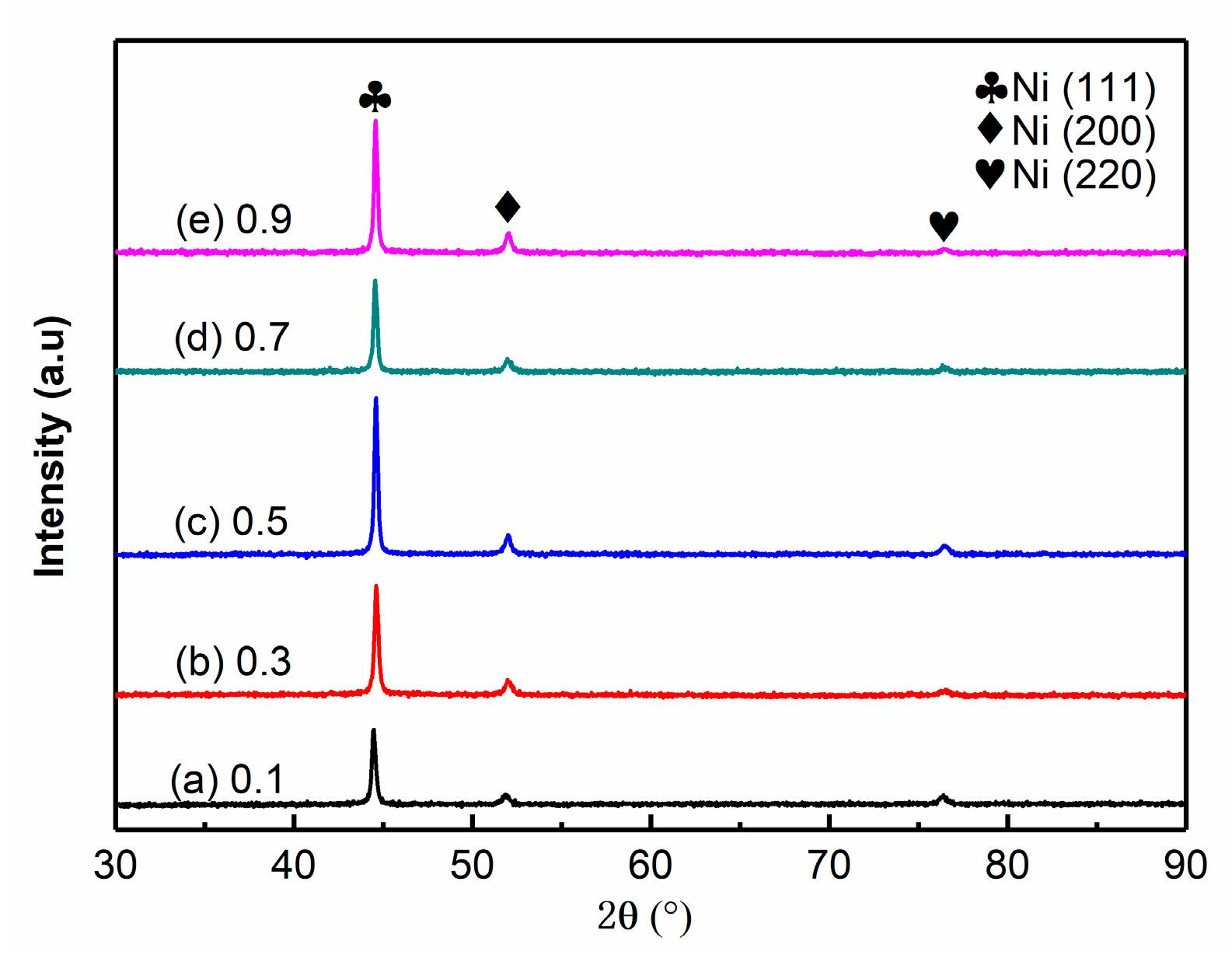
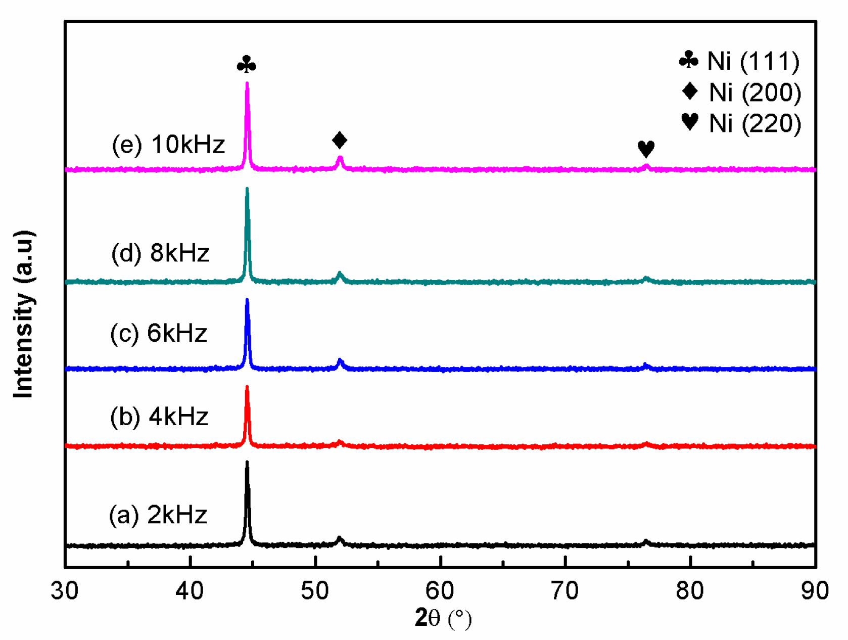
3.2. Effects of Pulse Parameters on the Phase Structure

Figure 7 and Figure 8 show the XRD patterns of Ni–Co–BN (h) nanocomposite coatings with varying pulse parameters. From the figures it can be seen that the Ni–Co–BN (h) nanocomposite coatings have a face-centered cubic (fcc) structure. The 2theta angles corresponding to the (111), (200), and (220) planes were 44.06°, 51.95°, and 76.54°, respectively. The variation of pulse parameters had no obvious effects on the phase structure. Ni atoms and Co atoms formed a Ni–Co solid solution. As a result of the low content of Co in the coatings, the Ni–Co solid solution formed in the coatings was a single α-phase structure [27,28]. Calculation of the texture coefficient indicated a preferred orientation appeared at (111). Probably due to the relatively low content of BN (h) nanoparticles and also being dispersive in the coatings, the related diffraction peaks were not distinct in Figure 7 and Figure 8.
According to the XRD patterns, the grain size of the coatings can be calculated by the Scherrer equation. The grain size of Ni–Co–BN (h) nanocomposite coatings in (111) plane is shown in Table 2. The data showed that the grain size increased with increase in duty cycle, first decreased and then increased with increase in pulse frequency. This may be because periodic turn-on and turn-off of pulse power source prevents the continuous growth of grain and helps to refine grain size. When the duty cycle is small, the shorter pulse turn-on time results in shorter grain growth time, and a smaller grain size can be obtained. With increase in duty cycle, the continuous increase in time of growth for grain increases the grain sizes. When the pulse frequency increases within a suitable range, the pulse turn-on time and the grain size decrease. When the pulse frequency is extremely high, the reduced pulse turn-off time affects the replenishment of metal ions on the cathode surface and also weakens the inhibitory effect of adsorbents on grain growth, resulting in the increase in grain size.

3.3. Effects of Pulse Parameters on the Surface Roughness

The surface roughness of Ni–Co–BN (h) nanocomposite coatings with varying pulse parameters is shown in Table 2. It was clear that the variation of pulse parameters could directly affect the surface roughness of the coatings. The surface roughness of the coatings first decreased and then increased with increase in duty cycle and pulse frequency. As the duty cycle increased from 0.1 to 0.7, the surface roughness decreased from 1.466 to 0.664 µm. With further increase in duty cycle, the surface roughness of the coatings increased to 0.936 µm. With increase in pulse frequency from 2 to 4 kHz, the surface roughness decreased from 0.870 to 0.664 µm. As the pulse frequency increased further to 10 kHz, the surface roughness begun to increase, reaching a maximum of 0.995 µm. The above changes in the surface roughness are partly caused by change in the pulse parameters. As mentioned earlier, change in pulse parameters can affect the deposition efficiency of the coatings. A coating deposited at a lower deposition efficiency cannot entirely cover the rough structure produced by pre-treatment of the substrate, resulting in the difference in surface roughness. On the other hand, the change in the surface roughness may be caused by the fluctuation of the pulse power source [29,30]. Figure 9 is a schematic diagram of pulse waveform in ideal and actual conditions. As shown in Figure 9a, due to the circuit response and the capacitance effect at the electrode–solution interface, the actual waveform at the moment of pulse turn-on and turn-off inevitably lags behind the ideal waveform, resulting in the distortion of the pulse waveform. In the figure, the ideal pulse turn-on time is ton, the ideal pulse turn-off time is toff, the rising edge delay time is tc, the falling edge delay time is td, the peak duration of the actual pulse is tb, and the amplitude of the pulse is JP. As shown in Figure 9b, when the conduction time of the pulse is extremely short, the pulse current cannot reach its peak value due to the delay of the rising edge. As shown in Figure 9c, if the turn-on time of the pulse is too long and the turn-off time is too short, the falling edge of the previous pulse will superimpose the rising edge of the next pulse. Figure 9d shows that, when the pulse frequency is too high, extremely short turn-on and turn-off time can produce pulse waveforms similar to those produced by DC power source. The variation of pulse waveform shown in Figure 9b–d weakens the relaxation effect of the pulse. It also increases the concentration polarization of the cathode surface, weakens the adsorption and desorption effect, and reduces the current intensity of the pulse. Under the combined action of the abovementioned factors, the surface roughness of the coatings is spontaneously different.

3.4. Effects of Pulse Parameters on the Microhardness

The microhardness of Ni–Co–BN (h) nanocomposite coatings surface with varying pulse parameters is shown in Table 2. The data shows that the microhardness of the coatings is obviously affected by the pulse parameters. With increase in pulse parameters, the microhardness of the coatings first increased and then decreased. When pulse frequency was 4 kHz and duty cycle was 0.7, the microhardness of Ni–Co–BN (h) nanocomposite coatings reached a maximum value of 719.2 HV0.05. The data also indicated that the variation range of microhardness was smaller when the pulse frequency was changed as compared to when the duty cycle changed.
The microhardness of metal-based nanocomposite coatings is mainly affected by two aspects: the microhardness of the metal matrix and the amount of reinforcing particles in the metal matrix. As mentioned earlier, the variation of pulse parameters has no obvious effect on the element types and the phase structure. Therefore, the change of Co content and grain size in the metal matrix is the main factor for change in microhardness of the metal matrix. As the Ni–Co–BN (h) nanocomposite coatings were prepared, Ni atoms and Co atoms formed a single α-phase solid solution. Under the influence of solid solution strengthening, increase in Co content in the coatings is beneficial to the increase in microhardness. On the other hand, according to Hall–Petch relationship, the deformation of crystal material is caused by the dislocation movement in the crystal, and the grain boundary can hinder the dislocation movement. A smaller grain size can increase the proportion of grain boundaries in the material and improve hindrance effect on the dislocation movement. The effects produced by small grain size in macroscopic performance is that the material hardness increases. Therefore, the microhardness of the nanocomposite coatings is affected by the grain size.
The effect of reinforcing particles on the microhardness of the nanocomposite coatings is mainly achieved by dispersion strengthening. Nanoparticles embedded in the coatings can improve the number of phase boundaries. This can hinder the movement of dislocation grains, thereby resulting in a large number of dislocation blockages. Moreover, the nanoparticles in plating solution can also promote the crystallization of metal ions and refine the grain size. Therefore, in a suitable range, the more nanoparticles embedded in the coatings, the more obvious the dispersion strengthening effects are and the greater the microhardness of the material.

3.5. Effects of Pulse Parameters on the Corrosion Resistance

Potentiodynamic scanning is an important method to obtain electrochemical properties of materials in electrochemical tests. The corrosion current density Icorr and polarization resistance Rp are important indexes to evaluate the properties. A small corrosion current density Icorr and a large polarization resistance Rp in the electrochemical test indicate the material has a better property in corrosion resistance. The polarization curves of Ni–Co–BN (h) nanocomposite coatings with varying pulse parameters in 3.5 wt % NaCl solution are shown in Figure 10 and Figure 11, respectively. It can be seen in the figures that the pulse parameters have obvious effects on the corrosion resistance of the Ni–Co–BN (h) nanocomposite coatings. Table 3 shows the electrochemical properties of different samples obtained from the polarization curves. The data in the table shows that the corrosion current density Icorr first decreases and then increases with increase in duty cycle. When the duty cycle was 0.7, the corrosion current density Icorr reached a minimum value of 0.77 μA cm−2. When the duty cycle was increased to 0.9, the corrosion current density Icorr increased to 3.57 μA cm−2. The effect of pulse frequency on the corrosion resistance of the coatings was similar to that of duty cycle. With the increase in pulse frequency, the corrosion current density Icorr of Ni–Co–BN (h) nanocomposite coatings first decreased and then increased. When the pulse frequency was 4 kHz, the sample showed a better corrosion current density.
The polarization resistance Rp of the samples in Table 3 is obtained using the Stern–Geary equation. As can be seen from Table 3, the polarization resistance Rp of Ni–Co–BN (h) nanocomposite coatings first increases and then decreases with increase in duty cycle and pulse frequency. When the duty cycle was 0.7 and the pulse frequency was 4 kHz, the polarization resistance Rp of Ni–Co–BN (h) nanocomposite coatings reached a maximum value of 30.11 kΩ cm2.
The above phenomena may be explained by several reasons. Firstly, corrosion is more likely to occur at the grain boundary because of the higher interfacial energy at the grain boundary of the coatings [31,32]. A small grain size can improve the density of grain boundary in coating matrix. The coatings with a small grain size can obtain a uniform corrosion area and reduce the risk of losing efficacy by local corrosion. Therefore, the decrease of grain size is beneficial to improve the corrosion resistance of the coatings. However, the lower duty cycle and pulse frequency make the deposit time shorter and the deposit thickness thinner. It is easier for the Cl to penetrate the deposit during the immersion process, which causes the steel C1045 substrate to be corroded by the corrosion medium. Large duty cycle and high pulse frequency can increase grain size, causing the reduction of grain boundary density and the uniformity of corrosion area. Those effects of pulse parameters result in a decrease in corrosion resistance of the coatings. In addition, the expansion of concentration polarization caused by higher duty cycle and higher pulse frequency results in a large number of hydrogen evolution reactions on the cathode surface. The increase in defects on the coatings will also lead to the decrease in corrosion resistance.
Secondly, the improvement of the corrosion resistance of the coatings is partly due to the change of Co content. When the coatings are corroded, a lot of corrosion products will appear on the surface. Those corrosion products can reduce the direct contact between the coatings and corrosion medium thereby hindering the corrosion reaction. After immersion in 3.5 wt % NaCl solution for 2 h, the samples surface could be covered by a large number of corrosion products. Since the active energy of Co is higher than Ni, a low content of Co in the coating matrix can increase the corrosion products during corrosion and cannot go so far as to produce too many defects [26,33]. Therefore, the increase in Co content in a suitable range is good for the improvement of coatings corrosion resistance.
Finally, the variation content of nanoparticles in coatings can affect the property of corrosion resistance. The effects of nanoparticles on the corrosion resistance of coatings are mainly reflected in two aspects. On one hand, the nanoparticles with a small size can refine the grain size and optimize the microstructure of coatings. In addition, they can also fill the spaces of grain boundaries and improve coatings compactness. Those effects produced by nanoparticles have vital contributions to improving the corrosion resistance of coatings. On the other hand, the embedded nanoparticles in the nanocomposite coatings surface can reduce the interface between the coatings and the corrosion medium [34]. It can partly enhance the corrosion resistance of coatings in the corrosion medium. Therefore, in a suitable range, the samples with a higher content can exhibit a better performance in corrosion resistance.

4. Conclusions

In this paper, Ni–Co–BN (h) nanocomposite coatings were prepared by jet electrodeposition with varying pulse parameters. Through the tests and analysis of different samples, the following conclusions can be reached:
  • The change of pulse parameters affected the surface morphology, thickness, composition, and surface roughness of the coatings. Reasonable pulse parameters were not only conducive to the growth of the coatings, but also increased the contents of Co and BN (h) nanoparticles. When the pulse frequency was 4 kHz and the duty cycle was 0.7, the surface roughness Sa was 0.664 µm, the contents of Co and the BN (h) nanoparticles were 27.34 wt % and 3.82 wt %, respectively.
  • The Ni–Co–BN (h) nanocomposite coatings prepared by pulse jet electrodeposition had a face-centered cubic structure, and the Ni atoms and Co atoms in the coatings formed a single α-phase solid solution. In the process of coatings growth, the grains had obvious preferred orientation in the (111) plane. The grain size of the coatings decreased with the increase in duty cycle, and decreased first and then increased with the increase in pulse frequency.
  • In the process of pulse jet electrodeposition, the variation of duty cycle and pulse frequency had similar effects on the microhardness of the coatings. With the increase in pulse parameters, the microhardness first increased and then decreased.
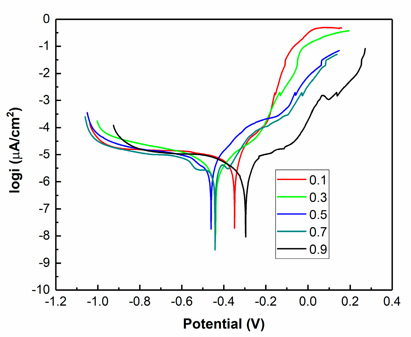
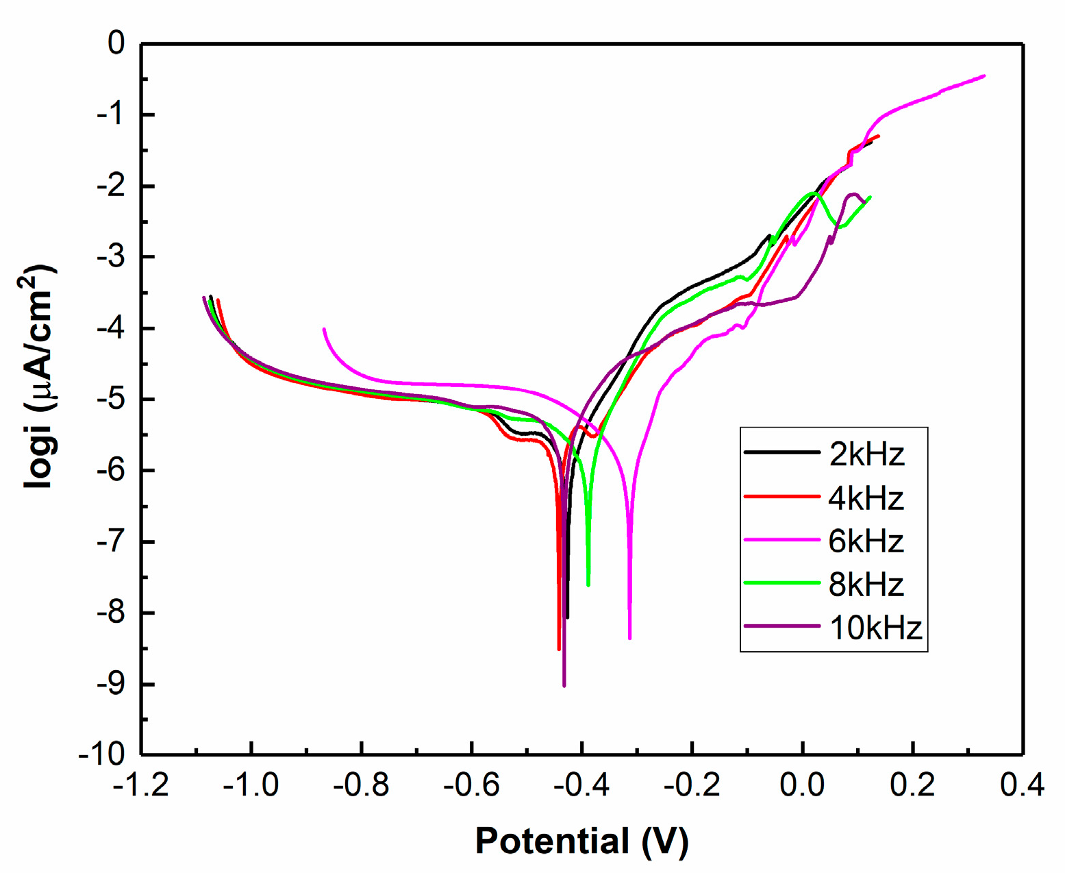
  • Polarization curves of the Ni–Co–BN (h) nanocomposite coatings showed that the pulse parameters had great effects on the corrosion resistance. The change in corrosion current density and polarization resistance indicated that too high or too low pulse parameters were not conducive to the improvement of corrosion resistance of the coatings. The sample with pulse frequency of 4 kHz and duty cycle of 0.7 exhibited good performance in corrosion current density and polarization resistance.

Author Contributions

Conceptualization, H.L. and M.K.; Methodology, H.L., Y.Z., and Y.L.; Validation, Y.Z. and Y.L.; Formal Analysis, H.L.; Investigation, M.J., Y.Z., and Y.L.; Resources, M.K.; Writing-Original Draft Preparation, H.L. and N.S.M.; Writing-Review & Editing, H.L., N.S.M., and M.K.; Visualization, H.L.; Supervision, M.K. and G.Z.; Project Administration, H.L., M.K., G.Z., and C.L.; Funding Acquisition, M.K.

Funding

The work was supposed by the University Natural Science Research Project of Anhui Province (No. KJ2017A438); Research and Innovation Program for Graduate Students in Jiangsu, (No. KYCX17_0646); The technology development programmer for the northern Jiangsu area (No. BN2014019); Innovative Research Team of Anhui Provincial Education Department (No. 2016SCXPTTD); Key Discipline of Material Science and Engineering of Suzhou University (No. 2017XJZDXK3).

Acknowledgments

EDS spectra of Ni–Co–BN (h) nanocomposite coatings surface was analyzed by Research Institute of Nanjing Chemical Industry Group, Sinopec, thanks to senior engineer Jianguo Lu.

Conflicts of Interest

The authors declare no conflict of interest.

References

  1. Jiang, W.; Shen, L.D.; Qiu, M.B. Microhardness, wear, and corrosion resistance of Ni-SiC composite coating with magnetic-field-assisted jet electrodeposition. Mater. Res. Express 2018, 5, 096407. [Google Scholar] [CrossRef]
  2. Dheeraj, P.R.; Patra, A.; Sengupta, S. Synergistic effect of peak current density and nature of surfactant on microstructure, mechanical and electrochemical properties of pulsed electrodeposited Ni-Co-SiC nanocomposites. J. Alloy. Compd. 2017, 729, 1093–1107. [Google Scholar] [CrossRef]
  3. Ratajski, T.; Kalemba-Rec, I.; Indyka, P. Microstructural characterization of SiO2/Ni nanocomposites electrodeposited from a sulphate bath modified by PEI. Mater. Charact. 2018, 142, 478–491. [Google Scholar] [CrossRef]
  4. Alizadeh, M.; Safaei, H. Characterization of Ni-Cu matrix, Al2O3 reinforced nano-composite coatings prepared by electrodeposition. Appl. Surf. Sci. 2018, 456, 195–203. [Google Scholar] [CrossRef]
  5. Li, B.S.; Li, X.; Huan, Y.X. Influence of alumina nanoparticles on microstructure and properties of Ni-B composite coating. J. Alloy. Compd. 2018, 762, 133–142. [Google Scholar] [CrossRef]
  6. Ansari, M.I.; Julka, S.; Thakur, D.G. Enhancement of surface properties with influence of bath pH on electroless Ni-P-ZnO/Al2O3 nano-composite deposits for defence applications. J. Mol. Liq. 2017, 247, 22–33. [Google Scholar] [CrossRef]
  7. Lopes, N.I.A.; Freire, N.H.J.; Resende, P.D. Electrochemical deposition and characterization of ZrO2 ceramic nanocoatings on superelastic NiTi alloy. Appl. Surf. Sci. 2018, 450, 21–30. [Google Scholar] [CrossRef]
  8. Nazir, M.H.; Khan, Z.A.; Saeed, A. Analyzing and Modelling the Corrosion Behavior of Ni/Al2O3, Ni/SiC, Ni/ZrO2 and Ni/Graphene Nanocomposite Coatings. Materials 2017, 10, 1225. [Google Scholar] [CrossRef]
  9. Jiang, Y.C.; Xu, Y.H.; Wang, M. Effects of pulse plating parameters on the microstructure and properties of high frequency pulse electrodeposited Ni-Co-ZrO2 nano-composite coatings. J. Mater. Sci. Mater. Electron. 2017, 28, 610–616. [Google Scholar] [CrossRef]
  10. Adachi, T.; Latthe, S.S.; Gosavi, S.W. Photocatalytic, superhydrophilic, self-cleaning TiO2 coating on cheap, light-weight, flexible polycarbonate substrates. Appl. Surf. Sci. 2018, 458, 917–923. [Google Scholar] [CrossRef]
  11. Wang, Y.X.; Tay, S.L.; Wei, S.H. Microstructure and properties of sol-enhanced Ni-Co-TiO2, nanocomposite coatings on mild steel. J. Alloy. Compd. 2015, 649, 222–228. [Google Scholar] [CrossRef]
  12. Karslioglu, R.; Akbulut, H. Comparison microstructure and sliding wear properties of nickel-cobalt-CNT composite coatings by DC, PC and PRC current electrodeposition. Appl. Surf. Sci. 2015, 353, 615–627. [Google Scholar] [CrossRef]
  13. Liu, Z.; Tabakman, S.; Welsher, K. Carbon Nanotubes in Biology and Medicine: In vitro and in vivo Detection, Imaging and Drug Delivery. Nano Res. 2009, 2, 85–120. [Google Scholar] [CrossRef] [PubMed] [Green Version]
  14. Zhang, L.M.; Xia, J.G.; Zhao, Q.H. Functional Graphene Oxide as a Nanocarrier for Controlled Loading and Targeted Delivery of Mixed Anticancer Drugs. Small 2010, 6, 537–544. [Google Scholar] [CrossRef] [PubMed]
  15. Chen, X.L.; Wu, Z.F.; Xu, S.G. Probing the electron states and metal-insulator transition mechanisms in molybdenum disulphide vertical heterostructures. Nat. Commun. 2015, 6, 6088. [Google Scholar] [CrossRef] [PubMed] [Green Version]
  16. Caldwell, J.D.; Vurgaftman, I.; Tischler, J.G. Atomic-scale photonic hybrids for mid-infrared and terahertz nanophotonics. Nat. Nanotechnol. 2016, 11, 9–15. [Google Scholar] [CrossRef]
  17. Tajaddod, N.; Song, K.; Green, E.C. Exfoliation of Boron Nitride Platelets by Enhanced Interfacial Interaction with Polyethylene. Macromol. Mater. Eng. 2016, 301, 315–327. [Google Scholar] [CrossRef]
  18. Jin, H.L.; Huang, H.H.; He, Y.H. Graphene Quantum Dots Supported by Graphene Nanoribbons with Ultrahigh Electrocatalytic Performance for Oxygen Reduction. J. Am. Chem. Soc. 2015, 137, 7588–7591. [Google Scholar] [CrossRef]
  19. Hu, S.; Lozada-Hidalgo, M.; Wang, F.C. Proton transport through one-atom-thick crystals. Nature 2014, 516, 227–230. [Google Scholar] [CrossRef] [Green Version]
  20. Weng, W.H.; Wang, X.B.; Wang, X. Functionalized hexagonal boron nitride nanomaterials: Emerging properties and applications. Chem. Soc. Rev. 2016, 45, 3989–4012. [Google Scholar] [CrossRef]
  21. Ghazanlou, S.I.; Farhood, A.H.S.; Hosouli, S. Pulse frequency and duty cycle effects on the electrodeposited Ni-Co reinforced with micro and nano-sized ZnO. J. Mater. Sci. Mater. Electron. 2017, 28, 15537–15551. [Google Scholar] [CrossRef]
  22. Yi, D.G.; Shen, L.D.; Zhu, J. Electrochemical corrosion behavior of nano-crytalline nickle prepared by pulsed friction aided jet electrodeposition. Mater. Sci. Technol. 2015, 23, 96–101. (In Chinese) [Google Scholar]
  23. Wang, X.; Shen, L.D.; Qiu, M.B. Effect of Friction on Preparation of NdFeB Nickel Coating by Jet Electrodepostion. J. Electrochem. Sci. 2018, 13, 7706–7717. [Google Scholar] [CrossRef]
  24. Liu, Z.D. Non-Conventional Machining; Peking University Press: Beijing, China, 2017; pp. 221–225. (In Chinese) [Google Scholar]
  25. Bakhit, B. The influence of electrolyte composition on the properties of Ni-Co alloy coatings reinforced by SiC nano-particles. Surf. Coat. Technol. 2015, 275, 324–331. [Google Scholar] [CrossRef]
  26. Bakhit, B.; Akbari, A.; Nasirpouri, F. Corrosion resistance of Ni-Co alloy and Ni-Co/SiC nanocomposite coatings electrodeposited by sediment codeposition technique. Appl. Surf. Sci. 2014, 307, 351–359. [Google Scholar] [CrossRef]
  27. Li, Y.; Jiang, H.; Wand, D. Effects of saccharin and cobalt concentration in electrolytic solution on microhardness of nanocrystalline Ni-Co alloys. Surf. Coat. Technol. 2008, 202, 4952–4956. [Google Scholar] [CrossRef]
  28. Wang, L.; Gao, Y.; Liu, H. Effects of bivalent Co ion on the co-deposition of nickel and nanodiamond particles. Surf. Coat. Technol. 2005, 191, 1–6. [Google Scholar] [CrossRef]
  29. Hou, J. Pulse electroplating and its power supply. Electroplat. Pollut. Control 2011, 31, 4–9. (In Chinese) [Google Scholar]
  30. Xiang, G.P. The Theory and Application of Pulse Plating; Tianjin science and Technology Press: Tianjin, China, 1989; pp. 122–124. (In Chinese) [Google Scholar]
  31. Seifzadeh, D.; Hollagh, A.R. Corrosion Resistance Enhancement of AZ91D Magnesium Alloy by Electroless Ni-Co-P Coating and Ni-Co-P-SiO2 Nanocomposite. J. Mater. Eng. Perform. 2014, 23, 4109–4121. [Google Scholar] [CrossRef]
  32. Wang, Z.C.; Jia, F.; Yu, L. Direct electroless nickel-boron plating on AZ91D magnesium alloy. Surf. Coat. Technol. 2012, 206, 3676–3685. [Google Scholar] [CrossRef]
  33. Zamani, M.; Amadeh, A.; Baghal, S.M.L. Effect of Co content on electrodeposition mechanism and mechanical properties of electrodeposited Ni-Co alloy. Trans. Nonferrous Met. Soc. China 2016, 26, 484–491. [Google Scholar] [CrossRef]
  34. Bakhit, B.; Akbari, A. Effect of particle size and co-deposition technique on hardness and corrosion properties of Ni-Co/SiC composite coatings. Surf. Coat. Technol. 2012, 206, 4964–4975. [Google Scholar] [CrossRef]
Figure 1. Schematic image of pulse jet electrodeposition.
Coatings 09 00050 g001
Figure 2. Surface morphologies of the Ni–Co–BN (h) nanocomposite coatings with pulse frequency of 4 kHz and varying duty cycles: (a) 0.1, (b) 0.3, (c) 0.5, (d) 0.7, (e) 0.9.
Coatings 09 00050 g002
Figure 3. Surface morphologies of the Ni–Co–BN (h) nanocomposite coatings with duty cycle of 0.7 and varying pulse frequencies: (a) 2 kHz, (b) 6 kHz, (c) 8 kHz, (d) 10 kHz.
Coatings 09 00050 g003
Figure 4. Cross-section images of the Ni–Co–BN (h) nanocomposite coatings with pulse frequency of 4 kHz and varying duty cycles: (a) 0.1, (b) 0.3, (c) 0.5, (d) 0.7, (e) 0.9.
Coatings 09 00050 g004
Figure 5. Cross-section images of the Ni–Co–BN (h) nanocomposite coatings with duty cycle of 0.7 and varying pulse frequencies: (a) 2 kHz, (b) 6 kHz, (c) 8 kHz, (d) 10 kHz.
Coatings 09 00050 g005
Figure 6. EDS spectra of Ni–Co–BN (h) nanocomposite coatings surface with duty cycle of 0.7 and pulse frequency of 4 kHz.
Coatings 09 00050 g006
Figure 7. XRD patterns of Ni–Co–BN (h) nanocomposite coatings with varying duty cycles: (a) 0.1, (b) 0.3, (c) 0.5, (d) 0.7, (e) 0.9.
Coatings 09 00050 g007
Figure 8. XRD patterns of Ni–Co–BN (h) nanocomposite coatings with varying pulse frequencies: (a) 2 kHz, (b) 4 kHz, (c) 6 kHz, (d) 8 kHz, (e) 10 kHz.
Coatings 09 00050 g008
Figure 9. Schematic diagram of pulse waveform in ideal and actual conditions: (a) the distortion of the pulse waveform; (b) waveform with extremely small duty cycle; (c) waveform with extremely large duty cycle; (d) waveform with extremely large frequency.
Coatings 09 00050 g009
Figure 10. Polarization curves of Ni–Co–BN (h) nanocomposite coatings with varying duty cycles.
Coatings 09 00050 g010
Figure 11. Polarization curves of Ni–Co–BN (h) nanocomposite coatings with varying pulse frequencies.
Coatings 09 00050 g011
Table 1. Different solution constituents used for this paper.
SolutionComposition
Plating Solution/(g L−1)200.0 NiSO4·6H2O + 5.0 CoSO4·7H2O + 50.0 NiCl2·6H2O + 30.0 H3BO3 + 0.05 Sodium dodecyl sulfate + 0.002 Thiourea + 5.0 BN (h) nanoparticles
Electric Cleaning Solution/(g L−1)25.0 NaOH + 21.7 Na2CO3 + 50.0 Na3PO4 + 2.4 NaCl
Strong Activation Solution/(g L−1)25.0 Hydrochloric acid + 140.1 NaCl
Weak Activation Solution/(g L−1)141.2 Na3C6H5O7·2H2O + 94.2 H3C6H5O7·H2O + 3.0 NiCl2·6H2O
Table 2. Partial data of Ni–Co–BN (h) nanocomposite coatings with varying pulse parameters.
Pulse ParametersCo (wt %)N (wt %)Ni
(wt %)
Grain Size (nm)Sa (µm)Microhardness
(HV0.05)
Frequency (kHz)Duty Cycle
40.112.601.5885.8220.31.466411.7
40.313.711.7284.5721.61.305447.8
40.519.903.0478.3825.30.832640.7
40.727.343.8268.8427.20.664719.2
40.921.682.8975.4328.40.936631.3
20.724.773.4871.7528.10.870685.2
60.722.873.3373.8028.90.764673.6
80.719.933.1676.9130.40.890655.4
100.717.622.9779.4131.60.995641.6
Table 3. Electrochemical parameters of different samples.
Pulse ParametersEocp
(mV)
βa
(mV/dec)
βc
(mV/dec)
Icorr
(µA/cm2)
Ecorr
(mV)
Rp
(kΩ cm2)
Frequency (kHz)Duty Cycle
40.1−435138.69361.465.90−3897.37
40.3−425111.80195.032.81−47610.97
40.5−431136.69215.852.62−43313.87
40.7−46277.59174.350.77−42230.11
40.9−327361.82200.093.57−36515.69
20.7−47577.35261.351.62−42515.97
60.7−26972.95176.261.76−31312.74
80.7−47770.48411.132.76−3809.44
100.7−487129.67520.754.74−4389.52

