Comparison of the Optical and Electrical Properties of Al-Doped ZnO Films Using a Lorentz Model


Abstract
1. Introduction
2. Materials and Methods
2.1. Sample Preparation
2.2. Optical Models
3. Results and Discussion
3.1. Deposition of Intrinsic ZnO Film
3.2. Deposition of AZO Films
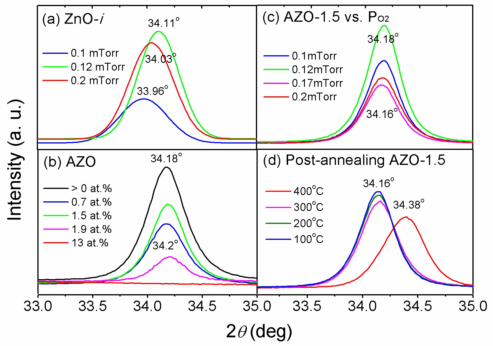
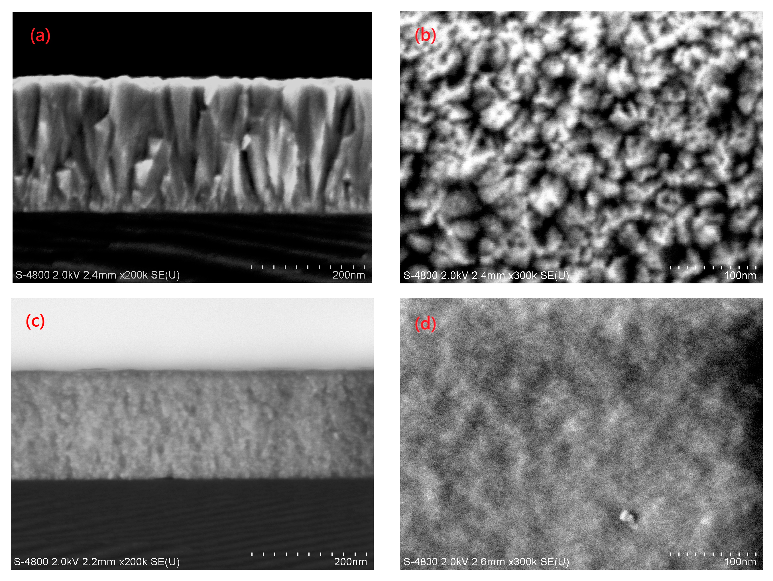
3.3. Structural Properties of the AZO Film
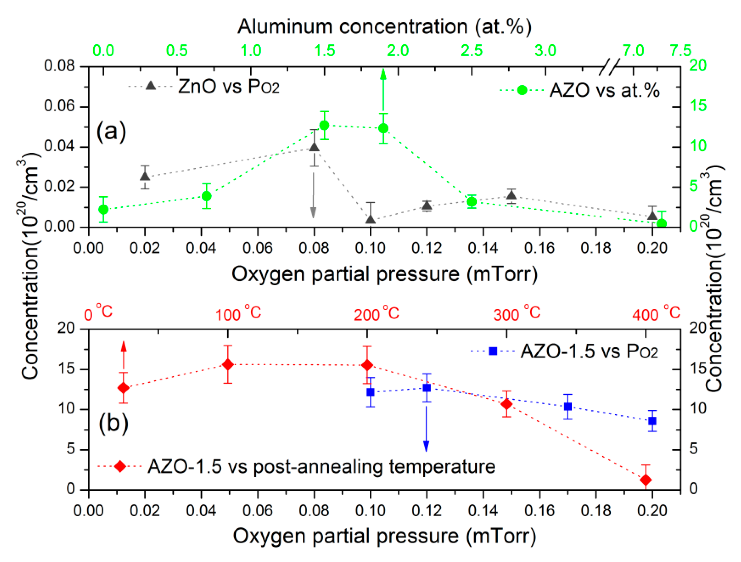
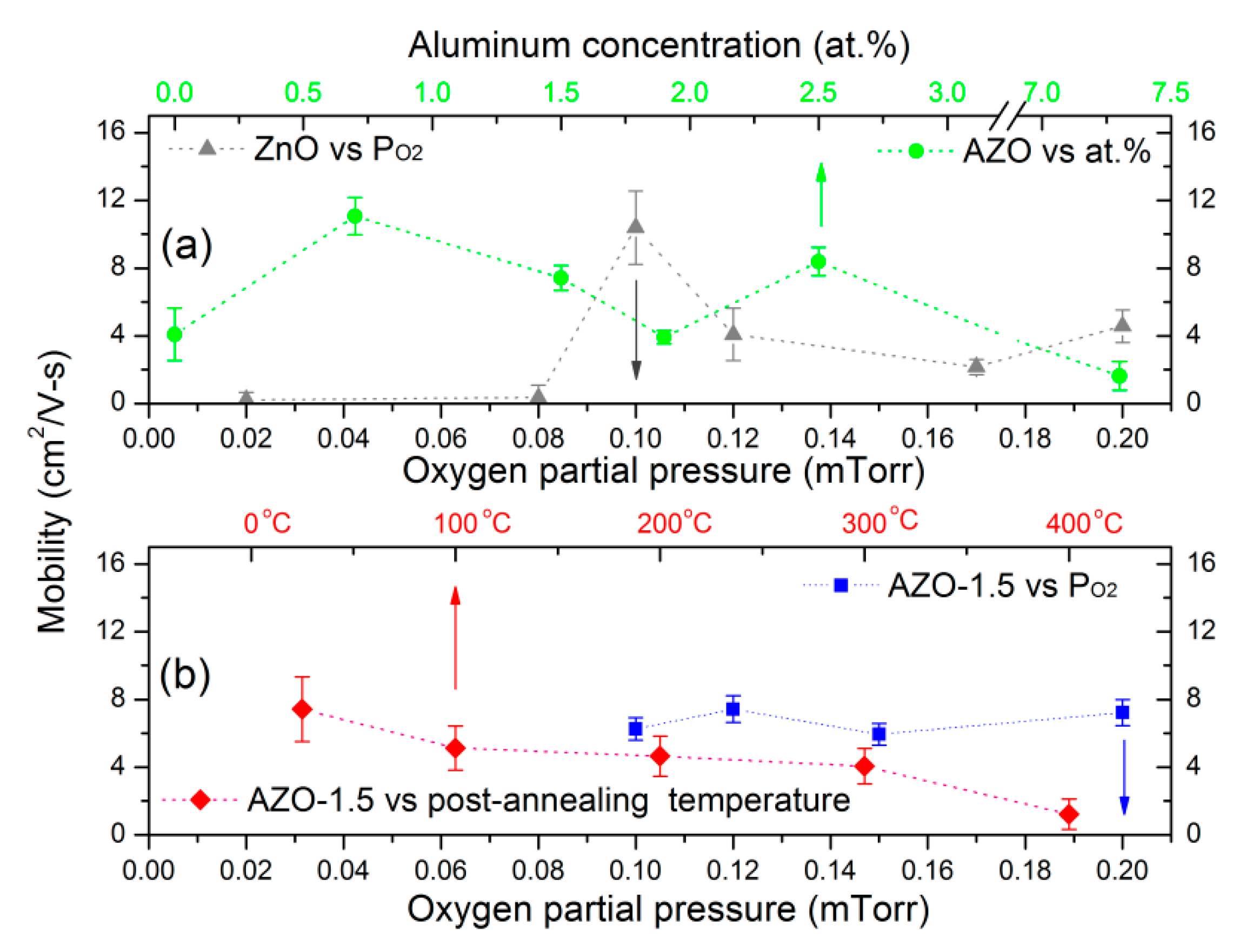
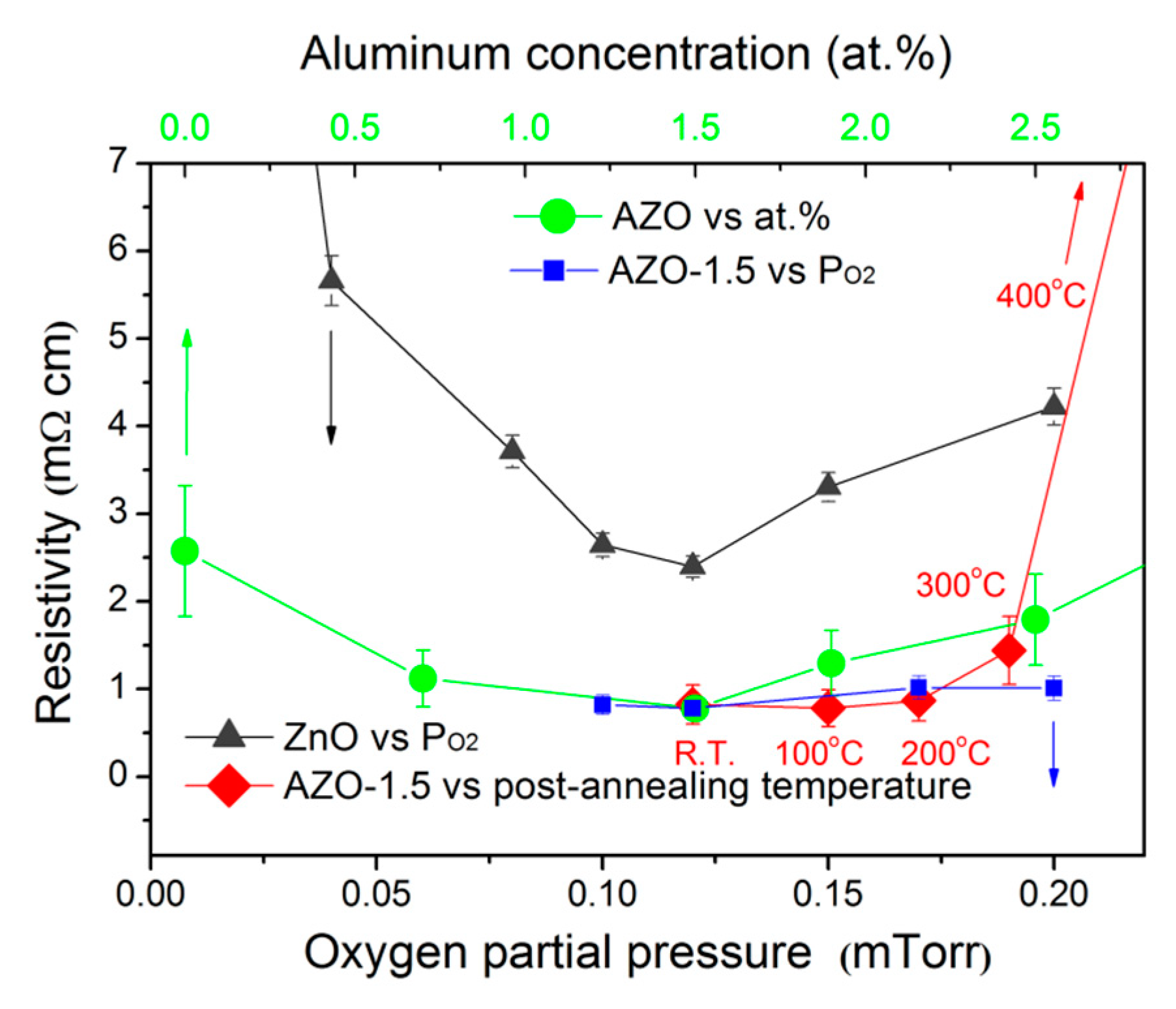
3.4. Electrical Properties
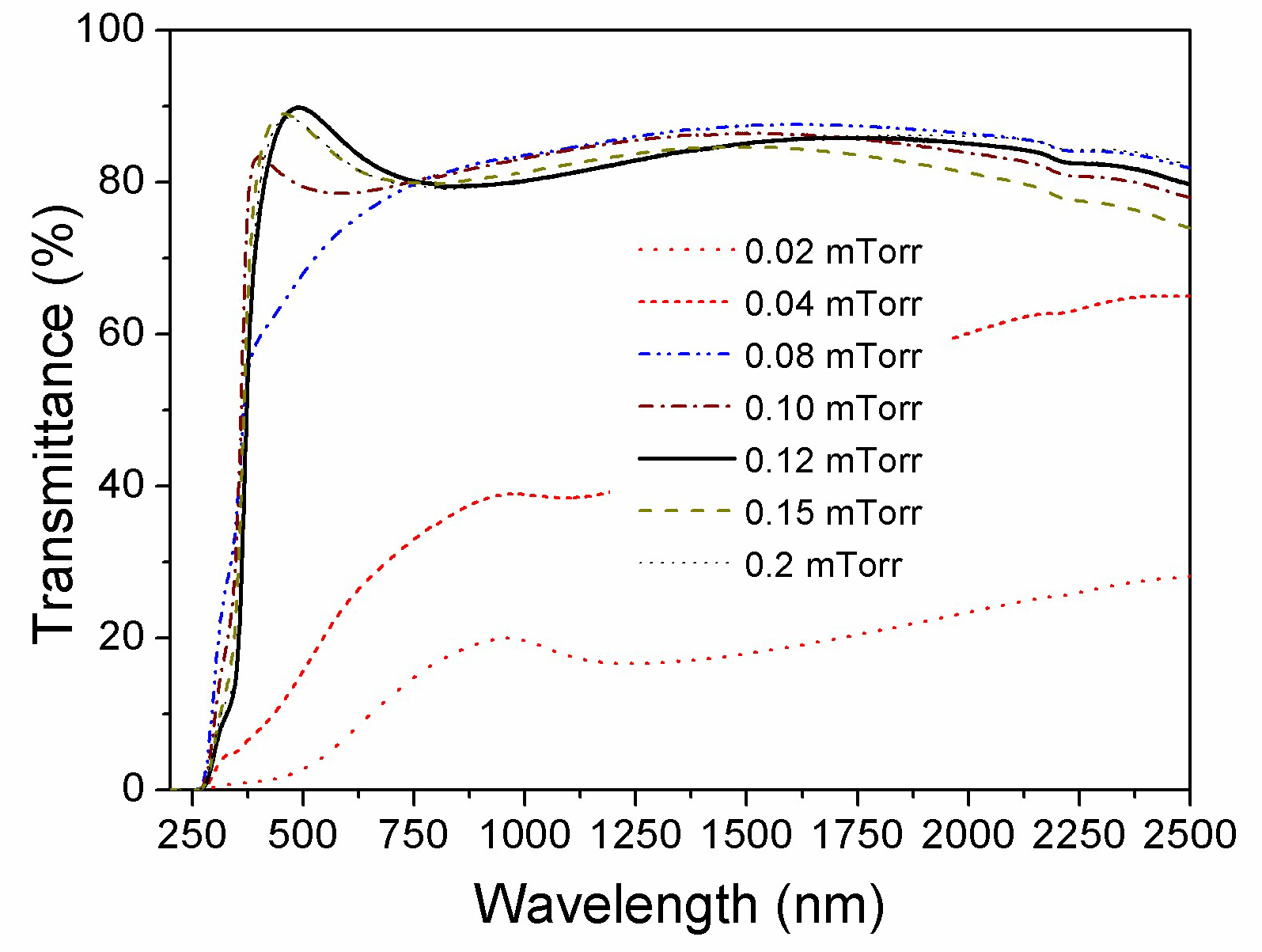
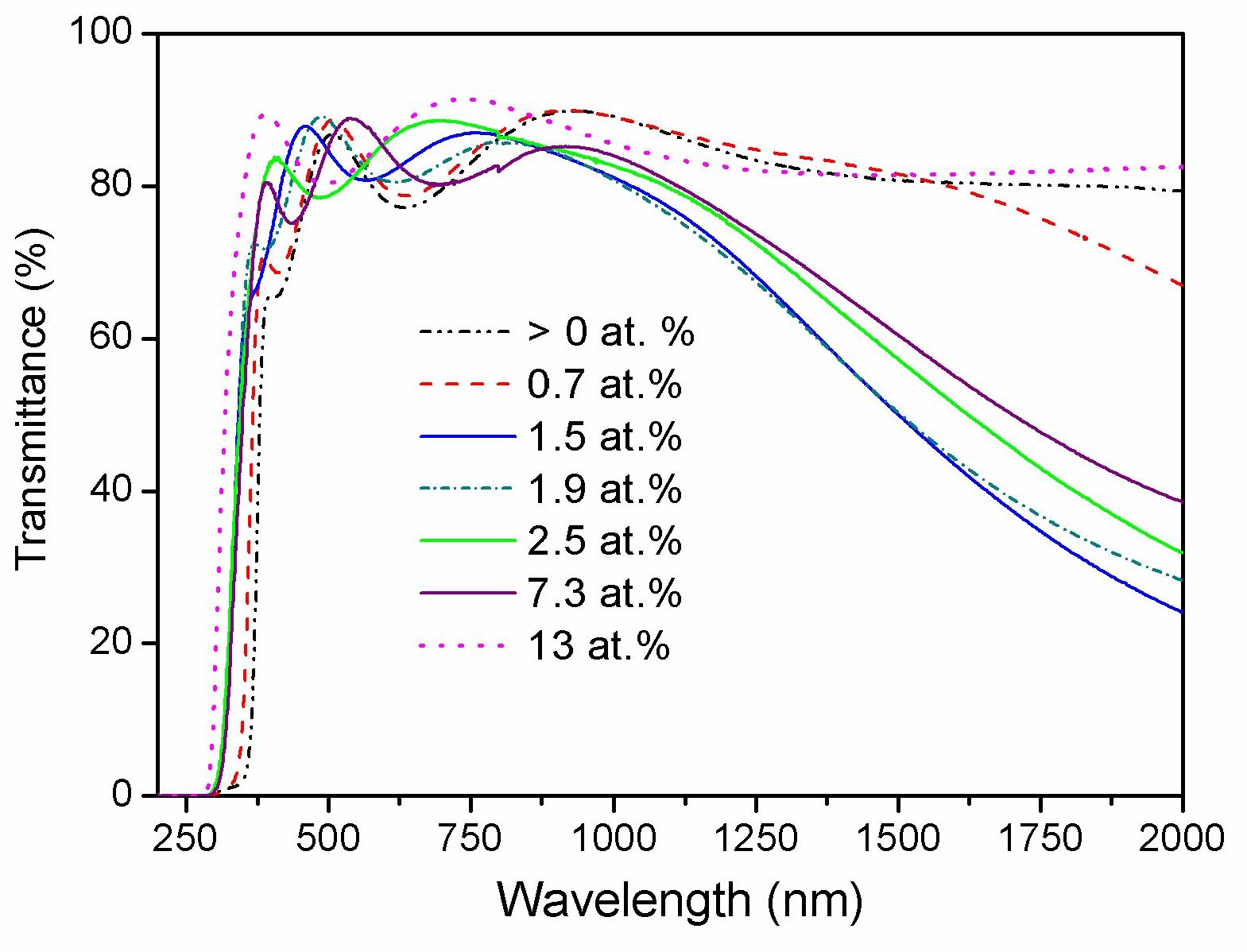
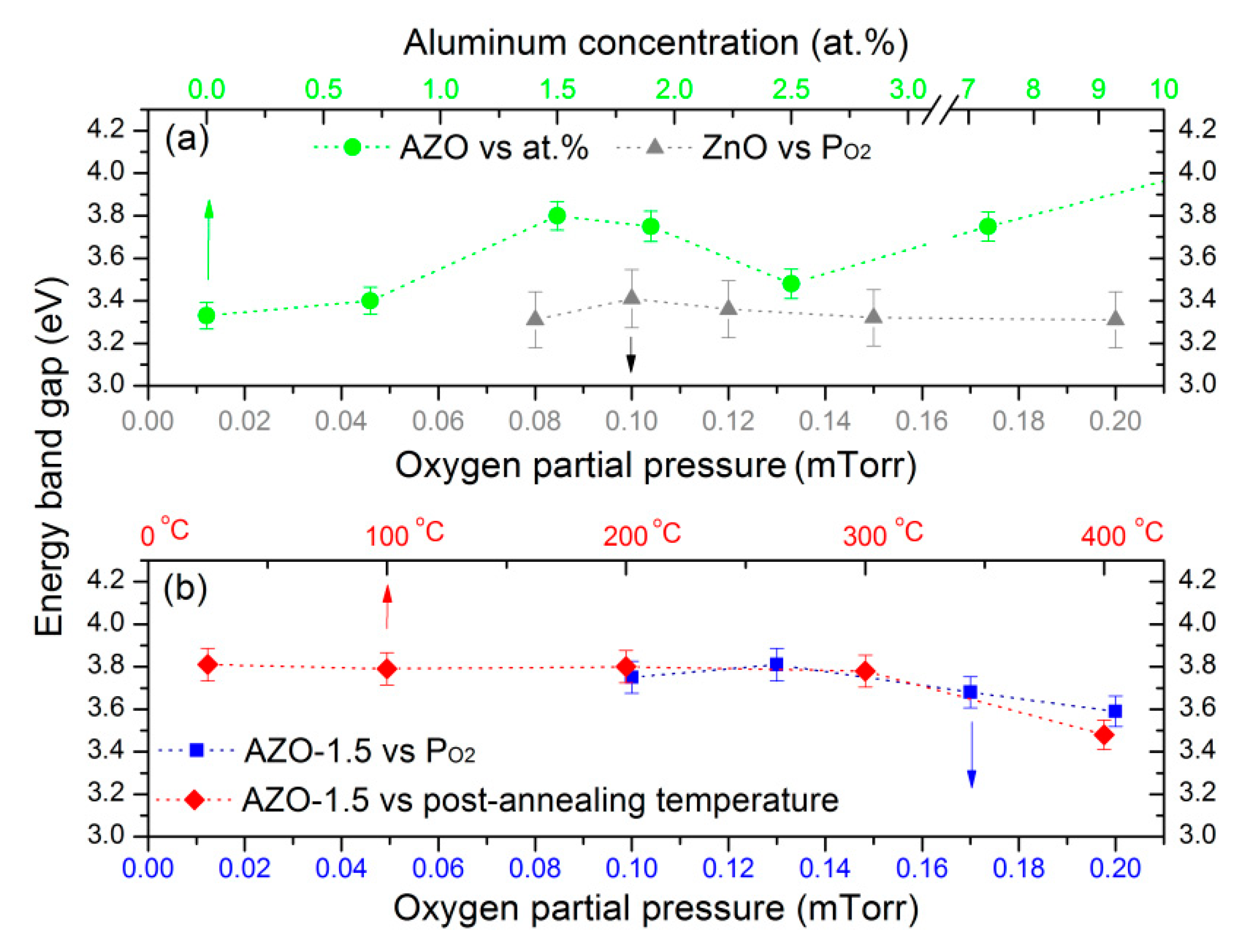
3.5. Optical Properties
3.6. Spectroscopic Ellipsometry Study
4. Conclusions
Author Contributions
Funding
Conflicts of Interest
References
- Jiang, X.; Jia, C.L.; Szyszka, B. Manufacture of specific structure of aluminum-doped zinc oxide films by patterning the substrate surface. Appl. Phys. Lett. 2002, 80, 3090. [Google Scholar] [CrossRef]
- Kohan, A.F.; Ceder, G.; Morgan, D.; Van De Walle, C.G. First-principles study of native point defects in ZnO. Phys. Rev. B 2000, 61, 15019. [Google Scholar] [CrossRef]
- Kayaci, F.; Vempati, S.; Donmez, I.; Biyikli, N.; Uyar, T. Role of zinc interstitials and oxygen vacancies of ZnO in photocatalysis: A bottom-up approach to control defect density. Nanoscale 2014, 6, 10224–10234. [Google Scholar] [CrossRef] [PubMed]
- Takata, S.; Minami, T.; Nanto, H. The stability of aluminium-doped ZnO transparent electrodes fabricated by sputtering. Thin Solid Films 1986, 135, 183–187. [Google Scholar] [CrossRef]
- Minami, T. New n-type transparent conducting oxides. MRS Bull. 2000, 25, 38–44. [Google Scholar] [CrossRef]
- T-Thienprasert, J.; Rujirawat, S.; Klysubun, W.; Duenow, J.N.; Coutts, T.J.; Zhang, S.B.; Look, D.C.; Limpijumnong, S. Compensation in Al-doped ZnO by Al-related acceptor complexes: Synchrotron X-ray absorption spectroscopy and theory. Phys. Rev. Lett. 2013, 110, 055502. [Google Scholar] [CrossRef]
- Verma, A.; Khan, F.; Kumar, D.; Kar, M.; Chakravarty, B.C.; Singh, S.N.; Husain, M. Sol-gel derived aluminum doped zinc oxide for application as anti-reflection coating in terrestrial silicon solar cells. Thin Solid Films 2010, 518, 2649–2653. [Google Scholar] [CrossRef]
- Budianu, E.; Purica, M.; Iacomi, F.; Baban, C.; Prepelita, P.; Manea, E. Silicon metal-semiconductor-metal photodetector with zinc oxide transparent conducting electrodes. Thin Solid Films 2008, 516, 1629–1633. [Google Scholar] [CrossRef]
- Chiang, Y.-F.; Sung, C.-C.; Ro, R. Effects of metal buffer layer on characteristics of surface acoustic waves in ZnO/metal/diamond structures. Appl. Phys. Lett. 2010, 96, 154104. [Google Scholar] [CrossRef]
- Jeong, S.S.; Mittiga, A.; Salza, E.; Masci, A.; Passerini, S. Electrodeposited ZnO/Cu2O heterojunction solar cells. Electrochim. Acta 2008, 53, 2226–2231. [Google Scholar] [CrossRef]
- Yu, K.M.; Mayer, M.A.; Speaks, D.T.; He, H.; Zhao, R.; Hsu, L.; Mao, S.S.; Haller, E.E.; Walukiewicz, W. Ideal transparent conductors for full spectrum photovoltaics. J. Appl. Phys. 2012, 111, 123505. [Google Scholar] [CrossRef]
- Volintiru, I.; Creatore, M.; Van De Sanden, M.C.M. In situ spectroscopic ellipsometry growth studies on the Al-doped ZnO films deposited by remote plasma-enhanced metalorganic chemical vapor deposition. J. Appl. Phys. 2008, 103, 033704. [Google Scholar] [CrossRef]
- Lin, K.M.; Lee, Y.H.; Huang, W.Y.; Hsieh, C.T.; Hsu, C.K. Spectroscopic ellipsometry study on strain evolution of transparent conductive thin films prepared by RF sputtering method. Adv. Mater. Res. 2015, 1110, 222–225. [Google Scholar] [CrossRef]
- Kinsey, N.; Devault, C.; Kim, J.; Ferrera, M.; Shalaev, V.M.; Boltasseva, A. Epsilon-near-zero Al-doped ZnO for ultrafast switching at telecom wavelengths. Optica 2015, 2, 616–622. [Google Scholar] [CrossRef]
- Hsu, J.-C.; Chiang, Y.-S. Influence of oxygen on zinc oxide films fabricated by ion-beam sputter deposition. ISRN Mater. Sci. 2013, 2013, 710798. [Google Scholar] [CrossRef]
- Chen, Y.-Y.; Hsu, J.-C.; Wang, P.W.; Pai, Y.-W.; Wu, C.-Y.; Lin, Y.-H. Dependence of resistivity on structure and composition of AZO films fabricated by ion beam co-sputtering deposition. Appl. Surf. Sci. 2011, 257, 3446–3450. [Google Scholar] [CrossRef]
- Chen, Y.-Y.; Hsu, J.-C.; Lee, C.-Y.; Wang, P.W. Influence of oxygen partial pressure on structural, electrical, and optical properties of Al-doped ZnO film prepared by the ion beam co-sputtering method. J. Mater. Sci. 2013, 48, 1225–1230. [Google Scholar] [CrossRef]
- Hsu, J.-C.; Lin, Y.-H.; Wang, P.W.; Chen, Y.-Y. Spectroscopic ellipsometry studies on various zinc oxide films deposited by ion beam sputtering at room temperature. Appl. Opt. 2012, 51, 1209–1215. [Google Scholar] [CrossRef]
- Chen, Y.-Y.; Wang, P.W.; Hsu, J.-C.; Lee, C.-Y. Post-annealing properties of aluminum-doped zinc oxide films fabricated by ion beam co-sputtering. Vacuum 2013, 87, 227–231. [Google Scholar] [CrossRef]
- Woollam, J.A.; Bungay, C.L.; Tiwald, T.E.; Liphardt, M.M.; Synowicki, R.A.; Pribil, G.K.; Herzinger, C.M.; Johs, B.D.; Hilfiker, J.N. Sample Analysis Methodology Utilizing Electromagnetic Radiation. U.S. Patent No. 7,385,697, 10 June 2008. [Google Scholar]
- Gong, L.; Ye, Z.; Lu, J.; Zhu, L.; Huang, J.; Gu, X.; Zhao, B. Highly transparent conductive and near-infrared reflective ZnO:Al thin films. Vacuum 2010, 84, 947–952. [Google Scholar] [CrossRef]
- Kim, H.; Gilmore, C.M.; Pique, A.; Horwitz, J.S.; Mattoussi, H.; Murata, H.; Kafafi, Z.H.; Chrisey, D.B. Electrical, optical, and structural properties of indium–tin–oxide thin films for organic light-emitting devices. J. Appl. Phys. 1999, 86, 6451. [Google Scholar] [CrossRef]
- Aspnes, D.E.; Theeten, J.B.; Hottier, F. Investigation of effective-medium models of microscopic surface roughness by spectroscopic ellipsometry. Phys. Rev. B 1979, 20, 3292. [Google Scholar] [CrossRef]
- Fujiwara, H. Spectroscopic Ellipsometry: Principles and Applications; John Wiley & Sons: Hoboken, NJ, USA, 2007. [Google Scholar]
- Tseng, K.-S.; Lo, Y.-L. Investigation into inhomogeneous electrical and optical properties of indium tin oxide film using spectroscopic ellipsometry with multi-layer optical models. Opt. Mater. Express 2014, 4, 43–56. [Google Scholar] [CrossRef]
- D’Elia, S.; Scaramuzza, N.; Ciuchi, F.; Versace, C.; Strangi, G.; Bartolino, R. Ellipsometry investigation of the effects of annealing temperature on the optical properties of indium tin oxide thin films studied by Drude–Lorentz model. Appl. Surf. Sci. 2009, 255, 7203–7211. [Google Scholar] [CrossRef]
- Hamberg, I.; Granqvist, C.G. Evaporated Sn-doped In2O3 films: Basic optical properties and applications to energy-efficient windows. J. Appl. Phys. 1986, 60, R123. [Google Scholar] [CrossRef]
- Steinhauser, J.; Faÿ, S.; Oliveira, N.; Vallat-Sauvain, E.; Ballif, C. Transition between grain boundary and intragrain scattering transport mechanisms in boron-doped zinc oxide thin films. Appl. Phys. Lett. 2007, 90, 142107. [Google Scholar] [CrossRef]
- Tahar, R.B.H.; Ban, T.; Ohya, Y.; Takahashi, Y. Tin doped indium oxide thin films: Electrical properties. J. Appl. Phys. 1998, 83, 2631. [Google Scholar] [CrossRef]
- Hsu, J.-C.; Lee, C.-C. Single- and dual-ion-beam sputter deposition of titanium oxide films. Appl. Opt. 1998, 37, 1171–1176. [Google Scholar] [CrossRef]
- Jiang, Y.; Bahlawane, N. Effect of nucleation and growth kinetics on the electrical and optical properties of undoped ZnO films. J. Phys. Chem. C 2010, 114, 5121–5125. [Google Scholar] [CrossRef]
- Minami, T.; Hanato, H.; Shooji, S.; Takata, S. The stability of zinc oxide transparent electrodes fabricated by RF magnetron sputtering. Thin Solid Films 1984, 111, 167–174. [Google Scholar] [CrossRef]
- Haug, F.-J.; Geller, Z.; Zogg, H.; Tiwari, A.N.; Vignali, C. Influence of deposition conditions on the thermal stability of ZnO:Al films grown by RF magnetron sputtering. J. Vac. Sci. Technol. A 2001, 19, 171. [Google Scholar] [CrossRef]
- Kim, K.-K.; Tampo, H.; Song, J.-O.; Seong, T.-Y.; Park, S.-J.; Lee, J.-M.; Kim, S.-W.; Fujita, S.; Niki, S. Effect of rapid thermal annealing on Al doped n-ZnO films grown by RF-magnetron sputtering. Jpn. J. Appl. Phys. 2005, 44, 4776–4779. [Google Scholar] [CrossRef]
- Kittel, C. Introduction to Solid State Physics, 5th ed.; Wiley: Hoboken, NJ, USA, 1976. [Google Scholar]
- Guglielmi, M.; Menegazzo, E.; Paolizzi, M.; Gasparro, G.; Ganz, D.; Pütz, J.; Aegerter, M.A.; Hubert-Pfalzgraf, L.; Pascual, C.; Durán, A.; et al. Sol-gel deposited Sb-doped tin oxide films. J. Sol-Gel Sci. Technol. 1998, 13, 679–683. [Google Scholar] [CrossRef]
- Kuprenaite, S.; Abrutis, A.; Kubilius, V.; Murauskas, T.; Saltyte, Z.; Plausinaitiene, V. Effects of annealing conditions and film thickness on electrical and optical properties of epitaxial Al-doped ZnO films. Thin Solid Films 2016, 599, 19–26. [Google Scholar] [CrossRef]
- Singh, A.V.; Mehra, R.M.; Buthrath, N.; Wakahara, A.; Yoshida, A. Highly conductive and transparent aluminum-doped zinc oxide thin films prepared by pulsed laser deposition in oxygen ambient. J. Appl. Phys. 2001, 90, 5661. [Google Scholar] [CrossRef]
- Lu, J.; Ye, Z.; Zeng, Y.; Zhu, L.; Wang, L.; Yuan, J.; Zhao, B.; Liang, Q. Structural, optical, and electrical properties of (Zn,Al)O films over a wide range of compositions. J. Appl. Phys. 2006, 100, 073714. [Google Scholar] [CrossRef]
- Tan, S.T.; Chen, B.J.; Sun, X.W.; Fan, W.J.; Kwok, H.S.; Zhang, X.H.; Chua, S.J. Blueshift of optical band gap in ZnO thin films grown by metal-organic chemical-vapor deposition. J. Appl. Phys. 2005, 98, 013505. [Google Scholar] [CrossRef]
- Sernelins, B.E.; Berggren, K.-F.; Jin, Z.-C.; Hamberg, I.; Granqvist, C.G. Band-gap tailoring of ZnO by means of heavy Al doping. Phys. Rev. B 1988, 37, 10244. [Google Scholar] [CrossRef]
- Tauc, J.; Grigorovici, R.; Vancu, A. Optical properties and electronic structure of amorphous germanium. Phys. Status Solidi B 1966, 15, 627–637. [Google Scholar] [CrossRef]
- Chinta, P.V.; Lozano, O.; Wadekar, P.V.; Hsieh, W.C.; Seo, H.W.; Yeh, S.W.; Liao, C.H.; Tu, L.W.; Ho, N.J.; Zhang, Y.S.; et al. Evolution of metallic conductivity in epitaxial ZnO thin films on systematic Al doping. J. Electron. Mater. 2017, 46, 2030–2039. [Google Scholar] [CrossRef]
- Yamada, T.; Makino, H.; Yamamoto, N.; Yamamoto, T. Ingrain and grain boundary scattering effects on electron mobility of transparent conducting polycrystalline Ga-doped ZnO films. J. Appl. Phys. 2010, 107, 123534. [Google Scholar] [CrossRef]
- Nomoto, J.; Makino, H.; Yamamoto, T. Carrier mobility of highly transparent conductive Al-doped ZnO polycrystalline films deposited by radio-frequency, direct-current, and radio-frequency-superimposed direct-current magnetron sputtering: Grain boundary effect and scattering in the grain bulk. J Appl. Phys. 2015, 117, 045304. [Google Scholar] [CrossRef]
- Knoops, H.C.M.; Van De Loo, B.W.H.; Smit, S.; Ponomarev, M.V.; Weber, J.-W.; Sharma, K.; Kessels, W.M.M.; Creatore, M. Optical modeling of plasma-deposited ZnO films: Electron scattering at different length scales. J. Vac. Sci. Technol. A 2015, 33, 021509. [Google Scholar] [CrossRef]
- Pei, Z.; Zhang, X.; Zhang, G.; Gong, J.; Sun, C.; Huang, R.; Wen, L. Transparent conductive ZnO:Al thin films deposited on flexible substrates prepared by direct current magnetron sputtering. Thin Solid Films 2006, 497, 20–23. [Google Scholar] [CrossRef]
- Lee, C.-C.; Hsu, J.-C.; Wong, D.-H. The characteristics of some metallic oxides prepared in high vacuum by ion beam sputtering. Appl. Surf. Sci. 2001, 171, 151–156. [Google Scholar] [CrossRef]
- Macleod, H.A. Thin-Film Optical Filter, 4th ed.; CRC Press: Boca Raton, FL, USA, 2010. [Google Scholar]


| Sample | H * (mm) | Al Dopant (at.%) | Thickness (nm) | Surface Roughness (nm) |
|---|---|---|---|---|
| AZO-0 | 13.5 ± 3.1 | 0 + 0.1 | 238 ± 11 | 2.68 ± 0.21 |
| AZO-0.7 | 22.0 ± 2.9 | 0.69 ± 0.1 | 218 ± 10 | 2.54 ± 0.18 |
| AZO-1.5 | 28.5 ± 2.5 | 1.5 ± 0.1 | 221 ± 9 | 2.48 ± 0.15 |
| AZO-1.9 | 35.0 ± 2.5 | 1.9 ± 0.2 | 245 ± 11 | 1.73 ± 0.14 |
| AZO-2.5 | 38.0 ± 2.3 | 2.5 ± 0.2 | 220 ± 15 | 1.70 ± 0.15 |
| AZO-7.3 | 48.0 ± 3.1 | 7.3 ± 0.2 | 231 ± 14 | 1.12 ± 0.16 |
| AZO-13 | 50.0 ± 3.5 | 13.0 ± 0.2 | 216 ± 11 | 1.02 ± 0.15 |
| AZO (at.%) | ε∞ | AL (eV)2 | BL (eV) | EL (eV) | AD (eV)2 | BD (eV) |
|---|---|---|---|---|---|---|
| 0 | 3.42 | 5.41 | 0.203 | 3.88 | 0.52 | 0.400 |
| 0.7 | 3.30 | 5.84 | 0.185 | 3.87 | 0.78 | 0.149 |
| 1.5 | 2.96 | 10.3 | 0.236 | 4.27 | 1.56 | 0.107 |
| 1.9 | 2.97 | 10.9 | 0.191 | 4.49 | 1.90 | 0.133 |
| 2.5 | 2.8 | 11.6 | 0.210 | 4.18 | 1.33 | 0.110 |
| 7.3 | 2.84 | 9.86 | 0.330 | 4.41 | 0.59 | 0.460 |
| 13 | 3.11 | 2.57 | 0.001 | 4.12 | 0.21 | 0.002 |
© 2018 by the authors. Licensee MDPI, Basel, Switzerland. This article is an open access article distributed under the terms and conditions of the Creative Commons Attribution (CC BY) license (http://creativecommons.org/licenses/by/4.0/).
Share and Cite
Hsu, J.-C.; Chen, Y.-Y. Comparison of the Optical and Electrical Properties of Al-Doped ZnO Films Using a Lorentz Model. Coatings 2019, 9, 4. https://doi.org/10.3390/coatings9010004
Hsu J-C, Chen Y-Y. Comparison of the Optical and Electrical Properties of Al-Doped ZnO Films Using a Lorentz Model. Coatings. 2019; 9(1):4. https://doi.org/10.3390/coatings9010004
Chicago/Turabian StyleHsu, Jin-Cherng, and Yu-Yun Chen. 2019. "Comparison of the Optical and Electrical Properties of Al-Doped ZnO Films Using a Lorentz Model" Coatings 9, no. 1: 4. https://doi.org/10.3390/coatings9010004
APA StyleHsu, J.-C., & Chen, Y.-Y. (2019). Comparison of the Optical and Electrical Properties of Al-Doped ZnO Films Using a Lorentz Model. Coatings, 9(1), 4. https://doi.org/10.3390/coatings9010004