Article

One-Step Fabrication and Localized Electrochemical Characterization of Continuous Al-Alloyed Intermetallic Surface Layer on Magnesium Alloy

1
State Key Laboratory of Metal Matrix Composites, Shanghai Jiao Tong University, Shanghai 200240, China
2
Key Laboratory of Advanced Ceramics and Machining Technology (Ministry of Education), School of Materials Science and Engineering, Tianjin University, Tianjin 300072, China
3
Tianjin Key Laboratory of Composite and Functional Materials, School of Materials Science and Engineering, Tianjin University, Tianjin 300072, China
*
Author to whom correspondence should be addressed.
These authors contributed equally to this work.
Coatings 2018, 8(4), 148; https://doi.org/10.3390/coatings8040148
Submission received: 2 March 2018 / Revised: 7 April 2018 / Accepted: 8 April 2018 / Published: 18 April 2018

Abstract

:
A continuous intermetallic compound coating was fabricated on AZ91D magnesium alloy via heat treatment at 400 °C in AlCl3-NaCl molten salts for 10 h. The microstructure and composition of the coating were characterized by scanning electron microscope and energy dispersive X-ray spectrometry. The results showed that the coating has a two-layer structure (the outer Mg2Al3 phase layer and the inner Mg17Al12 phase layer) up to 37 μm thick with compact and planar interfaces between the layers and the substrate. The corrosion property of the coating was investigated using electrochemical impedance spectroscopy (EIS) and two localized electrochemical techniques, i.e., localized electrochemical impedance spectroscopy (LEIS) and scanning vibrating electrode technique (SVET). The charge transfer resistance (Rct) of the Al-alloyed coating was 2119 Ω cm2. The localized impedance and current density maps obtained through LEIS and SVET indicate not only significantly improved corrosion resistance (the impedance modulus increased by one order of magnitude and the current density decreased to approximately 3.8%, compared with the substrate) but also defect-free surface condition.

Graphical Abstract

1. Introduction

Magnesium (Mg) and its alloys are of excellent mechanical and physical properties including high specific strength and stiffness, good castability and good electromagnetic shielding properties. Therefore, they are expected to have widespread applications such as automobile, aerospace, biomedicine and electronics industries [1,2,3,4]. However, the limited corrosion resistance has hampered their further applications [5,6,7,8,9,10]. Aluminizing of Mg alloys is a promising approach to enhance the corrosion resistance, owing to the formation of diffusion coatings comprised of intermetallic phases such as γ-Mg17Al12 and β-Mg2Al3 [11,12,13]. Such diffusion coatings exhibit high adhesion strength due to the presence of the metallurgical diffusion bond [14,15], whilst most of the advantages of Mg alloys such as electromagnetic shielding properties will not be sacrificed.
Large numbers of strategies have been developed to prepare Mg–Al alloyed diffusion coatings, which can be divided into two categories: one-step processes and multi-step processes. One-step processes include packed powder cementation [14,16,17,18,19,20,21,22,23], chemical vapor deposition (CVD) [24,25], vacuum aluminizing [26,27,28,29], laser cladding [30,31,32], etc. Among them, packed powder cementation has been widely used due to its simplicity, low equipment requirement and good applicability for complex-shaped components. For the first time, Shigematsu et al. [20] obtained a 750 μm thick coating mainly consists of γ-Mg17Al12 on AZ91D Mg alloys by the heat treatment at 450 °C for one hour in aluminum (Al) powder. Liu et al. [26] achieved similar results while replacing the protective argon gas with a vacuum condition. Mola [19] prepared Al- and Al/Zn-enriched alloyed coating on Mg with a thickness up to 900 μm. The diffusion process was carried out at 445 °C for one hour via embedding in Al + Zn powder mixture under certain pressure. Christoglou et al. [24] fabricated aluminized coatings on Mg via a technique known as pack bed chemical vapor deposition (PBCVD). Chen et al. [25] improved this process by applying mechanical vibration simultaneously. As a result, the coatings are denser and of more homogenously distributed intermetallic phases. However, previously reported one-step processes have failed to produce continuous intermetallic compound coatings to cover the substrate, where eutectic intermetallic phases (e.g., γ-Mg17Al12) are randomly distributed in α-Mg phase. As a result, the improvement of the corrosion resistance was limited.
Multi-step processes, which overcome the aforementioned limitation by separating the diffusion step from the coating step, have been demonstrated to successfully fabricate continuous intermetallic compound coatings on Mg alloys [33,34,35,36,37,38,39]. Most of the previous works have been carried out by prefabricating a continuous Al layer on the Mg substrate. Subsequently, the heat treatment was conducted at relatively lower temperature than the eutectic point. During this step, Al diffuses into the substrate, forming continuous intermetallic phases. For example, Spencer and Zhang [34] applied a layer of Al on AZ91 Mg alloys through cold spray. After annealing at 400 °C for 20 h, 150–200 μm thick continuous intermetallic coatings were generated with a double-layered structure of outer Mg2Al3 and inner Mg17Al12, increasing corrosion resistance to the level of Al. Yang et al. [35] achieved similar results on AZ91D Mg alloys via electrodeposition of Al and subsequent solution treatment at 420 °C for two hours and aging at 200 °C for 12 h. Recently, Ishibashi et al. [37] obtained continuous Mg–Al coatings on AZ91 Mg alloys by heat treatment at 280 °C for three hours in argon (Ar) atmosphere after magnetron sputtering of Al. Compared to one-step processes, however, aforementioned multi-step processes are more complicated in that a further grinding process is required to remove the top Al(Mg) solid solution layer and thus obtain continuous intermetallic compound surface. Moreover, the prefabrication of the Al layer requires additional equipment and also complicates the preparation process.
In the present work, a novel one-step process was proposed to prepare continuous Mg–Al intermetallic compound coatings on Mg alloys, which is achieved by the heat treatment of Mg alloy in AlCl3-NaCl molten salts. It is interesting to note that this process is compatible to the conventional powder cementation process. Due to the low melting temperature of AlCl3-NaCl mixture, the aluminizing process can be carried out at relatively low temperature. Combined with scanning electron microscope (SEM) and energy dispersive X-ray spectrometry (EDS), the microstructure and phase structure of the diffusion coating were characterized. In particular, localized electrochemical techniques including localized electrochemical impedance spectroscopy (LEIS) and scanning vibrating electrode technique (SVET) were used to characterize the corrosion resistance of the aluminized Mg alloys. Compared to conventional electrochemical analysis techniques, LEIS and SVET provide specific information (e.g., defects, homogeneity and integrity) about corrosion properties within selected area on the surface. As a result, the defect in the heterogeneous electrode can be easily detected, while conventional electrochemical analysis techniques give macroscopic information and provide little indication of its presence [40].

2. Materials and Methods

A die-cast AZ91D Mg alloy (8.71 wt.% Al, 0.73 wt.% Zn, 0.17 wt.% Mn, other elements less than 0.01 wt.%, and balanced Mg) was employed as the substrate. The as-received alloy sheet was cut into specific size through wire cutting. These specimens were then ground and polished using SiC paper with grits of 180, 600 and 1200, successively. Afterwards, their surfaces were carefully cleaned with acetone in an ultrasonic cleaner and then rinsed with dry alcohol. The desiccated AZ91D specimens were imbedded in the salt mixture of anhydrous AlCl3 and anhydrous NaCl (1:1 molar ratio) in a ceramic container, which is then heated in an electronic furnace that can automatically control the temperature. The heat treatment was carried out at 400 °C for 2 h, 6 h and 10 h respectively in the atmosphere of protective Ar gas. After the treatment, specimens were cleaned using de-ionized water and dried for further investigation.
The surface morphology of the cross-section of treated specimens was characterized by scanning electron microscope (SEM, FEI QuantaTM 250 FEG, Hillsboro, OR, USA). Meanwhile, the composition of each phase in the surface layer was investigated by energy dispersive X-ray spectroscopy (EDS) attached to the SEM.
To investigate the corrosion resistance of the coatings, LEIS and SVET mapping measurements were carried out in a deaerated 3.5 wt.% NaCl solution at room temperature, with a five-electrode cell (see Figure 1) [41]:
The measurements were performed on the working electrode (i.e., bare Mg alloy or coated Mg alloy) through a PAR Model 370 Scanning Electrochemical Workstation, which was comprised of a 370 scanning control unit, a M236A potentiostat, a M5210 lock-in amplifier and a video camera system. A saturated calomel electrode (SCE) as reference electrode and a platinum wire as auxiliary electrode (counter electrode). During the LEIS mapping measurements, the platinum microprobe with a 10 μm tip was set directly above the scanning area to measure the impedance response at a certain frequency. The distance between the probe-tip and the surface of the working electrode was 50 μm, which was adjusted and monitored through a video camera TV supplied with the Workstation. The microprobe was stepped over a designated area of the electrode surface. The scanning took the form of a raster in xy plane. The ac disturbance signal was 10 mV at open-circuit potential, and the frequency for impedance measurements was fixed at 10 Hz. Localized current mapping measurements were performed through SVET by the same PAR 370 Scanning Electrochemical Workstation, with a 10 μm platinum tip microelectrode vibrating 100 μm above the specimen surface. The vibrating amplitude (d) of the micro-electrode was 30 μm and the vibrating frequencies were 300 Hz in the direction perpendicular to the working electrode surface. A video camera system was used to monitor the distance between microprobe and the electrode surface. The designed scanning area was 1600 μm × 2000 μm. The potential of the microprobe was proportional to its position in the vibrating plane. The potential difference (ΔVprobe) of the microprobe at the vibrating peak and valley was measured by an electrometer in M370. The solution resistance between the vibrating peak and valley (Rs) can be determined by Rs = d/k, where k is the conductivity of the solution. The localized current (I) is finally obtained following Ohm’s law:
I = Δ V probe R s = Δ V probe d × κ
For LEIS, the impedance Z is equal to the ratio of cathode potential ΔVapplied, the potential difference between the working electrode and the reference electrode, to the induced ac current density [42]:
Z = Δ V a p p l i e d I = Δ V a p p l i e d Δ V p r o b e × d κ
Both LEIS and SVET are able to give the corrosion distribution and identify surface heterogeneities [43]. Compared with ac impedance measurements such as LEIS, the application of SVET is limited to systems where dc currents are able to flow through the electrolyte, i.e., electrochemical active systems.
In the present work, at least five repeated tests were performed in either LEIS or SVET measurements for both the bare and as-coated AZ91D specimens. The tests began once the specimens were immersed in the solution after 1000 s. The data were collected constantly using incorporated frequency response analyzer (FRA), and were transferred to the computer along with the probe position. A map showing local electrochemical quantity distribution over the surface plane was generated based on the discrete data from one independent measurement. Hence all the resulting maps are independent and only represent the actual details of particular specimens at specific conditions. The standard deviations of the LEIS and SVET results are about 8.3% and 9.5%, respectively.

3. Results and Discussion

3.1. Structrual and Compositional Characterizations

The optical image of the coated specimen is given as Figure 2a, showing the macroscopic morphology of the light-white coated surface, which is dense and plain without visible pits or cracks. A further characterization into this as-prepared coating was carried out by taking SEM photograph (Figure 2b) of its cross-section perpendicular to the surface shown in Figure 2a. The magnification is 5000 times the original size. It is obvious that a continuous layer of uniform thickness about 37 μm exists between the substrate Mg alloy and the epoxy, indicating the formation of continuous diffusion alloyed coatings. Moreover, the coating is evenly divided into two separate layers with different contrast across the cross-section, suggesting the formation of two different phases. The EDS line scanning results, as shown in Figure 2c, provide the element concentration (i.e., Mg and Al) along the white line across the coating. Three distinct zones can be observed: (a) the outer zone with little fluctuation (corresponding to the brightest layer, marked as A in the SEM micrograph), (b) the inner zone with great variation of Mg/Al ratio (the dark grey layer, marked as B in the SEM micrograph) and (c) the Mg substrate. The discontinuities between each zone correspond to the phase interfaces.
Table 1 shows the results of quantitative EDS analysis at particular points marked in Figure 2b, providing representative detailed composition in each distinct area. The outer layer displays Al-rich feature and narrower range of Al concentration than the Mg-rich inner layer where Mg concentration varies significantly. This suggests the difference of composing phases between the two layers of the coating. The substrate—the area adjacent to the inner layer of the coating (see location 5 in Table 1)—which contains Al concentration relatively close to the employed AZ91D alloy, is the solid solution of Al in Mg.
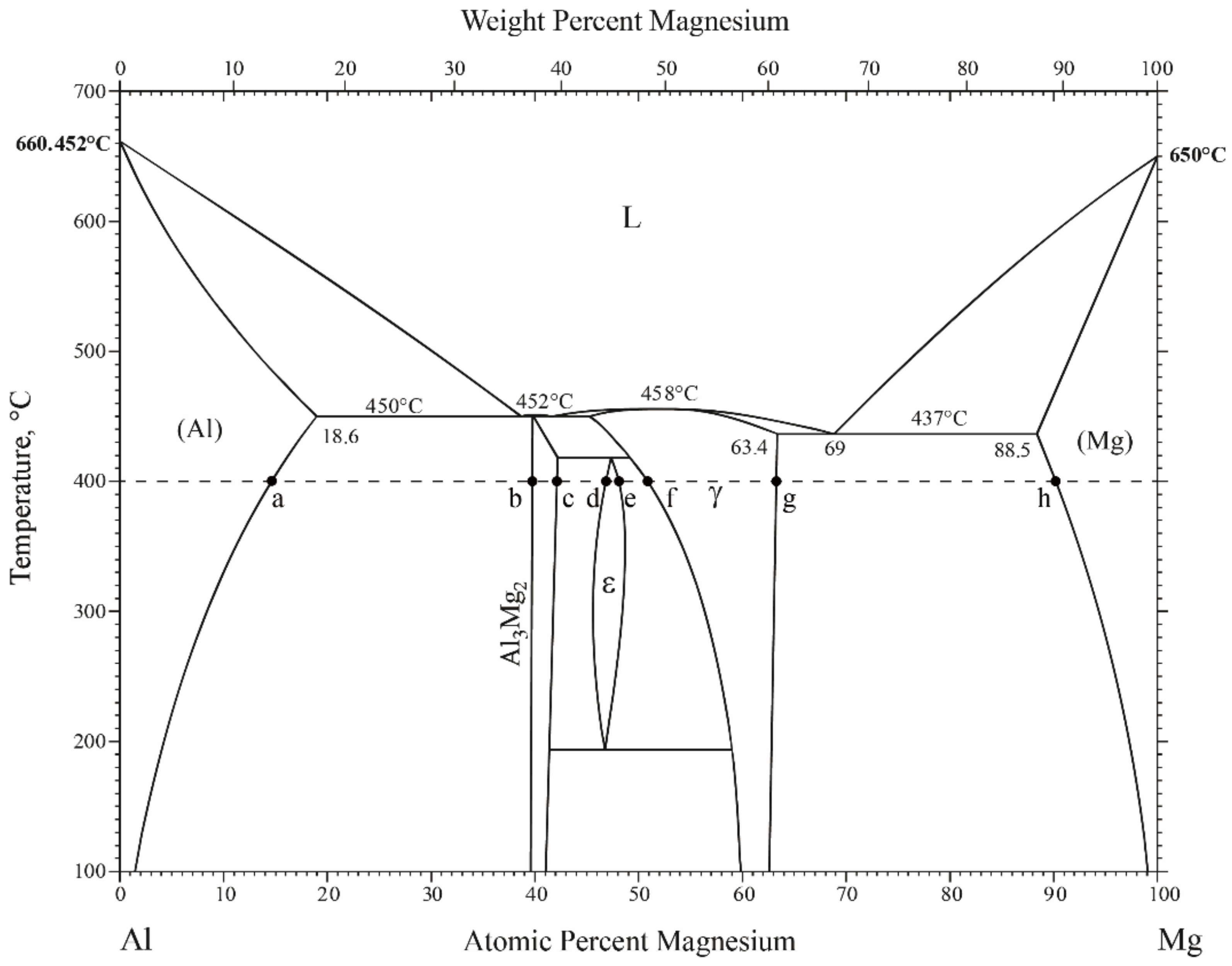
According to the Al–Mg phase diagram (Figure 3), with increasing Al concentration, transition to Al-rich intermetallic phases at the treatment temperature of 400 °C follows: α-Mg → γ-Mg17Al12 → ε-MgxAly → β-Mg2Al3 → α-Al. Apparently, γ phase endures much more significant variation in composition than β or ε phase does. Therefore, the inner layer of the formed coating is most likely to be composed of γ-Mg17Al12 phase, whilst the outer layer consists of either ε or β phase. The quantitative EDS analysis at marked positions (Table 1) provides detailed evidence: Mg atomic percentage of the inner layer ranges from 53.7% to 57.4%, overlapping the γ phase region; the outer layer contains Mg around 40 at.%, which is consistent with that of β-Mg2Al3 rather than ε phase. Moreover, the ε phase is believed to be stable only at high temperature; as is shown in the phase diagram, the equilibrium region of ε terminates at eutectoid transformation temperature around 200 °C.
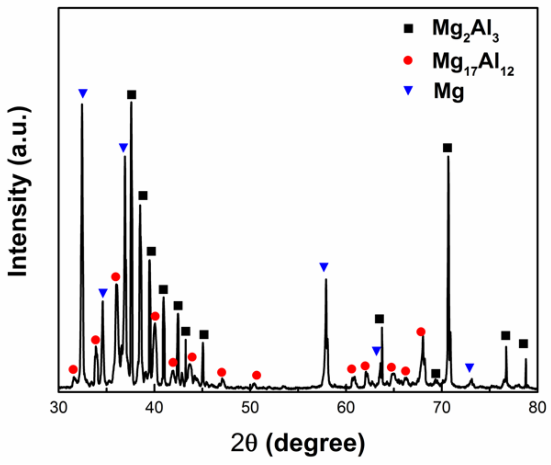
The resulting spectrum of X-ray diffraction (XRD) with Cu-Kα radiation for the as-synthesized coatings on the AZ91D specimen after 10 h immersion in AlCl3-NaCl molten salts, which is given in Figure 4, further reveals that the coatings consist of both Mg17Al12 (bcc structure, a = b = c = 10.56 Å) and Mg2Al3 (fcc structure, a = b = c = 28.239 Å) phases [45]. Hence, based on both compositional (EDS) and structural (XRD) data, we confirm that the inner and outer layers are composed the Mg-enriched Mg17Al12 and the Al-enriched Mg2Al3 phases, distinctively. This result, which has not been reported in other one-step processes before by other research groups, is coincident with that of multi-step processes, where Al coatings are prefabricated via, e.g., electroplating [35] and cold spray [34,46]. In this case, the molten salt process achieves the same phase structure as aforementioned multi-step processes did, yet through a single step other than heat treatment of prefabricated Al.
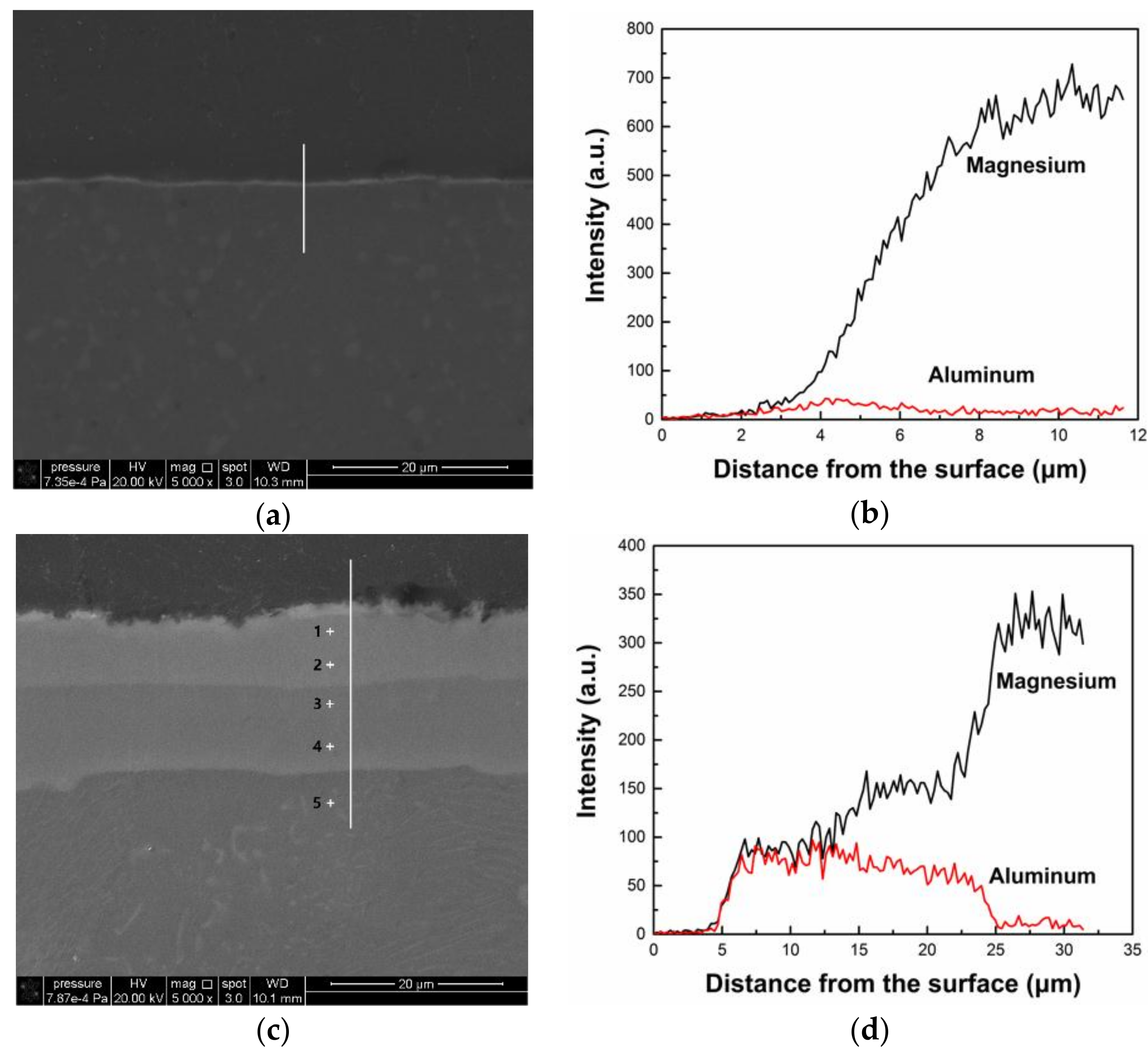
In order to figure out the formation process of the Al-alloyed coating, the molten salt treatment of AZ91D Mg alloy was carried out separately for two hours and six hours, where other condition parameters remained unchanged. Figure 5 shows the cross-sectional SEM images at the same magnification of Figure 2b and corresponding EDS line scanning spectra for the specimens of the two treatment periods. Both the conditions produce continuous coatings on the surface of the Mg alloy substrate. However, the coatings formed after 2 h immersion in the molten salts (the light line at the boundary between the substrate and the epoxy as shown in Figure 5a) is relatively thin (about four micrometers) compared to the coatings formed after prolonged periods. There is no multi-layered structure and only one layer could be observed. The EDS result (Figure 5b) exhibits an Al concentration about 17.4 at.% at the coatings, which is clearly higher than the Al concentration of the substrate. Compared to Figure 2, it is seen that 2 h treatment is insufficient for the formation of the Al-alloyed coatings with complete structure. The coatings formed at six hours (Figure 5c), on the contrary, exhibits a two-layer structure which is similar to the coating structure at 10 h. The EDS line scanning spectrum (Figure 5d) also displays three distinctive zones corresponding to the outer bright layer with mild fluctuation, the inner dark layer with wide compositional distribution, and the Mg substrate. Detailed atomic concentration data at specific points are provided in Table 2. The Mg concentration of the outer layer fluctuates at about 40 at.%, whereas it ranges from about 53 at.% to 57 at.% for the inner layer, indicating the outer layer to be β-Mg2Al3 and the inner layer to be γ-Mg17Al12. These strong evidences convey the information that the coatings formed at six hours consist of completely the same composition and structure as the coatings formed at 10 h. As the immersion time increased, the thickness of the coatings increased as well. When comparing Figure 2b and Figure 5c, it could be found that the ratio of the thicknesses of the two layers changed during the prolonged duration. The total thickness of the Al-alloyed coatings at six hours is about 20 μm, where the inner layer (about 12 μm) is slightly thicker than the outer layer (about eight micrometers). At 10 h, however, the thickness of the outer layer greatly increased, reaching up to 25 μm, whilst the inner layer grew only about one to two micrometers. The order of their thicknesses reversed as a result of prolonging immersion, indicating that the two layers have different growth rates.

3.2. Formation Mechanism of the Al-Alloyed Coatings

Rolland et al. [47] proposed that AlCl3 forms AlCl 4 , a complex ion, in AlCl3-NaCl molten salt:
AlCl3 + NaCl → NaAlCl4
Displacement reaction-related active Al atoms deposit on the Mg substrate during the molten salt treatment:
3Mg + 2NaAlCl4 → 2Al + 3MgCl2 + 2NaCl
where the Gibbs free energy of reaction ΔG = −461977 + 5.071T (J mol−1), which is far below zero at the treatment temperature. Thus the overall reaction is:
3Mg + 2Al3+ → 2Al + 3Mg2+
which is thermodynamically spontaneous under aforementioned conditions.
Since the treatment was carried out below Mg–Al eutectic temperature (437 °C), the aluminizing process was dominated by solid diffusion mechanism. The diffusion process is divided into three consecutive stages, which is schematically illustrated in Figure 6:
i.
At the first stage, active Al atoms are formed on the surface of Mg alloy substrate through the chemical reaction between the substrate and Al-containing molten salt, and subsequently these Al atoms diffuse into the substrate under the motivation of chemical potential gradient, forming solid solution of Al in Mg.
ii.
Once the concentration of Al exceeds solid solubility, the α-Mg phase is transformed into γ-Mg17Al12 phase, leading to a sudden discontinuous concentration at the interface between γ-Mg17Al12 and Mg(Al) solid solution. Thereafter, γ-Mg17Al12 phase keeps growing and consequently form continuous intermetallic layer, whilst at the same time Mg atoms diffuse toward the molten salts and Al atoms toward the substrate, both driven by concentration gradient. When these Mg atoms reach the surface, they react with AlCl 4 anions, bringing new active Al atoms. When the Al atoms reach the Mg substrate, they supersaturate the Mg(Al) solid solution at the interface, forming new γ-Mg17Al12 phase. Consequently, the Mg17Al12 layer thickens as the diffusion process continuous.
iii.
The ratio of Mg/Al in γ-Mg17Al12 phase gradually shifts toward the Al-rich side, following the g to f line in Al–Mg phase diagram (Figure 3) until it reaches the border of ε–γ equilibrium region. As a result, the formation of ε phase is expected to occur on the surface. However, no ε phase was detected in coated specimens, probably owing to the eutectoid reaction [48] (ε → β + γ) during cooling or too scare the amount to be detectable. Similarly, a second β-Mg2Al3 phase layer forms on the top surface when the composition reaches β phase region. Both the two layers (i.e., the outer β and the inner γ) thicken during subsequent annealing. As shown in Figure 2, however, the growth rate of β-Mg2Al3 phase layer is obviously higher for the reason that Al has a greater diffusion coefficient than Mg.
It is worth noticing that the interfaces between each layer are plane rather than dendritic or lamellar such as obtained by conventional packed powder cementation processes [14,20,26,33]. Note that the cementation processes were usually carried out at high temperatures, i.e., above the eutectic point of γ and α-Mg phases. In such cases, the coatings are formed through local melting and recrystallization of a hypereutectic structure characterized by the blending of primary γ-Mg17Al12 phase and α-Mg phase [28]. On the contrary, the molten salt treatment, which is carried out at relatively low temperature, produces continuous protective coatings of uniform thickness without melting of solid phases. The coatings consist of two distinct layers whose growth are controlled by reaction diffusion process, where the absence of gaps at the planar interfaces (Figure 2b) suggests strong adherence to the substrate Mg alloy.

3.3. Electrochemical Corrosion Characterization

3.3.1. Electrochemical Impedance Spectroscopy (EIS)

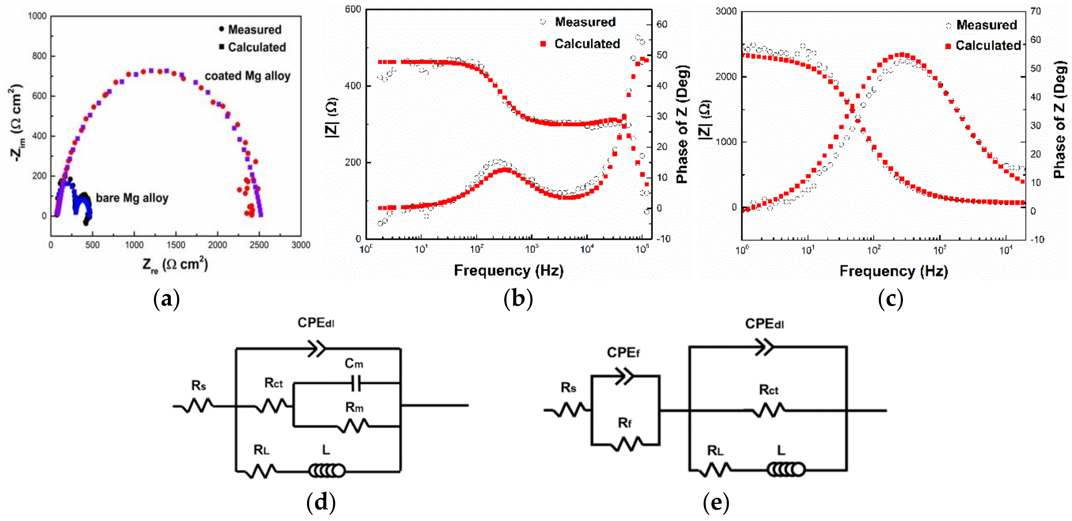
The corrosion kinetics of the bare and coated Mg alloy were investigated at first via EIS in a 3.5 wt.% NaCl solution. The test was started after 1000 s when the specimen was immersed into the solution. Figure 7a displays the typical electrochemical impedance spectra in Nyquist plots of the treated and untreated specimens. There exist two capacitive loops in the untreated specimen, whereas only one capacitive loop occurs in the treated specimen. During the test, the potential dependent electrochemical reactions at the interface between the solution and electrode is related to the charge transfer resistance (Rt) of an electrode, which is represented by the diameter of the first capacitive loop in the high frequency region. Typically, a larger distance or diameter indicates lower corrosion rate of the electrode and vice versa [49]. Compared to the untreated AZ91D specimen, the treated one is characterized by a spectrum with almost ten times large diameter, which indicates the much improved corrosion resistance by molten salt treatment. The EIS data were also processed into Bode plots (Figure 7b,c). The peak of phase angle for the coated alloy occurs at medium frequency from 102 to 103 Hz, while for the bare substrate, not only a peak at the same frequency range occurs but another “half” peak also occurs at high frequency. It is reasonable to believe that the double-peak pattern corresponds to the two capacitive loops in Nyquist plots, so that there are at least two reactions in the case of the bare metal [50]. In addition, impedance modulus of the AZ91D alloy at low frequency range raise up to about five times high of the original value after the molten salt treatment, which indicates enhanced corrosion resistance under static corrosion conditions. According to the above amplitude–frequency response (AFR) characteristics of impedance for the bare and coated AZ91D specimens, their electrical equivalent circuits (EEC) were introduced as Figure 7d,e, respectively [51,52]. The EECs in circuit description code (CDC) are Rs(CPEdl(Rct(CmRm))(RLL)) for the bare substrate and Rs(CPEfRf)(CPEdlRct(RLL)) for the coated specimen, where Rs as mentioned above refers to the solution resistance, CPEdl refers to the constant phase element of electrical double layer at the interface between the working electrode and the electrolyte, Rct refers to the charge transfer resistance, Cm (mass transfer capacitance) and Rm (mass transfer resistance) are correlated to the mass transfer of the transition product Mg+, RL (inductance resistance) and L (inductance) are correlated to corrosion nucleation and thus pitting resistance, CPEf refers to the constant phase element for the coated film, and Rf refers to the surface film resistance. The EECs can be applied to explain the electrochemical mechanism and how the Nyquist and Bode plots are generated. When the bare Mg alloy is immersed in the solution, the Faradaic process at low frequency includes both charge transfer and mass transfer reactions. In this case, the electrochemical system can be characterized by the EEC shown in Figure 7d. Compared to the Bode plots (Figure 7b) of bare Mg alloy, the phase angle (Figure 7c) and peak width of coated Mg alloy at medium frequency increased commensurate with the (CPEfRf) in its EEC. Values of equivalent elements in the EECs were calculated using ZsimpWin software, and they are listed in Table 3. As shown in Figure 7, the EEC fitting curves are well consonant with the experimental data. Therefore, the EECs can accurately present the electrochemical characteristics of the molten-salts treated and untreated AZ91D Mg alloy in 3.5 wt.% NaCl solution. According to the EECs, Rf + Rct, which is the intrinsic property of the electrode, is equal to the diameter of the first capacitive loop in Nyquist plots, and Rs, which alters with the solution, is equal to the left intercept on Zre axis, while in Bode plots it is Rs + Rf + Rct that the impedance modulus at low frequency represents. Since the anticorrosion performance is positively correlated to the diameter of capacitive loop or the impedance modulus at low frequency, we expected to obtain large Rf and Rct [49,53]. The Rct for the coated Mg alloy specimen was 2119 Ω cm2, while the Rct for the uncoated was 557 Ω cm2. The Rct increased by 3.8 times. In comparison, in the same 3.5 wt.% NaCl solution the Rct increased by about 2.2 times for the Mg–Al couple diffusion coatings (Yang et al., 2011 [36]) of the same continuous double-layer structure (i.e., the outer Mg2Al3 and the inner Mg17Al12) on AZ91D Mg alloy. Hence we confirm that the molten salt treatment as a protective process is very satisfying.

3.3.2. Localized Electrochemical Impedance Spectroscopy (LEIS)

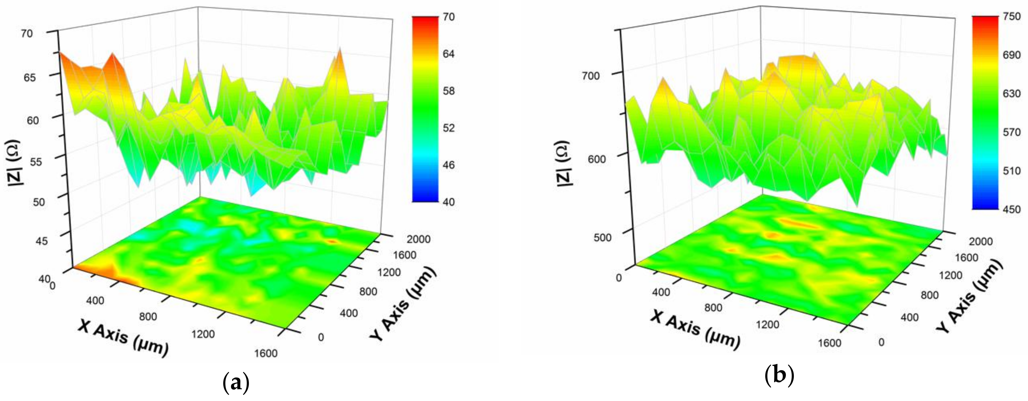
LEIS as a localized electrochemical analysis technique is an especially useful tool for monitoring localized corrosion behaviors and detecting surface defects. Figure 8 shows the results of LEIS mapping of impedance over treated and untreated AZ91D specimens. It relates the impedance modulus |Z| to the position of scanning probe: X and Y axes are scales for the surface of the electrode specimens, and Z axis the impedance modulus. The ac perturbation frequency was set at 10 Hz, constantly. When the untreated AZ91D specimen was employed as working electrode (Figure 8a), the impedance value was relatively low with an average impedance value of 56.5 Ω. After the specimen was treated in Al-containing molten salt (Figure 8b), i.e., the continuous intermetallic compound coating served as the working electrode, there was a significant increase in the impedance value (average |Z| value was about 624.3 Ω), indicating that the corrosion resistance of the specimen was greatly enhanced by the continuous diffusion coating. Both the |Z| values of the coated and uncoated specimens fluctuate randomly all over the surface areas. According to their corresponding EECs in Figure 7, the |Z| values at such low frequency as 10 Hz are correlated to the Rct, Rf and Rs. Since the solution is relatively stable during the short immersion time, the contribution of Rs to the distribution of |Z| values can be omitted. Hence the |Z| values are predominately commensurate with Rct and Rf, which alter with the composition or thickness of the coatings. The specimen can be divided into a matrix with many separate subareas each of its own EEC, in the assumption that the |Z| value in LEIS map reflects only the impedance of local area around the particular position where the platinum tip locates. Then the fluctuations reflect the local surface composition or coating thickness. As Figure 8a shows, the |Z| value of the bare Mg alloy ranges from 46 Ω to 64 Ω. In comparison, the |Z| value of the Al-alloyed specimen (Figure 8b) increased by one order of magnitude, whereas the fluctuation amplitude is relatively narrow (about 150 Ω). Therefore, the coating is even and homogenous. More importantly, on the bare metal the |Z| value at X = 0–600 μm and Y = 0–200 μm is exceptionally high, coupled with the exceptionally low value at X = 400–800 μm and Y = 1200–1600 μm. It is highly possible that there forms a galvanic cell, where the high |Z| zone serves as the cathodic (less corrosion reactive) and the low |Z| zone as the anodic (more corrosion reactive) [54]. This feature was not detected in the coated Mg alloy, so that the coating is defect-free and effective in inhibition of localized corrosion.
Since the oxidation potential for typical Mg-based alloys is around −1.5 V (vs. SCE) [54], the main cathodic reaction of AZ91D in NaCl solution is reduction of water (E° = −1.1077 V, vs. SCE) rather than dissolved oxygen (E° = 0.121 V, vs. SCE) [55].
Overall reaction: Mg + 2H2O → Mg(OH)2 + H2
Cathode: 2H2O + 2e → 2OH + H2
Anode: Mg → Mg2+ + 2e
The corrosion is accompanied with local alkalization and hydrogen evolution. During the LEIS test, no hydrogen evolution was detected by naked eyes for the coated Mg alloy, whilst hydrogen bubbles were found on the uncoated. Therefore, the coating is compact, continuous and inactive in NaCl solution, well agreeing with the LEIS map.

3.3.3. Scanning Vibrating Electrode Technique (SVET)

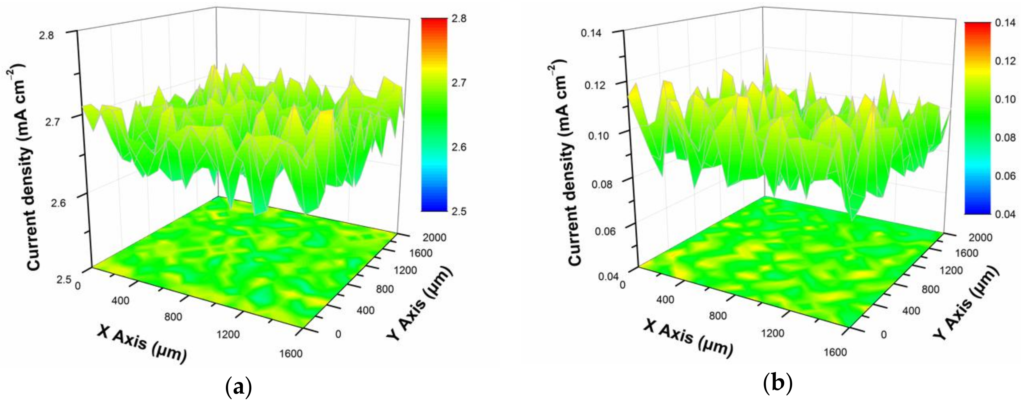
Further investigation into the localized corrosion resistance properties of the coating fabricated via molten salt treatment was carried out by SVET analysis. SVET is frequently applied as a method for fast screening of local corrosion behaviors. The scanning probe was positioned at 100 μm and the vibration amplitude was 30 μm. Localized ionic current densities of coated/uncoated specimens to the positions on the surface are shown in Figure 9, which consists of a color map with projection for each specimen. Significant differences between the corrosion behaviors of bare and coated Mg alloy can be observed. The current density of the coated Mg alloy (Figure 9a) significantly decreased to 0.07–0.11 mA cm−2, with an average approximately 3.8% of the value of the bare metal (2.6–2.7 mA cm−2). The corrosion potential of the Mg alloy to the platinum probe is around −2.4 V, while the oxidation potential of water is 0.049 V (vs. Pt) and of OH is −0.779 V (vs. Pt) [54,55]. Thus the current density which is induced by ionic fluxes predominately reflects the dissolution of surface Mg, namely the corrosion reactivity. The lower current density indicates that the Al-alloyed specimen has improved ability to withstand severe corrosion. On the other hand, it is believed that the high corrosion reactivity of bare AZ91D Mg alloy could be attributed to the instability of the protective oxide layer formed on the exposed Mg surface in the early stages of immersion in chloride-containing electrolyte [56]. The SVET could provide unique information that was not included in the LEIS results. According to the EECs, in the case of SVET where the input is dc voltage, the output current density is proportional to the Rct value, which characterizes corrosion at static condition. In other words, the output does not change with the frequency. In the case of LEIS, however, the output responds to the input ac frequency, so that the |Z| value is different at low and high frequencies. Even though LEIS can approximately reflect static corrosion at low frequency, the SVET results should be more accurate. In addition, while in the case of LEIS the |Z| value at particular zone is also effected by the block properties of the specimen electrode, the SVET results only concern the instant reactions happening on the electrode surface. Therefore, the SVET has higher resolution for characterization of local corrosion reactions at areas with defects. The generally even current density distribution of the coated Mg alloy suggests that the Al-alloyed coating is defect-free, continuous and of good homogeneity, which well agrees with the EIS and LEIS results. However, local current fluctuations occur for both the coated and uncoated Mg alloys. As for the absolute value of fluctuation amplitude, the current density of the coated specimen fluctuates more mildly (amplitude = 0.02 mA) than the current density of the uncoated (amplitude = 0.05 mA), indicating that the coating inhibits pitting corrosion. However, the coated specimen exhibits a ratio of fluctuation about 20% to the average current density, while the ratio is about two percent for the uncoated substrate. The substrate was carefully polished before the test. Hence, the relatively large fluctuation might be attributed to micro unevenness on the coatings formed in the AlCl3-NaCl molten salts. Nevertheless, the real unevenness might not be so obvious with regard to the existence of systematic errors.

4. Conclusions

A continuous layer consisted of homogeneously distributed intermetallic phases was fabricated on the surface of AZ91D magnesium alloy via diffusion coating treatment in Al-containing molten salt at 400 °C. The coatings are comprised of a multilayer structure with the outer Mg2Al3 and inner Mg17Al12 phase layer, which are formed by the displacement reaction and subsequent reaction–diffusion process. Localized electrochemical characterization techniques show that the formed intermetallic compounds coating is continuous without defects, leading to a significant suppression of the corrosion processes of underlying Mg alloy substrate. It is demonstrated that diffusion coating treatment of Mg alloys in Al-containing molten salts is an effective and promising one-step approach to prepare protective intermetallic surface layer and thus to improve the corrosion resistance of substrate Mg alloys.

Acknowledgments

This work was supported by the National Nature Science Foundation for Excellent Young Scholar (51722403), the National Youth Talent Support Program, and the National Nature Science Foundation of China (51374005 and 51004070).

Author Contributions

Cheng Zhong and Wenbin Hu conceived and designed the experiments; Xu Chen and Bin Liu performed structural and composition characterizations experiments; Xiaopeng Han and Yida Deng performed global and localized electrochemical experiments; Zhenxuan Fu and Jie Liu analyzed the data; Zhenxuan Fu wrote the paper.

Conflicts of Interest

The authors declare no conflict of interest.

References

  1. Zhu, B.; Wang, S.; Wang, L.; Yang, Y.; Liang, J.; Cao, B. Preparation of hydroxyapatite/tannic acid coating to enhance the corrosion resistance and cytocompatibility of AZ31 magnesium alloys. Coatings 2017, 7, 105. [Google Scholar] [CrossRef]
  2. Aghion, E.; Bronfin, B. Magnesium alloys development towards the 21st century. Mater. Sci. Forum 2000, 350, 19–28. [Google Scholar] [CrossRef]
  3. Staiger, M.P.; Pietak, A.M.; Huadmai, J.; Dias, G. Magnesium and its alloys as orthopedic biomaterials: A review. Biomaterials 2006, 27, 1728–1734. [Google Scholar] [CrossRef] [PubMed]
  4. Mordike, B.L.; Ebert, T. Magnesium—Properties—Applications—Potential. Mater. Sci. Eng. A 2001, 302, 37–45. [Google Scholar] [CrossRef]
  5. Cheng, Y.L.; Qin, T.W.; Wang, H.M.; Zhang, Z. Comparison of corrosion behaviors of AZ31, AZ91, AM60 and ZK60 magnesium alloys. Trans. Nonferrous Met. Soc. 2009, 19, 517–524. [Google Scholar] [CrossRef]
  6. Song, G. Control of biodegradation of biocompatable magnesium alloys. Corros. Sci. 2007, 49, 1696–1701. [Google Scholar] [CrossRef]
  7. Song, G.L.; Atrens, A. Corrosion mechanisms of magnesium alloys. Adv. Eng. Mater. 1999, 1, 11–33. [Google Scholar] [CrossRef]
  8. Atrens, A.; Song, G.L.; Liu, M.; Shi, Z.; Cao, F.; Dargusch, M.S. Review of recent developments in the field of magnesium corrosion. Adv. Eng. Mater. 2015, 17, 400–453. [Google Scholar] [CrossRef]
  9. Espinosa, T.; Sanes, J.; Bermudez, M.D. Halogen-free phosphonate ionic liquids as precursors of abrasion resistant surface layers on AZ31B magnesium alloy. Coatings 2015, 5, 39–53. [Google Scholar] [CrossRef]
  10. Upadhyay, V.; Bergseth, Z.; Kelly, B.; Battocchi, D. Silica-based sol-gel coating on magnesium alloy with green inhibitors. Coatings 2017, 7, 86. [Google Scholar] [CrossRef]
  11. Esmaily, M.; Svensson, J.E.; Fajardo, S.; Birbilis, N.; Frankel, G.S.; Virtanen, S.; Arrabal, R.; Thomas, S.; Johansson, L.G. Fundamentals and advances in magnesium alloy corrosion. Prog. Mater. Sci. 2017, 89, 92–193. [Google Scholar] [CrossRef]
  12. Song, G.L.; Atrens, A.; Dargusch, M. Influence of microstructure on the corrosion of diecast AZ91D. Corros. Sci. 1999, 41, 249–273. [Google Scholar] [CrossRef]
  13. Lunder, O.; Lein, J.E.; Aune, T.K.; Nisancioglu, K. Role of Mg17Al12 phase in the corrosion of Mg alloy AZ91. Corrosion 1989, 45, 741–748. [Google Scholar] [CrossRef]
  14. Zhu, L.; Song, G. Improved corrosion resistance of AZ91D magnesium alloy by an aluminium-alloyed coating. Surf. Coat. Technol. 2006, 200, 2834–2840. [Google Scholar] [CrossRef]
  15. Li, X.; Liang, W.; Zhao, X.; Zhang, Y.; Fu, X.; Liu, F. Bonding of Mg and Al with Mg–Al eutectic alloy and its application in aluminum coating on magnesium. J. Alloys Compd. 2009, 471, 408–411. [Google Scholar] [CrossRef]
  16. Chang, H.W.; Zhang, M.X.; Atrens, A.; Huang, H. Nanomechanical properties of Mg–Al intermetallic compounds produced by packed powder diffusion coating (PPDC) on the surface of AZ91E. J. Alloys Compd. 2014, 587, 527–532. [Google Scholar] [CrossRef] [Green Version]
  17. Elahi, M.R.; Sohi, M.H.; Safaei, A. Liquid phase surface alloying of AZ91D magnesium alloy with Al and Ni powders. Appl. Surf. Sci. 2012, 258, 5876–5880. [Google Scholar] [CrossRef]
  18. Hirmke, J.; Zhang, M.X.; St John, D.H. Influence of chemical composition of Mg alloys on surface alloying by diffusion coating. Metall. Mater. Trans. A 2012, 43, 1621–1628. [Google Scholar] [CrossRef]
  19. Mola, R. The properties of Mg protected by Al- and Al/Zn-enriched layers containing intermetallic phases. J. Mater. Res. 2015, 30, 3682–3691. [Google Scholar] [CrossRef]
  20. Shigematsu, I.; Nakamura, M.; Saitou, N.; Shimojima, K. Surface treatment of AZ91D magnesium alloy by aluminum diffusion coating. J. Mater. Sci. Lett. 2000, 19, 473–475. [Google Scholar] [CrossRef]
  21. Zhang, M.X.; Kelly, P.M. Surface alloying of AZ91D alloy by diffusion coating. J. Mater. Res. 2002, 17, 2477–2479. [Google Scholar] [CrossRef]
  22. Hirmke, J.; Zhang, M.X.; StJohn, D.H. Surface alloying of AZ91E alloy by Al–Zn packed powder diffusion coating. Surf. Coat. Technol. 2011, 206, 425–433. [Google Scholar] [CrossRef]
  23. Park, J.S.; Kim, J.M.; Kim, H.Y.; Kang, C.S.; Choi, S.W. Surface protection of magnesium alloys via pack cementation coatings with aluminum powder and chlorides. Mater. Sci. Forum 2010, 638–642, 793–798. [Google Scholar] [CrossRef]
  24. Christoglou, C.; Voudouris, N.; Angelopoulos, G.N.; Pant, M.; Dahl, W. Deposition of aluminium on magnesium by a CVD process. Surf. Coat. Technol. 2004, 184, 149–155. [Google Scholar] [CrossRef]
  25. Chen, W.; He, Y.; Gao, W. Al diffusion coating on Mg alloy by a surface nanocrystallization enhanced CVD process. Int. J. Smart Nano Mater. 2010, 1, 288–293. [Google Scholar] [CrossRef]
  26. Liu, F.; Liang, W.; Li, X.; Zhao, X.; Zhang, Y.; Wang, H. Improvement of corrosion resistance of pure magnesium via vacuum pack treatment. J. Alloys Compd. 2008, 461, 399–403. [Google Scholar] [CrossRef]
  27. Zhang, Y.; Liang, W.; Wang, H.; Liu, F.; Li, X.; Zhao, X. Research on microstructure and properties of aluminum alloyed coating on AZ91D magnesium alloy by vacuum solid diffusion. Rare Met. Mater. Eng. 2008, 37, 2023–2026. [Google Scholar] [CrossRef]
  28. Liu, F.; Li, X.; Liang, W.; Zhao, X.; Zhang, Y. Effect of temperature on microstructures and properties of aluminized coating on pure magnesium. J. Alloys Compd. 2009, 478, 579–585. [Google Scholar] [CrossRef]
  29. Mola, R. Fabrication and microstructure of diffusion alloyed layers on pure magnesium substrate. Arch. Metall. Mater. 2014, 59, 1409–1412. [Google Scholar] [CrossRef]
  30. Jun, Y.; Sun, G.P.; Wang, H.Y.; Jia, S.Q.; Jia, S.S. Laser (Nd:YAG) cladding of AZ91D magnesium alloys with Al + Si + Al2O3. J. Alloys Compd. 2006, 407, 201–207. [Google Scholar] [CrossRef]
  31. Jun, Y.; Sun, G.P.; Jia, S.S. Characterization and wear resistance of laser surface melting AZ91D alloy. J. Alloys Compd. 2008, 455, 142–147. [Google Scholar] [CrossRef]
  32. Ignat, S.; Sallamand, P.; Grevey, D.; Lambertin, M. Magnesium alloys laser (Nd:YAG) cladding and alloying with side injection of aluminium powder. Appl. Surf. Sci. 2004, 225, 124–134. [Google Scholar] [CrossRef]
  33. Sun, H.Q.; Shi, Y.N.; Zhang, M.X.; Lu, K. Surface alloying of an Mg alloy subjected to surface mechanical attrition treatment. Surf. Coat. Technol. 2008, 202, 3947–3953. [Google Scholar] [CrossRef]
  34. Spencer, K.; Zhang, M.X. Heat treatment of cold spray coatings to form protective intermetallic layers. Scr. Mater. 2009, 61, 44–47. [Google Scholar] [CrossRef]
  35. Yang, H.; Guo, X.; Wu, G.; Ding, W.; Birbilis, N. Electrodeposition of chemically and mechanically protective Al-coatings on AZ91D Mg alloy. Corros. Sci. 2011, 53, 381–387. [Google Scholar] [CrossRef]
  36. Yang, H.; Guo, X.; Wu, G.; Wang, S.; Ding, W. Continuous intermetallic compounds coatings on AZ91D Mg alloy fabricated by diffusion reaction of Mg–Al couples. Surf. Coat. Technol. 2011, 205, 2907–2913. [Google Scholar] [CrossRef]
  37. Ishibashi, Y.; Nose, M.; Hatakeyama, M.; Sunada, S. Effects of aluminum sputtering on the corrosion resistance of AZ91 alloy. Arch. Metall. Mater. 2015, 60, 953–955. [Google Scholar] [CrossRef]
  38. Smolik, J.; Mazurkiewicz, A.; Kacprzyńska-GoŁacka, J.; Rydzewski, M.; Szota, M.; Mizera, J. Composite layers “MgAl intermetalic layer/PVD coating” obtained on the AZ91D magnesium alloy by different hybrid surface treatment methods. Arch. Metall. Mater. 2015, 60, 1031–1035. [Google Scholar] [CrossRef]
  39. Liu, F.; Chen, X.; Gu, Y.; Ma, C.; Han, X.; Deng, Y.; Hu, W.; Zhong, C. Effect of pretreatment and annealing on aluminum coating prepared by physical vapor deposition on AZ91D magnesium alloys. Int. J. Electrochem. Sci. 2016, 11, 5655–5668. [Google Scholar] [CrossRef]
  40. Lillard, R.S. A novel method for generating quantitative local electrochemical impedance spectroscopy. J. Electrochem. Soc. 1992, 139, 1007–1012. [Google Scholar] [CrossRef]
  41. Zhang, G.A.; Cheng, Y.F. Micro-electrochemical characterization of corrosion of welded X70 pipeline steel in near-neutral pH solution. Corros. Sci. 2009, 51, 1714–1724. [Google Scholar] [CrossRef]
  42. Jorcin, J.B.; Aragon, E.; Merlatti, C.; Pébère, N. Delaminated areas beneath organic coating: A local electrochemical impedance approach. Corros. Sci. 2006, 48, 1779–1790. [Google Scholar] [CrossRef] [Green Version]
  43. Huang, V.M.; Wu, S.L.; Orazem, M.E.; Pébre, N.; Tribollet, B.; Vivier, V. Local electrochemical impedance spectroscopy: A review and some recent developments. Electrochim. Acta 2011, 56, 8048–8057. [Google Scholar] [CrossRef] [Green Version]
  44. Okamoto, H. Supplemental literature review of binary phase diagrams: Al–Mg, Bi–Sr, Ce–Cu, Co–Nd, Cu–Nd, Dy–Pb, Fe–Nb, Nd–Pb, Pb–Pr, Pb–Tb, Pd–Sb, and Si–W. J. Phase Equilib. Diffus. 2015, 36, 183–195. [Google Scholar] [CrossRef]
  45. Massalski, T.B.; Okamoto, H.; Subramanian, P.R.; Kacprzak, L. Binary Alloy Phase Diagrams; American Society for Metals: Geauga County, OH, USA, 1986; ISBN 087170403X. [Google Scholar]
  46. Bu, H.; Yandouzi, M.; Lu, C.; Jodoin, B. Effect of heat treatment on the intermetallic layer of cold sprayed aluminum coatings on magnesium alloy. Surf. Coat. Technol. 2011, 205, 4665–4671. [Google Scholar] [CrossRef]
  47. Rolland, P.; Mamantoy, G. Electrochemical reduction of Al 2 Cl 7 ions in chloroaluminate melts. J. Electrochem. Soc. 1976, 123, 1299–1303. [Google Scholar] [CrossRef]
  48. Su, H.L.; Harmelin, M.; Donnadieu, P.; Baetzner, C.; Seifert, H.J.; Lukas, H.L.; Effenberg, G.; Aldinger, F. Experimental investigation of the Mg–Al phase diagram from 47 to 63 at.% Al. J. Alloys Compd. 1997, 247, 57–65. [Google Scholar] [CrossRef]
  49. Song, G.L. Effect of tin modification on corrosion of AM70 magnesium alloy. Corros. Sci. 2009, 51, 2063–2070. [Google Scholar] [CrossRef]
  50. Jin, S.; Amira, S.; Ghali, E. Electrochemical impedance spectroscopy evaluation of the corrosion behavior of die cast and thixocast AXJ530 magnesium alloy in chloride solution. Adv. Eng. Mater. 2007, 9, 75–83. [Google Scholar] [CrossRef]
  51. Meifeng, H.; Lei, L.; Yating, W.; Zhixin, T.; Wenbin, H. Corrosion properties of surface-modified AZ91D magnesium alloy. Corros. Sci. 2008, 50, 3267–3273. [Google Scholar] [CrossRef]
  52. He, M.; Liu, L.; Wu, Y.; Zhong, C.; Hu, W. Influence of microstructure on corrosion properties of multilayer Mg-Al intermetallic compound coating. Corros. Sci. 2011, 53, 1312–1321. [Google Scholar] [CrossRef]
  53. Xu, R.; Yang, X.; Suen, K.W.; Wu, G.; Li, P.; Chu, P.K. Improved corrosion resistance on biodegradable magnesium by zinc and aluminum ion implantation. Appl. Surf. Sci. 2012, 263, 608–612. [Google Scholar] [CrossRef]
  54. Karavai, O.V.; Bastos, A.C.; Zheludkevich, M.L.; Taryba, M.G.; Lamaka, S.V.; Ferreira, M.G.S. Localized electrochemical study of corrosion inhibition in microdefects on coated AZ31 magnesium alloy. Electrochim. Acta 2010, 55, 5401–5406. [Google Scholar] [CrossRef]
  55. Haynes, W.M. CRC Handbook of Chemistry and Physics, 93rd ed.; CRC Press: Boca Raton, FL, USA, 2012. [Google Scholar]
  56. Williams, G.; Neil McMurray, H. Localized corrosion of magnesium in chloride-containing electrolyte studied by a scanning vibrating electrode technique. J. Electrochem. Soc. 2008, 155, C340–C349. [Google Scholar] [CrossRef]
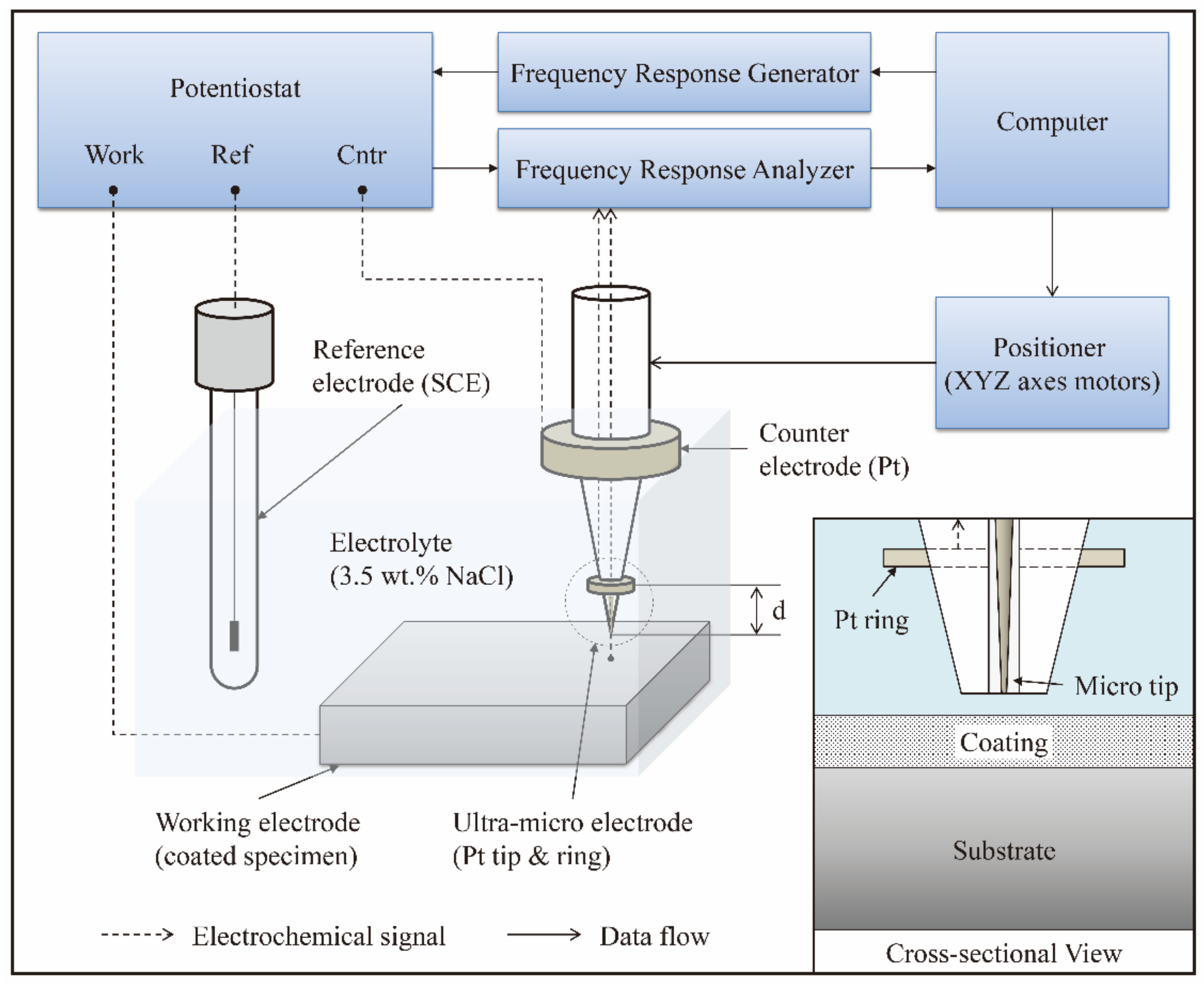
Figure 1. Schematic of the five-electrode configuration for localized electrochemical analysis. The data is collected via the potentiostat and frequency response analyzer (FRA), while experiment control is manipulated through computer and the positioner.
Coatings 08 00148 g001
Figure 2. (a) Optical image and (b) corresponding cross-sectional scanning electron microscope (SEM) micrograph with (c) Mg–Al energy dispersive X-ray spectrometry (EDS) line scanning spectra of coated AZ91D specimen with molten-salt treatment at 400 °C for 10 h.
Coatings 08 00148 g002
Figure 3. Mg–Al phase diagram [44]. Reproduced from [44] with permission. Copyright 2015 Springer Nature.
Coatings 08 00148 g003
Figure 4. XRD results for the Al-alloyed coatings on the AZ91D Mg alloy after 10 h treatment in AlCl3-NaCl molten salts.
Coatings 08 00148 g004
Figure 5. Cross-sectional SEM micrographs and corresponding EDS line scanning results for the Al-alloyed coatings on the AZ91D Mg alloy treated in AlCl3-NaCl molten salts at 400 °C: (a) SEM and (b) EDS results for the specimen after two hour treatment; (c) SEM and (d) EDS results for another specimen after six hour treatment.
Coatings 08 00148 g005
Figure 6. Schematic diagram of the formation of diffusion coatings on the Mg substrate with molten salt treatment: (a) cross-sectional view; (b) interfacial atomic view.
Coatings 08 00148 g006
Figure 7. Electrochemical impedance spectroscopy (EIS) results in (a) Nyquist plots and Bode plots for (b) the bare and (c) the coated AZ91D Mg alloys after 10 h treatment in AlCl3-NaCl molten salts measured at their open-circuit potentials in 3.5 wt.% NaCl solution, coupled with the electrical equivalent circuits (EECs) of (d) the bare and (e) the coated specimens based on the EIS data. The fitting curves in the Nyquist and Bode plots were calculated using the equivalent circuits.
Coatings 08 00148 g007
Figure 8. Localized electrochemical impedance spectroscopy (LEIS) maps of impedance over the AZ91D specimen (a) without and (b) with 400 °C, 10 h molten salt treatment, measured in 3.5 wt.% NaCl solution.
Coatings 08 00148 g008
Figure 9. Scanning vibrating electrode technique (SVET) maps of current density over the AZ91D specimen (a) without and (b) with 400 °C, 10 h molten salt treatment, measured in 3.5 wt.% NaCl solution.
Coatings 08 00148 g009
Table 1. Atomic ratios (at.%) of Mg and Al at marked positions in Figure 2b.
LocationMg (at.%)Al (at.%)Corresponding Phase
139.760.3β-Mg2Al3
241.258.8β-Mg2Al3
353.746.3γ-Mg17Al12
457.442.6γ-Mg17Al12
591.48.6Mg alloy substrate
Table 2. Atomic ratios (at.%) of Mg and Al at marked positions in Figure 5c.
LocationMg (at.%)Al (at.%)Corresponding Phase
140.459.6β-Mg2Al3
241.658.4β-Mg2Al3
352.947.1γ-Mg17Al12
456.843.2γ-Mg17Al12
591.38.7Mg alloy substrate
Table 3. The values of the elements in the EECs in Figure 7.
SpecimenCPEdl (μF cm−2)Rct (Ω cm2)
Bare AZ91D Mg alloy0.013557
Coated AZ91D Mg alloy2.62119