The Use of a Saturated Long Carbon Chain Sodium Monocarboxylate for the Corrosion Inhibition of Lead Objects in Atmospheric Conditions and in Acetic Acid Corrosive Solutions


Abstract
1. Introduction
2. Experimental
2.1. Chemicals
2.2. Preparation of the Lead Coupons
2.3. Coating Process
2.4. SEM Experiments
2.5. Coating Thickness Measurements
2.6. FTIR Measurements
2.7. LSV Measurements
2.8. EIS Measurements
3. Results and Discussion
3.1. Surface Analysis
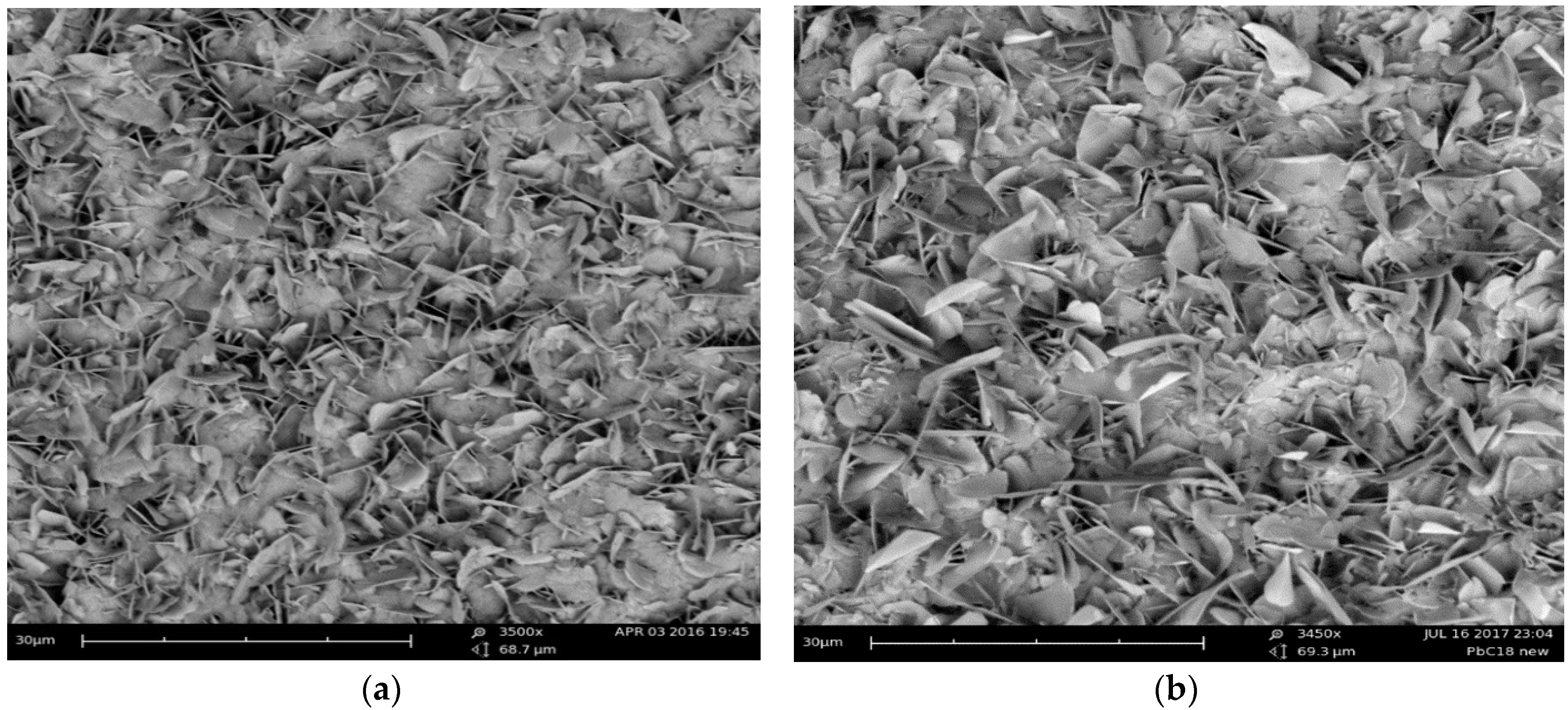
3.1.1. SEM Analysis and Coating Thickness Measurements
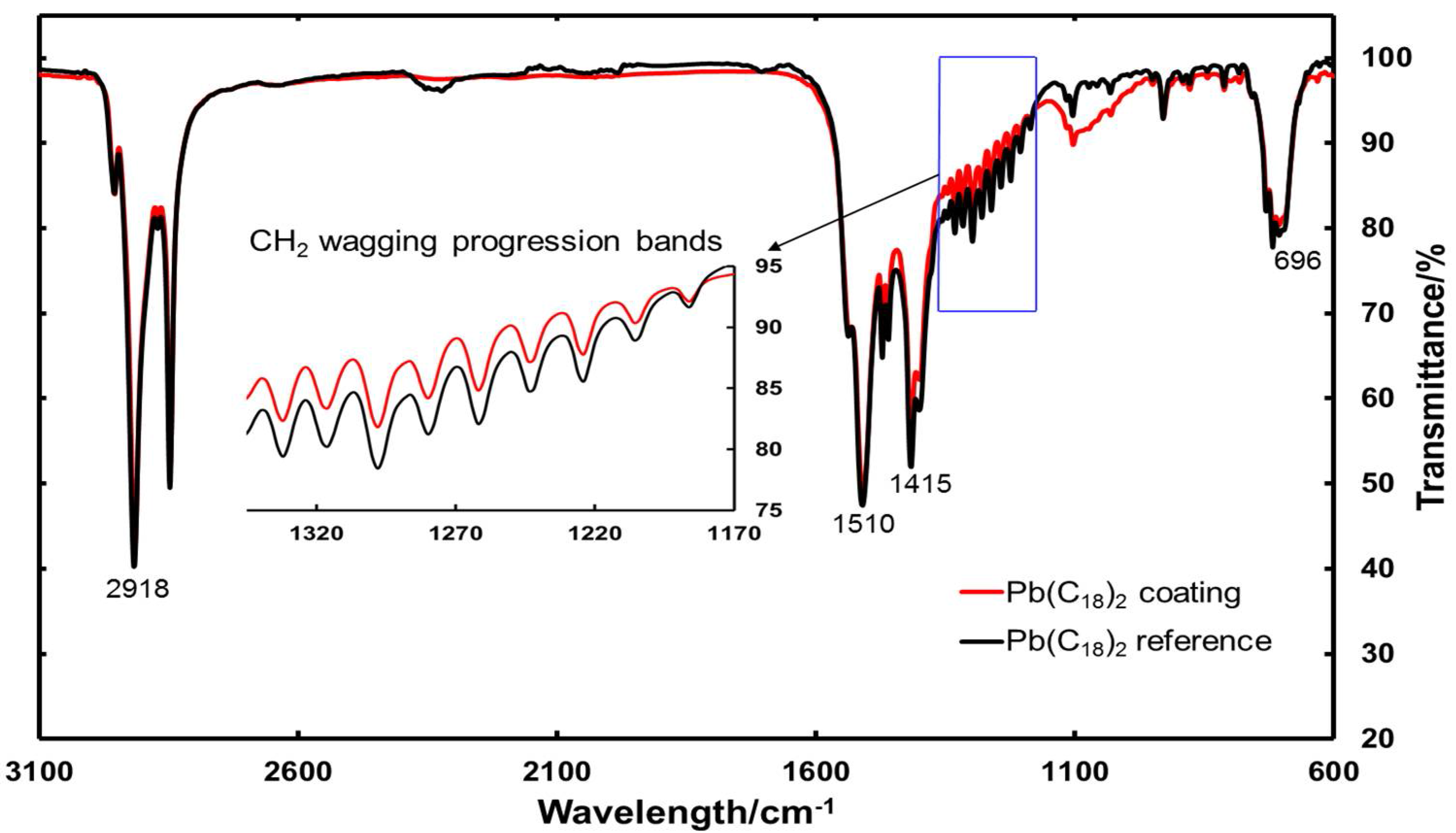
3.1.2. FTIR Measurements
3.2. Electrochemical Measurements
3.2.1. In Atmospheric Conditions
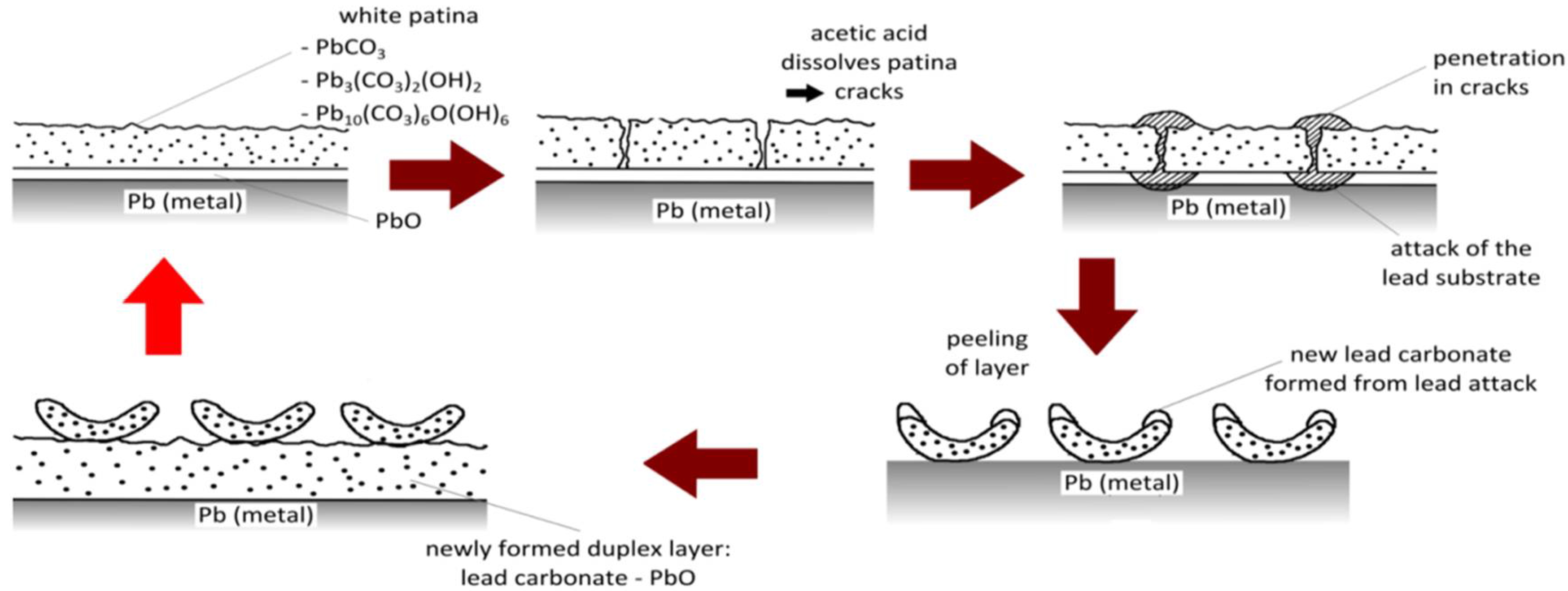
3.2.2. In an Acetic Acid Corrosive Solution
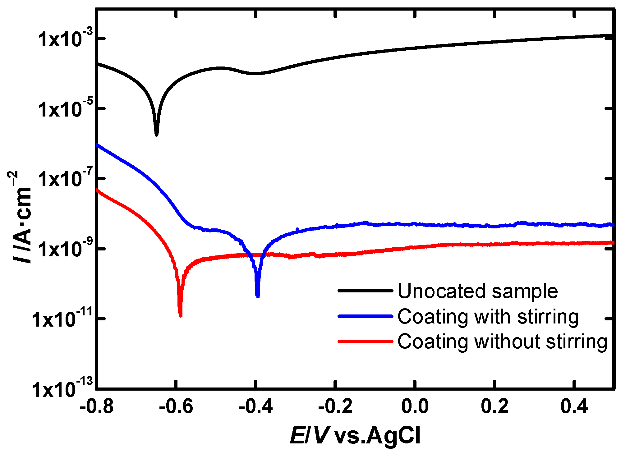
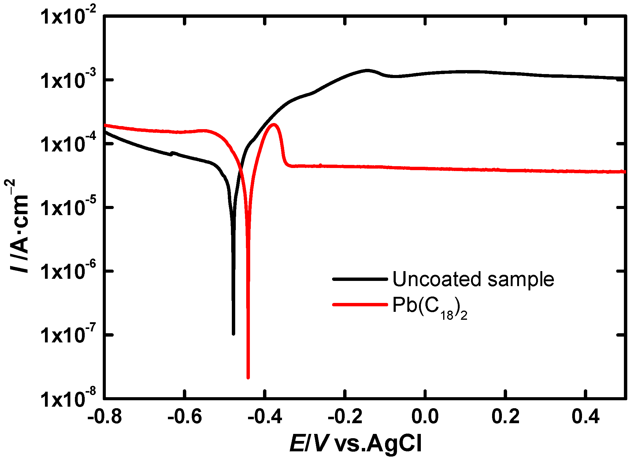
LSV Experiments
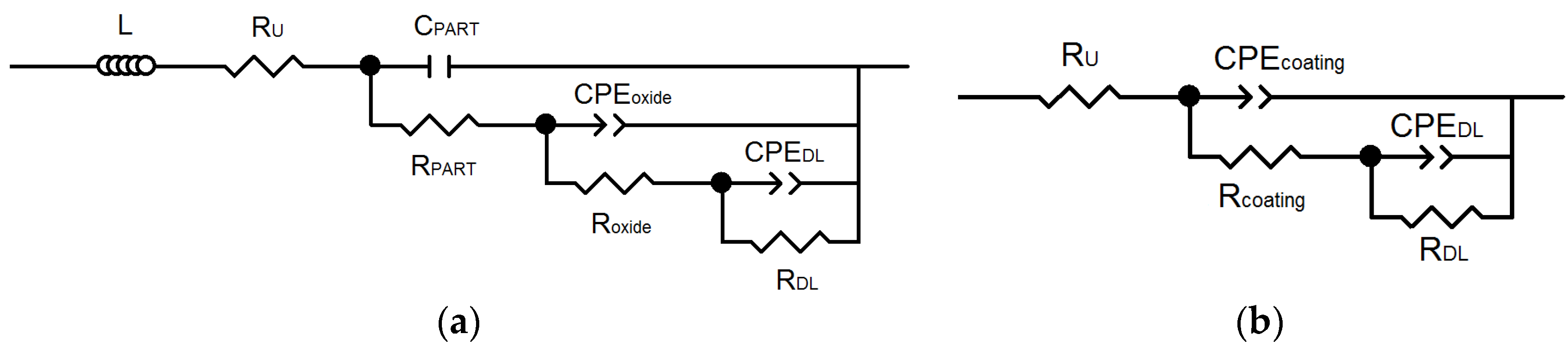
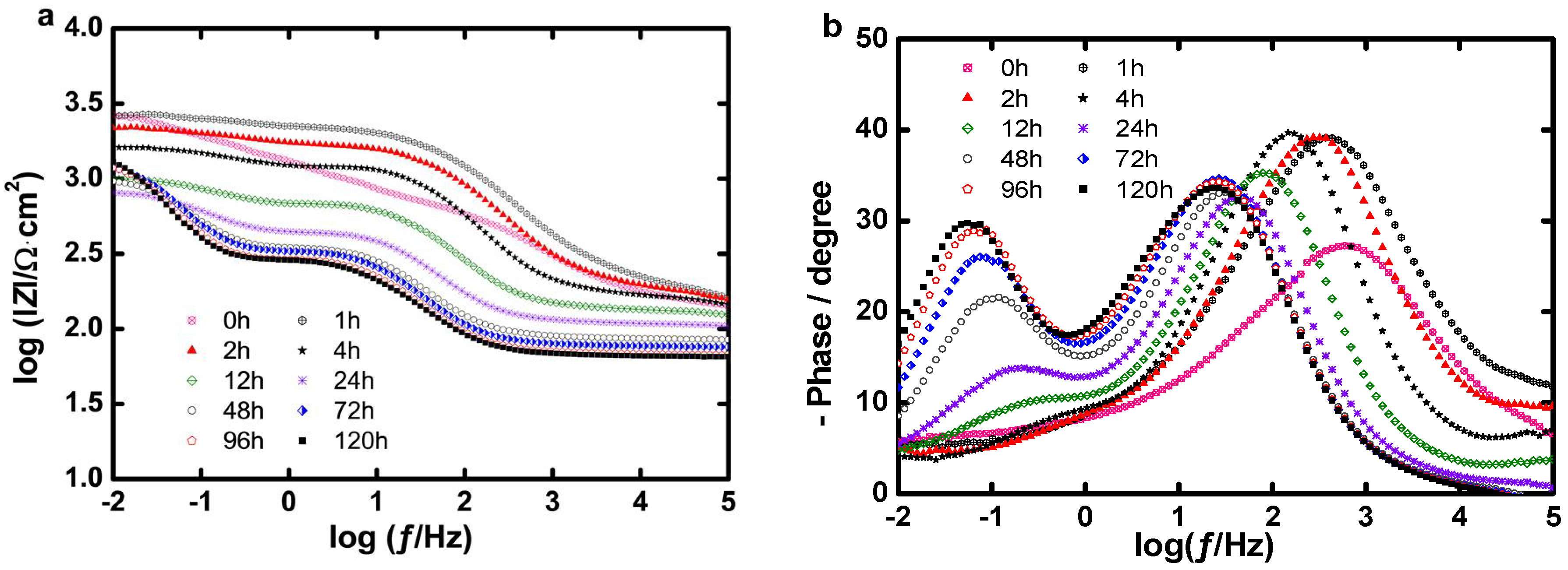
EIS Experiments
Long Term Evaluation of the Coating
4. Conclusions
Acknowledgments
Author Contributions
Conflicts of Interest
References
- Tylecote, R.F. The behaviour of lead as a corrosion resistant medium undersea and in soils. J. Archaeol. Sci. 1983, 10, 397–409. [Google Scholar] [CrossRef]
- Chiavari, C.; Martini, C.; Prandstraller, D.; Niklasson, A.; Johansson, L.G.; Svensson, J.E.; Åslund, A.; Bergsten, C.J. Atmospheric corrosion of historical organ pipes: The influence of environment and materials. Corros. Sci. 2008, 50, 2444–2455. [Google Scholar] [CrossRef]
- Donais, M.K.; Whissel, G.; Dumas, A.; Golden, K. Analyzing lead content in ancient bronze coins by flame atomic absorption spectroscopy. An archaeometry laboratory with nonscience majors. J. Chem. Educ. 2009, 86, 343–346. [Google Scholar] [CrossRef]
- Abu-baker, A.; Sekhaneh, W.A.; Shiyab, A.; Dellith, J.; Scheffel, A.; Alebrahim, M.A. Analytical investigation of five roman Pb-based scale weights (Qasr Ar-Rabbah, Jordan): A Case Study. Mediterr. Archaeol. Archaeom. 2014, 14, 181–190. [Google Scholar]
- Graedel, T. Chemical mechanisms for the atmospheric corrosion of lead. J. Electrochem. Soc. 1994, 141, 922–927. [Google Scholar] [CrossRef]
- Tranter, G.C. Patination of lead: An infra-red spectroscopic study. Br. Corros. J. 1976, 11, 222–224. [Google Scholar] [CrossRef]
- Watkinson, D. Preservation of metallic cultural heritage. In Shreir’s Corrosion; Cottis, B., Graham, M., Lindsay, R., Lyon, S., Richardson, T., Scantlebury, D., Stott, H., Eds.; Elsevier Ltd.: Amsterdam, The Netherlands, 2010. [Google Scholar]
- Grayburn, R.; Dowsett, M.; De Keersmaecker, M.; Westenbrink, E.; Covington, J.A.; Crawford, J.B.; Hand, M.; Walker, D.; Thomas, P.A.; Banerjee, D.; et al. Time-lapse synchrotron X-ray diffraction to monitor conservation coatings for heritage lead in atmospheres polluted with oak-emitted volatile organic compounds. Corros. Sci. 2014, 82, 280–289. [Google Scholar] [CrossRef]
- Niklasson, A.; Johansson, L.-G.; Svensson, J.-E. The influence of relative humidity and temperature on the acetic acid vapour-induced atmospheric corrosion of lead. Corros. Sci. 2008, 50, 3031–3037. [Google Scholar] [CrossRef]
- Niklasson, A.; Johansson, L.-G.; Svensson, J.-E. Influence of acetic acid vapor on the atmospheric corrosion of lead. J. Electrochem. Soc. 2005, 152, B519–B525. [Google Scholar] [CrossRef]
- Niklasson, A.; Johansson, L.-G.; Svensson, J.-E. Atmospheric corrosion of historical organ pipes: Influence of acetic and formic acid vapour and water leaching on lead. In Metal 04: Proceedings of the International Conference on Metals Conservation: Canberra, Australia, 4–8 October 2004; Ashton, J., Hallam, D., Eds.; National Museum of Australia: Canberra, Australia, 2004; pp. 273–280. [Google Scholar]
- Chiavari, C.; Martini, C.; Poli, G.; Prandstraller, D. Conservation of organ pipes: protective treatments of lead exposed to acetic acid vapours. In Metal 04: Proceedings of the International Conference on Metals Conservation: Canberra, Australia, 4–8 October 2004; Ashton, J., Hallam, D., Eds.; National Museum of Australia: Canberra, Australia, 2004. [Google Scholar]
- Rocca, E.; Rapin, C.; Mirambet, F. Inhibition treatment of the corrosion of lead artefacts in atmospheric conditions and by acetic acid vapour: Use of sodium decanoate. Corros. Sci. 2004, 46, 653–665. [Google Scholar] [CrossRef]
- Rocca, E.; Steinmetz, J. Inhibition of lead corrosion with saturated linear aliphatic chain monocarboxylates of sodium. Corros. Sci. 2001, 43, 891–902. [Google Scholar] [CrossRef]
- De Keersmaecker, M.; Verbeken, K.; Adriaens, A. Lead dodecanoate coatings for the protection of lead and lead-tin alloy artifacts: Two examples. Appl. Surf. Sci. 2014, 292, 149–160. [Google Scholar] [CrossRef]
- Dowsett, M.; Adriaens, A.; Schotte, B.; Jones, G.; Bouchenoire, L. In-situ spectroelectrochemical study of the growth process of a lead decanoate coating as corrosion inhibitor for lead surfaces. Surf. Interface Anal. 2009, 41, 565–572. [Google Scholar] [CrossRef]
- De Wael, K.; De Keersmaecker, M.; Dowsett, M.; Walker, D.; Thomas, P.A.; Adriaens, A. Electrochemical deposition of dodecanoate on lead in view of an environmentally safe corrosion inhibition. J. Solid State Electrochem. 2010, 14, 407–413. [Google Scholar] [CrossRef][Green Version]
- Adriaens, A.; De Bisschop, F.; Dowsett, M.; Schotte, B. Growth and real time corrosion resistance monitoring of lead decanoate coatings. Appl. Surf. Sci. 2008, 254, 7351–7355. [Google Scholar] [CrossRef]
- De Keersmaecker, M.; Depla, D.; Verbeken, K.; Adriaens, A. Electrochemical and surface study of neutralized dodecanoic acid on a lead substrate. J. Electrochem. Soc. 2014, 161, C126–C137. [Google Scholar] [CrossRef]
- Mohammed, E.A.A.; De Keersmaecker, M.; Verbeken, K.; Adriaens, A. Saturated long linear aliphatic chain sodium monocarboxylates for the corrosion inhibition of lead objects—An initiative towards the conservation of our lead cultural heritage. J. Solid State Electrochem. 2017, 21, 693–704. [Google Scholar] [CrossRef]
- Mirambet, F.; Reguer, S.; Rocca, E.; Hollner, S.; Testemale, D. A complementary set of electrochemical and X-ray synchrotron techniques to determine the passivation mechanism of iron treated in a new corrosion inhibitor solution specifically developed for the preservation of metallic artefacts. Appl. Phys. A Mater. Sci. Process. 2010, 99, 341–349. [Google Scholar] [CrossRef]
- Mohammed, E.A.A.; De Keersmaecker, M.; Adriaens, A. Inhibition of the corrosion of iron heritage objects after treatment with long-chain monocarboxylic acids in ethanolic solutions. Prog. Org. Coat. 2016, 101, 225–232. [Google Scholar] [CrossRef]
- De Keersmaecker, M.; Berg, O.V.D.; Verbeken, K.; Depla, D.; Adriaens, A. Hydrogenated dimer acid as a corrosion inhibitor for lead metal substrates in acetic acid. J. Electrochem. Soc. 2015, 162, C167–C179. [Google Scholar] [CrossRef]
- De Keersmaecker, M. The Development of an Environmentally Friendly Coating for the Corrosion Inhibition of Lead Objects. Ph.D. Thesis, Ghent University, Ghent, Belgium, December 2015. [Google Scholar]
- Grayburn, R. Spectroelectrochemical Techniques for the Conservation of Metallic Artefacts; Ghent University: Ghent, Belgium, 2015. [Google Scholar]
- Mesubi, M.A. An infraed study of zinc, cadmiun and lead salts of some fatty acid. J. Mol. Struct. 1982, 81, 61–71. [Google Scholar] [CrossRef]
- Colthup, N.B.; Daly, L.H.; Wiberley, S.E. Introduction to Infrared and Raman Spectroscopy, 2nd ed.; Academic Press: New York, NY, USA, 1975. [Google Scholar]
- Lin-Vien, D.; Colthup, N.B.; Fateley, W.G.; Grasselli, J.G. The Handbook of Infrared and Raman Characteristic Frequencies of Organic Molecules; Academic Press: San Diego, CA, USA, 1991. [Google Scholar]
- Stansbury, E.E.; Buchanan, R.A. Fundamentals of Electrochemical Corrosion, 1st ed.; ASM International: Novelty, OH, USA, 2000. [Google Scholar]
- Wessel, J.K. Handbook of Advanced Materials: Enabling New Designs; Wessel, J.K., Ed.; John Wiley & Sons, Inc.: Hoboken, NJ, USA, 2004. [Google Scholar]
- Grandle, J.A.; Taylor, S.R. Electrochemical impedance spectroscopy of coated aluminum beverage containers: Part 1—Determination of an Optimal Parameter for Large Sample Evaluation. Corrosion 1994, 50, 792–803. [Google Scholar] [CrossRef]
- Valero Vidal, C.; Igual Muñoz, A. Electrochemical aspects in biomedical alloy characterization: Electrochemical impedance spectroscopy. In Biomedical Engineering, Trends in Materials Science; Laskovski, A., Ed.; InTech: Rijeka, Croatia, 2011. [Google Scholar]
- Loveday, D.; Peterson, P.; Rodgers, B. Evaluation of organic coatings with electrochemical impedance spectroscopy. Part 1: Fundamentals of electrochemical impedance spectroscopy. J. Coat. Technol. 2004, 1, 46–52. [Google Scholar]
- Hassanzadeh, A. Validity of dynamic electrochemical impedance spectra of some amine corrosion inhibitors in petroleum/water corrosive mixtures by Kramers-Kronig transformation. Corros. Sci. 2007, 49, 1895–1906. [Google Scholar] [CrossRef]
- Pham, K.-C.; McPhail, D.S.; Mattevi, C.; Wee, A.T.S.; Chua, D.H.C. Graphene-carbon nanotube hybrids as robust catalyst supports in proton exchange membrane fuel cells. J. Electrochem. Soc. 2016, 163, F255–F263. [Google Scholar] [CrossRef]
- Brug, G.J.; van den Eeden, A.L.G.; Sluyters-Rehbach, M.; Sluyters, J.H. The analysis of electrode impedances complicated by the presence of a constant phase element. J. Electroanal. Chem. Interfacial Electrochem. 1984, 176, 275–295. [Google Scholar] [CrossRef]
- Amirudin, A.; Thierry, D. Application of electrochemical impedance spectroscopy to study the degradation of polymer-coated metals. Prog. Org. Coat. 1995, 26, 1–28. [Google Scholar] [CrossRef]
- Hirschorn, B.; Orazem, M.E.; Tribollet, B.; Vivier, V.; Frateur, I.; Musiani, M. Determination of effective capacitance and film thickness from constant-phase-element parameters. Electrochim. Acta 2010, 55, 6218–6227. [Google Scholar] [CrossRef]
- Cano, E.; Lafuente, D.; Bastidas, D.M. Use of EIS for the evaluation of the protective properties of coatings for metallic cultural heritage: A review. J. Solid State Electrochem. 2010, 14, 381–391. [Google Scholar] [CrossRef]
- Oguzie, E.; Wang, S.; Li, Y.; Wang, F. Corrosion and corrosion inhibition characteristics of bulk nanocrystalline ingot iron in sulfuric acid. J. Solid State Electrochem. 2008, 12, 721–728. [Google Scholar] [CrossRef]
- Behzadnasab, M.; Mirabedini, S.M.; Kabiri, K.; Jamali, S. Corrosion performance of epoxy coatings containing silane treated ZrO2 nanoparticles on mild steel in 3.5% NaCl solution. Corros. Sci. 2011, 53, 89–98. [Google Scholar] [CrossRef]
- Suegama, P.H.; Fugivara, C.S.; Benedetti, A.V.; Fernández, J.; Espallargas, N.; Delgado, J.; Guilemany, J.M. Microstructure and electrochemical studies of Cr3C2-NiCr coatings obtained by HVOF. In New Research on Electrochemistry; Vargus, E.P., Ed.; Nova Science Publishers, Inc.: New York, NY, USA, 2007. [Google Scholar]
- Zandi Zand, R.; Flexer, V.; De Keersmaecker, M.; Verbeken, K.; Adriaens, A. Self-healing silane coatings of cerium salt activated nanoparticles. Mater. Corros. 2016, 67, 693–701. [Google Scholar] [CrossRef]


| Sample | RU (Ω·cm2) | CPEoxide − Y0 (Ω−1·cm−2·sn) | noxide | CPEcoating − Y0 (Ω−1·cm−2·sn) | ncoating | Roxide (Ω·cm2) |
| Uncoated | 96.00 | 1.69 × 10⁻³ | 0.70 | – | – | 98.20 |
| Pb(C18)2 | 130.50 | – | – | 8.53 × 10⁻⁶ | 0.70 | – |
| Sample | Rcoating (Ω·cm2) | CPEDL − Y0 (Ω−1·cm−2·sn) | nDL | RCT (Ω·cm2) | IE (%) | χ2 |
| Uncoated | – | 22.00 × 10⁻³ | 0.45 | 6.00 × 10² | – | 9.00 × 10⁻³ |
| Pb(C18)2 | 400.00 | 5.14 × 10⁻⁴ | 0.25 | 2.74 × 10³ | 78.10 | 28.82 × 10⁻³ |
© 2018 by the authors. Licensee MDPI, Basel, Switzerland. This article is an open access article distributed under the terms and conditions of the Creative Commons Attribution (CC BY) license (http://creativecommons.org/licenses/by/4.0/).
Share and Cite
Mohammed, E.A.A.; Adriaens, A. The Use of a Saturated Long Carbon Chain Sodium Monocarboxylate for the Corrosion Inhibition of Lead Objects in Atmospheric Conditions and in Acetic Acid Corrosive Solutions. Coatings 2018, 8, 118. https://doi.org/10.3390/coatings8040118
Mohammed EAA, Adriaens A. The Use of a Saturated Long Carbon Chain Sodium Monocarboxylate for the Corrosion Inhibition of Lead Objects in Atmospheric Conditions and in Acetic Acid Corrosive Solutions. Coatings. 2018; 8(4):118. https://doi.org/10.3390/coatings8040118
Chicago/Turabian StyleMohammed, Elbeshary A. A., and Annemie Adriaens. 2018. "The Use of a Saturated Long Carbon Chain Sodium Monocarboxylate for the Corrosion Inhibition of Lead Objects in Atmospheric Conditions and in Acetic Acid Corrosive Solutions" Coatings 8, no. 4: 118. https://doi.org/10.3390/coatings8040118
APA StyleMohammed, E. A. A., & Adriaens, A. (2018). The Use of a Saturated Long Carbon Chain Sodium Monocarboxylate for the Corrosion Inhibition of Lead Objects in Atmospheric Conditions and in Acetic Acid Corrosive Solutions. Coatings, 8(4), 118. https://doi.org/10.3390/coatings8040118