Improvements of Piezo-Actuated Stick–Slip Micro-Drives: Modeling and Driving Waveform


Abstract
:1. Introduction
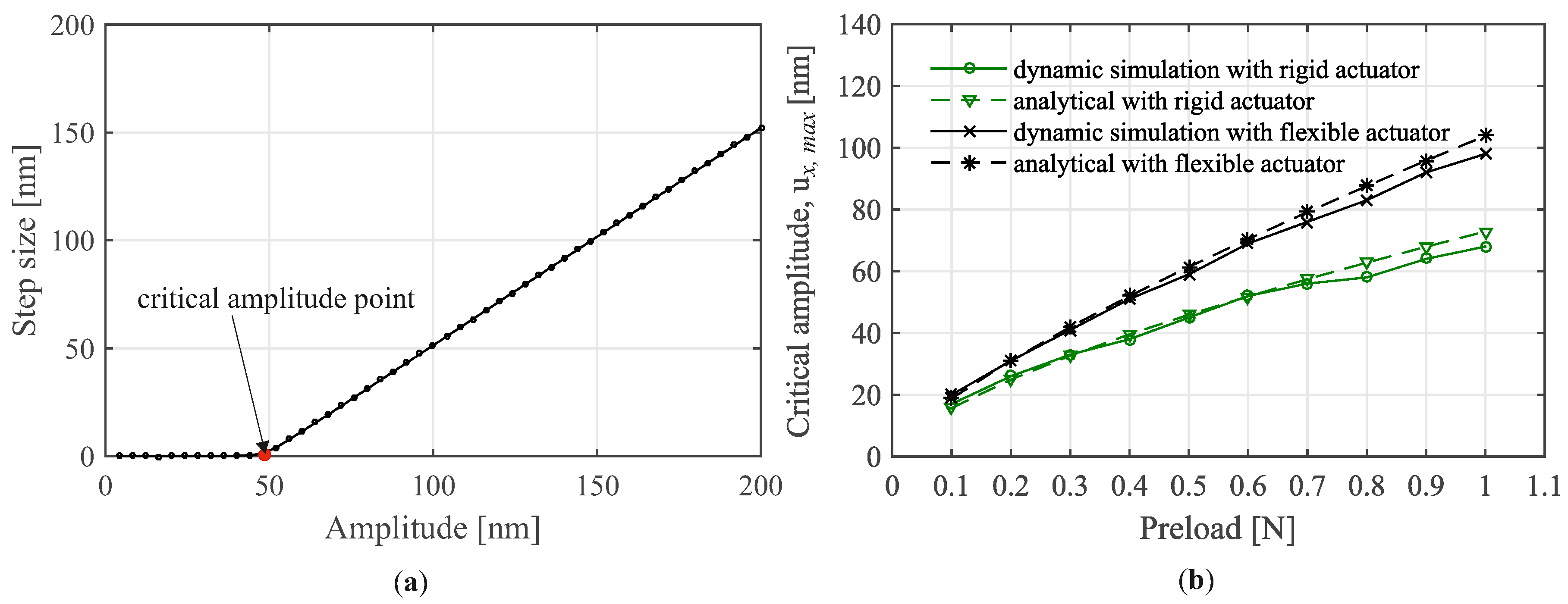
- The work of van der Wulp [5] is classified into the first group. In this work, the author explained that the critical amplitude is caused by the presliding, a maximal deformation of the guiding contacts before a full slip occurs, and the dynamic effects of the piezo actuators. The guiding contacts are described by the classical tangential contact theory. The piezo actuators are modeled as a mass–spring–damper system. However, only simple analytic formulations for critical amplitude were generated. Dynamic simulations were not implemented. Therefore, further investigation should be performed.
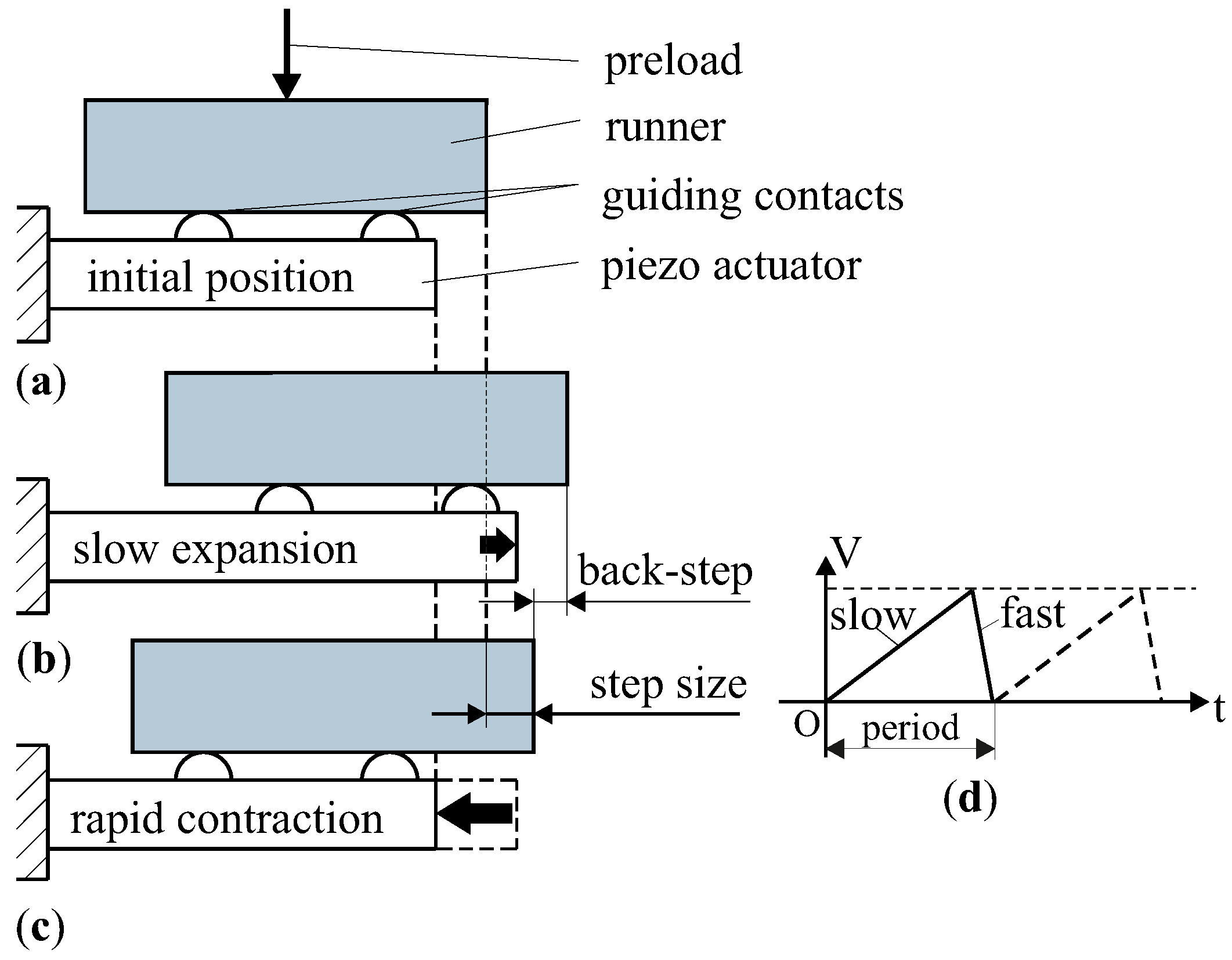
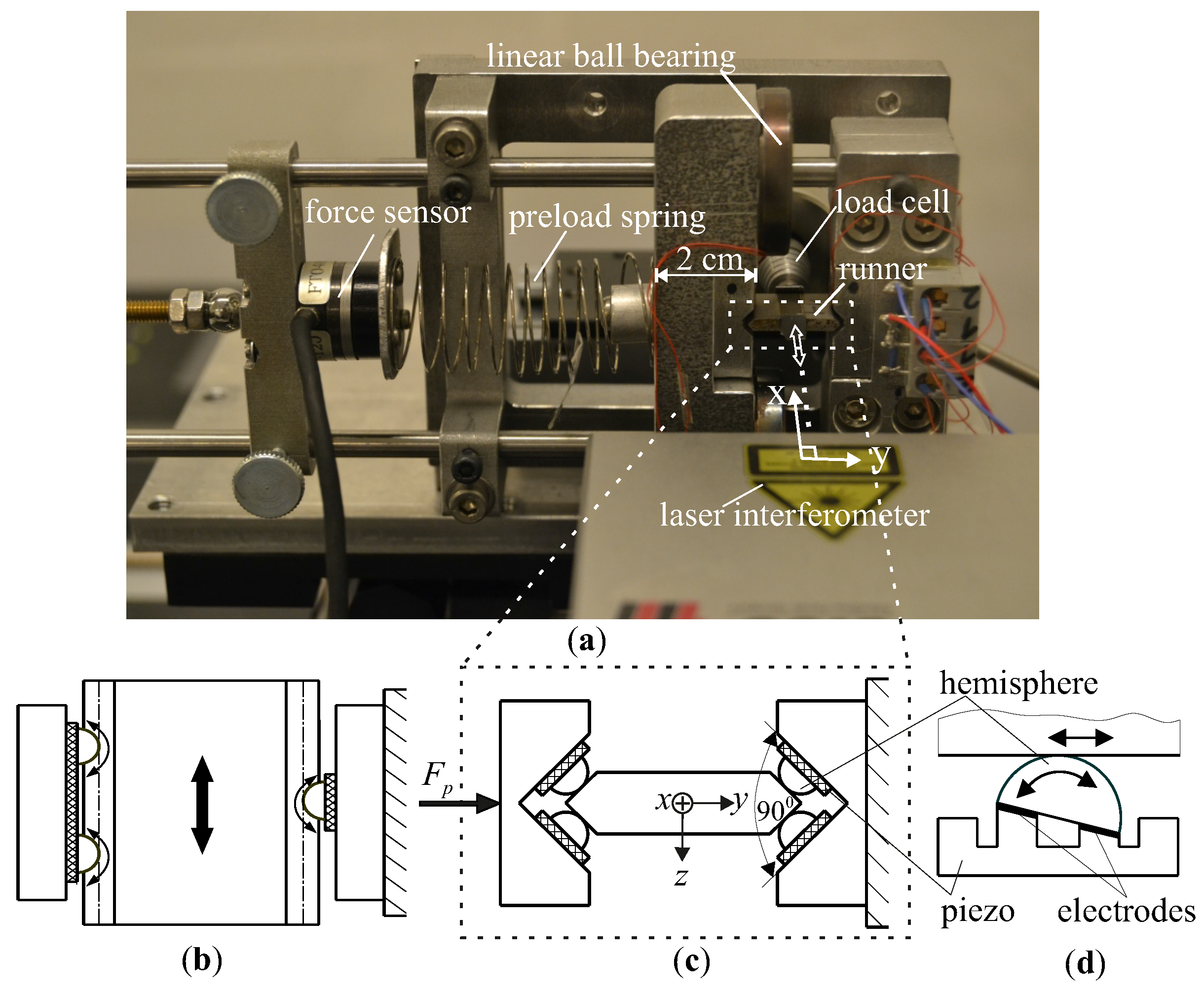
2. Investigated Drive
3. Modeling
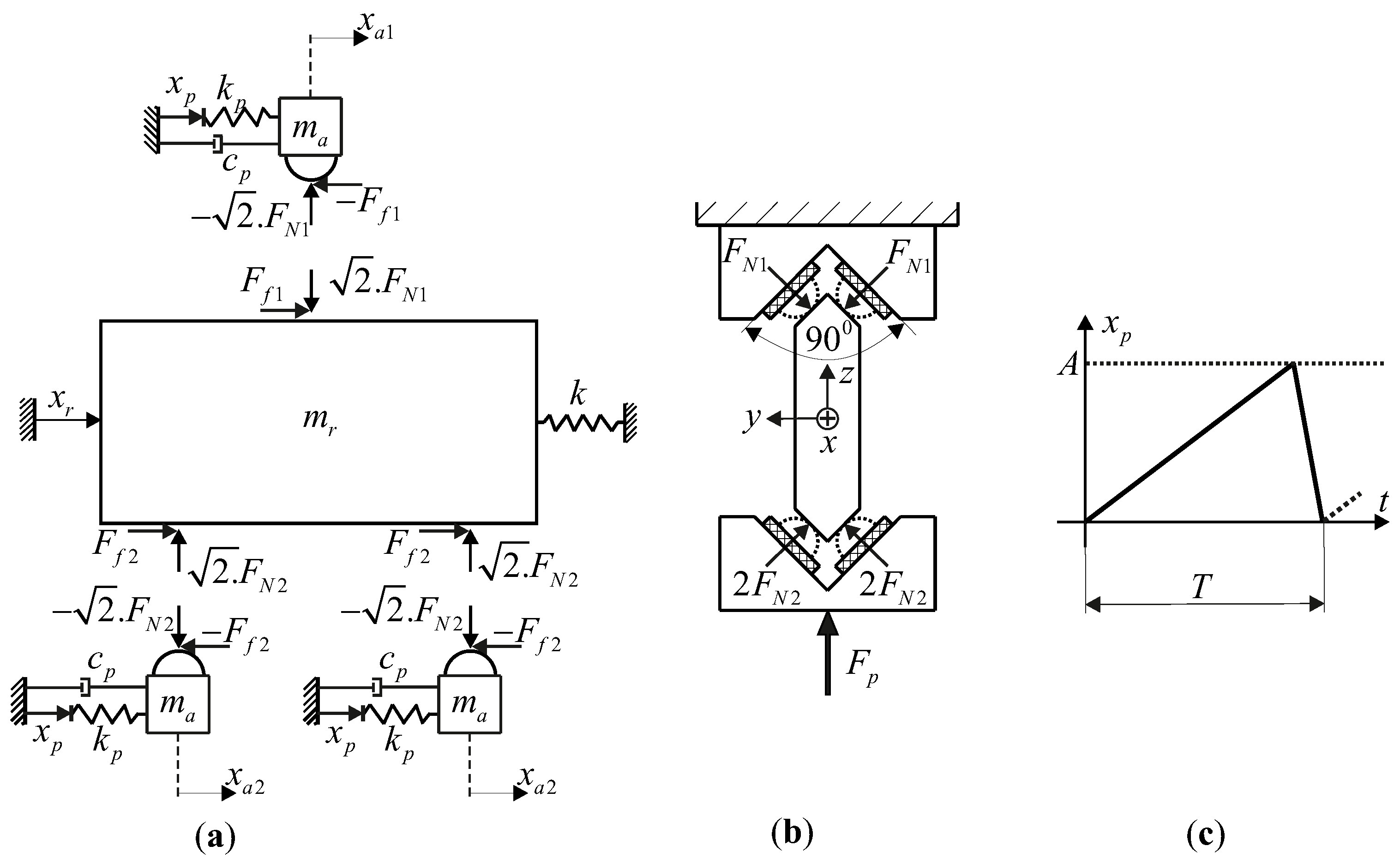
3.1. Macroscopic Modeling
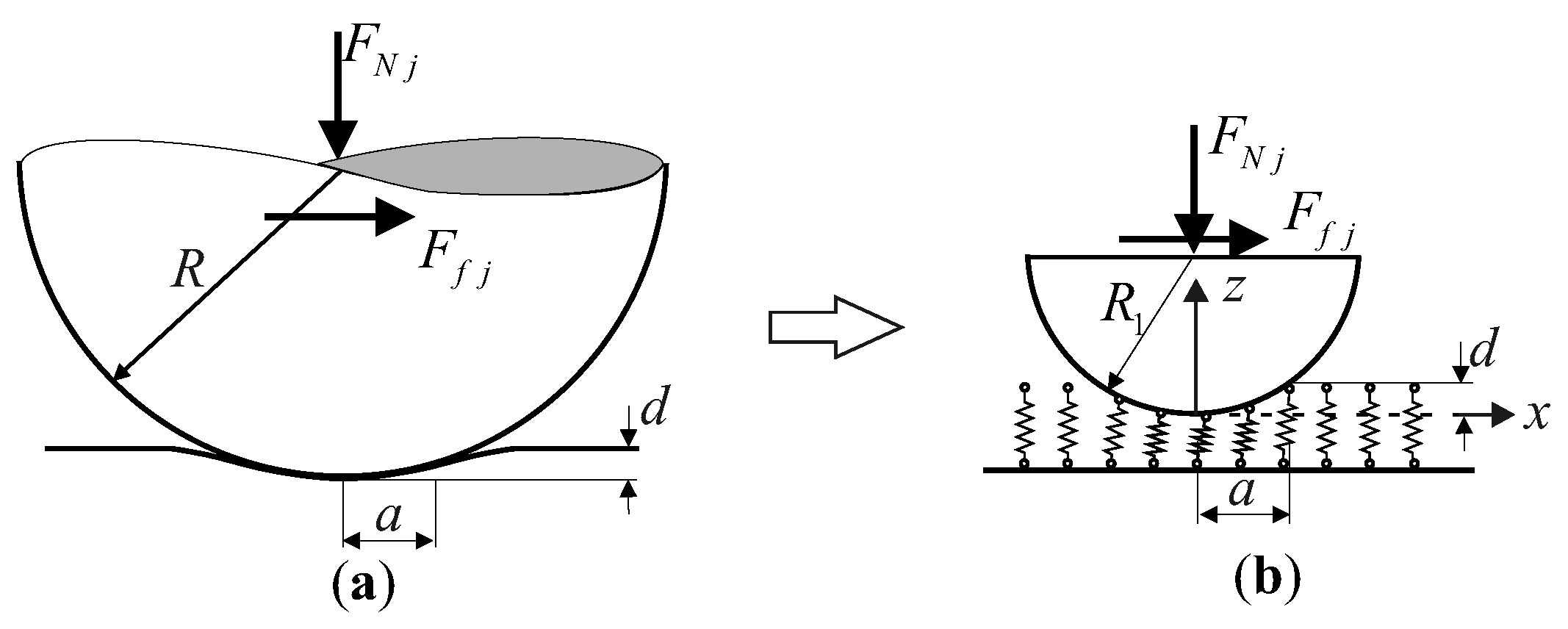
3.2. Microscopic Modeling
4. Validation
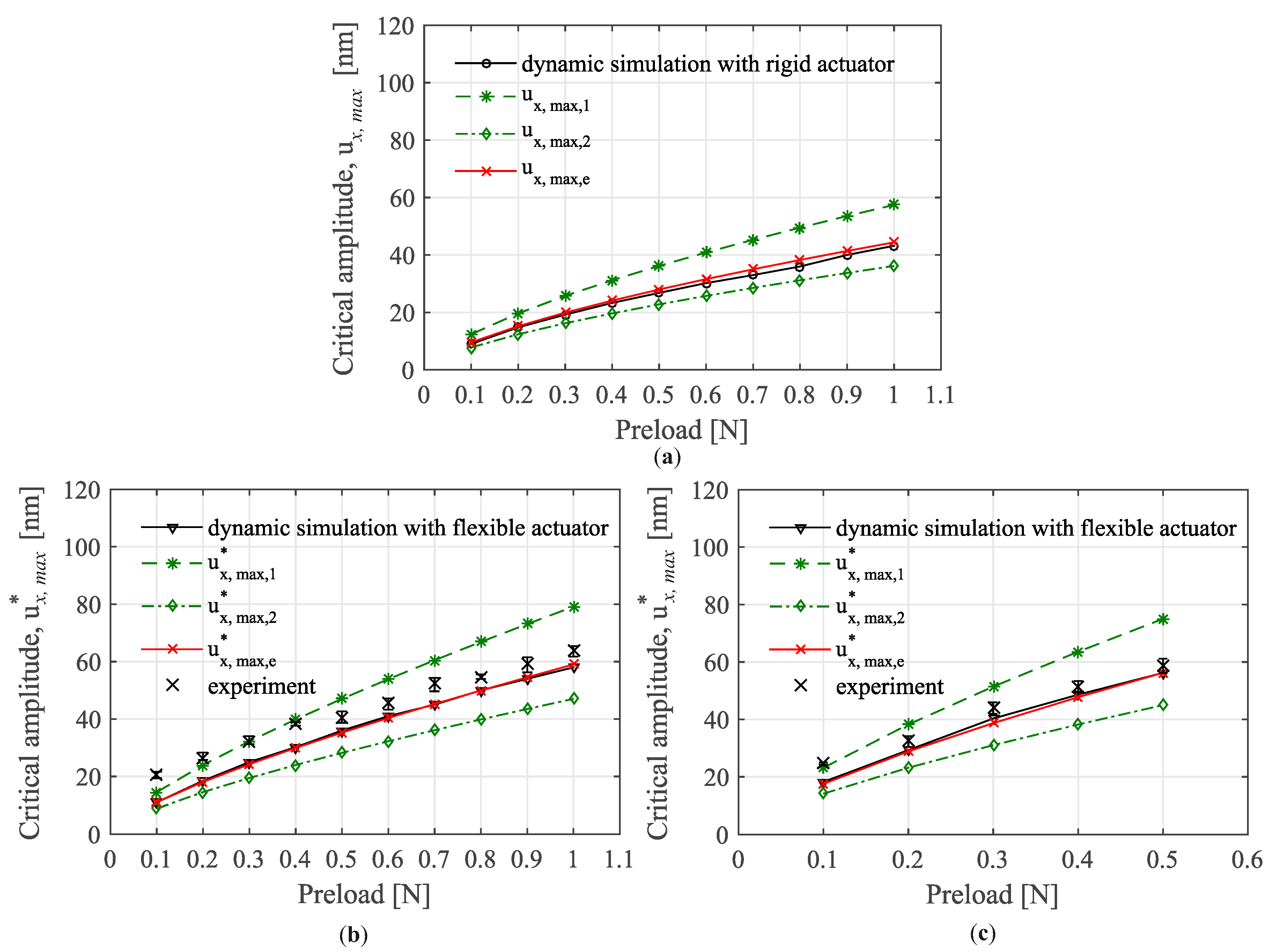
4.1. Critical Actuation Amplitude
4.1.1. One-Contact Model
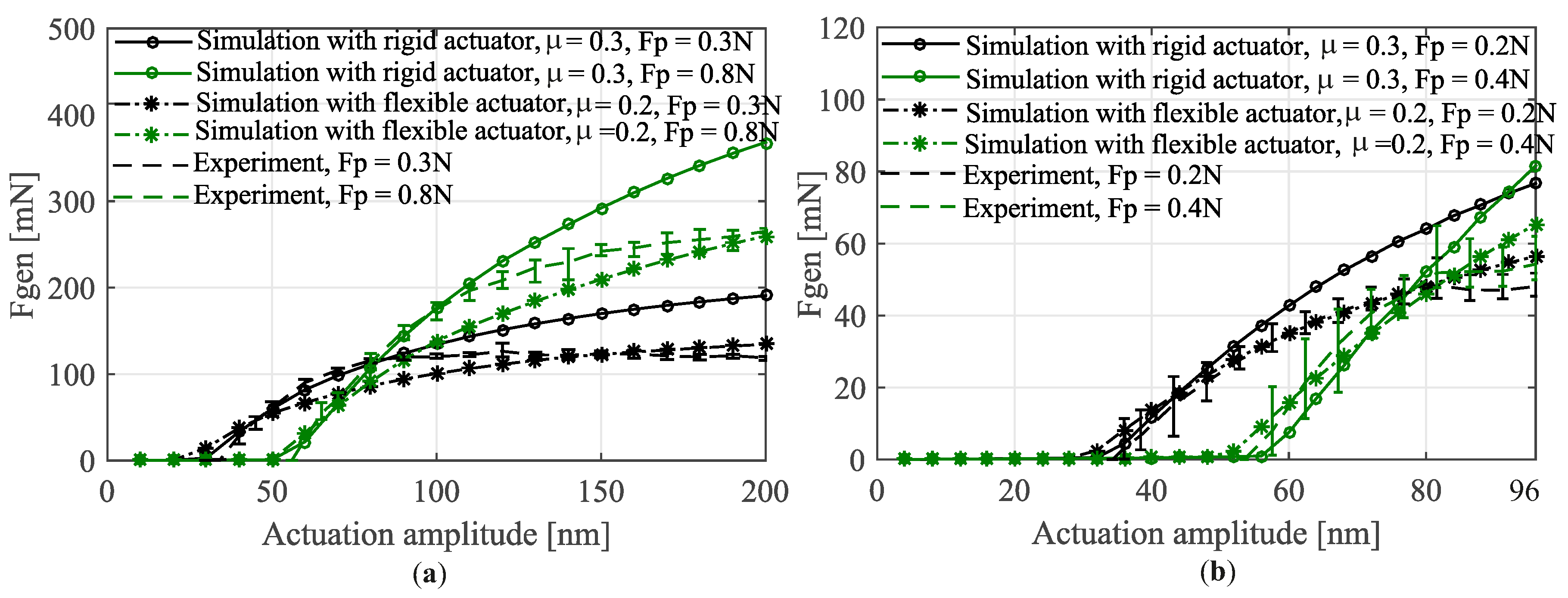
4.1.2. Six-Contact Model
4.2. Force Generation
5. Waveform Optimization
5.1. Theory
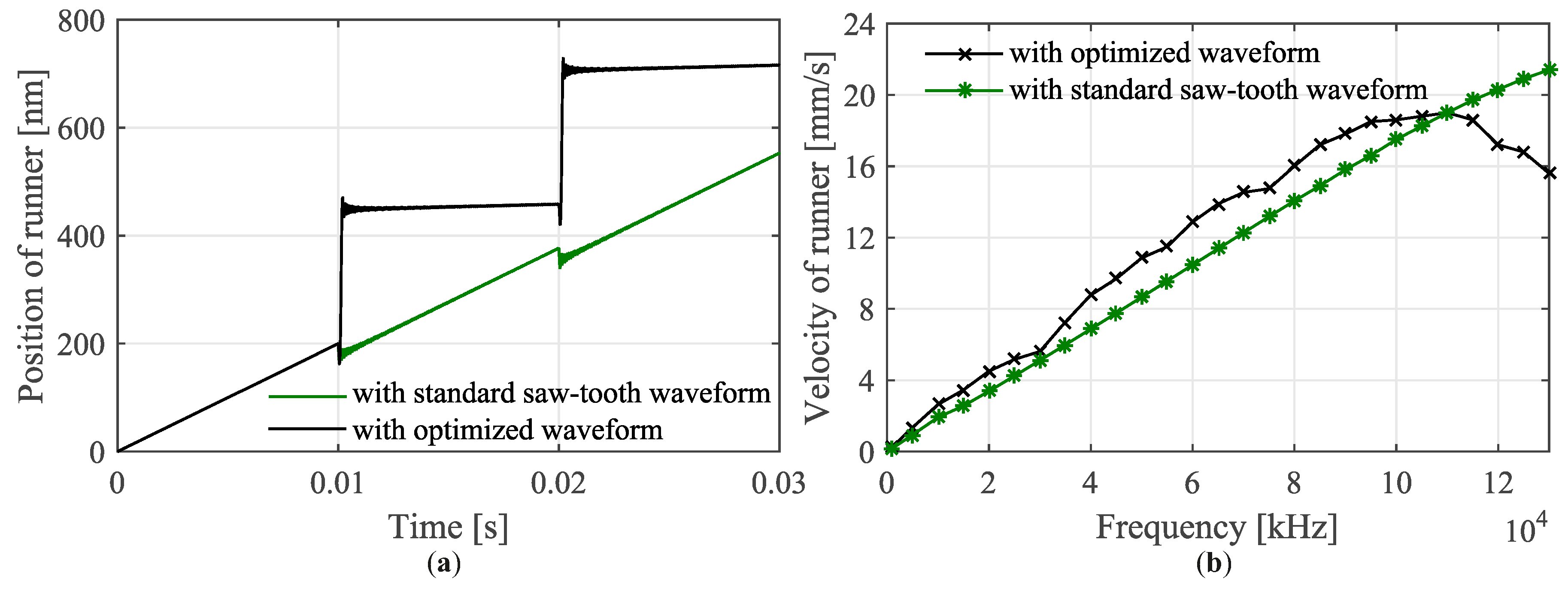
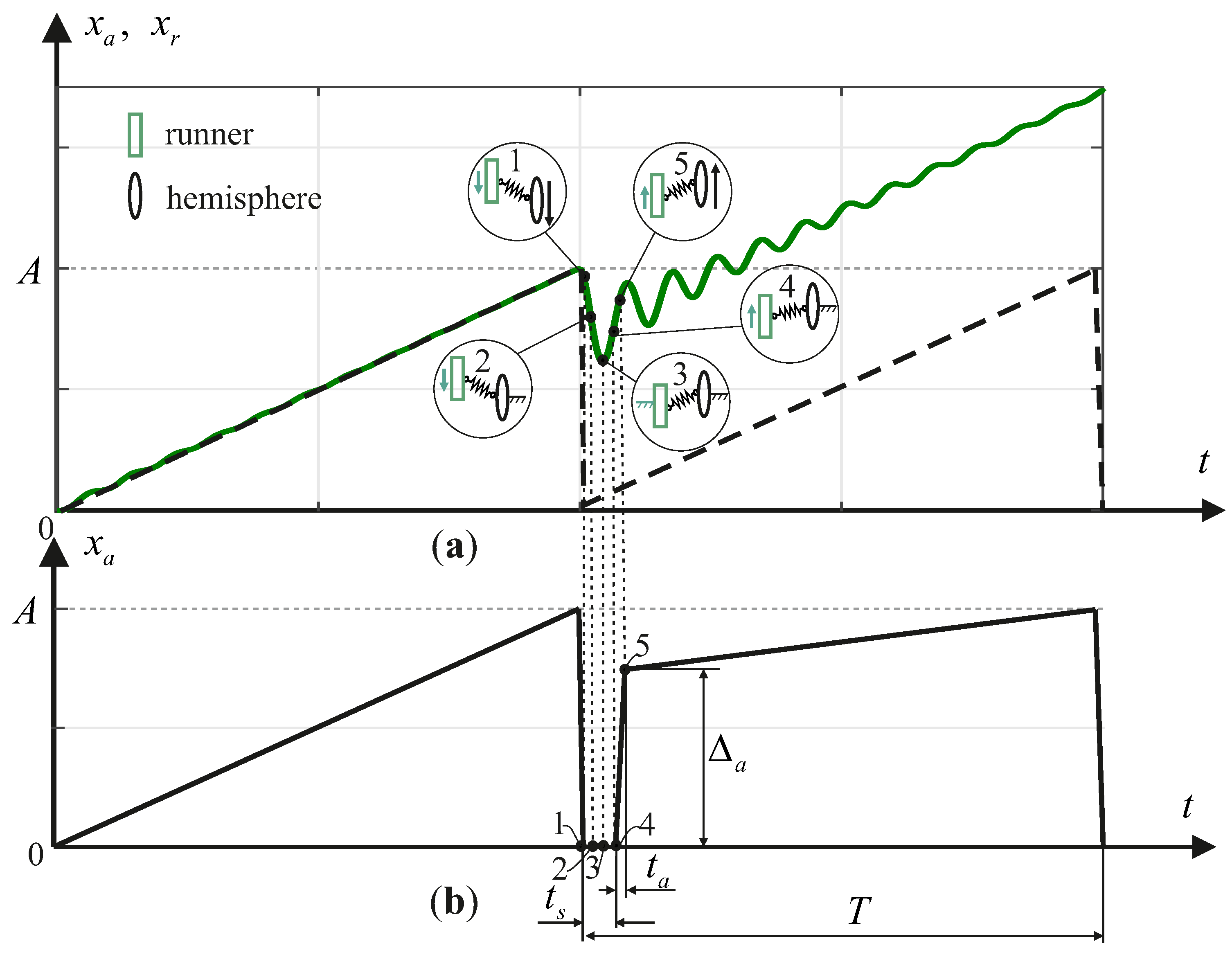
- Sub-phase I (settling and acceleration): After the stick-phase of the first period at point 1, the hemispheres are quickly displaced backward to the initial position. Because the runner cannot fully follow the displacement of the hemispheres, it performs a back-step and starts to vibrate. Consequently, the spring is deformed to a maximum, which is equal to the maximal tangential displacement of the contact . When the slip-phase is finished, instead of moving the hemispheres forward immediately as in the standard saw-tooth-like waveform, we make the hemispheres frozen with a settling time (see Figure 8b). The contact status within this time at points 2, 3 and 4 are depicted in the respective circles. At point 2, the runner moves backward, and at point 3, it starts to reverse the movement direction. At point 4, when the velocity of the runner is maximal, we displace the hemispheres quickly to point 5 with time and an amplitude . Because the runner and the hemispheres are moved in the same direction, the runner is accelerated with the hemispheres. In the acceleration process, if the velocity of the hemispheres is too large, a relative slip between the runner and the hemispheres will appear, similar to the slip-phase of the first period. Therefore, is chosen to satisfy that it has maximal magnitude and that the runner is still in the stick condition. The stick condition is ensured when , where u and are the relative displacement between the runner and hemispheres and the displacement of the runner, respectively.
- Sub-phase II (slip): At the end of the acceleration at point 5, the runner has the highest velocity, and thus the kinetic energy and the potential energy due to the deformation of the spring are maximal. We suddenly slow down the hemispheres. As a result, all the energy of the runner makes it quickly slip forward with a displacement that is sustainably larger than the displacement of the hemispheres. This leads to a larger step size for the runner in comparison with that of the standard saw-tooth-like driving waveform.
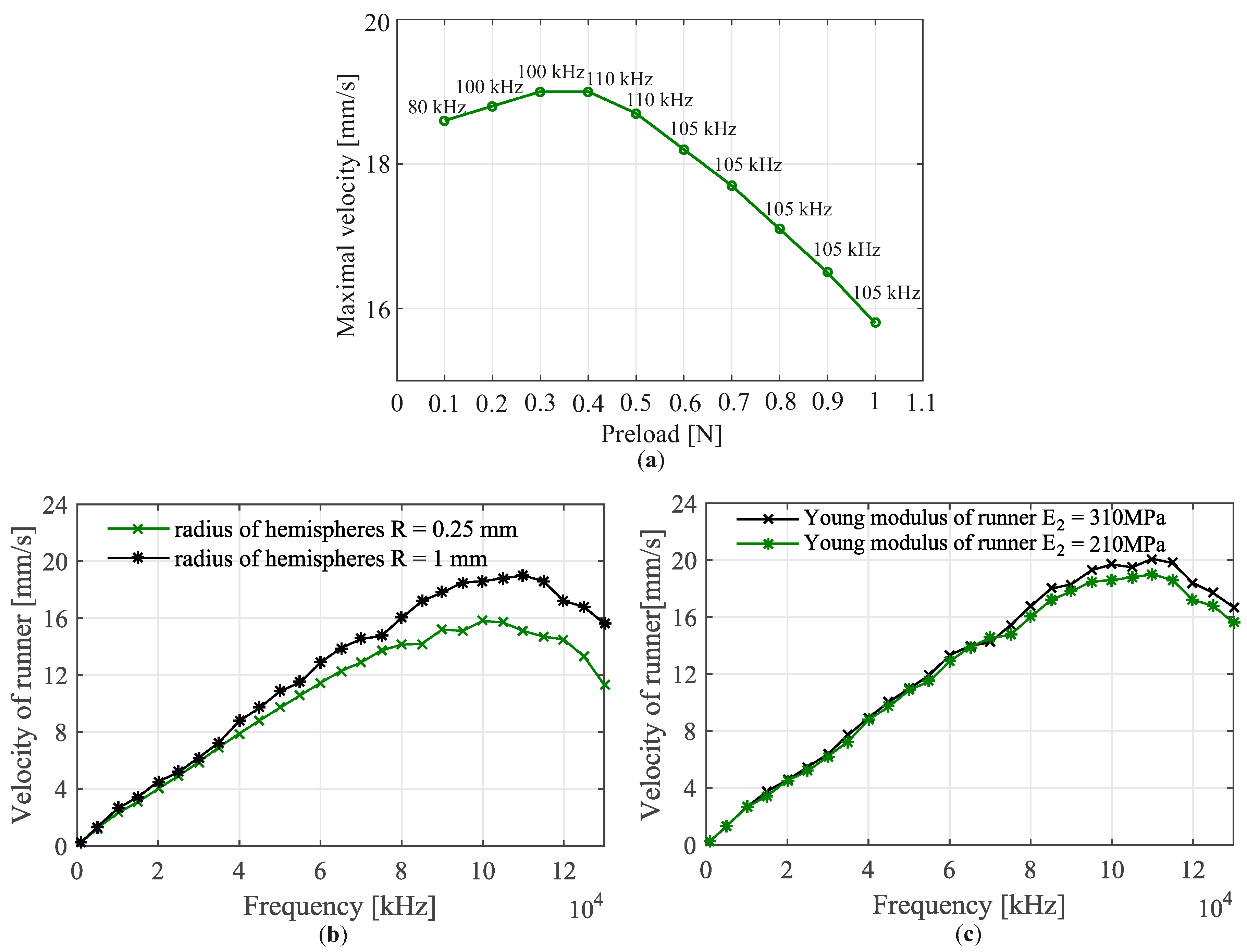
5.2. Results
6. Conclusions and Outlook
Acknowledgments
Author Contributions
Conflicts of Interest
References
- Eichhorn, V. Nanorobotic Handling and Characterization of Carbon Nanotubes inside the Scanning Electron Microscope. Ph.D. Thesis, Verlag Dr. Hut, München, Germany, 2011. [Google Scholar]
- Zhang, Z.M.; An, Q.; Li, J.W.; Zhang, W.J. Piezoelectric frictional inertia actuator: A critical review and future perspective. Int. J. Adv. Manuf. Technol. 2012, 62, 669–685. [Google Scholar] [CrossRef]
- Hunstig, M. Piezoelectric inertia motors—A critical review of history, concepts, design, applications, and perspectives. Actuators 2017, 6, 7. [Google Scholar] [CrossRef]
- Nguyen, X.H. Simulation, Validation and Optimization of Stick-Slip Drives for Nanorobotic Applications. Ph.D. Thesis, The University of Oldenburg, Oldenburg, Germany, 2014; pp. 13–16. [Google Scholar]
- Van der Wulp, H. Piezo-Driven Stages for Nanopositioning with Extreme Stability: Theoretical Aspects and Practical Design Considerations. Ph.D. Thesis, Delft University Press, Delft, The Netherlands, 1997. [Google Scholar]
- Hunstig, M.; Hemsel, T.; Sextro, W. Modelling the friction contact in an inertia motor. J. Intell. Mater. Syst. Struct. 2013, 24, 1380–1391. [Google Scholar] [CrossRef]
- Breguet, J.M. Stick and Slip Actuators. Ph.D. Thesis, Ecole Polytechnique Federale De Lausanne (EPFL), Lausanne, Switzerland, 1998. [Google Scholar]
- Peng, J.Y.; Chen, X.B. Modeling of piezoelectric-driven stick-slip actuators. IEEE/ASME Trans. Mechatron. 2011, 16, 394–399. [Google Scholar] [CrossRef]
- Edeler, C.; Meyer, I.; Fatikow, S. Modeling of stick-slip micro-drives. J. Micro-Nano Mechatron. 2011, 6, 65–87. [Google Scholar] [CrossRef]
- Edeler, C. Modellierung und Validierung der Krafterzeugung mit Stick-Slip-Antrieben fuer nanorobotische Anwendungen. Ph.D. Thesis, Verlag Dr. Hut, München, Germany, 2011. [Google Scholar]
- Teidelt, E.; Willert, E.; Filippov, A.E.; Popov, V.L. Modeling of the dynamic contact in stick-slip microdrives using the method of reduction of dimensionality. J. Phys. Mesomech. 2012, 15, 287–292. [Google Scholar] [CrossRef]
- Nguyen, H.X.; Teidelt, E.; Popov, V.L.; Fatikow, S. Modeling and waveform optimization of stick-slip microdrives using the method of dimensionality reduction. J. Arch. Appl. Mech. 2016, 86, 1771–1785. [Google Scholar] [CrossRef]
- Teidelt, E. Friction Induced Motion and Control of Friction. Ph.D. Thesis, Berlin University of Technology, Berlin, Germany, 2014. [Google Scholar]
- De Canudas, W.; Olsson, H.; Astrom, K.J.; Lischinsky, P. A new model for control of systems with friction. IEEE Trans. Autom. Control 1995, 40, 419–425. [Google Scholar] [CrossRef]
- Dupont, P.; Hayward, V.; Armstrong, B.; Altpeter, F. Single state elastoplastic friction models. IEEE Trans. Autom. Control 2002, 47, 787–792. [Google Scholar] [CrossRef]
- Dahl, P.R. A Solid Friction Model; Aerospace Corp: El Segundo, CA, USA, 1986. [Google Scholar]
- Popov, V.L. Basic ideas and applications of the method of reduction of dimensionality in contact mechanics. J. Phys. Mesomech. 2012, 15, 254–263. [Google Scholar] [CrossRef]
- Popov, V.L. Method of reduction of dimensionality in contact and friction mechanics: A linkage between micro and macro scales. Friction 2013, 1, 41–62. [Google Scholar] [CrossRef]
- Špiller, M.; Hurák, Z. Hybrid charge control for stick-slip piezoelectric actuators. J. Mechatron. 2011, 21, 100–108. [Google Scholar] [CrossRef]
- Bergander, A.; Breguet, J.M. Performance improvements for stick-slip positioners. Proc. Int. Symp. Micromechatron. Hum. Sci. 2003. [Google Scholar] [CrossRef]
- Hunstig, M.; Hemsel, T.; Sextro, W. Stick-slip and slip-slip operation of piezoelectric inertia drives—Part I: Idea excitation. Sens. Actuators A Phys. 2013, 200, 90–100. [Google Scholar] [CrossRef]
- Hunstig, M.; Hemsel, T.; Sextro, W. High-velocity operation of piezoelectric inertia motors: Experimental validation. Arch. Appl. Mech. 2016, 86, 1733–1741. [Google Scholar] [CrossRef]
- Teidelt, E.; Nguyen, X.H.; Fatikow, S.; Popov, V.L. Numerische simulation von nano-stick-slip positionierungsantrieben mittels der methode der dimensionsreduktion. In Proceedings of the Tribologie-Fachtagung, Göttingen, Germany, 30 September–2 October 2013. [Google Scholar]
- Lübke, M. Aufbau Eines Reibkraftmessstandes und Durchführung von Messreihen; Universität Oldenburg: Oldenburg, Germany, 2010. (In German) [Google Scholar]


| Young’s Modulus (GPa) | Poisson’s Ratio | Friction Coefficient | Mass of Runner (g) | Stiffness of Load Cell (N/m) | Radius of Hemisphere (mm) |
|---|---|---|---|---|---|
| (ruby) | |||||
| (steel) | — | — | — | — |
| Stiffness of Actuator (N/m) | Viscosity Factor (kg/s) | Mass of Actuator (g) | Preload Range with Step 0.1 N (N) | Actuation Amplitude Range (nm) | |
|---|---|---|---|---|---|
| 0.1–0.5 | 0–96 | ||||
| –1 | 0–202 |
© 2018 by the authors. Licensee MDPI, Basel, Switzerland. This article is an open access article distributed under the terms and conditions of the Creative Commons Attribution (CC BY) license (http://creativecommons.org/licenses/by/4.0/).
Share and Cite
Nguyen, X.-H.; Mau, T.-H.; Meyer, I.; Dang, B.-L.; Pham, H.-P. Improvements of Piezo-Actuated Stick–Slip Micro-Drives: Modeling and Driving Waveform. Coatings 2018, 8, 62. https://doi.org/10.3390/coatings8020062
Nguyen X-H, Mau T-H, Meyer I, Dang B-L, Pham H-P. Improvements of Piezo-Actuated Stick–Slip Micro-Drives: Modeling and Driving Waveform. Coatings. 2018; 8(2):62. https://doi.org/10.3390/coatings8020062
Chicago/Turabian StyleNguyen, Xuan-Ha, Tien-Hiep Mau, Ingo Meyer, Bao-Lam Dang, and Hong-Phuc Pham. 2018. "Improvements of Piezo-Actuated Stick–Slip Micro-Drives: Modeling and Driving Waveform" Coatings 8, no. 2: 62. https://doi.org/10.3390/coatings8020062
APA StyleNguyen, X.-H., Mau, T.-H., Meyer, I., Dang, B.-L., & Pham, H.-P. (2018). Improvements of Piezo-Actuated Stick–Slip Micro-Drives: Modeling and Driving Waveform. Coatings, 8(2), 62. https://doi.org/10.3390/coatings8020062