Article

Porous ZnO/2–Hydroxyethyl Methacrylate Eluting Coatings for Ureteral Stent Applications

1
Department of Applied Science and Technology, Politecnico di Torino, Corso Duca degli Abruzzi, 24, 10129 Torino, Italy
2
Department of Polymer Chemistry, Maria Curie Sklodowska University, Gliniana 33, 20-614 Lublin, Poland
*
Author to whom correspondence should be addressed.
Coatings 2018, 8(11), 376; https://doi.org/10.3390/coatings8110376
Submission received: 14 September 2018 / Revised: 9 October 2018 / Accepted: 22 October 2018 / Published: 23 October 2018

Abstract

:
High-surface-area porous coatings represent an interesting option to fabricate eluting stents with additional functionalities, as controlled drug delivery and antibacterial resistance properties. ZnO is a biocompatible material available in various high-surface-area morphologies, with promising antibacterial properties. Hydrophilic 2-hydroxyethyl methacrylate (HEMA) polymers (pHEMA) have been widely investigated for their biomedical applications, thanks to their biocompatibility, absence of toxicity, and tunable swelling properties. This work aims to demonstrate the use of porous ZnO/polymer bilayer coatings for future drug eluting stent applications. Sputtered mesoporous ZnO layers were coated with pHEMA and p(HEMA-co-acrylic acid (AA)) films through vacuum infiltration and drop-casting methods. The last approach was found to be the most suitable one for achieving a good polymer infiltration within the ZnO matrix and to avoid the mechanical detachment of the porous film from the substrate. The corresponding release properties were evaluated by loading a fluorescent dye in the host ZnO matrix, before drop-casting the polymer coating. For pure ZnO, the release of the dye was completed after 2 h. For ZnO/pHEMA, the sustained release of the molecule was achieved with only 30% released after 2 h and 100% released after seven days. In this case, the pH-triggered delivery properties were also demonstrated by switching from neutral to acidic pH conditions. No significant changes were obtained for the ZnO/p(HEMA-co-AA) system, which exhibited a faster swelling behavior and a release profile similar to pure ZnO.

1. Introduction

High-surface-area porous coatings for implantable biomedical devices represent an intriguing solution to confer the device additional functionalities with respect to the uncoated implant [1]. In this regard, drug-releasing devices featuring biocompatibility, biostability, antibacterial resistance properties, efficient drug loading and delivery should be pursued. For such purposes, the most commonly used materials are polymers [2]; new generation carbon-based materials, such as graphene and graphene oxide [3]; and other inorganic porous materials like anodized alumina [4], titania nanotubes [5], and porous silicon coatings [6]. However, most of these are limited by their unpredictable rather than poor degradation behaviors, also resulting in toxic reaction products in some cases, thereby inducing undesirable inflammatory reactions in the body.
Nowadays, one of the main limitation affecting ureteral stents’ operation is the formation of progressive encrustations due to inorganic salt deposition and bacteria biofilm formation, resulting in the total occlusion of the stent lumen in the worst case, especially for prolonged indwelling times. Therefore, new practical solutions are strongly required to face the above-mentioned critical issues, that is, to fight the infections rising in patients because of bacteria biofilm formation and to guarantee a suitable urine drainage, finally avoiding the stent exchange at regular intervals. Within this scope, some solutions have been developed so far, and which have mostly involved the surface modification of the stent by the deposition of functional coatings such as antimicrobial silver [7], hydrophilic coating with hydrogel (like Hydromer®) [8], heparin [9], plasma-deposited diamond-like amorphous carbon coatings [10], and many more. With these solutions, both the bacterial adhesion and the formation of inorganic encrustation have been limited to some extent. To further improve and intelligently render the ureteral stent performances, however, drug eluting capabilities [11,12,13] and the complete biodegradation [14] of the stent materials would be required. Presently, only some efforts in this direction are in place, with some satisfactory results in animal models using polylactic acid (PLA) polymers [15]. However, the incomplete dissolution of the stent, leading to the permanence in the ureter to small polymer fragments [16], causing an obstruction to the urine flow that is then impossible to be further removed without surgical intervention. Concerning drug eluting stents, some antibiotics, like triclosan, have not received approval from the Food and Drug Administration (FDA) because of their potential for developing antibiotic resistance [17]. Thus, in this prospect, the use of intrinsically antimicrobial materials (i.e., nanoantibiotics) [18,19] with a nanostructured surface able also to host therapeutic molecules will be of great interest.
Zinc oxide (ZnO) is attracting increasing interest for a wide plethora of application fields, including the biomedical one [20,21], in particular as an antibacterial agent [22]. ZnO is a wide band-gap metal oxide n-type semiconductor, showing a generous surface chemistry, interesting optical and piezoelectric properties, and promising photocatalytic activities at the same time. It has been successfully explored for new-generation energy harvesting systems [23], sensors [24], and photocatalytic systems [25]. Moreover, ZnO in the bulk form has already been considered as safe and has been approved by the FDA [26]. More interestingly, various ZnO morphologies and shapes showing high-surface areas and porous structures coupled with a generous surface chemistry may be easily prepared and functionalized [27]. Some examples include porous thin films [28], nanowires [29], nanocrystals [30], and flower-like structures [31], which are easily obtainable by following numerous dry and wet synthetic approaches, like sol–gel strategies, hydrothermal routes, and vapor-phase deposition methods.
At first, the investigation of ZnO nanomaterials for biomedical applications was highly focused on their use in the fabrication of biosensing units [32] able to detect various bio moieties, like proteins, glucose, and acid uric. More recently, ZnO nanomaterials have been successfully explored for tissue engineering [33], drug-delivery [34], and anticancer therapeutics [35] as well. The active promotion of cell growth and proliferation, together with its proangiogenic, osteogenic, and antibacterial properties, have been reported [36], and the efficacy of ZnO in promoting wound healing and the formation of new bone tissue has been successfully demonstrated. High-surface area ZnO morphologies have been investigated for drug delivery applications as well [34]. For this purpose, the high sensitivity of ZnO against pH variations was successfully exploited and for different ZnO nanostructures, which exhibited pH-triggered release properties for various drug molecules. Moreover, ZnO can be successfully used in photodynamic therapy, thanks to its reactive oxygen species (ROS) generation properties under UV irradiation in aqueous media [35]. Finally, the combination of a broad visible emission spectrum, strong luminescence, and the ability to generate ROS and work as a drug delivery system, also make ZnO nanostructures promising candidates for theranostic platforms with both imaging and therapeutically-active properties.
Hydrophilic 2-hydroxyethyl methacrylate polymers (pHEMA) are widely used in biomedical applications because of their biodegradability and biocompatibility [37]. Moreover, tunable swelling behaviors can be easily obtained with the addition of specific monomers like acrylic acid [38,39]. Several works demonstrated the successful use of pHEMA as drug delivery systems [40] in ophthalmology [41] and in plastic surgery.
In this work, the combination of the above-mentioned properties of porous ZnO, that is, its drug delivery, biodegradation, and prospective anti-microbial effects, were combined with a soft biodegradable polymeric matrix intended as a smart coating for ureteral stents. In particular, mesoporous ZnO coatings were obtained by a facile two-step synthetic approach, combining the sputtering technique and thermal oxidation. The corresponding molecule loading and release properties were evaluated by considering calcein (i.e., a fluorescent dye) as a model drug molecule. The as-prepared ZnO films exhibited interesting molecule loading capacities because of their high surface area and generous surface chemistry, but they also displayed fast and uncontrolled release kinetics. To overcome this limitation, biocompatible 2-hydroxyethyl methacrylate (pHEMA) and p(HEMA-co-acrylic acid (AA)) polymer coatings were deposited by vacuum infiltration and drop-casting techniques, atop of the calcein-loaded mesoporous ZnO matrix. The release behavior of the resulting ZnO/pHEMA and ZnO/p(HEMA-co-AA) bilayer structures was evaluated in vitro, and the effect of switching the pH conditions from neutral to slightly acidic on the release properties was evaluated.

2. Materials and Methods

2.1. Preparation of Porous ZnO Thin Films

Porous ZnO thin films were prepared by following a two-step synthetic approach [34], involving the deposition of metallic Zn films by sputtering, and a thermal oxidation process. In the first step, porous Zn layers were deposited at room temperature on silicon (Si; 100-oriented; p-type) substrates (~1 cm2 area) by radio-frequency (RF, 13.56 MHz) magnetron sputtering (from Elettrorava, Venaria, Italy; see Figure S1 of Supporting Information (SI) for further details on sputtering machine geometry). Si was selected as a reference substrate material because of its smooth and flat surface, and the absence of any porosity, thus avoiding any artifact during the loading and release experiments. Moreover, it facilitates the preparation of samples for cross-section imaging, because it can be easily cut along a specific crystallographic direction. Zn depositions were carried out starting from a four-inch diameter metallic Zn target, in a pure Ar atmosphere, with a fixed deposition pressure of 5 × 10⁻³ Torr, and a RF power density of 0.66 W·cm−2. The overall deposition time was set to 4 h and the final average thickness of the Zn layer was 10 μm. After the deposition, the Zn/Si samples were thermally oxidized in a muffle furnace (L-401K2RN from Nabertherm™, Lilienthal, Germany) at 380 °C (ramp rate 150 °C/h), in air for 2 h. Before starting the Zn deposition, the Si substrates were properly cleaned in an ultrasonic bath of acetone and ethanol (10 min for each washing cycle), and were dried under a nitrogen flow (99.999% purity).

2.2. Preparation of PolyHEMA (pHEMA) and Poly(HEMA-co-AA)

2-hydroxyethyl methacrylate (HEMA, 99%), acrylic acid (AA), and 2,2′-azobis(2-methylpropionitrile) (AIBN, 98%) were obtained from Sigma-Aldrich (Darmstadt, Germany). Ethanol and methanol were from POCh (Gliwice, Poland). The monomers (HEMA and AA) were purified from inhibitors using vacuum distillation, and were stored in a refrigerator until use. The other reagents were used as received, without further purification. The synthesis of the homopolymer (pHEMA) and copolymer p(HEMA-co-AA) was performed with the use of radical polymerization in the toluene solution. The appropriate amounts of monomer HEMA or mixture of HEMA and AA (2.75:1 molar mixture) were mixed with the initiator, AIBN (2 wt %). The polymerization reaction was carried out under a nitrogen atmosphere at 70 °C for 8 h. After the completion of the polymerization, the obtained polymers were filtered and dried under a vacuum. The weight-average molar mass (Mw) and molar-mass dispersity (PDI), determined by the gel permeation chromatography (GPC) method were as follows: 12,500 Da and 1.41 for pHEMA, respectively, and 8500 Da and 1.35 for p(HEMA-co-AA) respectively.

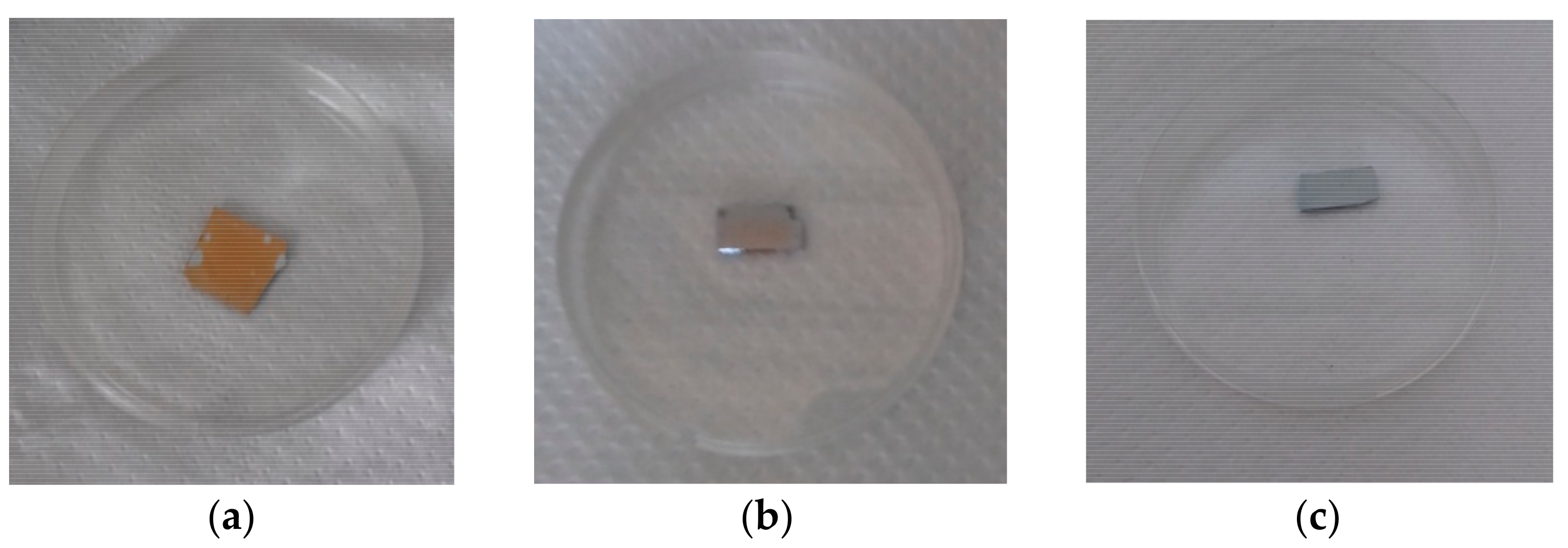
2.3. Preparation of ZnO/Polymer Bilayer Coatings

The pHEMA and p(HEMA-co-AA) polymer solutions (10 wt %) were prepared by mixing each polymer (396 mg) in methanol (5 mL), under magnetic stirring at room temperature. The pHEMA and p(HEMA-co-AA) films were obtained starting from the as-prepared solutions, by following two separate deposition approaches: (i) vacuum infiltration and (ii) drop-casting technique. In the first case, the ZnO/Si samples were placed at the bottom of a glass round-bottom flask connected to a rotary pump for creating low vacuum conditions. Then, 100 μL of the polymer solution was injected inside the reactor using a syringe through a rubber septum, and was left in static vacuum pumping conditions for 30 min. Then, the vacuum was set for an additional 30 min to promote solvent evaporation and the stabilization of the polymer film. A schematic representation of the apparatus used for vacuum infiltration is shown in Figure S2 of SI. In the second approach, the polymer solution (100 μL) was drop-casted directly atop the porous ZnO surface. Then, the solvent evaporation was obtained by drying the samples overnight at room temperature.

2.4. Calcein Loading and Release Experiments

The loading experiments were performed in simulated body fluid (SBF; pH 7.4), prepared according to Kokubo’s protocol [42]. Then, 9.34 mg of fluorescent calcein dye (Carl Roth, 622.55 molar mass) was dissolved in 15 mL SBF, at room temperature, under continuous stirring (200 rpm) for 30 min. The calcein was loaded by soaking the porous ZnO/Si samples for 2 h in 2 mL of the loading solution (1 × 10⁻³ M), in orbital shaking conditions (200 rpm) at room temperature. After the calcein loading, all of the samples were stored in the dark and were air-dried overnight. Then, each sample was diced in two equal parts (each one with dimension of ~0.5 cm2). The release experiments were carried out in duplicate, by soaking the samples in 5 mL of the release solution, that is, SBF or 5.8-buffered solution, in orbital conditions (200 rpm) at 37 °C. Then, 100 μL of aliquot was collected from each release solution at specific points of time (5 min, 15 min, 30 min, 60 min, 120 min, 24 h, 48 h, 72 h, and 7 days), and analyzed using UV-Vis spectroscopy. The molecule release profile was then constructed by considering the characteristic calcein UV absorbance peak at 473 nm. This was compared with a calibration curve obtained by evaluating the UV absorbance value at 473 nm for a series of calcein dilutions (from 1 × 10⁻⁶ M to 1 × 10⁻³ M), prepared both in the SBF and pH 5.8 buffered solutions. The amount of calcein at each release time and the corresponding cumulative release profiles were obtained according to the literature [34]. All of the loading and release experiments were performed in dark conditions so as to prevent any degradation of the fluorescent dye.

2.5. Characterization Setup

The attenuated total reflectance (ATR)-FTIR spectra of the polymers were recorded using the Tensor 27 spectrometer (Bruker, Bremen, Germany), equipped with a diamond crystal. The spectrum was made in the spectral range of 4000–600 cm−1, with a resolution of 4 cm−1, and with 16 scans per spectrum. The weight-average molar mass (Mw) and the molar-mass dispersity (PDI) of the polymer and copolymer samples were determined using the gel permeation chromatography (GPC) method, with the use of Shimadzu LC-20AD liquid chromatograph equipped with an ELSD (Evaporative Light Scattering Detector) detector (Shimadzu Kyoto Corporation, Kyoto, Japan), using two Phenogel columns (pore sizes of 100 Å and 50 Å in series) and THF (tetrahydrofuran) as eluent with a flow rate of 1 mL min−1 at 35 °C. Monodistributed poly(methyl methacrylate) was used as the calibration standards. Before the analyses, the studied polymers were dissolved in methanol/acetonitrile (50/50 v/v). The 1H NMR spectra were obtained using a Bruker Avance 300 MSL spectrometer (Bruker, Bremen, Germany) at the field strength of 300 MHz. The polymer solutions were prepared in deuterated methanol. The morphology of the samples was evaluated by means of a field-emission scanning electron microscope (FESEM, Merlin Carl Zeiss AG, Oberkochen, Germany). The ATR-FTIR spectra of the ZnO/polymer samples were acquired with a 4 cm−1 resolution and 16 scans per spectrum were accumulated, using a Nicolet 5700 FTIR Spectrometer (ThermoFisher, Waltham, MA, USA), and were background subtracted. The UV-VIS absorbance spectra were collected in the range of 200–800 nm, by means of a microplate reader (Multiskan™ FC Microplate Photometer, from ThermoFisher Scientific, Waltham, MA, USA). All of the UV spectra were background subtracted.

3. Results and Discussion

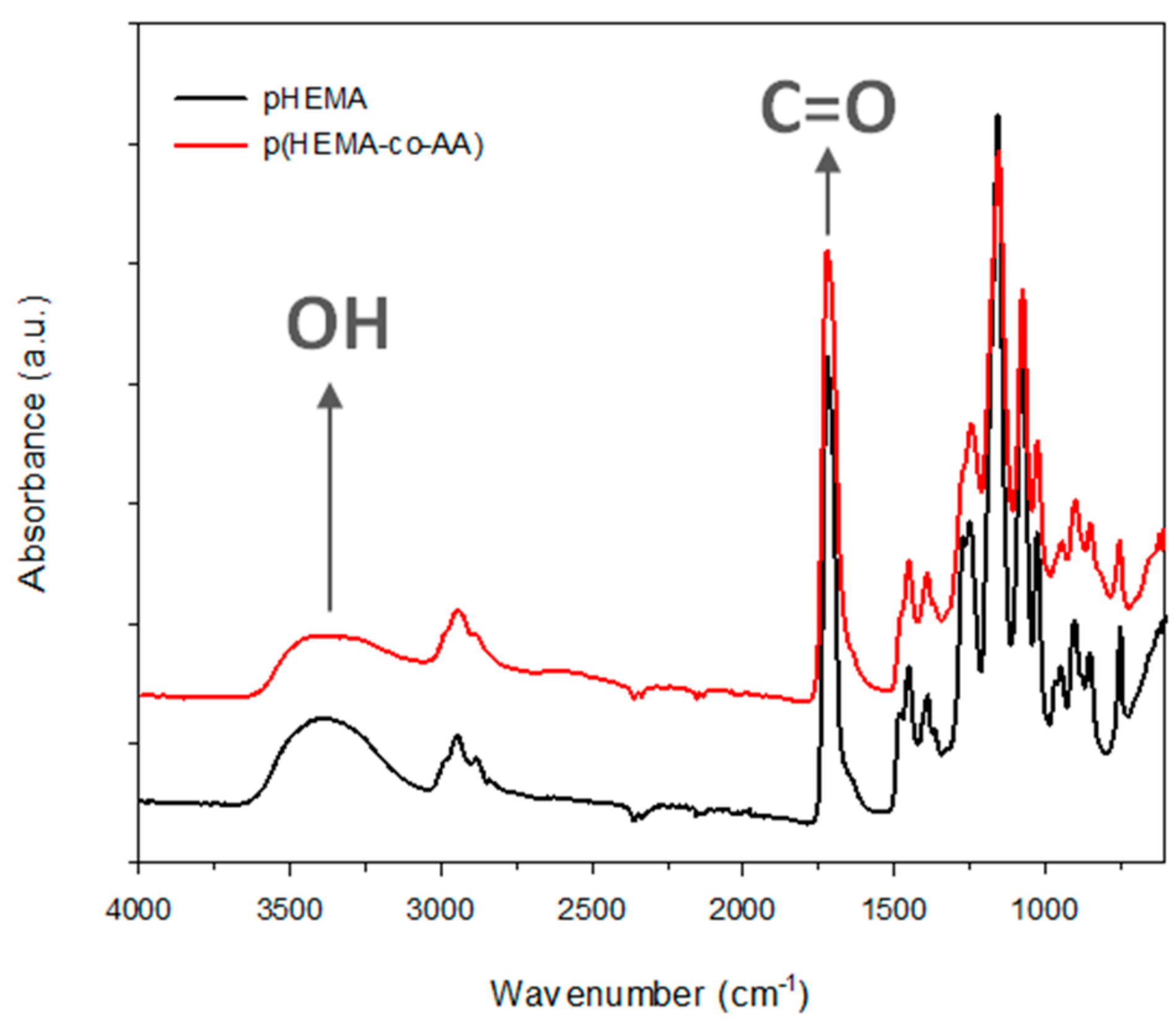
3.1. Characterization of PolyHEMA (pHEMA) and Poly(HEMA-co-AA)

The FTIR spectra of the homopolymer pHEMA and copolymer p(HEMA-co-AA) are presented in Figure 1. It is apparent that both the spectra contain similar peaks because of the similar structure of the monomers used for the synthesis of the polymers. For the pure pHEMA, the absorption band derived from the hydroxyl group vibration is observed at 3400 cm−1. The sharp absorption band at 1721 cm−1 corresponds to the carbonyl group (C=O) vibration. In the spectrum of the copolymer, the absorption band centered at 1720 cm−1 is also derived from the vibrations of the C=O group from HEMA, as well as from the associated carboxylic acid group. The position of the carbonyl group peak vibration suggests that most of the carboxylic acid groups are associated with the intermolecular hydrogen bonds formed between the HEMA derived moieties and the acid groups [43,44]. Moreover, the broad absorption band in the spectrum region 3200–3600 cm−1 corresponding to the OH group vibrations also confirms that the hydrogen bonds are formed in the structure of p(HEMA-co-AA).
The 1H NMR spectra of pHEMA and its copolymer with acrylic acid are presented in Figure 2, and confirm the chemical structure of the prepared materials. The assignment of the peaks is given in Figure 2. For pHEMA, the characteristic signals are as follows: δ = 1.1 ppm, 0.93 ppm (–CH3, a); δ = 1.94–2.02 ppm (–CH2–, b); δ = 3.77 ppm (–CH2–OH, d); δ = 4.04 ppm (–CH2–O, c). For p(HEMA-co-AA), the new signal at δ = 2.65 ppm characteristic for –CH–COOH (e) is visible. The ratio of HEMA to AA in the copolymer, calculated on the basis of the peak intensities denoted as d and e in the spectrum of the copolymer, was 5.9:1. However, the molar feed ratio of the monomers was 2.75:1, respectively. This means that in the final structure of the copolymer, two times less of the AA monomer was incorporated than was assumed.

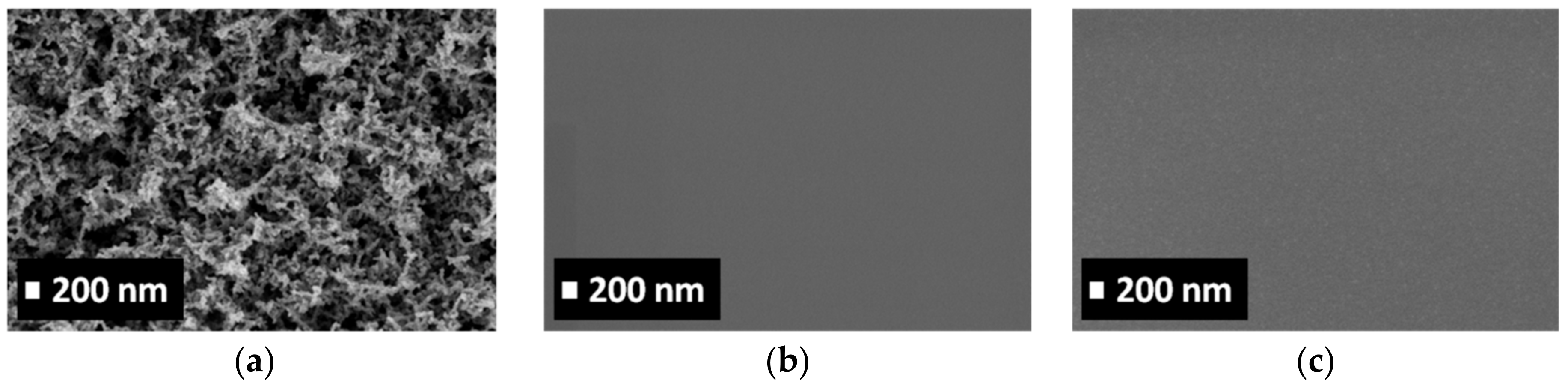
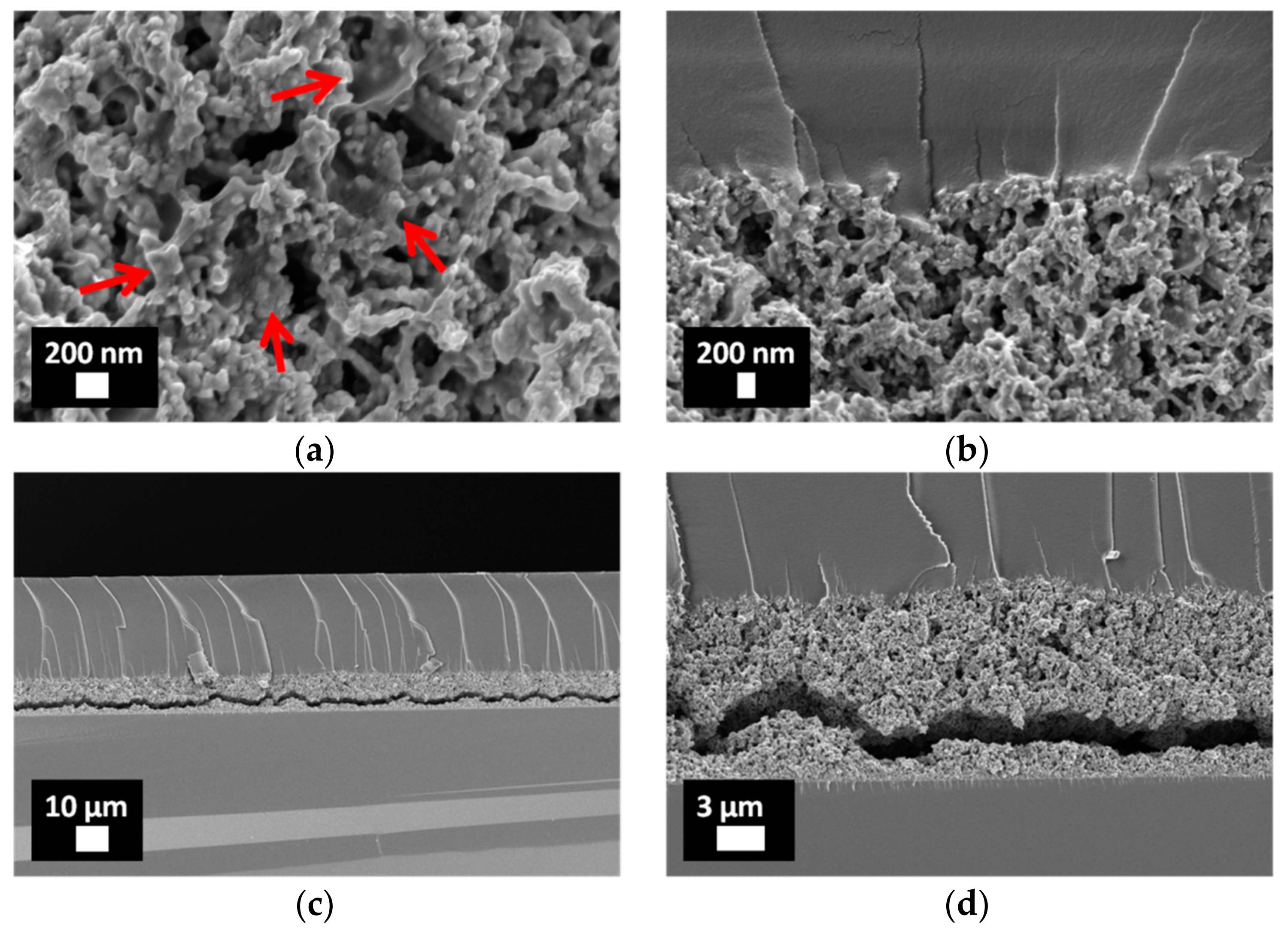
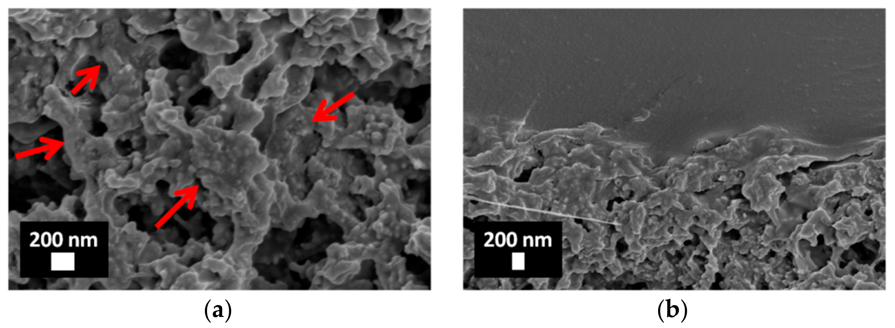
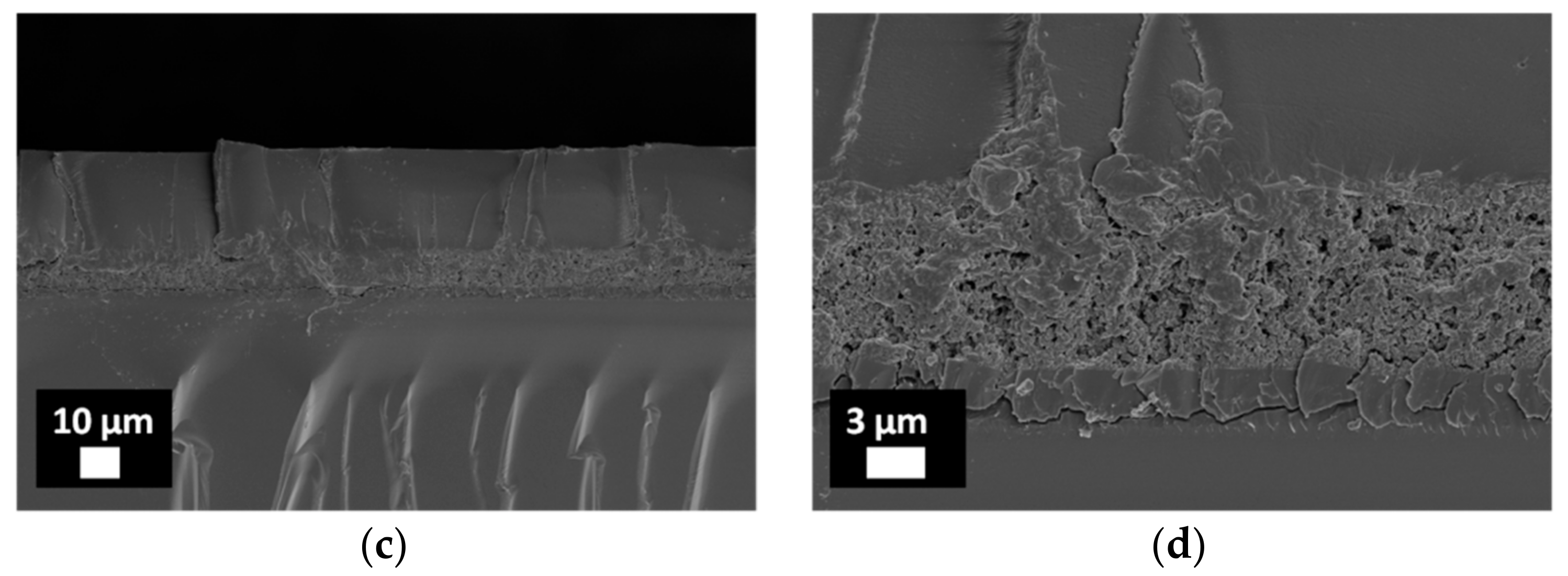
3.2. Characterization of Porous ZnO/Polymer Bilayer Systems

The presence of pHEMA and p(HEMA-co-AA) polymer coatings atop of the mesoporous ZnO films was first confirmed by the FTIR analyses (Figure S3 of SI).
Figure 3 shows the evolution of the surface morphology for the mesoporous ZnO matrix, before and after drop-casting the two different polymer solutions (i.e., pHEMA and p(HEMA-co-AA)). If the starting ZnO sample is considered (Figure 3a), a rough surface with nano-branched ZnO crystals forming cavities and a mesoporous structure can be observed. The corresponding degree of porosity, that is, 14 m2 g−1, with a pore volume of 0.095 cm3 g−1, was previously estimated by nitrogen adsorption–desorption isotherm analyses [45]. After drop casting the pHEMA and p(HEMA-co-AA) solutions, the morphology heavily changes, with a flat and smooth surface in both the cases (Figure 3b,c), indicating a complete and uniform coating of the polymers on the ZnO porous structure. If the vacuum-infiltrated ZnO/polymer samples are considered (Figure S4 of SI), surfaces featuring similar morphologies can be observed as well. Therefore, no substantial differences affecting the surface morphology of the ZnO/polymer samples are detected if the drop-casting and vacuum infiltration methods are considered.
In contrast, the cross-section of the vacuum-infiltrated and drop-casted samples is strongly different if it is analyzed. Figure 4 shows the cross-section view of the ZnO/pHEMA bilayer samples obtained after the vacuum infiltration. A high-magnification view of the structure is reported in Figure 4a, with red arrows highlighting that the infiltration of pHEMA within the mesoporous and nanostructured ZnO matrix has successfully occurred, without the clogging of the existing pores at all. The formation of a well-defined and continuous interface between the pHEMA coating and the underlying mesoporous ZnO structure is also visible in Figure 4b. However, if the ZnO/Si substrate interface is considered (Figure 4c,d), the presence of cracks within the ZnO layer is noticed, and suggests a possible detachment of ZnO from the Si support.
Figure 5a,b shows that the vacuum infiltration method was also suitable for infiltrating the copolymer within the mesoporous ZnO matrix, featuring morphological characteristics similar to those that were obtained for the homopolymer case (see Figure 5a,b to compare). The interface between the copolymer coating and the mesoporous ZnO structure is well-defined again, despite the ZnO/Si substrate interface exhibiting also the presence of cracks (Figure 5c,d).
The morphology of the ZnO/polymer samples obtained using the drop-casting technique is shown in Figure 6. Both the polymers, that is, pHEMA and p(HEMA-co-AA), well infiltrated the ZnO matrix, as highlighted by the red arrows of Figure 6a,c. The uniform impregnation of the matrix shows similar characteristics, and a well-defined interface between ZnO and the polymer coating is obtained also in this case, as is visible from Figure 6b,d.
The cracks within the mesoporous ZnO matrix and the resulting partial detachment from the Si support observed for the vacuum-infiltrated samples can be inferred to the presence of low-vacuum conditions during the infiltration process, which most likely induced a faster solvent evaporation than for the drop-casting approach, and led to a rapid expansion of the ZnO structure, also due to the possible presence of air entrapped within the ZnO pores. This conclusion is strengthened by the FESEM analyses performed on the drop-casted ZnO/polymer samples (Figure 6), highlighting that no crack within the ZnO film near the substrate is present. Actually, drop-casting was performed at atmospheric pressure, without forcing the methanol evaporation using low vacuum conditions. Another limitation of the vacuum infiltration approach is related to the polymer film thickness. Independently of the considered polymer, the vacuum-infiltrated coatings had an average thickness of around 30 μm. On the other hand, the drop-casting of the polymeric solutions allowed for avoiding the detachment of the porous ZnO matrix from the Si support, and to limit the polymer coating thickness at the same time, which was around 3 μm. Therefore, by considering the absence of any detachment and cracks, high structural stability and integrity, and the reduced polymer coating thickness, the drop-casting method was selected as the best approach in order to fabricate the ZnO/polymer bilayer systems, and the corresponding calcein release properties were thereafter evaluated.

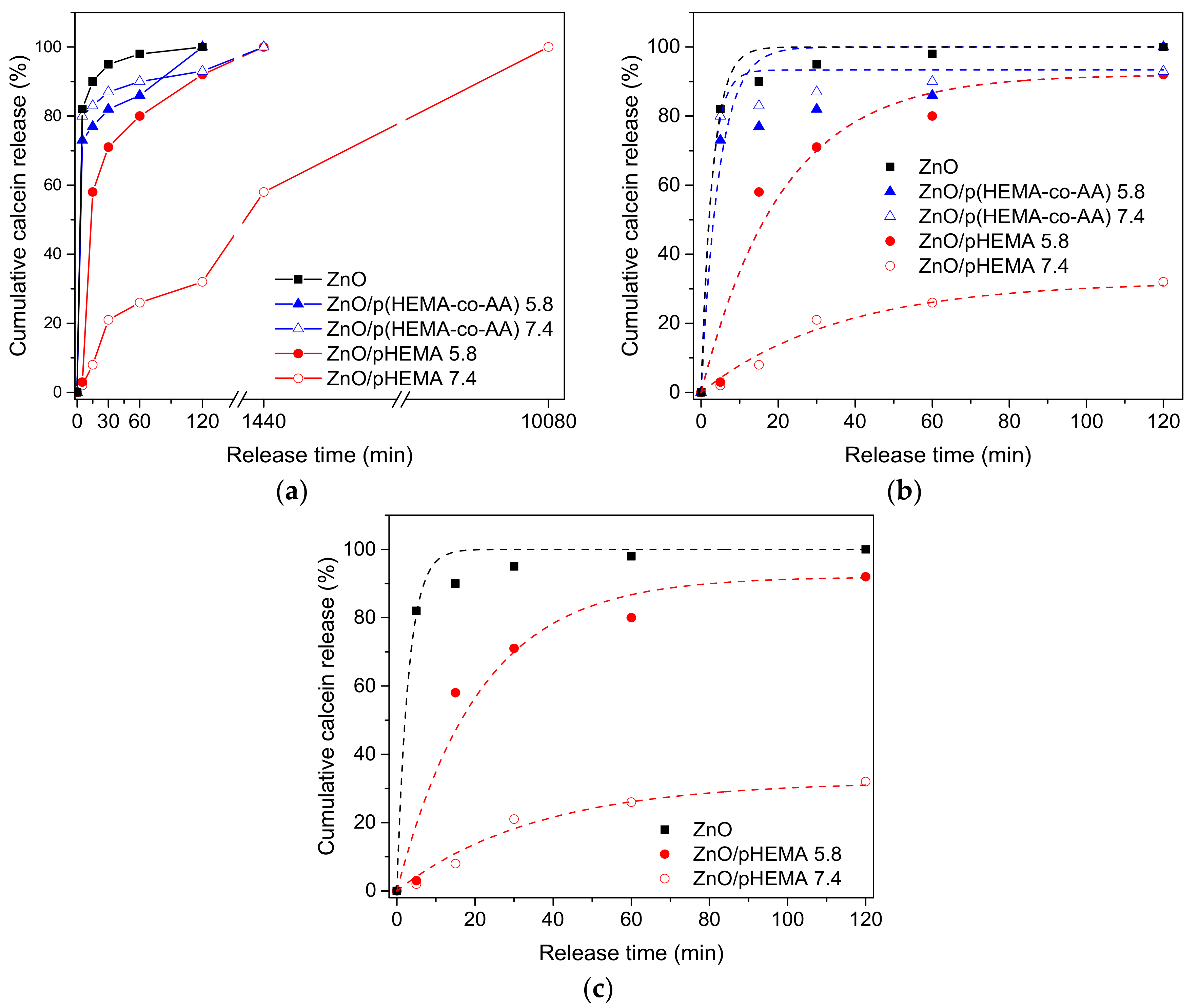
3.3. pH-Triggered Release of Calcein from Drop-Casted ZnO/pHEMA and ZnO/p(HEMA-co-AA) Bilayer Coatings

Calcein was loaded in the porous ZnO films for 2 h at room temperature. A picture representative of the calcein-loaded ZnO sample is reported in Figure 7a, which highlights the color change of the ZnO sample after calcein adsorption, and witnesses the successful loading of the fluorescent dye within the host porous matrix.
The calcein release was first monitored for the pure ZnO samples in the SBF solution (pH 7.4) at 37 °C, by considering the time evolution of the UV absorption peak characteristic for the calcein dye (Figure S5 of SI). The corresponding release profile (Figure 8a, black line) follows a pseudo-first-order exponential decay law (Figure 8b, dotted black line), with a release rate constant of 0.33 min−1, representing that the calcein release from the porous ZnO film is governed by a simple diffusion mechanism. An important burst effect characterizing the release profile is present, with more than 90% of the calcein released within 30 min, and the complete release (100%) occurring after 120 min. The molecule release profile was then monitored in similar conditions (SBF, pH 7.4, 37 °C) after drop casting pHEMA and p(HEMA-co-AA) polymer films atop of the calcein-loaded porous ZnO matrix. The UV spectra of the corresponding release solutions are reported in Figure S6 of SI. Independently of the kind of polymer, the release kinetic appeared slower, as visible from the release profiles of Figure 8a. However, Figure 8b highlights some of the important differences between the two family of samples, especially for the short release times. For the sample ZnO/pHEMA, the release was more effectively slowed down, with only 32% calcein delivered after 120 min, then approaching 60% after 24 h. This incomplete calcein release is further represented in Figure 7b, showing that the sample of ZnO/pHEMA still appeared colored after 24 h. Hence, a sustained delivery was demonstrated in this case, with the calcein release continuing for an overall time period of seven days. For the sample ZnO/p(HEMA-co-AA), a faster calcein release was observed, with ~90% calcein delivered after 120 min and 100% delivered after 24 h. This is represented in Figure 7c as well, showing that after 24 h, the sample was totally white (i.e., the typical color of pure ZnO film). Anyway, despite showing a faster kinetic than for ZnO/pHEMA, the presence of the copolymer coating partially mitigated the burst effect affecting the pure ZnO.
To evaluate the effect of the pH variation on calcein delivery, the release experiments were also performed in a buffered pH 5.8 solution at 37 °C. It is actually aimed at exerting control over the delivery kinetics in an environment that can be physiologically achieved in ureters. The acidification of urine is both a physiological and therapeutic process, which can be obtained by diet, acidifying drugs or compounds, metabolism, or diseases [46,47]. As urinary acidification at a pH below 5.5 poses a substantial risk of uric acid precipitation (although this pH would be protective against calcium phosphate precipitation) [48], in this study, we decided to maintain our acidification degree at a physiological value of pH 5.8.
For pure ZnO, the sudden dissolution of the porous matrix occurred after soaking the sample for few minutes, because of the fast degradation typical of ZnO-based materials when interacting with acidic media [30,49]. Therefore, a quantitative evaluation of the calcein release for the pure ZnO was only possible for neutral pH conditions. On the other hand, such degradation was prevented if the ZnO/polymer bilayer systems are considered. This is due to the presence of the polymer coatings, which successfully worked as barrier layers and prevented the sudden dissolution of the mesoporous ZnO matrix upon interaction with an acidic environment. As previously observed, the pure ZnO matrix showed a fast calcein delivery. After drop-casting the polymers, the kinetic release was generally slowed down, especially when the homopolymer pHEMA was considered. A similar behavior was found in acidic conditions as well, as shown in Figure 8b. However, for the sample of ZnO/p(HEMA-co-AA), the release kinetic did not seem to be significantly improved, as 100% calcein was released after 120 min (i.e., the same release time as obtained for pure ZnO). However, a lower kinetic can be observed for shorter release times; after 60 min, 86% calcein was released against the 98% measured for pure ZnO. If the sample ZnO/pHEMA is considered, a slightly different behavior is observed, with 80% calcein released after 60 min, approaching 100% only after 24 h.
The interesting pH-responsive behavior of the sample of ZnO/pHEMA is more effectively visible for shorter times (120 min), as reported in Figure 8c. It can be observed that, for neutral pH conditions, the presence of pHEMA successfully allowed for controlling the calcein delivery with respect to pure ZnO. The stability of the ZnO/pHEMA system, once interacting with SBF solution, also allowed the sustained calcein release for up to seven days, while the complete delivery occurred after only 120 min for the raw ZnO matrix. Upon interaction with a slight acidic environment, the swelling of the HEMA polymer was increased [38], thereby accelerating the kinetic release with respect to the neutral pH conditions. This effect was more pronounced for the copolymer coating. Despite acrylic acid being a pH-sensitive monomer, its ability to improve the swelling properties of HEMA is also recognized [38,39]. This pronounced swelling effect, already observed in neutral pH conditions, was further visible at the end of the release experiment (i.e., 100% calcein release); the presence of the copolymer coating atop the porous ZnO matrix was no longer visible. On the contrary, the pHEMA coating was still present at the same point of time. However, it is worth mentioning that some micrometric defects started to be visible as well, as shown in Figure 9.
The successfulness of the ZnO/pHEMA bilayer system for the sustained calcein delivery is well-represented considering the corresponding kinetic parameters listed in Table 1. It can be observed that, independently of the pH value, the presence of pHEMA effectively allowed for the reduction of the kinetic release, with respect to pure ZnO. More interestingly, it is also observable that the calcein release is pH-triggered, in this case; neutral conditions highly lower the release of calcein, while it can be increased in the presence of a slight acidic environment. Even though all of the profiles follow the same pseudo-first-order exponential decay law, representing the diffusion mechanisms, the release rate constant drops to 0.03 min−1 and 0.05 min−1 for the ZnO/pHEMA bilayer system at pH 7.4 and 5.8, respectively. For the copolymer coating, the kinetic constant is slightly equal to pure ZnO (0.38 min−1). It is worth mentioning that, for the acidic media, the complete calcein release was reached after 24 h in the best case, and after shorter release times in the others. This was due to the complete degradation of the polymer coatings, which also induced the dissolution of the mesoporous ZnO film. This result also confirms the potential biodegradability of the developed coatings for further ureteral stent applications. For neutral pH conditions, the polymer coating was only partially damaged (Figure 9), with the micrometric holes working as preferential channels along which calcein could easily diffuse out from the porous ZnO matrix.
Finally, it can be summarized that two interesting effects are observed for the sample ZnO/pHEMA, as follows: (1) with respect to pure ZnO, the presence of the polymer pHEMA lowered the kinetic at pH conditions similar to those of the urinary system, and a sustained release is obtained for seven days; (2) for slightly acidic conditions (pH 5.8), it is possible to monitor the ZnO degradation and to accelerate the release kinetics of the overall ZnO/pHEMA system at the same time, also avoiding the undesirable burst effect observed for pure ZnO. The abovementioned properties envision the future possibilities in the use of ZnO/pHEMA coatings for drug eluting ureteral stents with sustained and pH-controlled delivery properties obtained by changing the pH conditions of the stent environment. Usually, acidifying drugs that temporarily decrease the urine pH are administered to the patients in order to dissolve the calcium phosphate encrustations affecting the urinary tract and the stent in place [48,50]. Despite the different time scales existing between the kinetic release of the proposed ZnO/polymer coatings (exhausting within 7 days in the best scenario) and the development of encrustations (several weeks), this local pH increase could also be effectively exploited to activate/accelerate the release of other drug molecules, like anti-inflammatory or antibiotics, previously loaded within the ZnO/pHEMA eluting coating.

4. Conclusions

Porous ZnO thin films coupled with pHEMA and p(HEMA-co-AA) polymer coatings were successfully fabricated by vacuum infiltration and drop-casting techniques. The morphological analyses pointed out that drop-casting was the most suitable method to avoid the development of cracks within the porous ZnO matrix, and for an appropriate polymer film thickness as well. For the pure ZnO matrix, the release experiments showed an important burst effect and a fast kinetic, with 100% calcein released after 120 min. On the other hand, the presence of the polymer coatings partially limited the undesirable burst effect and slowed down the calcein kinetic release. In particular, the pHEMA coating successfully allowed the following: (i) to create a barrier layer that prevented the sudden release of the molecule loaded within the porous ZnO matrix; (ii) to achieve a sustained release for up to seven days in neutral pH conditions; (iii) to implement a pH-triggered delivery system by moving from neutral to acidic pH conditions.

Supplementary Materials

The following are available online at https://www.mdpi.com/2079-6412/8/11/376/s1, Figure S1: (a) Overview of the radio-frequency (RF) magnetron sputtering monotarget system used for the deposition of Zn coatings; (b) View of the inner part of the deposition chamber, Figure S2: Overview of the apparatus used for the preparation of ZnO/polymer bilayer samples by vacuum infiltration method, Figure S3: FTIR spectra for ZnO/pHEMA and ZnO/p(HEMA-co-AA) samples, obtained by (a) drop-casting and (b) vacuum infiltration method. No additional contributions coming from the porous ZnO layer are detected in both the cases because the characteristic ZnO IR modes fall out from the detection range of the ATR-FTIR setup, i.e., at wavenumber lower than 525 cm−1, Figure S4: Top-view FESEM images of porous ZnO thin films on Si substrate: (a) before polymer infiltration; (b) after vacuum infiltration of the pHEMA solution; (c) after vacuum infiltration of the p(HEMA-co-AA) solution. Scale bar is 200 nm, Figure S5: UV spectra of calcein release solutions from the mesoporous ZnO matrix, performed in aqueous SBF solution at physiological pH conditions and 37 °C, Figure S6: UV spectra of calcein release solutions for (a) ZnO/pHEMA at pH 7.4, (b) ZnO/pHEMA at pH 5.8, (c) ZnO/p(HEMA-co-AA) at pH 7.4, (d) ZnO/p(HEMA-co-AA) at pH 5.8.

Author Contributions

Conceptualization, M.L., M.G. and V.C.; Data Curation, V.C.; Funding Acquisition, M.G. and V.C.; Investigation, M.L. and M.G.; Methodology, M.L. and M.G.; Resources, M.G. and V.C.; Supervision, V.C.; Validation, V.C.; Writing–Original Draft, M.L. and M.G.; Writing–Review & Editing, M.L. and V.C.

Funding

This work was funded by a STSM grant from the COST Action CA16217 “ENIUS” and funded by COST (European Cooperation in Science and Technology).

Acknowledgments

The authors gratefully acknowledge Salvatore Guastella and Carla Celozzi for their assistance with the FESEM analyses.

Conflicts of Interest

The authors declare no conflict of interest.

References

  1. Gultepe, E.; Nagesha, D.; Sridhar, S.; Amiji, M. Nanoporous inorganic membranes or coatings for sustained drug delivery in implantable devices. Adv. Drug Deliv. Rev. 2010, 62, 305–315. [Google Scholar] [CrossRef] [PubMed]
  2. Felton, L.A.; Porter, S.C. An update on pharmaceutical film coating for drug delivery. Expert Opin. Drug Deliv. 2013, 10, 421–435. [Google Scholar] [CrossRef] [PubMed]
  3. La, W.G.; Park, S.; Yoon, H.H.; Jeong, G.J.; Lee, T.J.; Bhang, S.H.; Han, J.Y.; Char, K.; Kim, B.S. Delivery of a therapeutic protein for bone regeneration from a substrate coated with graphene oxide. Small 2013, 9, 4051–4060. [Google Scholar] [CrossRef] [PubMed]
  4. Kang, H.J.; Kim, D.J.; Park, S.J.; Yoo, J.B.; Ryu, Y.S. Controlled drug release using nanoporous anodic aluminum oxide on stent. Thin Solid Films 2007, 515, 5184–5187. [Google Scholar] [CrossRef]
  5. Gulati, K.; Ramakrishnan, S.; Aw, M.S.; Atkins, G.J.; Findlay, D.M.; Losic, D. Biocompatible polymer coating of titania nanotube arrays for improved drug elution and osteoblast adhesion. Acta Biomater. 2012, 8, 449–456. [Google Scholar] [CrossRef] [PubMed]
  6. Salonen, J.; Kaukonen, A.M.; Hirvonen, J.; Lehto, V.P. Mesoporous silicon in drug delivery applications. J. Pharm. Sci. 2008, 97, 632–653. [Google Scholar] [CrossRef] [PubMed]
  7. Leung, J.W.C.; Lau, G.T.C.; Sung, J.J.Y.; Costerton, J.W. Decreased bacterial adherence to silver-coated stent material: An in vitro study. Gastrointest. Endosc. 1992, 38, 338–340. [Google Scholar] [CrossRef]
  8. Cauda, V.; Chiodoni, A.; Laurenti, M.; Canavese, G.; Tommasi, T. Ureteral double-J stents performances toward encrustation after long-term indwelling in a dynamic in vitro model. J. Biomed. Mater. Res. B 2017, 105, 2244–2253. [Google Scholar] [CrossRef] [PubMed]
  9. Cauda, F.; Cauda, V.; Fiori, C.; Onida, B.; Garrone, E. Heparin coating on ureteral double J stents prevents encrustations: An in vivo case study. J. Endourol. 2008, 22, 465–472. [Google Scholar] [CrossRef] [PubMed]
  10. Laube, N.; Kleinen, L.; Bradenahl, J.; Meissner, A. Diamond-like carbon coatings on ureteral stents—A new strategy for decreasing the formation of crystalline bacterial biofilms? J. Urol. 2007, 177, 1923–1927. [Google Scholar] [CrossRef] [PubMed]
  11. John, T.; Rajpurkar, A.; Smith, G.; Fairfax, M.; Triest, J. Antibiotic pretreatment of hydrogel ureteral stent. J. Endourol. 2007, 21, 1211–1215. [Google Scholar] [CrossRef] [PubMed]
  12. Leung, J.W.; Liu, Y.L.; Cheung, S.W.; Chan, R.C.Y.; Inciardi, J.F.; Cheng, A.F. Effect of antibiotic-loaded hydrophilic stent in the prevention of bacterial adherence: A study of the charge, discharge, and recharge concept using ciprofloxacin. Gastrointest. Endosc. 2001, 53, 431–437. [Google Scholar] [CrossRef] [PubMed]
  13. Cormio, L.; La Forgia, P.; La Forgia, D.; Siitonen, A.; Ruutu, M. Bacterial adhesion to urethral catheters: Role of coating materials and immersion in antibiotic solution. Eur. Urol. 2001, 40, 354–358. [Google Scholar] [CrossRef] [PubMed]
  14. Thierry, B.; Merhi, Y.; Silver, J.; Tabrizian, M. Biodegradable membrane-covered stent from chitosan-based polymers. J. Biomed. Mater. Res. A 2005, 75A, 556–566. [Google Scholar] [CrossRef] [PubMed]
  15. Fu, W.; Wang, Z.; Li, G.; Cui, F.; Zhang, Y.; Zhang, X. Comparison of a biodegradable ureteral stent versus the traditional double-J stent for the treatment of ureteral injury: An experimental study. Biomed. Mater. 2012, 7, 065002. [Google Scholar] [CrossRef] [PubMed]
  16. Chew, B.H.; Paterson, R.F.; Clinkscales, K.W.; Levine, B.S.; Shalaby, S.W.; Lange, D. In vivo evaluation of the third generation biodegradable stent: A novel approach to avoiding the forgotten stent syndrome. J. Urol. 2013, 189, 719–725. [Google Scholar] [CrossRef] [PubMed]
  17. Lo, J.; Lange, D.; Chew, B.H. Ureteral stents and foley catheters-Associated Urinary tract infections: The role of coatings and materials in infection prevention. Antibiotics 2014, 3, 87–97. [Google Scholar] [CrossRef] [PubMed]
  18. Wang, L.; Hu, C.; Shao, L. The antimicrobial activity of nanoparticles: Present situation and prospects for the future. Int. J. Nanomed. 2017, 12, 1227–1249. [Google Scholar] [CrossRef] [PubMed]
  19. Huh, A.J.; Kwon, Y.J. “Nanoantibiotics”: A new paradigm for treating infectious diseases using nanomaterials in the antibiotics resistant era. J. Control. Release 2011, 156, 128–145. [Google Scholar] [CrossRef] [PubMed]
  20. Zhu, P.; Weng, Z.; Li, X.; Liu, X.; Wu, S.; Yeung, K.W.K.; Wang, X.; Cui, Z.; Yang, X.; Chu, P. Biomedical applications of functionalized ZnO nanomaterials: From biosensors to bioimaging. Adv. Mater. Interfaces 2016, 3, 150049. [Google Scholar] [CrossRef]
  21. Racca, L.; Canta, M.; Dumontel, B.; Ancona, A.; Limongi, T.; Garino, N.; Laurenti, M.; Canavese, G.; Cauda, V. Zinc oxide nanostrucutres in biomedicine. In Smart Nanoparticles for Biomedicine; Ciofani, G., Ed.; Elsevier Inc.: Amsterdam, The Netherlands, 2018; pp. 171–187. [Google Scholar]
  22. Sirelkhatim, A.; Mahmud, S.; Seeni, A.; Kaus, N.H.M.; Ann, L.C.; Bakhori, S.K.M.; Hasan, H.; Mohamad, D. Review on zinc oxide nanoparticles: Antibacterial activity and toxicity mechanism. Nano-Micro Lett. 2015, 7, 219–242. [Google Scholar] [CrossRef]
  23. Cauda, V.; Stassi, S.; Lamberti, A.; Morello, M.; Pirri, C.F.; Canavese, G. Leveraging ZnO morphologies in piezoelectric composites for mechanical energy harvesting. Nano Energy 2015, 18, 212–221. [Google Scholar] [CrossRef]
  24. Chiolerio, A.; Roppolo, I.; Cauda, V.; Crepaldi, M.; Bocchini, S.; Bejtka, K.; Verna, A.; Pirri, C.F. Ultraviolet mem-sensors: Flexible anisotropic composites featuring giant photocurrent enhancement. Nano Res. 2015, 8, 1956–1963. [Google Scholar] [CrossRef]
  25. Hernandez, S.; Hidalgo, D.; Sacco, A.; Chiodoni, A.; Lamberti, A.; Cauda, V.; Tresso, E.; Saracco, G. Comparison of photocatalytic and transport properties of TiO2 and ZnO nanostructures for solar-driven water splitting. Phys. Chem. Chem. Phys. 2015, 17, 7775–7786. [Google Scholar] [CrossRef] [PubMed]
  26. U.S. Food and Drug Administration. Available online: https://www.accessdata.fda.gov/scripts/cdrh/cfdocs/cfcfr/CFRSearch.cfm?fr=182.8991 (accessed on 12 September 2018).
  27. Laurenti, M.; Verna, A.; Fontana, M.; Stassi, S.; Canavese, G.; Marasso, S.L.; Cauda, V. How micropatterning and surface functionalization affect the wetting behavior of ZnO nanostructured surfaces. Adv. Mater. Interfaces 2016, 3, 1600110. [Google Scholar] [CrossRef]
  28. Laurenti, M.; Cauda, V. Porous zinc oxide thin films: Synthesis approaches and applications. Coatings 2018, 8, 67. [Google Scholar] [CrossRef]
  29. Rivera, V.F.; Auras, F.; Motto, P.; Stassi, S.; Canavese, G.; Celasco, E.; Bein, T.; Onida, B.; Cauda, V. Length-dependent charge generation from vertical arrays of high-aspect-ratio ZnO nanowires. Chem. A Eur. J. 2013, 19, 14665–14674. [Google Scholar] [CrossRef] [PubMed]
  30. Dumontel, B.; Canta, M.; Engelke, H.; Chiodoni, A.; Racca, L.; Ancona, A.; Limongi, T.; Canavese, G.; Cauda, V. Enhanced biostability and cellular uptake of zinc oxide nanocrystals shielded with a phospholipid bilayer. J. Mater. Chem. B 2017, 5, 8799–8813. [Google Scholar] [CrossRef] [PubMed] [Green Version]
  31. Cauda, V.; Pugliese, D.; Garino, N.; Sacco, A.; Bianco, S.; Bella, F.; Lamberti, A.; Gerbaldi, C. Multi-functional energy conversion and storage electrodes using flower-like Zinc oxide nanostructures. Energy 2014, 65, 639–646. [Google Scholar] [CrossRef]
  32. Miccoli, B.; Cauda, V.; Bonanno, A.; Sanginario, A.; Bejtka, K.; Bella, F.; Fontana, M.; Demarchi, D. One-dimensional ZnO/gold junction for simultaneous and versatile multisensing measurements. Sci. Rep. 2016, 6, 29763. [Google Scholar] [CrossRef] [PubMed]
  33. Laurenti, M.; Cauda, V. ZnO nanostructures for tissue engineering applications. Nanomaterials 2017, 7, 374. [Google Scholar] [CrossRef] [PubMed]
  34. Laurenti, M.; Cauda, V. Gentamicin-releasing mesoporous ZnO structures. Materials 2018, 11, 314. [Google Scholar] [CrossRef] [PubMed]
  35. Ancona, A.; Dumontel, B.; Garino, N.; Demarco, B.; Chatzitheodoridou, D.; Fazzini, W.; Engelke, H.; Cauda, V. Lipid-coated zinc oxide nanoparticles as innovative ROS-generators for photodynamic therapy in cancer cells. Nanomaterials 2018, 8, 143. [Google Scholar] [CrossRef] [PubMed]
  36. Nair, S.; Sasidharan, A.; Rani, V.V.D.; Menon, D.; Nair, S.; Manzoor, K.; Raina, S. Role of size scale of ZnO nanoparticles and microparticles on toxicity toward bacteria and osteoblast cancer cells. J. Mater. Sci. Mater. Med. 2009, 20, 235–241. [Google Scholar] [CrossRef] [PubMed]
  37. Montheard, J.P.; Chatzopoulos, M.; Chappard, D. 2-Hydroxyethyl methacrylate (HEMA)—Chemical-properties and applications in biomedical fields. J. Macromol. Sci. Part C Polym. Rev. 1992, C32, 1–34. [Google Scholar] [CrossRef]
  38. Yarimkaya, S.; Basan, H. Swelling behavior of poly(2-hydroxyethyl methacrylateco-acrylic acid-co-ammonium acrylate) hydrogels. J. Macromol. Sci. A 2007, 44, 939–946. [Google Scholar] [CrossRef]
  39. Omidian, H.; Park, K.; Kandalam, U.; Rocca, J.G. Swelling and mechanical properties of modified HEMA-based superporous hydrogels. J. Bioact. Compat. Pol. 2010, 25, 483–497. [Google Scholar] [CrossRef]
  40. Zhang, Y.; Chan, H.F.; Leong, K.W. Advanced materials and processing for drug delivery: The past and the future. Adv. Drug Deliver Rev. 2013, 65, 104–120. [Google Scholar] [CrossRef] [PubMed] [Green Version]
  41. Lai, J.; Wang, T.; Li, Y.; Tu, I. Synthesis, characterization and ocular biocompatibility of potential keratoprosthetic hydrogels based on photopolymerized poly(2-hydroxyethyl methacrylate)-co-poly(acrylic acid). J. Mater. Chem. 2012, 22, 1812–1823. [Google Scholar] [CrossRef]
  42. Kokubo, T.; Takadama, H. How useful is SBF in predicting in vivo bone bioactivity? Biomaterials 2006, 27, 2907–2915. [Google Scholar] [CrossRef] [PubMed]
  43. Guan, Y.; Zhang, Y.; Zhou, T.; Zhou, S. Stability of hydrogen-bonded hydroxypropylcellulose/poly(acrylic acid) microcapsules in aqueous solutions. Soft Matter 2009, 5, 842–849. [Google Scholar] [CrossRef]
  44. Yang, S.; Zhang, Y.; Wang, L.; Hong, S.; Xu, J.; Chen, Y. Composite thin film by hydrogen-bonding assembly of polymer brush and poly(vinylpyrrolidone). Langmuir 2006, 22, 338–343. [Google Scholar] [CrossRef] [PubMed]
  45. Sacco, A.; Lamberti, A.; Gazia, R.; Bianco, S.; Manfredi, D.; Shahzad, N.; Cappelluti, F.; Ma, S.; Tresso, E. High efficiency dye-sensitized solar cells exploiting sponge-like ZnO nanostructures. Phys. Chem. Chem. Phys. 2012, 14, 16203–16208. [Google Scholar] [CrossRef] [PubMed]
  46. Brodsky, W.A.; Carrasquer, G. Mechanisms of acidification of the urine. Prog. Cardiovasc. Dis. 1961, 4, 105–133. [Google Scholar] [CrossRef]
  47. Barrett, K.E.; Barman, S.M.; Boitano, S.; Brooks, H.L. Acidification of the urine & bicarbonate excretion. In Ganong’s Review of Medical Physiology, 25th ed.; Weitz, M., Kearns, B., Eds.; McGraw-Hill Education: New York, NY, USA, 2016. [Google Scholar]
  48. Moe, O.W.; Preisig, P.A. Dual role of citrate in mammalian urine. Curr. Opin. Nephrol. Hypertens. 2006, 15, 419–424. [Google Scholar] [CrossRef] [PubMed]
  49. Fatehah, M.O.; Aziz, H.A.; Stoll, S. Stability of ZnO nanoparticles in solution. Influence of pH, dissolution, aggregation and disaggregation effects. J. Coll. Sci. Biotechnol. 2014, 3, 75–84. [Google Scholar] [CrossRef]
  50. Moe, O.W. Uric acid nephrolithiasis: Proton titration of an essential molecule? Curr. Opin. Nephrol. Hypertens. 2006, 15, 366–373. [Google Scholar] [CrossRef] [PubMed]
Figure 1. The FTIR spectra of the polymers hydrophilic 2-hydroxyethyl methacrylate p(HEMA) (black) and p(HEMA-co-acrylic acid (AA)) (red).
Coatings 08 00376 g001
Figure 2. The 1H NMR spectra of pHEMA and p(HEMA-co-AA).
Coatings 08 00376 g002
Figure 3. Top-view field-emission scanning electron microscope (FESEM) images of porous ZnO thin films: (a) before polymer infiltration; (b) after drop-casting the pHEMA solution; (c) after drop-casting the p(HEMA-co-AA) solution.
Coatings 08 00376 g003
Figure 4. Cross-section view FESEM images for porous ZnO thin film on a Si substrate after vacuum infiltration with a pHEMA solution (10 wt %). (a) Infiltration of pHEMA (red arrows) within the porous ZnO matrix; (b) view of the interface between the pHEMA coating and the underlying ZnO matrix; (c,d) view of the cracks within the ZnO layer.
Coatings 08 00376 g004
Figure 5. Cross-section view FESEM images for porous ZnO thin film on a Si substrate after vacuum infiltration with a p(HEMA-co-AA) solution (10 wt %). (a) Infiltration of p(HEMA-co-AA) (red arrows) within the porous ZnO matrix; (b) view of the interface between the p(HEMA-co-AA) coating and the underlying ZnO matrix; (c,d) view of the cracks within the ZnO layer.
Coatings 08 00376 g005aCoatings 08 00376 g005b
Figure 6. Cross-section view FESEM images for porous ZnO thin film on an Si substrate after drop-casting the polymer solution: (a,b) pHEMA; (c,d) p(HEMA-co-AA). The presence of fragments alongside the cross-section is due to the cleavage of the samples, which induced the breaking of the polymer coating in some cases.
Coatings 08 00376 g006
Figure 7. Pictures representative of the following: (a) porous ZnO thin film on Si wafer, after calcein loading; (b) sample ZnO/pHEMA after calcein release in simulated body fluid (SBF) for 24 h; (c) sample ZnO/p(HEMA-co-AA) after calcein release in SBF for 24 h.
Coatings 08 00376 g007
Figure 8. Cumulative release profile for calcein: (a) within 7 days; (b) within 120 min; (c) within 120 min, by changing the pH of the release solution.
Coatings 08 00376 g008
Figure 9. FESEM images of the sample of ZnO/pHEMA at the end of the release experiment in SBF, at different magnifications, namely: (a) 100×; (b) 1000×.
Coatings 08 00376 g009
Table 1. Kinetic parameters of calcein released from pure ZnO and ZnO/polymer systems. p(HEMA)—polymers hydrophilic 2-hydroxyethyl methacrylate; AA—acrylic acid.
MaterialpH(w120min/w0), %K (min−1)Χ2
ZnO7.41000.33 ± 0.050.98
ZnO/pHEMA7.4320.03 ± 0.010.98
5.8920.05 ± 0.010.95
ZnO/p(HEMA-co-AA)7.4930.38 ± 0.080.98
5.81000.21 ± 0.070.85

