Article

Texturing Effect of Crater-Like Cavities Induced by High-Current Pulsed Electron Beam (HCPEB) Irradiation

1
School of Mechatronics Engineering, Harbin Institute of Technology, Harbin 150001, China
2
School of Materials Science and Engineering, Harbin Institute of Technology, Harbin 150001, China
*
Author to whom correspondence should be addressed.
Coatings 2018, 8(10), 355; https://doi.org/10.3390/coatings8100355
Submission received: 2 August 2018 / Revised: 22 September 2018 / Accepted: 4 October 2018 / Published: 5 October 2018

Abstract

:
High-current pulsed electron beam (HCPEB) irradiation commonly induces crater-like cavities on irradiated surfaces, making them tribologically resemble textured ones. However, the effect of crater-like cavities on the lubricated tribological properties of HCPEB-treated surfaces has not been reported in the literature. This work was aimed at exploring the potential texturing effect of the crater-like cavities. Surfaces with continuous and uniform crater-like cavities were prepared through HCPEB irradiating a 400-nm thick Ta coating that was pre-deposited on polished M50 steel. Their boundary tribological behaviors were studied while sliding in chemically inert, low-viscosity hydrocarbon fuel JP-10 against a Si3N4 ball under 2.0–4.0 GPa. At 2.0 GPa, the coefficient of friction (COF) and wear rate of the polished M50 steel were above 0.16 on average, with large fluctuation, and 1.49 × 10⁻⁵ mm3/N·m (a rectangle-like profile of 167.9 μm × 8.1 μm), respectively. In comparison, the HCPEB-treated Ta coating had a stable, marginally fluctuant COF of 0.11 and a near-zero wear rate. Under other higher loads, the HCPEB-treated Ta coating still exhibited a stable COF of 0.11 on average with small fluctuation, and its wear track width was only half that of the M50 steel. The analysis of the wear topographies indicates that the substantial reduction in both the COF and wear rate was mainly due to the texturing effect originating from the crater-like cavities.

1. Introduction

High-current pulsed electron beam (HCPEB) irradiation has been developed as an ever-increasingly attractive technique for the surface modification and alloying of metallic materials [1,2,3,4]. Low-energy (up to 40 keV), high-current (up to 40 J/cm2) electron beams rush into the top surface layer within a pulse duration on a microsecond scale (~2–3 μs), causing superfast heating, melting, evaporation, and solidification (~107–9 K/s), together with thermal stress and shock waves. This superfast heating–cooling thermal cycle leads to significant change in the surface microstructure with modified physical and chemical properties, e.g., hardness [5,6,7,8], corrosion resistance [6,8,9,10,11] and oxidation resistance [12,13,14].
Recently, the effect of HCPEB irradiation on the tribological properties of treated samples has received more and more attention. Dry sliding friction tests by Guo et al. [8] showed that the wear resistance of Ti6Al4V alloy almost remained unvaried before and after HCPEB irradiation. Xu et al. [15] found that HCPEB irradiation significantly weakened the wear resistance of M50 steel when dry sliding against a Si3N4 ball in ambient atmosphere, which was attributed to the increase in austenite content in the melted layer. In contrast, a reduction in both the friction coefficient and wear rate was reported with AZ91HP magnesium alloy [10] and Al–Pb alloy [16] after HCPEB treatment in atmospheric dry sliding conditions. Ivanov et al. [17] found that HCPEB-irradiated commercial drills exhibited an enhanced wear resistance in comparison with unirradiated ones and TiN-coated ones. More studies have demonstrated that various HCPEB-treated alloys and steel achieved an improved wear resistance, but the number of pulses [5,9,18,19] and energy density [20,21] had a significant impact on the wear resistance. Irradiated films/coatings were also proven to be more wear-resistant than the bare substrate and as-deposited state by atmospheric dry friction tests. For example, fretting tests by Dong et al. [22] showed that the original D2-Cr12Mo1V1 alloy had less than 100 cycles prior to the failure point when the friction coefficient rose abruptly while sliding against a GCr15 bearing steel ball, but the cycle number was increased to nearly 2000 after HCPEB-irradiating a Cr coating on the alloy surface, indicating that the surface alloying by Cr significantly enhanced the fretting wear resistance. Rotshtein et al. [23] found that HCPEB-irradiated copper film exhibited a lower friction coefficient and a narrower wear track than the original film (512 ± 30 nm) sputtered on austenitic steel SS 316 in pin-on-disc wear tests with a WC indenter. Despite large amounts of work focused on dry friction performance and relevant wear mechanisms, there has been little research that has studied the lubricated tribological properties of HCPEB-irradiated surfaces.
The electron beam irradiation causes a near-surface layer (several microns) to melt and erupt [6,24,25,26]. As a result, large numbers of crater-like cavities are formed, which are commonly the most typical feature of HCPEB-treated surfaces [8,15,24,25,26,27,28,29], and are also viewed as a category of surface defect [12,30]. The cavity size is greatly influenced by irradiation parameters and substrate materials, with diameters ranging from several microns [30] to tens of microns [15,25,26,28,31,32], even to a few hundred microns [6,29], and depth from a few microns [26,29,32] to tens of microns [24]. The amount of cavities is intimately dependent on the HCPEB pulse number [6,8,12,24,27,28,29,30,32] and energy density [29,30,33]. In particular, the presence of crater-like cavities makes the irradiated surfaces resemble textured ones from the viewpoint of tribology [27,28,30,31,32]. Since the pioneering work of Hamilton et al. [34] and Anno et al. [35], it has been well-recognized that surface texture can co-work with the counterpart to produce additional fluid hydrodynamic pressure to increase the total load-carrying capacity [36], thereby reducing friction and wear under boundary lubrication conditions. Surface texture has been widely employed to improve the tribological performance of various components, including thrust bearings [37,38], journal bearings [39,40], piston rings [41,42], mechanical seals [43], and magnetic storage devices [44]. However, the effect of crater-like cavities on the tribological performance of HCPEB-treated surfaces under lubricated conditions has not been reported in the literature.
The goal of this present work was to explore the potential texturing effect from the crater-like cavities by ball-on-disc friction tests under boundary lubrication. HCPEB-treated surfaces with continuous and uniform crater-like cavities were prepared by first depositing and then HCPEB-irradiating a Ta coating on M50 bearing steel. Ta is known for its excellent high temperature stability and chemical inertness [45], and these properties can minimize the impact of tribochemistry on its tribological behaviors. Chemically inert, low-viscosity hydrocarbon fuel Jet Propellant-10 (JP-10, C10H16) [46] and a Si3N4 ball were used as the lubricating medium and counterpart in the friction tests, respectively. A significant reduction in both friction coefficient and wear rate was achieved by the HCPEB-treated Ta coating in a series of high-load conditions (2.0–4.0 GPa) compared to bare M50 steel, which was primarily due to the texturing effect originating from the crater-like cavities.

2. Materials and Methods

2.1. Preparation of HCPEB-Treated Ta Coating

Quenched M50 bearing steel with a hardness of around 62.5 HRC was used as the substrate for Ta coating deposition. Commercial M50 steel sample was austenitized at 1100 ± 5 °C for 35 min in a vacuum furnace followed by gas quenching. Then, the sample was subjected to three tempering cycles. The tempering process temperature and duration were 550 ± 10 °C and 120 min, respectively. Finally, the quenched M50 steel was composed of martensite, retained austenite, and a small quantity of carbides, and its nominal chemical composition (wt. %) is as follows [27]: C, 0.75–0.85 wt. %; Si, ≤0.35 wt. %; Mn, ≤0.35 wt. %; Cr, 3.75–4.25 wt. %; Mo, 4.00–4.50 wt. %; V, 0.90–1.10 wt. % and Fe, balance. The steel specimen was machined to φ50 mm × 5 mm discs. One of the flat surfaces of a disc was polished to mirror finish with a surface roughness (Ra) of 0.05–0.08 μm.
A 400-nm thick Ta coating was first deposited on polished M50 steel in argon at a pressure of 0.5 Pa by direct current magnetron sputtering in a DLZ-01 system including film/coating deposition and HCPEB treatment units [47]. A pure Ta target (φ50 mm × 5 mm, 99.95% in molar fraction) was used for the deposition. The sputtering system was operated at direct current of 1000 V and 2 A. Other sputtering parameters were: a substrate bias voltage of −100 V, a target power of 140 W, a sputtering power of 35 W, and a sputtering time of 720 s. With a constant target voltage (350 V) and current (0.06 A), the deposited thickness was controlled by the sputtering time (depositing time). After the deposition, the coating side was rotated to face the electron gun (electron beam diameter ≤100 mm) for HCPEB irradiation [47]. The electron beam unit (RITM-2M) mainly consisted of an electron gun (a plasma anode and an explosive emission cathode), a high-voltage pulse generator, a control system, and a power supply. The HCPEB treatment was carried out in argon at a pressure of 4 × 10⁻² Pa with the following specific parameters: a pulse duration of 2.5 μs, an energy density of 6 J/cm2, the irradiation number 10 with a pulse interval time of 10 s, an acceleration voltage of 33 kV, and the distance from substrate to cathode of 130 mm.

2.2. Morphology Characterization

Surface and cross-section morphologies of the HCPEB-treated Ta coating were examined by scanning electron microscope (SEM, Quanta 200FEG, FEI Instruments Co., Ltd., Hillsboro, OR, USA) equipped with energy-dispersive X-ray spectroscopy (EDS) to acquire morphology and chemical composition information. A SEM/EDS topography characterization is shown in Figure 1. Figure 1a shows that the topography was mainly featured by crater-like cavities continuously and uniformly distributed across from the surface. A typical cavity was depicted in region A, and its high-magnification image in Figure 1b clearly exhibits the internal volcanic appearance: it is concave in the center and convex at the edge. The EDS area-scanning spectrum (Figure 1c) of Ta in region A and point spectra 1–3 (Figure 1d–f) reveal that the element Ta was primarily distributed in the convex areas, and that almost no Ta was detected on the bottom. With high-current electron beam irradiation, the several-micron-thick near-surface layer of the underlying M50 steel substrate melted and explosively erupted [27], causing the upper Ta magma to spatter. Due to the ultra-rapid solidification (~107–9 K/s) [1,2,3,4] of Ta magma, Ta was mainly accumulated around the eruption site. Adjacent eruption increased the accumulation in the same area, thereby forming the wave-like appearance of “hills and valleys”, as illustrated by the overview topography in Figure 1a. A cross-section SEM image of a typical protrusion is shown in Figure 1g, which indicates that the Ta alloying layer was packed uniformly and densely with a thickness of about 8 μm. Almost no sharp coating/substrate interface was observed due to the welding effect between the coating and the steel substrate, which considerably raised the interfacial bonding strength.
The Ta alloying layer surface was also observed under laser confocal scanning microscope (LCSM, OLS3000, Olympus Co., Shinjuku, Tokyo, Japan). A 1.28 mm × 1.28 mm LCSM graph is shown in Figure 2a, in which two crossed profiles (a horizontal line at 956.3 μm and a vertical line at 406.2 μm) were selected to illustrate the dimension of the crater-like cavities. The cavity diameter (or width) varied, ranging from several dozen to a few hundred microns, while the depth remained relatively stable at approximately 35 ± 5 μm. The profiles indicate that the surface roughness of the top and near-top areas of protrusions was relatively low. The obvious fluctuation of the profiles in the bottom areas was caused by the presence of carbide particles [27]. The carbide particles have different physical properties (e.g., melting point) from the quenched M50 steel matrix, and are believed to be the cores of eruption where crater-like cavities are formed during HCPEB irradiation. With an increasing number of pulses, the amount of craters decreases due to the dissolution of the carbide particles. The graph was further transformed into a color-filled contour graph as shown in Figure 2b, which vividly depicts the HCPEB-treated Ta coating surface appearance as “hills and valleys”.

2.3. Nano-Indentation Tests

The hardness and elastic modulus of the HCPEB-treated Ta coating were determined by the Oliver–Pharr method [48] from nano-indentation tests by MTS Nano Indenter XP (MTS Systems Co., Eden Prairie, MN, USA) at room temperature. A three-sided diamond pyramid (Bercovich) probe was used, and the tests were based on the continuous stiffness measurements mode. The indentation depth limit was approximately 1000 nm, and Figure 3a shows the load–displacement curve. The hardness (Figure 3b) and elastic modulus (Figure 3c) virtually witnessed the same variation trend with the depth: sequentially a sharp and gradual increase to peak values (approximately 14.7 GPa and 260 GPa at around 400 nm, respectively) followed by a slight fall to about 10.7 GPa and 230 GPa at the maximum depth, respectively. The synchronous drop in hardness and elastic modulus from around 500 nm could be attributed to the influence of the underlying M50 steel substrate according to Bueckle’s rule [49].

2.4. Friction Tests

Friction tests of HCPEB-treated Ta coating were performed using the ball-on-disc model of the Universal macro Materials Tester 3 (UMT-3, Tribology and Mechanical Testing Unit, Bruker Co., Billerica, MA, USA) at room temperature in ambient atmosphere. The counterpart was a Si3N4 ball with Ra 0.03–0.04 μm and hardness of 90 HRC, and pure JP-10 was directly used as the lubricating medium as received.
JP-10 is essentially a single-component hydrocarbon, i.e., exo-tetrahydrodicyclopentadiene (C10H16), which is synthetically produced by the hydrogenation of dicyclopentadiene [46,50,51,52]. The molecular configuration of JP-10 is shown in Figure 4a, which is present as a strained cyclic structure without any functional group. Due to the special strained cyclic geometry, JP-10 has high volumetric energy density, and therefore, it is an ideal fuel for volume-limited combustion chambers [53,54]. Figure 4b shows the hydrogen and carbon atoms with numberings. There are only C–C and C–H bonds in the saturated molecule. In particular, the JP-10 molecule is nearly non-polar (dipole moment 0.02 Debye) and has no symmetry plane [55,56]. JP-10’s viscosity is around 2.7 mPa·s at room temperature [46,57], which is quite approximate to that (1 mPa·s) of water, but far lower than those (10–1000 mPa·s) of conventional lubricating oils, suggesting that JP-10 is a low-viscosity liquid with good low-temperature fluidity.
To maintain bath lubrication under which the potential texturing effect from the crater-like cavities would not be obstructed, the tribopair was completely steeped in JP-10 throughout a friction test. The disc was driven to perform a clockwise rotational motion against the stationary Si3N4 ball. The tribological system can partly mimic the contact form of fuel pump ceramic ball hybrid bearings (M50 steel raceways and Si3N4 balls) in gas turbine engines without conventional oil lubrication systems. The sliding speed v was set at a constant value of 100 mm/s and the applied normal loads FN were 9.1 N, 45.6 N, 78.9 N, 125.2 N, and 187.5 N, corresponding to the theoretical maximum Hertz contact pressures P of 2.0 GPa, 2.5 GPa, 3.0 GPa, 3.5 GPa, and 4.0 GPa, respectively. The selected speed and loads can effectively simulate the boundary lubrication conditions of fuel pump bearings at starting-up and shutting-down moments. According to the force-measuring ranges of UMT-3 sensors DFM-2 (0.2–20 N) and DFH-100 (10–1000 N), φ3.96-mm Si3N4 balls were used for friction tests under 9.1 N, while φ6.35-mm Si3N4 balls were used under other high loads. To show the reality and endurance of the tribological performance, the total cycle number n was set at 10,000 for a friction test. Thus, the sliding distance l depended on the sliding radius r of the ball on the disc. To show the effect of surface modification on the tribological performance, bare (polished) M50 steel was used as reference. The friction test conditions are listed in Table 1. Prior to a test, the tribopair was cleaned in an ultrasonic alcohol bath for 5 min. During a test, the friction curve was recorded in situ. After friction tests, all of the wear tracks were examined by LCSM and/or coupled SEM/EDS to develop an insight into the wear topography and chemical composition to reveal the wear rate and wear mechanisms.

3. Results

3.1. Coefficient of Friction

Figure 5 shows the friction curves of the polished M50 steel and HCPEB-treated Ta coating while sliding in pure JP-10 against a Si3N4 ball under 2.0–4.0 GPa. “M50 COF” and “Ta COF” are used to designate the coefficients of friction (COFs) of the M50 steel and HCPEB-treated Ta coating, respectively. Figure 5a shows that the Ta COF was always significantly lower than the M50 COF throughout the friction test at 2.0 GPa. The former virtually remained constant at around 0.11, while the later gradually increased from an average of 0.12 to above 0.16 as the friction test proceeded. Another remarkable feature is that the Ta COF fluctuated marginally compared to the M50 COF. These sharp contrasts in COF were also observed under 2.5–4.0 GPa, as shown in Figure 5b–e. The increase in load almost did not change the value of Ta COF, yet made the fluctuation a little stronger. In contrast, the M50 COF increased and became more fluctuant under these higher loads. Overall, the Ta COF was significantly lower, far more stable, and considerably less fluctuant than the M50 COF in these testing load conditions.

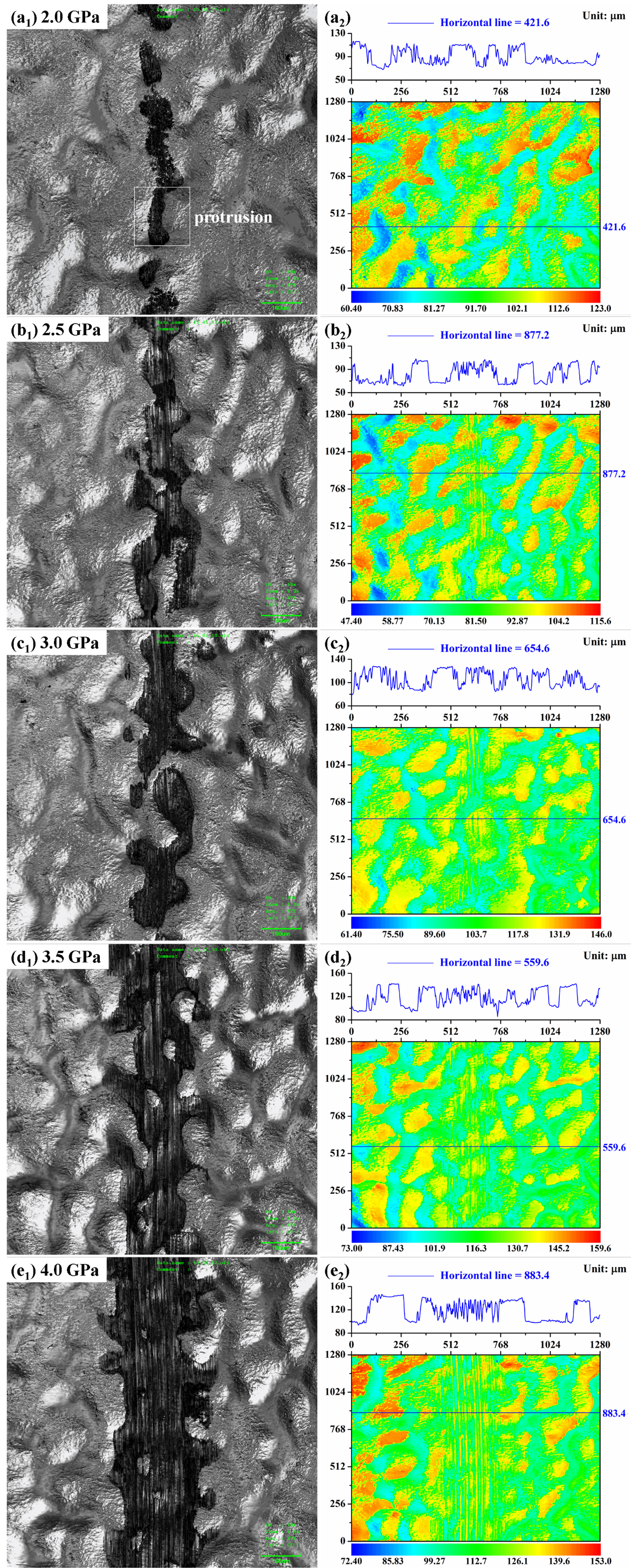
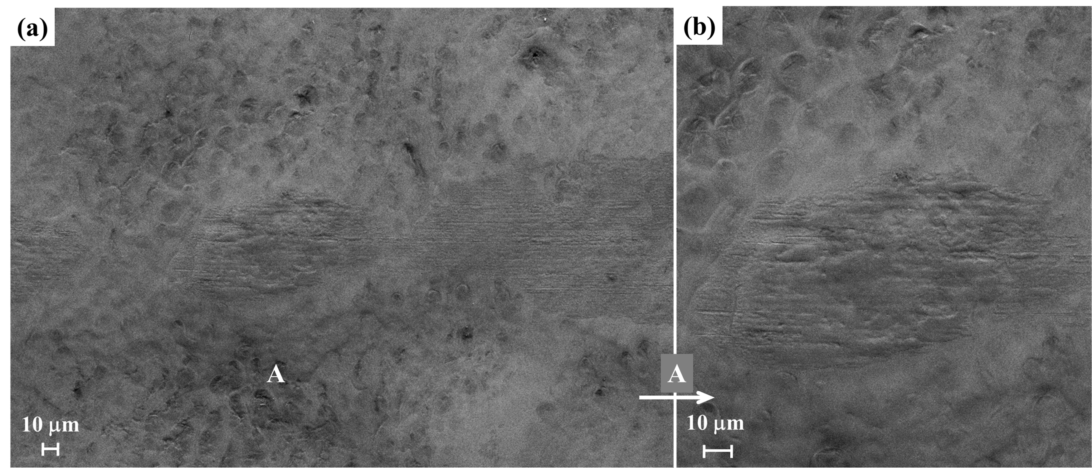
3.2. Wear Topography

3.2.1. Polished M50 Steel

Figure 6a shows the SEM wear topography of polished M50 steel after the friction test in pure JP-10 under 2.0 GPa, which was featured by dark coverings. The high-magnification image (Figure 6b) of a typical region A exhibits scale-like appearance (large cracks) and partial spalling (e.g., point 1) of the covering layer, indicating that the covering layer had been subjected to serious fatigue wear caused by repeated shear contact. EDS analyses were carried out at points 1 and 2, representing the exposed surface after spalling and the dark covering, respectively. Spectrum 1 in Figure 6c shows that the detected chemical composition was very approximate to that of original M50 steel; thus, this exposed surface was fresh M50 steel matrix. Spectrum 2 in Figure 6d reveals that an extra, large amount of oxygen (up to 19.7 wt %) was detected at point 2, indicating that the covering layer had been heavily oxidized during the friction test. Except for fatigue cracking and spalling, the covering layer was also uniformly peeled off along the sliding direction under ploughing action from the counterpart (Figure 6a), indicating the occurrence of considerable abrasive wear. The analysis of the wear topography reveals that the wear loss was primarily from the partial fatigue spalling and large-scale ploughing peeling off of the thick oxidation-covering layers. Apparently, serious oxidation significantly lowered the resistance of fatigue and abrasion of M50 steel. Therefore, it is the tribo-oxidation that dictated the friction and wear behaviors of M50 steel while sliding in pure JP-10 against the Si3N4 ball at room temperature in ambient atmosphere. The relevant wear mechanism was a combined mode of tribo-oxidation-based fatigue and abrasive wear. The wear topography feature and wear mechanism did not change in other higher load conditions (2.5–4.0 GPa).

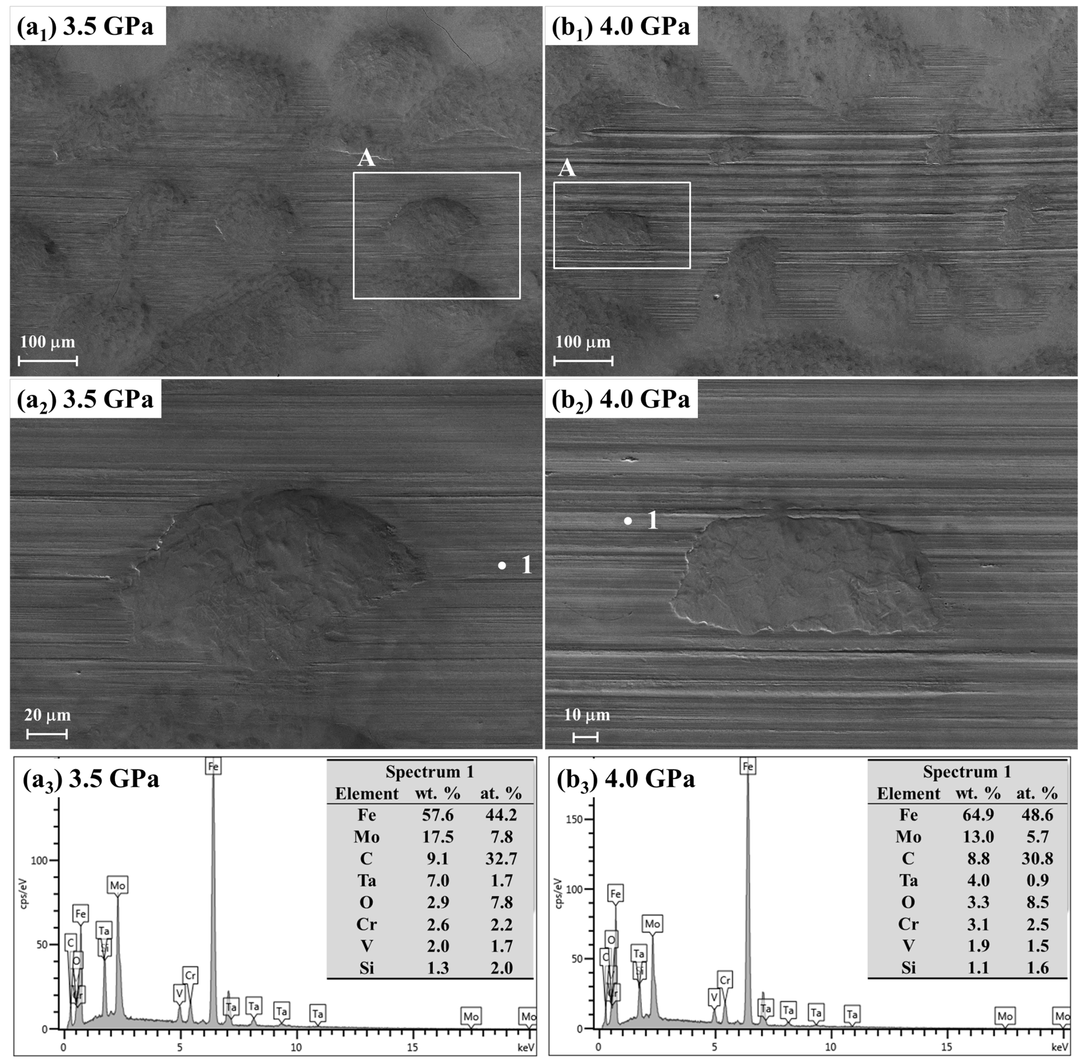
3.2.2. HCPEB-Treated Ta Coating

Figure 7 displays the LCSM wear topographies and corresponding contour graphs of the HCPEB-treated Ta coating after the friction tests in pure JP-10 under the series of load conditions (2.0–4.0 GPa). These LCSM images unambiguously show that the most attention-drawing feature for all of the wear tracks was the interruption of friction contact (the dark areas) at cavities. At 2.0 GPa, the real contact area (Figure 7(a1)) almost cannot be identified by the color difference (reflecting height difference) in the contour graph in Figure 7(a2). To illustrate wear loss, a profile at 421.6 μm was carefully selected, crossing a typical protrusion corresponding to the boxed area in Figure 7(a1). However, the profile was unable to show the wear loss of this protrusion that had undergone 10,000 repeated hard sliding contacts. At such a typical protrusion, the wear loss was around zero; thus, it can be believed that there was almost no wear loss in other contact areas. After raising the load to 2.5 GPa, wear loss in the contact areas, e.g., at the profile of 877.2 μm, was identifiable in the contour graph in Figure 7(b2). With further increasing the load, the wear track became wider, indicating a larger wear loss, especially at the protrusions. As indicated by Figure 7(b2,c2), the basic wave-like appearance of “hills and valleys” remained relatively intact after the friction test under 2.5 GPa and 3.0 GPa, although identifiable wear occurred. In comparison, the protrusion areas experienced apparent damage under 3.5 GPa and 4.0 GPa, as shown in Figure 7(d2,e2).
Figure 8a shows the SEM wear topography of the HCPEB-treated Ta coating under 2.0 GPa. The friction contact was interrupted at cavities, as observed with LCSM. The high-magnification image (Figure 8b) of protrusion A shows that thin furrows were almost the only feature on the wear scar, indicating that abrasion was the predominant wear mechanism. Figure 9 shows the SEM/EDS characterization of the HCPEB-treated Ta coating after the friction test under 3.5 GPa and 4.0 GPa. Entire crater-like cavities were frequently observed on the widened wear tracks. High-magnification images of cavity regions A in Figure 9(a1,b1) are shown in Figure 9(a2,b2), respectively. Except for the cavities, furrows were the main feature of the wear topographies. Despite the considerable wear loss, Ta was still rich on the wear scars, as indicated by the EDS spectra in Figure 9(a3,b3). Compared to the unrubbed area, a small quantity of extra oxygen (approximately 3 wt. %) was detected in the contact area. The presence of oxygen was due to the oxidation of the Ta alloying layer [58]. In particular, thick and dark oxidation layers were not formed, whose ploughing peeling off and fatigue spalling were the primary reasons for the aggressive wear of bare M50 steel (Figure 6). Therefore, abrasion was predominantly responsible for the wear. The abrasion and oxidation should be weaker in the lower load conditions.

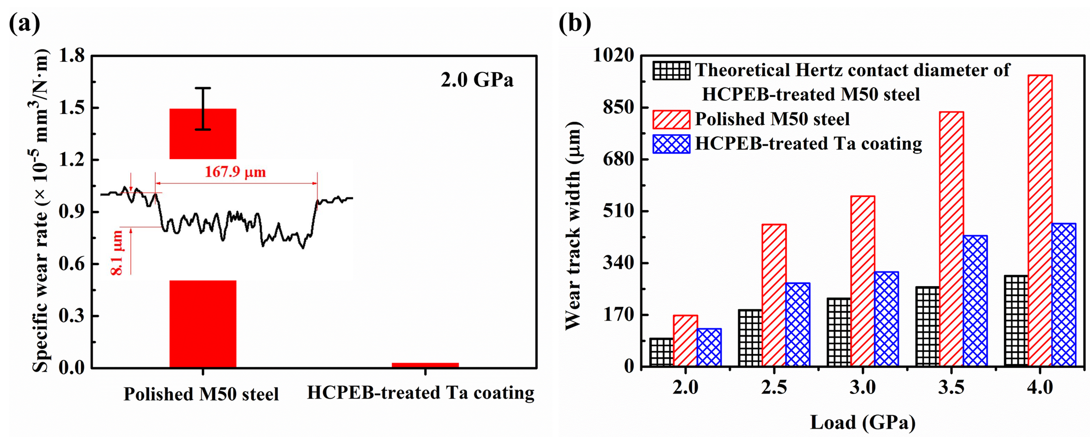
3.3. Specific Wear Rate

The insert in Figure 10a shows the rectangle-like wear profile of the polished M50 steel after the friction test under 2.0 GPa. The cross-section dimension was around 167.9 μm × 8.1 μm; thus, the specific wear rate we was approximately 1.49 × 10⁻⁵ mm3/N·m, as calculated by the following equation:
  w e = V F N · l  
where V is the wear volume in mm3; FN is the normal load in N; and l is the sliding distance in m. In contrast, the specific wear rate of the HCPEB-treated Ta coating was approximately zero in the same testing condition, as suggested by the LCSM wear topography in Figure 7(a1) and contour graph in Figure 7(a2). Figure 10a shows the wear rate comparison at 2.0 GPa.
Due to the presence of cavities on the wear tracks, the wear rate of HCPEB-treated Ta coating cannot be calculated by Equation (1). Figure 10b gives the wear track widths in comparison with those of polished M50 steel under 2.0–4.0 GPa. The wear track width of HCPEB-treated Ta coating was almost only half of that of polished M50 steel at 2.5–4.0 GPa, indicating that the wear rate was significantly lowered after alloying Ta coating in these high-load conditions. The theoretical Hertz contact radius a between an Si3N4 ball and an HCPEB-treated M50 steel surface can be calculated by Hertz contact formula with the parameters in Table 2:
  a = 3 F N D 8 ( 1 μ 1 2 E 1 + 1 μ 2 2 E 2 ) 3  
where FN is the normal load applied onto the ball, N; D is the ball diameter, m; E is the elastic modulus, Pa; and μ is the Poisson ratio. After HCPEB treatment, the elastic modulus of M50 steel decreases from 260 GPa to around 210 GPa; thus, the Hertz contact radius of the irradiated M50 steel is slightly larger than that of the untreated M50 steel in the same load condition. The Hertz contact radius on the HCPEB-treated M50 steel should be approximate to that on the M50-steel-based HCPEB-treated Ta coating, because the Ta alloying layer was merely several microns thick. As can be seen from Figure 10b, both wear tracks were wider than the theoretical Hertz contact diameter b under each load, but the HCPEB-treated Ta coating wear track width was close to the Hertz contact diameter, indicating that the specific wear rate of the HCPEB-treated Ta coating was relatively low.

4. Discussion

4.1. Improved Boundary Tribological Performance

All of the COFs were above 0.1 (Figure 5), and a large scale of direct asperity-to-asperity contact occurred in every friction test (Figure 7, Figure 8 and Figure 9), indicating that the lubricating medium JP-10 did not separate the relatively sliding surfaces. Thus, the lubrication regime of all of the friction tests that were present in this work was boundary lubrication. The severe wear, accompanied by high and considerably fluctuant COF, indicates that the lubricity of JP-10 itself was unable to effectively protect the tribopart: the bare M50 steel. However, depositing and alloying the Ta coating gave rise to a shift of the wear mechanism from a combined mode of tribo-oxidation-based fatigue and abrasion to a single abrasion. This concomitantly led to a remarkable reduction in both COF and wear rate, indicating a substantial improvement in the boundary tribological performance of M50 steel while sliding in the pure, low-viscosity fuel JP-10 under a series of high-load conditions. In particular, the stable, marginally fluctuant COF of 0.11 and the wear rate of nearly zero under 2.0 GPa almost reflected the best tribological performance that was available under the boundary lubrication regime. COF’s variation and fluctuation usually cause noise and vibration, which could adversely impact the service life and reliability of tribosystems and other related components. The near-zero wear rate implies that almost no wear debris went into JP-10 after completing a sliding distance of up to 596.6 m. The blending of impurities from wear into fuel could degrade the combustion performance, and even damage the fuel injection equipment or engines, which should be absolutely avoided. Therefore, the considerable reduction in friction and wear demonstrates that proper surface modification is able to overcome the wear problems caused by the inadequate lubricity of low-viscosity fuel when directly used as a lubricating medium, making it promising to remove the conventional oil lubrication systems from fuel injection systems [59] and/or discard the incorporation of additives into fuel [60].

4.2. Texturing Effect from the Crater-Like Cavities

The severe tribo-oxidation of bare M50 steel indicates that atmospheric oxygen resolved into JP-10 and then oxidized the active surfaces exposed after asperity-to-asperity contact. It is well known that a Ta coating/film will be oxidized to form self-lubricious Ta2O5 with a low COF during ambient friction [58,61,62,63]. The M50 steel wear topography (2.0 GPa, Figure 6) clearly shows the formation of thick and dark oxidation layers on the wear track, but similar oxidation layers were not observed on the worn Ta alloying coating (2.0 GPa, Figure 8; 3.5 and 4.0 GPa, Figure 9). The EDS spectra in Figure 9 reveal that merely around 3 wt. % oxygen was detected on the worn HCPEB-treated Ta coating under 3.5 GPa and 4.0 GPa, which is far less than that (about 20 wt. %, Figure 6) on the worn M50 steel at 2.0 GPa. These comparisons in wear topography and chemical composition demonstrate that the tribo-oxidation of Ta alloying coating was quite weak. Yet, very thin protective Ta2O5 films could be formed on the worn surfaces, which effectively inhibited the invasion of oxygen toward the inner layer and M50 steel substrate [63,64,65,66]. Therefore, the excellent boundary tribological performance of HCPEB-treated Ta coating cannot be primarily attributed to the self-lubricious properties of the lubricious oxide films (e.g., Ta2O5) that were formed on the wear track during the friction test.
JP-10 has high thermal and oxidative stability, and its operation conditions involve highly elevated temperature (1000–2500 K) and pressure (1–100 bar) [50,51,57,67]. Therefore, it can be believed that JP-10 was not involved in the chemical reactions, but merely acted as an inert lubricating medium during the friction tests in the selected speed and load conditions at room temperature in ambient atmosphere. As there are only C–C and C–H bonds in the non-polar molecule, the JP-10 molecule did not chemically adsorb on the M50 steel, HCPEB-treated Ta coating, or Si3N4 ball to form a robust boundary layer. The JP-10 molecule might weakly and reversibly adsorb through simple physical adhesion driven by entropic force, forming a boundary layer that is different from the bulk phase. The JP-10 molecule is strained cyclic and has a low molecular weight of 136 g/mol, strongly suggesting that the physically adsorbed JP-10 molecule boundary layer was thin (i.e., a couple of molecules thick) and had a low load-carrying capacity. As indicated by the wear topography of M50 steel (Figure 6), the physically adsorbed JP-10 molecule boundary layer cannot effectively prevent large-scale direct contact at the lowest testing load of 2.0 GPa. Therefore, the adsorption of JP-10 was not the key factor that determined the tribological performance of the HCPEB-treated Ta coating.
As seen in Figure 7, friction contact was mostly interrupted at crater-like cavities in any load condition. Figure 8 shows that the counterpart Si3N4 ball did not contact the valley bottom area between neighboring protrusions. Figure 9 shows that the counterpart slid over cavities (e.g., an ellipse-like cavity in Figure 9(a2) and a rectangle-like one in Figure 9(b2)), and did not touch the concave wall at all. Unambiguously, the wear topographies of the HCPEB-treated Ta coating are exactly the typical wear topographies of textured surfaces [68,69,70,71,72,73,74,75,76]. Therefore, the crater-like cavities were working as a surface texture while the HCPEB-treated Ta coating was sliding in JP-10 against the Si3N4 ball. During the relative motion, the Si3N4 ball and the cavity outward slope edges formed converging gaps where additional fluid hydrodynamic pressure of JP-10 was built up due to the wedging effect. This local pressure lift increased the load-carrying capacity of the JP-10 that was confined in these gaps. Consequently, local asperity-to-asperity contact strength was weakened, and even the amount of direct contact spots was effectively reduced, thereby leading to a substantial reduction in friction and wear. Additionally, the crater-like cavities made some other contributions [36]: (1) working as reservoirs to entrain JP-10 into the impending friction interface and cool contact spots to weaken adhesion, and (2) trapping wear debris to reduce abrasive wear.

4.3. HCPEB: a Potential Surface Texturing Technique

The presence of the crater-like cavities, indeed, makes the HCPEB-treated Ta coating tribologically resemble textured surfaces. Due to the uncontrollability of HCPEB irradiation, the distribution density, shape, size, and orientation of the cavities cannot be precisely acquired. However, the SEM and LCSM topographies in Figure 1, Figure 7, Figure 8 and Figure 9 show that the cavity distribution was still relatively continuous and uniform, and that the majority of the cavities were quite quasi-circular with approximate diameter and depth. Moreover, the crossed profiles in the LCSM contour graphs in Figure 2 and Figure 7 indicate that the wave-like surface was flat with a relatively low surface roughness except for the bottom areas. Overall, the HCPEB-treated Ta coating was a high-quality textured surface with excellent boundary tribological performance while sliding against a Si3N4 ball in the pure, low-viscosity fuel JP-10 under a series of high-load conditions (2.0–4.0 GPa). Therefore, this present work strongly suggests that HCPEB irradiation is a potential surface texturing technique that can induce texture-functioning crater-like cavities on the treated surfaces such as coatings/films for friction and wear reduction under lubricated conditions.

5. Conclusions

A high-current pulsed electron beam was used to irradiate a Ta coating that was pre-deposited on M50 bearing steel by magnetron sputtering. The boundary tribological behaviors of both polished M50 steel and HCPEB-treated Ta coating were studied while sliding in chemically inert, low-viscosity fuel JP-10 against a Si3N4 ball under a series of high-load conditions (2.0–4.0 GPa) at room temperature in ambient atmosphere. Based on an in-depth discussion on the friction curves and wear topographies, the following conclusions can be drawn:
(1)
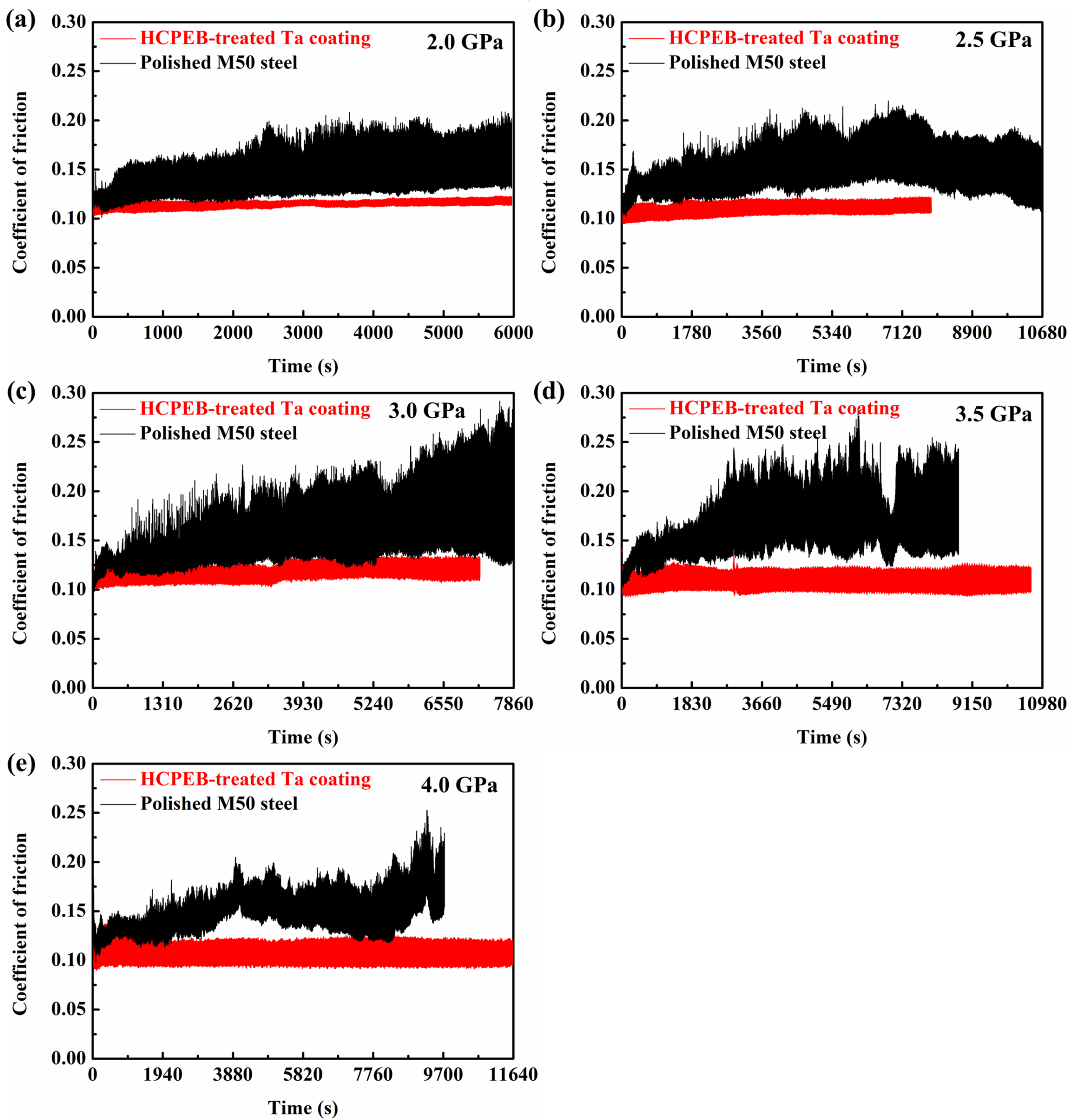
Polished M50 steel underwent severe wear due to tribo-oxidation under any testing load, accompanied by a considerably fluctuant COF of above 0.16 on average at a steady friction stage. After depositing and alloying the Ta coating, the COF became significantly lower, far more stable, and considerably less fluctuant. The wear track width of the HCPEB-treated Ta coating was almost only half that of M50 steel at 2.5–4.0 GPa. In particular, the wear rate of the HCPEB-treated Ta coating was nearly zero after sliding a distance of 596.6 m under 2.0 GPa, while it was about 1.49 × 10⁻⁵ mm3/N·m (a rectangle-like profile of 167.9 μm × 8.1 μm) for the bare M50 steel. The COF of HCPEB-treated Ta coating was almost load-independent, stably remaining at 0.11 on average with small fluctuation, whereas the wear loss increased with raising the load. These friction tests demonstrate that proper surface modification is promising to overcome the wear problems caused by the inadequate lubricity of pure, low-viscosity fuel.
(2)
The presence of crater-like cavities makes the HCPEB-treated Ta coating tribologically resemble a high-quality textured surface. The analysis of the wear topographies indicates that the substantial improvement in the boundary tribological performance was mainly due to the texturing effect (additional fluid hydrodynamic pressure) originating from the crater-like cavities, strongly suggesting that HCPEB irradiation can be used to fabricate texture on tribological surfaces such as coatings/films.

Author Contributions

G.T. contributed to the deposition and alloying of Ta coatings. X.Z. assisted the use of LCSM and SEM/EDS. L.W. and L.G. contributed to the discussion of wear topography and mechanism analysis. B.W. finished other work, analyzed the data and wrote the article.

Funding

This work was supported by the National Natural Science Foundation of China (No: 51675120 and U1737204).

Conflicts of Interest

The authors declare no conflict of interest.

References

  1. Proskurovsky, D.I.; Rotshtein, V.P.; Ozur, G.E. Use of low-energy, high-current electron beams for surface treatment of materials. Surf. Coat. Technol. 1997, 96, 117–122. [Google Scholar] [CrossRef]
  2. Proskurovsky, D.I.; Rotshtein, V.P.; Ozur, G.E.; Markov, A.B.; Nazarov, D.S.; Shulov, V.A.; Ivanov, Y.F.; Buchheit, R.G. Pulsed electron-beam technology for surface modification of metallic materials. J. Vac. Sci. Technol. A 1998, 16, 2480–2488. [Google Scholar] [CrossRef]
  3. Proskurovsky, D.I.; Rotshtein, V.P.; Ozur, G.E.; Ivanov, Y.F.; Markov, A.B. Physical foundations for surface treatment of materials with low energy, high current electron beams. Surf. Coat. Technol. 2000, 125, 49–56. [Google Scholar] [CrossRef]
  4. Rotshtein, V.P.; Proskurovsky, D.I.; Ozur, G.E.; Ivanov, Y.F.; Markov, A.B. Surface modification and alloying of metallic materials with low-energy high-current electron beams. Surf. Coat. Technol. 2004, 180–181, 377–381. [Google Scholar] [CrossRef]
  5. Hao, S.; Xu, Y.; Zhang, Y.; Zhao, L. Improvement of surface microhardness and wear resistance of WC/Co hard alloy by high current pulsed electron beam irradiation. Int. J. Refract. Met. Hard Mater. 2013, 41, 553–557. [Google Scholar] [CrossRef]
  6. Samih, Y.; Marcos, G.; Stein, N.; Allain, N.; Fleury, E.; Dong, C.; Grosdidier, T. Microstructure modifications and associated hardness and corrosion improvements in the AISI 420 martensitic stainless steel treated by high current pulsed electron beam (HCPEB). Surf. Coat. Technol. 2014, 259, 737–745. [Google Scholar] [CrossRef]
  7. Chai, L.; Chen, B.; Wang, S.; Zhang, Z.; Murty, K.L. Microstructural, textural and hardness evolution of commercially pure Zr surface-treated by high current pulsed electron beam. Appl. Surf. Sci. 2016, 390, 430–434. [Google Scholar] [CrossRef]
  8. Guo, G.; Tang, G.; Ma, X.; Sun, M.; Ozur, G.E. Effect of high current pulsed electron beam irradiation on wear and corrosion resistance of Ti6Al4V. Surf. Coat. Technol. 2013, 229, 140–145. [Google Scholar] [CrossRef]
  9. Hao, S.; Zhao, L.; Zhang, Y.; Wang, H. Improving corrosion and wear resistance of FV520B steel by high current pulsed electron beam surface treatment. Nucl. Instrum. Methods Phys. Res. Sect. B 2015, 356–357, 12–16. [Google Scholar] [CrossRef]
  10. Gao, B.; Hao, S.; Zou, J.; Wu, W.; Tu, G.; Dong, C. Effect of high current pulsed electron beam treatment on surface microstructure and wear and corrosion resistance of an AZ91HP magnesium alloy. Surf. Coat. Technol. 2007, 201, 6297–6303. [Google Scholar] [CrossRef]
  11. Zhang, C.; Lv, P.; Cai, J.; Zhang, Y.; Xia, H.; Guan, Q. Enhanced corrosion property of W–Al coatings fabricated on aluminum using surface alloying under high-current pulsed electron beam. J. Alloy. Compd. 2017, 723, 258–265. [Google Scholar] [CrossRef]
  12. Cai, J.; Guan, Q.; Yang, S.; Yang, S.; Wang, Z.; Han, Z. Microstructural characterization of modified YSZ thermal barrier coatings by high-current pulsed electron beam. Surf. Coat. Technol. 2014, 254, 187–194. [Google Scholar] [CrossRef]
  13. Lv, P.; Sun, X.; Cai, J.; Zhang, C.; Liu, X.; Guan, Q. Microstructure and high temperature oxidation resistance of nickel based alloy GH4169 irradiated by high current pulsed electron beam. Surf. Coat. Technol. 2017, 309, 401–409. [Google Scholar] [CrossRef]
  14. Cai, J.; Guan, Q.; Hou, X.; Wang, Z.; Su, J.; Han, Z. Isothermal oxidation behaviour of thermal barrier coatings with CoCrAlY bond coat irradiated by high-current pulsed electron beam. Appl. Surf. Sci. 2014, 317, 360–369. [Google Scholar] [CrossRef]
  15. Xu, F.; Tang, G.; Guo, G.; Ma, X.; Ozur, G.E. Influence of irradiation number of high current pulsed electron beam on the structure and properties of M50 steel. Nucl. Instrum. Methods Phys. Res. Sect. B 2010, 268, 2395–2399. [Google Scholar] [CrossRef]
  16. An, J.; Shen, X.X.; Lu, Y.; Liu, Y.B. Microstructure and tribological properties of Al–Pb alloy modified by high current pulsed electron beam. Wear 2006, 261, 208–215. [Google Scholar] [CrossRef]
  17. Ivanov, Y.; Matz, W.; Rotshtein, V.; Günzel, R.; Shevchenko, N. Pulsed electron-beam melting of high-speed steel: Structural phase transformations and wear resistance. Surf. Coat. Technol. 2002, 150, 188–198. [Google Scholar] [CrossRef]
  18. Hao, Y.; Gao, B.; Tu, G.F.; Li, S.W.; Dong, C.; Zhang, Z.G. Improved wear resistance of Al–15Si alloy with a high current pulsed electron beam treatment. Nucl. Instrum. Methods Phys. Res. Sect. B 2011, 269, 1499–1505. [Google Scholar] [CrossRef]
  19. Zhang, C.; Cai, J.; Lv, P.; Zhang, Y.; Xia, H.; Guan, Q. Surface microstructure and properties of Cu–C powder metallurgical alloy induced by high-current pulsed electron beam. J. Alloy. Compd. 2017, 697, 96–103. [Google Scholar] [CrossRef]
  20. An, J.; Shen, X.X.; Lu, Y.; Liu, Y.B.; Li, R.G.; Chen, C.M.; Zhang, M.J. Influence of high current pulsed electron beam treatment on the tribological properties of Al–Si–Pb alloy. Surf. Coat. Technol. 2006, 200, 5590–5597. [Google Scholar] [CrossRef]
  21. Zhang, F.G.; Zhu, X.P.; Lei, M.K. Surface characterization and tribological properties of WC–Ni cemented carbide irradiated by high intensity pulsed electron beam. Vacuum 2017, 137, 119–124. [Google Scholar] [CrossRef]
  22. Dong, C.; Wu, A.; Hao, S.; Zou, J.; Liu, Z.; Zhong, P.; Zhang, A.; Xu, T.; Chen, J.; Xu, J.; et al. Surface treatment by high current pulsed electron beam. Surf. Coat. Technol. 2003, 163–164, 620–624. [Google Scholar] [CrossRef]
  23. Rotshtein, V.P.; Ivanov, Y.F.; Markov, A.B.; Proskurovsky, D.I.; Karlik, K.V.; Oskomov, K.V.; Uglov, B.V.; Kuleshov, A.K.; Novitskaya, M.V.; Dub, S.N.; et al. Surface alloying of stainless steel 316 with copper using pulsed electron-beam melting of film–substrate system. Surf. Coat. Technol. 2006, 200, 6378–6383. [Google Scholar] [CrossRef]
  24. Cai, J.; Guan, Q.; Lv, P.; Hou, X.; Wang, Z.; Han, Z. Surface modification of CoCrAlY coating by high-current pulsed electron beam treatment under the “evaporation” mode. Nucl. Instrum. Methods Phys. Res. Sect. B 2014, 337, 90–96. [Google Scholar] [CrossRef]
  25. Rotshtein, V.P.; Ivanov, Y.F.; Proskurovsky, D.I.; Karlik, K.V.; Shulepov, I.A.; Markov, A.B. Microstructure of the near-surface layers of austenitic stainless steels irradiated with a low-energy, high-current electron beam. Surf. Coat. Technol. 2004, 180–181, 382–386. [Google Scholar] [CrossRef]
  26. Qin, Y.; Dong, C.; Wang, X.; Hao, S.; Wu, A.; Zou, J.; Liu, Y. Temperature profile and crater formation induced in high-current pulsed electron beam processing. J. Vac. Sci. Technol. A 2003, 21, 1934–1938. [Google Scholar] [CrossRef]
  27. Xu, F.; Guo, G.; Tang, G.; Ma, X.; Wang, L.; Ozur, G.E.; Yukimura, K. Microstructure modifications and corrosion behaviors of Cr4Mo4V steel treated by high current pulsed electron beam. Mater. Chem. Phys. 2011, 126, 904–908. [Google Scholar] [CrossRef]
  28. Zhang, K.; Zou, J.; Grosdidier, T.; Dong, C.; Yang, D. Improved pitting corrosion resistance of AISI 316L stainless steel treated by high current pulsed electron beam. Surf. Coat. Technol. 2006, 201, 1393–1400. [Google Scholar] [CrossRef]
  29. Gao, Y.; Qin, Y.; Dong, C.; Li, G. From crater eruption to surface purification of raw silicon: A treatment by pulsed electron beam. Appl. Surf. Sci. 2014, 311, 413–421. [Google Scholar] [CrossRef]
  30. Luo, D.; Tang, G.; Ma, X.; Gu, L.; Sun, M.; Wang, L. Various categories of defects after surface alloying induced by high current pulsed electron beam irradiation. Appl. Surf. Sci. 2015, 351, 1069–1074. [Google Scholar] [CrossRef]
  31. Zhang, K.; Zou, J.; Grosdidier, T.; Dong, C. Formation and evolution of craters in carbon steels during low-energy high-current pulsed electron-beam treatment. J. Vac. Sci. Technol. A 2009, 27, 1217–1226. [Google Scholar] [CrossRef]
  32. Zou, J.; Zhang, K.; Dong, C.; Qin, Y.; Hao, S.; Grosdidier, T. Selective surface purification via crater eruption under pulsed electron beam irradiation. Appl. Phys. Lett. 2006, 89, 770. [Google Scholar] [CrossRef]
  33. Hao, S.; Zhao, L.; He, D. Surface microstructure and high temperature corrosion resistance of arc-sprayed FeCrAl coating irradiated by high current pulsed electron beam. Nucl. Instrum. Methods Phys. Res. Sect. B 2013, 312, 97–103. [Google Scholar] [CrossRef]
  34. Hamilton, D.; Walowit, J.; Allen, C. A theory of lubrication by microirregularities. J. Basic Eng. 1966, 88, 177–185. [Google Scholar] [CrossRef]
  35. Anno, J.N.; Walowit, J.; Allen, C. Microasperity lubrication. J. Lubr. Technol. 1968, 90, 351–355. [Google Scholar] [CrossRef]
  36. Gropper, D.; Wang, L.; Harvey, T.J. Hydrodynamic lubrication of textured surfaces: A review of modeling techniques and key findings. Tribol. Int. 2016, 94, 509–529. [Google Scholar] [CrossRef]
  37. Brizmer, V.; Kligerman, Y.; Etsion, I. A laser surface textured parallel thrust bearing. Tribol. Trans. 2003, 46, 397–403. [Google Scholar] [CrossRef]
  38. Wang, X.; Kato, K.; Adachi, K.; Aizawa, K. Loads carrying capacity map for the surface texture design of SiC thrust bearing sliding in water. Tribol. Int. 2003, 36, 189–197. [Google Scholar] [CrossRef]
  39. Lu, X.; Khonsari, M.M. An experimental investigation of dimple effect on the Stribeck curve of journal bearings. Tribol. Lett. 2007, 27, 169. [Google Scholar] [CrossRef]
  40. Brizmer, V.; Kligerman, Y. A laser surface textured journal bearing. J. Tribol. 2012, 134, 031702. [Google Scholar] [CrossRef]
  41. Ryk, G.; Kligerman, Y.; Etsion, I. Experimental investigation of laser surface texturing for reciprocating automotive components. Tribol. Trans. 2002, 45, 444–449. [Google Scholar] [CrossRef]
  42. Ryk, G.; Etsion, I. Testing piston rings with partial laser surface texturing for friction reduction. Wear 2006, 261, 792–796. [Google Scholar] [CrossRef]
  43. Etsion, I.; Kligerman, Y.; Halperin, G. Analytical and experimental investigation of laser-textured mechanical seal faces. Tribol. Trans. 1999, 42, 511–516. [Google Scholar] [CrossRef]
  44. Zhou, L.; Kato, K.; Vurens, G.; Talke, F. The effect of slider surface texture on flyability and lubricant migration under near contact conditions. Tribol. Int. 2003, 36, 269–277. [Google Scholar] [CrossRef]
  45. Bernoulli, D.; Müller, U.; Schwarzenberger, M.; Hauert, R.; Spolenak, R. Magnetron sputter deposited tantalum and tantalum nitride thin films: An analysis of phase, hardness and composition. Thin Solid Films 2013, 548, 157–161. [Google Scholar] [CrossRef]
  46. Schneider, A.; Ware, R.E.; Janoski, E.J. Isomerization of endo-tetrahydrodicyclopentadiene to a missile fuel diluent. U.S. Patent 4,086,284, 25 April 1978. [Google Scholar]
  47. Luo, D.; Tang, G.; Ma, X.; Gu, L.; Wang, L.; Wu, T.; Ma, F. The microstructure of Ta alloying layer on M50 steel after surface alloying treatment induced by high current pulsed electron beam. Vacuum 2017, 136, 121–128. [Google Scholar] [CrossRef]
  48. Oliver, W.C.; Pharr, G.M. An improved technique for determining hardness and elastic modulus using load and displacement sensing indentation experiments. J. Mater. Res. 1992, 7, 1564–1583. [Google Scholar] [CrossRef]
  49. Andriotis, O.G.; Manuyakorn, W.; Zekonyte, J.; Katsamenis, O.L.; Fabri, S.; Howarth, P.H.; Davies, D.E.; Thurner, P.J. Nanomechanical assessment of human and murine collagen fibrils via atomic force microscopy cantilever-based nanoindentation. J. Mech. Behav. Biomed. Mater. 2014, 39, 9–26. [Google Scholar] [CrossRef] [PubMed]
  50. Li, S.; Varatharajan, B.; Williams, F. Chemistry of JP-10 ignition. AIAA J. 2001, 39, 2351–2356. [Google Scholar] [CrossRef]
  51. Chenoweth, K.; Van Duin, A.C.; Dasgupta, S.; Goddard Iii, W.A. Initiation mechanisms and kinetics of pyrolysis and combustion of JP-10 hydrocarbon jet fuel. J. Phys. Chem. A 2009, 113, 1740–1746. [Google Scholar] [CrossRef] [PubMed]
  52. Gao, C.W.; Vandeputte, A.G.; Yee, N.W.; Green, W.H.; Bonomi, R.E.; Magoon, G.R.; Wong, H.-W.; Oluwole, O.O.; Lewis, D.K.; Vandewiele, N.M. JP-10 combustion studied with shock tube experiments and modeled with automatic reaction mechanism generation. Combust. Flame 2015, 162, 3115–3129. [Google Scholar] [CrossRef] [Green Version]
  53. Chung, H.S.; Chen, C.S.H.; Kremer, R.A.; Boulton, J.R.; Burdette, G.W. Recent developments in high-energy density liquid hydrocarbon fuels. Energy Fuels 1999, 13, 641–649. [Google Scholar] [CrossRef]
  54. Zhang, X.; Pan, L.; Wang, L.; Zou, J.-J. Review on synthesis and properties of high-energy-density liquid fuels: Hydrocarbons, nanofluids and energetic ionic liquids. Chem. Eng. Sci. 2018, 180, 95–125. [Google Scholar] [CrossRef]
  55. Yang, F.; Guo, Y.; Xing, Y.; Li, D.; Fang, W.; Lin, R. Densities and viscosities of binary mixtures of JP-10 with n-octane or n-decane at several temperatures. J. Chem. Eng. Data 2008, 53, 2237–2240. [Google Scholar] [CrossRef]
  56. Türker, L.; Variş, S.; Bayar, Ç.Ç. A theoretical study of JP-10 hydroperoxidation. Fuel 2013, 104, 128–132. [Google Scholar] [CrossRef]
  57. Xing, Y.; Yang, X.; Fang, W.; Guo, Y.; Lin, R. Measurement on vapor pressure, density and viscosity for binary mixtures of JP-10 and methylcyclohexane. Fluid Phase Equilib. 2011, 305, 192–196. [Google Scholar] [CrossRef]
  58. Qin, W.; Fu, L.; Zhu, J.; Yang, W.; Li, D.; Zhou, L. Tribological properties of self-lubricating Ta-Cu films. Appl. Surf. Sci. 2018, 435, 1105–1113. [Google Scholar] [CrossRef]
  59. Hsieh, P.Y.; Bruno, T.J. A perspective on the origin of lubricity in petroleum distillate motor fuels. Fuel Process. Technol. 2015, 129, 52–60. [Google Scholar] [CrossRef]
  60. Margaroni, D. Fuel lubricity. Ind. Lubr. Tribol. 1998, 50, 108–118. [Google Scholar] [CrossRef]
  61. Hu, W.; Xu, J.; Lu, X.; Hu, D.; Tao, H.; Munroe, P.; Xie, Z.-H. Corrosion and wear behaviours of a reactive-sputter-deposited Ta2O5 nanoceramic coating. Appl. Surf. Sci. 2016, 368, 177–190. [Google Scholar] [CrossRef]
  62. Sarraf, M.; Razak, B.A.; Nasiri-Tabrizi, B.; Dabbagh, A.; Kasim, N.H.A.; Basirun, W.J.; Bin Sulaiman, E. Nanomechanical properties, wear resistance and in-vitro characterization of Ta2O5 nanotubes coating on biomedical grade Ti–6Al–4V. J. Mech. Behav. Biomed. Mater. 2017, 66, 159–171. [Google Scholar] [CrossRef] [PubMed]
  63. Lv, Y.H.; Li, J.; Tao, Y.F.; Hu, L.F. High-temperature wear and oxidation behaviors of TiNi/Ti2Ni matrix composite coatings with TaC addition prepared on Ti6Al4V by laser cladding. Appl. Surf. Sci. 2017, 402, 478–494. [Google Scholar] [CrossRef]
  64. Hofer, A.M.; Mori, G.; Fian, A.; Winkler, J.; Mitterer, C. Improvement of oxidation and corrosion resistance of Mo thin films by alloying with Ta. Thin Solid Films 2016, 599, 1–6. [Google Scholar] [CrossRef]
  65. Chicardi, E.; Gotor, F.J.; Córdoba, J.M. Enhanced oxidation resistance of Ti(C,N)-based cermets containing Ta. Corros. Sci. 2014, 84, 11–20. [Google Scholar] [CrossRef]
  66. Xu, J.; Hu, W.; Xu, S.; Munroe, P.; Xie, Z.-H. Electrochemical properties of a novel β-Ta2O5 nanoceramic coating exposed to simulated body solutions. ACS Biomater. Sci. Eng. 2016, 2, 73–89. [Google Scholar] [CrossRef]
  67. Striebich, R.C.; Lawrence, J. Thermal decomposition of high-energy density materials at high pressure and temperature. J. Anal. Appl. Pyrolysis 2003, 70, 339–352. [Google Scholar] [CrossRef]
  68. Wakuda, M.; Yamauchi, Y.; Kanzaki, S.; Yasuda, Y. Effect of surface texturing on friction reduction between ceramic and steel materials under lubricated sliding contact. Wear 2003, 254, 356–363. [Google Scholar] [CrossRef]
  69. Pettersson, U.; Jacobson, S. Friction and wear properties of micro textured DLC coated surfaces in boundary lubricated sliding. Tribol. Lett. 2004, 17, 553–559. [Google Scholar] [CrossRef]
  70. Li, J.; Xiong, D.; Wu, H.; Huang, Z.; Dai, J.; Tyagi, R. Tribological properties of laser surface texturing and molybdenizing duplex-treated Ni-base alloy. Tribol. Trans. 2010, 53, 195–202. [Google Scholar] [CrossRef]
  71. Hu, T.; Hu, L. Tribological properties of lubricating films on the Al−Si alloy surface via laser surface texturing. Tribol. Trans. 2011, 54, 800–805. [Google Scholar] [CrossRef]
  72. Segu, D.Z.; Hwang, P. Friction control by multi-shape textured surface under pin-on-disc test. Tribol. Int. 2015, 91, 111–117. [Google Scholar] [CrossRef]
  73. Lu, P.; Wood, R.J.K.; Gee, M.G.; Wang, L.; Pfleging, W. A novel surface texture shape for directional friction control. Tribol. Lett. 2018, 66, 51. [Google Scholar] [CrossRef]
  74. Ye, J.; Zhang, H.; Liu, X.; Liu, K. Low wear steel counterface texture design: A case study using micro-pits texture and alumina–PTFE nanocomposite. Tribol. Lett. 2017, 65, 165. [Google Scholar] [CrossRef]
  75. Zhang, H.; Zhang, D.Y.; Hua, M.; Dong, G.N.; Chin, K.S. A study on the tribological behavior of surface texturing on babbitt alloy under mixed or starved lubrication. Tribol. Lett. 2014, 56, 305–315. [Google Scholar] [CrossRef]
  76. Li, K.; Yao, Z.; Hu, Y.; Gu, W. Friction and wear performance of laser peen textured surface under starved lubrication. Tribol. Int. 2014, 77, 97–105. [Google Scholar] [CrossRef]
Figure 1. SEM/energy-dispersive X-ray spectroscopy (EDS) morphology characterization of a high-current pulsed electron beam (HCPEB)-treated Ta coating: (a) overview SEM topography; (b) high-magnification SEM image of region A; (c) EDS area-scanning spectrum of Ta in region A; (df) EDS spectra of points 1–3, respectively; (g) cross-section morphology. Note that the thickness of as-deposited Ta coating before HCPEB irradiation is 400 nm.
Coatings 08 00355 g001
Figure 2. Laser confocal scanning microscope (LCSM) topography of HCPEB-treated Ta coating: (a) LCSM graph; (b) corresponding contour graph.
Coatings 08 00355 g002
Figure 3. Nano-indentation tests of HCPEB-treated Ta coating: (a) load–displacement curve; (b) hardness with standard deviation; (c) elastic modulus with standard deviation.
Coatings 08 00355 g003
Figure 4. Molecular configuration of JP-10 [46]: (a) in the form of hydrocarbon skeleton; (b) with hydrogen and carbon atoms with numberings.
Coatings 08 00355 g004
Figure 5. Coefficients of friction (COFs) of bare (polished) M50 steel and HCPEB-treated Ta coating as a function of time while sliding in pure JP-10 against a Si3N4 ball at room temperature in ambient atmosphere: (ae) 2.0–4.0 GPa, respectively.
Coatings 08 00355 g005
Figure 6. SEM/EDS wear topography characterization of bare (polished) M50 steel after sliding in pure JP-10 against a Si3N4 ball under 2.0 GPa at room temperature in ambient atmosphere: (a) overview SEM topography; (b) high-magnification SEM image of region A; (c,d) EDS spectra of points 1 and 2, respectively.
Coatings 08 00355 g006
Figure 7. LCSM wear topographies of HCPEB-treated Ta coating after sliding in pure JP-10 against a Si3N4 ball at room temperature in ambient atmosphere: (a1e1) LCSM images under 2.0–4.0 GPa, respectively; (a2e2) corresponding contour graphs of (a1e1), respectively.
Coatings 08 00355 g007
Figure 8. SEM wear topography of HCPEB-treated Ta coating after sliding in pure JP-10 against a Si3N4 ball under 2.0 GPa at room temperature in ambient atmosphere: (a) overview SEM image; (b) high-magnification SEM image of protrusion A in (a).
Coatings 08 00355 g008
Figure 9. SEM/EDS wear topography characterization of HCPEB-treated Ta coating after sliding in pure JP-10 against a Si3N4 ball at room temperature in ambient atmosphere: (a1,b1) overview SEM images under 3.5 GPa and 4.0 GPa, respectively; (a2,b2) high-magnification SEM images of regions A in (a1,b1), respectively; (a3,b3) EDS spectra of points 1 in (a2,b2), respectively.
Coatings 08 00355 g009
Figure 10. Wear loss characterization of bare (polished) M50 steel and HCPEB-treated Ta coating after sliding in pure JP-10 against a Si3N4 ball at room temperature in ambient atmosphere: (a) specific wear rate under 2.0 GPa (the inset is the wear profile of M50 steel); (b) wear track width under 2.0–4.0 GPa. Relative error of wear track width at different positions is less than 10%.
Coatings 08 00355 g010
Table 1. Friction test conditions of bare (polished) M50 steel and HCPEB-treated Ta coating while sliding in pure JP-10 against a Si3N4 ball at room temperature in ambient atmosphere.
SurfaceLoad P/GPa FN/NSi3N4 ball Diameter D/mmSliding Speed v/mm·s−1Sliding Radius r/mmCycle Number n
Bare M50 steel
(Ra: 0.05–0.08 μm)
2.09.13.961009.510,000
2.545.66.3510017.010,000
3.078.96.3510012.510,000
3.5125.26.3510014.010,000
4.0187.56.3510015.510,000
HCPEB-treated Ta coating2.09.13.961009.510,000
2.545.66.3510012.510,000
3.078.96.3510011.510,000
3.5125.26.3510017.010,000
4.0187.56.3510018.510,000
Table 2. Calculation parameters of theoretical Hertz contact radius of an HCPEB-treated M50 steel disc against an Si3N4 ball.
Hertz Contact
Radius/Diameter
a/b (μm)
Normal Load FN/P (N/GPa)Ball Diameter D/mmSi3N4 BallHCPEB-Treated M50 Steel Disc
Elastic Modulus E1/GPaPoisson Ratio μ1Elastic Modulus E2/GPaPoisson Ratio μ2
46.61/93.229.1/2.03.962950.262100.3
93.36/186.7245.6/2.56.35
112.08/224.1678.9/3.06.35
130.73/261.46125.2/3.56.35
149.57/299.14187.5/4.06.35

