Article

Combination of Electrodeposition and Transfer Processes for Flexible Thin-Film Thermoelectric Generators

Department of Materials Science, Tokai University, Hiratsuka 259-1292, Japan
*
Author to whom correspondence should be addressed.
Coatings 2018, 8(1), 22; https://doi.org/10.3390/coatings8010022
Submission received: 19 October 2017 / Revised: 17 December 2017 / Accepted: 21 December 2017 / Published: 3 January 2018
(This article belongs to the Special Issue Advances in Flexible Films and Coatings)

Abstract

:
To reduce consumption for ambient assisted living (AAL) applications, we propose the design and fabrication of flexible thin-film thermoelectric generators at a low manufacturing cost. The generators were fabricated using a combination of electrodeposition and transfer processes. N-type Bi2Te3 films and p-type Sb2Te3 films were formed on a stainless-steel substrate employing potentiostatic electrodeposition using a nitric acid-based bath, followed by a transfer process. Three types of flexible thin-film thermoelectric generators were fabricated. The open circuit voltage (Voc) and maximum output power (Pmax) were measured by applying a temperature difference between the ends of the generator. The thin-film generators obtained using thermoplastic sheets with epoxy resin exhibited a Voc that was tens of millivolts. In particular, the contact resistance of the thin-film generator decreased when silver paste was inserted at the junctions between the n- and p-type films. The most flexible thin-film generator fabricated in this study exhibited a Pmax of 10.4 nW at a temperature difference of 60 K. The current performance of the generators was too low, but we innovated a combination process to prepare them. It is expected to increase the performance by further decreasing the micro-cracks and contact resistance in the generators.

Graphical Abstract

1. Introduction

Environmental energy harvesting has recently emerged as a viable technique to supplement battery supplies in energy-constrained embedded systems. The technologies used for energy harvesting have been studied in terms of ambient heat, airflow, and vibration, among others [1,2,3]. In particular, heat energy exists in all places and can be transferred to electric energy using thermoelectric generators [4,5,6]. The produced electric energy is used by low-consumption electronics for ambient assisted living (AAL) applications such as biosensors [7,8]. However, employing thermoelectric generators for AAL applications requires that miniaturized generators be produced at a low manufacturing cost while still maintaining thermoelectric performance as high as that achieved with large-scale generators.
Flexible thermoelectric generators fabricated using thin-film technology might satisfy the aforementioned requirements [9,10,11]. To date, many thin-film thermoelectric devices have been fabricated using various film deposition methods such as flash evaporation [12,13,14], sputtering [15,16,17], and electrodeposition [18,19]. In addition, thin-film thermoelectric materials possess favorable features not exhibited by bulk materials. The presence of nanostructured materials, including superlattices [20,21,22], nanocrystals [23,24,25], nanoporous structures [26,27,28], and inducing stresses [29,30,31], enhances thermoelectric performance. Thermoelectric performance is defined as the figure of merit, ZT = S2σT/κ, where S is the Seebeck coefficient, σ is electrical conductivity, T is the absolute temperature, and κ is thermal conductivity.
Among thin-film deposition methods, electrodeposition is most favorable for reducing the manufacturing cost since high deposition rates can be achieved and since the use of a vacuum system and a large power supply is not necessary [32,33,34]. However, a drawback of electrodeposition is that thin films can only be deposited on conductive substrates, making it difficult to fabricate working thermoelectric generators because the generated electric current mainly passes through conductive substrates. Therefore, to produce thin-film thermoelectric generators at a lower manufacturing cost, a combined method employing electrodeposition and transfer processes is the most feasible approach [35].
In this study, three types of flexible thin-film thermoelectric generators were fabricated using the combination method with different adhesive insulating sheets and varying the connecting approaches between the films. The n- and p-type thin films were obtained by potentiostatic electrodeposition nitric acid based bathes, followed by the transfer process. We used bismuth telluride (Bi2Te3) and antimony telluride (Sb2Te3) as the n- and p-type thermoelectric materials, respectively, because these materials exhibit a higher figure of merit near room temperature (RT) and similar thermal expansion rates, leading to the manufacture of devices with a high durability [36]. The in-plane thermoelectric properties of the n- and p-type thin films were evaluated at RT. The open circuit voltage (Voc) and maximum output power (Pmax) were measured by applying a temperature difference between the ends of the generator.

2. Experimental Section

Prior to the fabrication of flexible thin-film thermoelectric generators, we prepared n-type Bi2Te3 and p-type Sb2Te3 thin films using electrodeposition and measured their thermoelectric properties. The Bi2Te3 and Sb2Te3 thin films were prepared by potentiostatic electrodeposition using a standard three-electrode cell. The basic setup used for the electrodeposition of both thin films has been described in our previous reports [19,37,38]. A stainless-steel substrate with a thickness of 80 μm was chosen as the working electrode (electrode area: 1.5 cm2) because of its excellent corrosion resistance. A platinum-coated titanium mesh on a titanium plate was used as the counter electrode (electrode area: 1.5 cm2). An Ag/AgCl (saturated KCl) electrode was used as the reference electrode. Prior to use, the working and counter electrodes were degreased with sodium hydroxide and hydrochloric acid solutions and washed with deionized water. A potentiostat/galvanostat (Hokuto Denko, Tokyo, Japan, HA-151B) was used to control the voltage at −0.1 V. The film deposition was implemented without stirring at RT. For fabricating the Bi2Te3 thin films, nitric acid (0.4 M; diluted with deionized water) containing 2.0 mM Bi(NO3)3 (99.9%, Kojundo Chemical Laboratory, Sakado, Japan) and 1.3 mM TeO2 (99.9%, Kojundo Chemical Laboratory, Sakado, Japan) was used as the electrolyte solution. The initial pH was approximately 1.0. For preparing the Sb2Te3 thin films, nitric acid (0.4 M; diluted with deionized water) containing 1.3 mM SbF3 (99.9%, Kojundo Chemical Laboratory, Sakado, Japan) and 1.6 mM TeO2 (99.9%, Kojundo Chemical Laboratory, Sakado, Japan) was used as the electrolyte solution. The initial pH was approximately 1.0.
After completing electrodeposition, to avoid any complications arising from electrical conduction occurring through the stainless-steel substrate, the film was fixed on a glass plate using epoxy resin, and the thin film was subsequently removed from the stainless-steel substrate. The in-plane Seebeck coefficient, S, of the thin films was measured at RT with an accuracy of ±10%. The Seebeck coefficient was measured by connecting one side of the film to a heater and the other side to a heat sink kept at RT, with a temperature difference of <4 K between both the sides. The in-plane electrical conductivity, σ, was measured at RT using the four-point probe method (RT-70V, NAPSON, Tokyo, Japan) with an accuracy of ±10%. Both the Seebeck coefficient and electrical conductivity were measured thrice at different portions of each sample to extract the average values. Finally, the in-plane power factor, S2σ, which is one of the indices for evaluating the thermoelectric performance, was calculated from the measured Seebeck coefficient and electrical conductivity. The method of power measurement of the flexible thin-film thermoelectric generators is described in Section 3.3. Surface morphologies of the antimony telluride thin films were examined using a scanning electron microscope (SEM; S-4800, Hitachi and JSM-6301F, JEOL, Tokyo, Japan). The fabrication process of the flexible thin-film thermoelectric generators is described in Section 3.2.

3. Results and Discussion

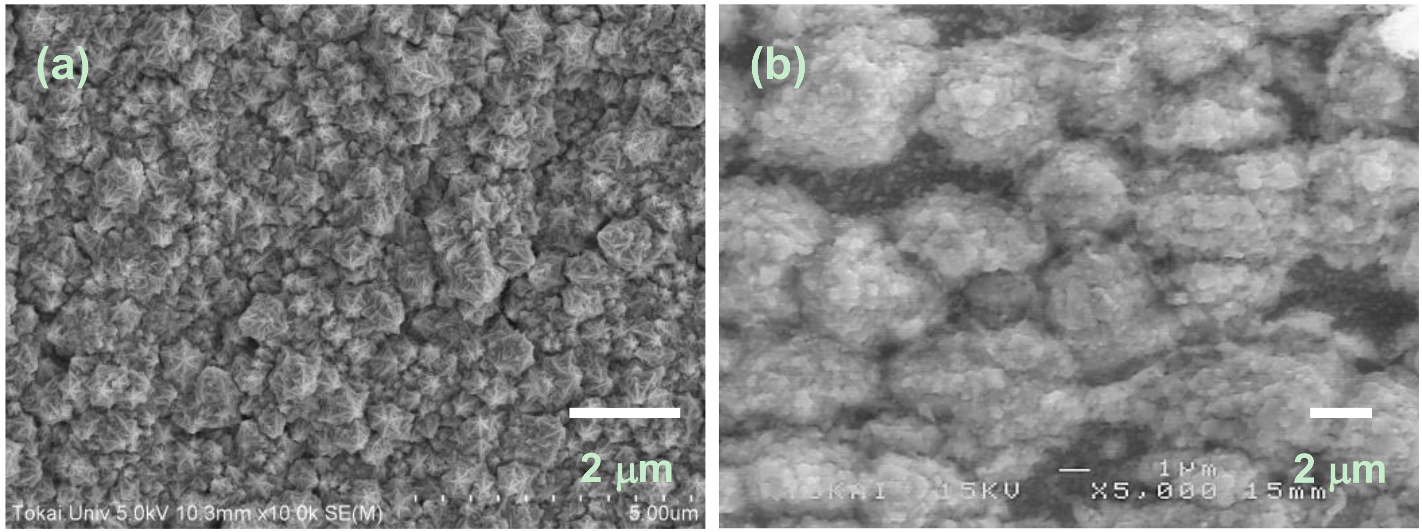
3.1. Thermoelectric and Structual Properties of n-Type Bi2Te3 and p-Type Sb2Te3 Thin Films

Based on our previous study, the conditions of electrodeposition of n-type Bi2Te3 and p-type Sb2Te3 films were determined [39,40]. Table 1 presents the in-plane thermoelectric properties, Seebeck coefficient, electrical conductivity, and power factor of the thin films. The n-type Bi2Te3 thin film exhibited a Seebeck coefficient of −63.0 μV/K, an electrical conductivity of 79.0 S/cm, and a power factor of 0.3 μW/(cm·K2). On the other hand, the p-type Sb2Te3 thin film exhibited a Seebeck coefficient of 172 μV/K, an electrical conductivity of 3.2 S/cm, and a power factor of 0.1 μW/(cm·K2). The thermoelectric properties of both films were lower than that of the corresponding bulk materials [41]. This is because the films exhibited small grains, as shown in SEM images (Figure 1). In our previous reports, we performed the bending test on sputtered Bi2Te3 and Sb2Te3 thin films [16,17]. We found that the surface morphologies of the sputtered films were changed by the bending conditions, but the thermoelectric properties were not greatly changed. Therefore, we considered that the electrodeposited Bi2Te3 and Sb2Te3 thin films in this study would show similar trends. To further increase thermoelectric properties in the future, we plan to carry out not only additional treatments such as thermal annealing [42,43,44] but also investigate the effects of thermal annealing, i.e., the diffusion between the thermoelectric thin films and the stainless-steel substrate, and the cause of micro-cracks in the films during the transfer of thermoelectric thin films to the flexible sheets. After fabricating the flexible thin-film generators, we calculated the electrical resistance of the generators based on the thermoelectric properties of the n- and p-type thin films.

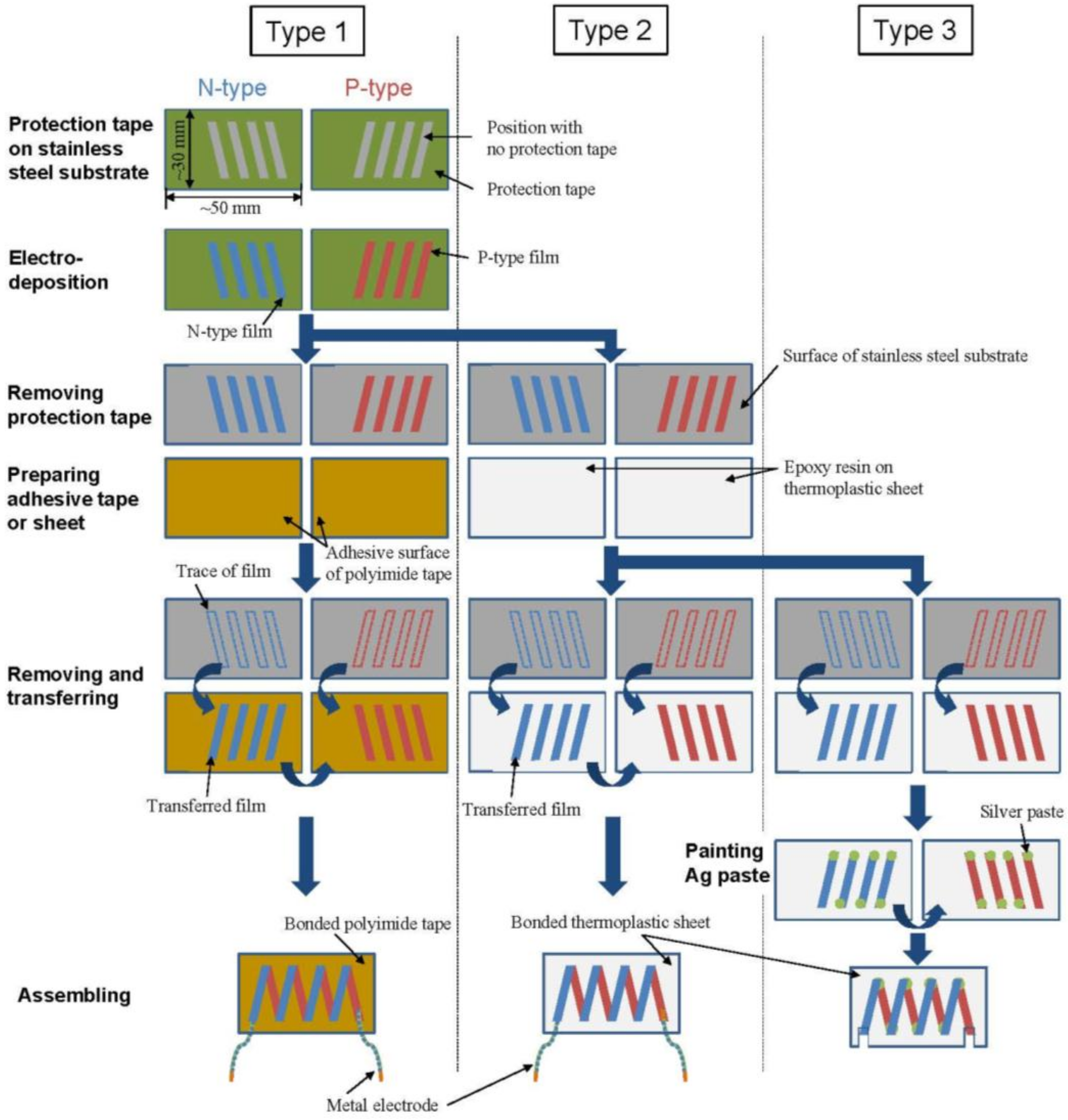
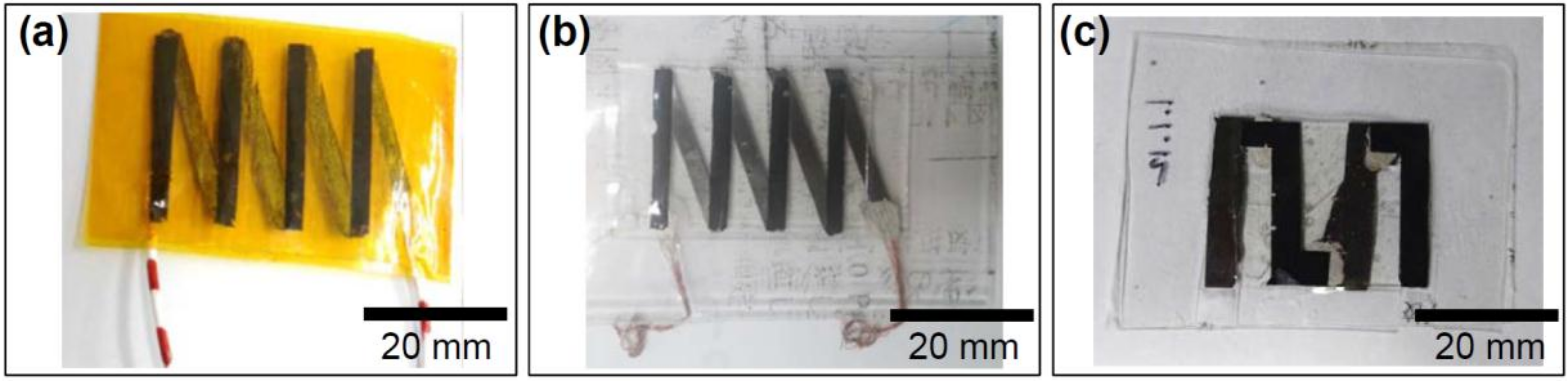
3.2. Fabrication of Flexible Thin-Film Thermoelectric Generators

After determining the electrodeposition conditions of n-type Bi2Te3 and p-type Sb2Te3 thin films, we fabricated the flexible thin-film thermoelectric generators. Figure 2 shows the schematic process flow diagram employed for the fabrication of three thermoelectric generators. For the Type 1 generator, we prepared stainless-steel substrates covered with protection tape, which were partially clipped to achieve rectangle-shaped patterns. The position and shape of the substrate used for the fabrication of the p-type film correspond to those used for the fabrication of the n-type film. The n- and p-type films were electrodeposited on the substrates with thicknesses of 3.1 and 4.1 μm, respectively. The electrodeposition conditions employed for the fabrication of the n- and p-type thin films for the generators were the same as those presented in Section 3.1. After removing the protection tapes from the substrates, only the rectangle-shaped n- and p-type films were left on each stainless steel substrate. Next, the substrate and an adhesive polyimide tape (Kapton® film 650S#25, TERAOKA, Tokyo, Japan) were pasted together and rubbed hard on the tape surface by a finger. When the adhesive polyimide tape was removed from the substrate, the rectangle-shaped films were transferred onto the tape. These rectangle-shaped films were connected together, by electrically connecting the n- and p-type rectangle-shaped films in series. Noted that n–p contacts are not good for the thermoelectric effect because they likely generate a nonlinear resistance effect. To simplify the process flow, we did not insert metals between the n–p contacts. Finally, the generator fabrication was completed by inserting the metal electrodes.
For fabricating the Type 2 generator, the electrodeposition process employed for the Type 1 generator was used. After electrodeposition, the protection tapes were removed from the substrates, and the n- and p-types rectangle-shaped films were then transferred onto a thin epoxy resin (CA-147, CEMEDINE, Tokyo, Japan) partially pasted on thermoplastic sheets (Laminating Film, JOINTEX, Tokyo, Japan). We used epoxy resin instead of the adhesive polyimide tape in the transfer process because the adhesion strength between the films and the epoxy resin is stronger than that between the films and the adhesive polyimide tape. The n- and p-type rectangle-shaped films were connected together when two of the thermoplastic sheets were heat-sealed with a laminating machine while the metal electrodes were inserted.
We fabricated the Type 3 generator by tightly connecting the n- and p-type rectangular films. For fabricating the Type 3 generator, the same process employing the electrodeposition and the transfer process as that used for the Type 2 generator was employed. After the transfer process, silver pastes were painted on both ends of the n- and p-type rectangle-shaped films. The n- and p-type films were connected together, and the silver paste was then air-dried. Two of the thermoplastic sheets were heat-sealed using a laminating machine.
Figure 3 shows the photographs of three types of flexible thin-film thermoelectric generators. The Type 1 generator (Figure 3a) was composed of four pairs of n- and p-type films with a length of 30 mm and a width of 3 mm. The generator fabricated with the thin films was 40 mm wide, 30 mm high, and 60 μm thick. As shown in Figure 3b, the configuration of the Type 2 generator was mostly the same as that of Type 1 generator except for the use of thermoplastic sheets and the thickness of 0.6 mm. The thickness of the Type 2 generator was 10 times higher than that of the Type 1 generator, but the Type 2 generator also exhibited flexibility. As shown in Figure 3c, the Type 3 generator was composed of two pairs of n- and p-type films, and each rectangle-shaped film was 25 mm long and 4.5 mm wide, different from films prepared in the Type 1 and Type 2 generators. This is because we tried several times to fabricate the Type 3 generator with the same layout as that of the Type 2 generator. However, those trials ended in failure because some films broke during the process. Therefore, in order to firstly complete the generators using the combination processes with a well conducting current, we reduced the number of films and the film width was extended. The Type 3 generator was 35 mm wide and 25 mm high. The thickness of the Type 3 generator was 0.6 mm, which is the same as that of the Type 2 generator. In the Type 3 generator, the metal electrodes were not inserted, but both ends of the rectangle-shaped films were exposed to air by removing the corresponding part of the thermoplastic sheets.

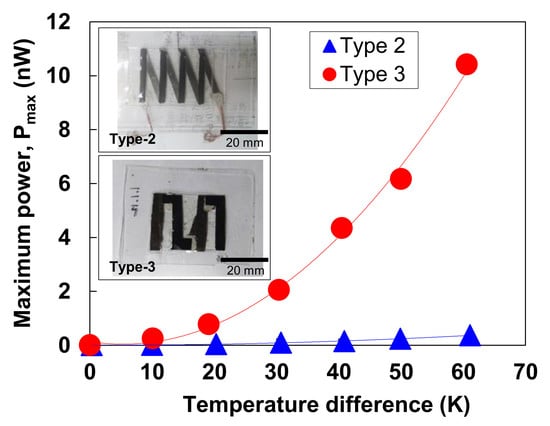
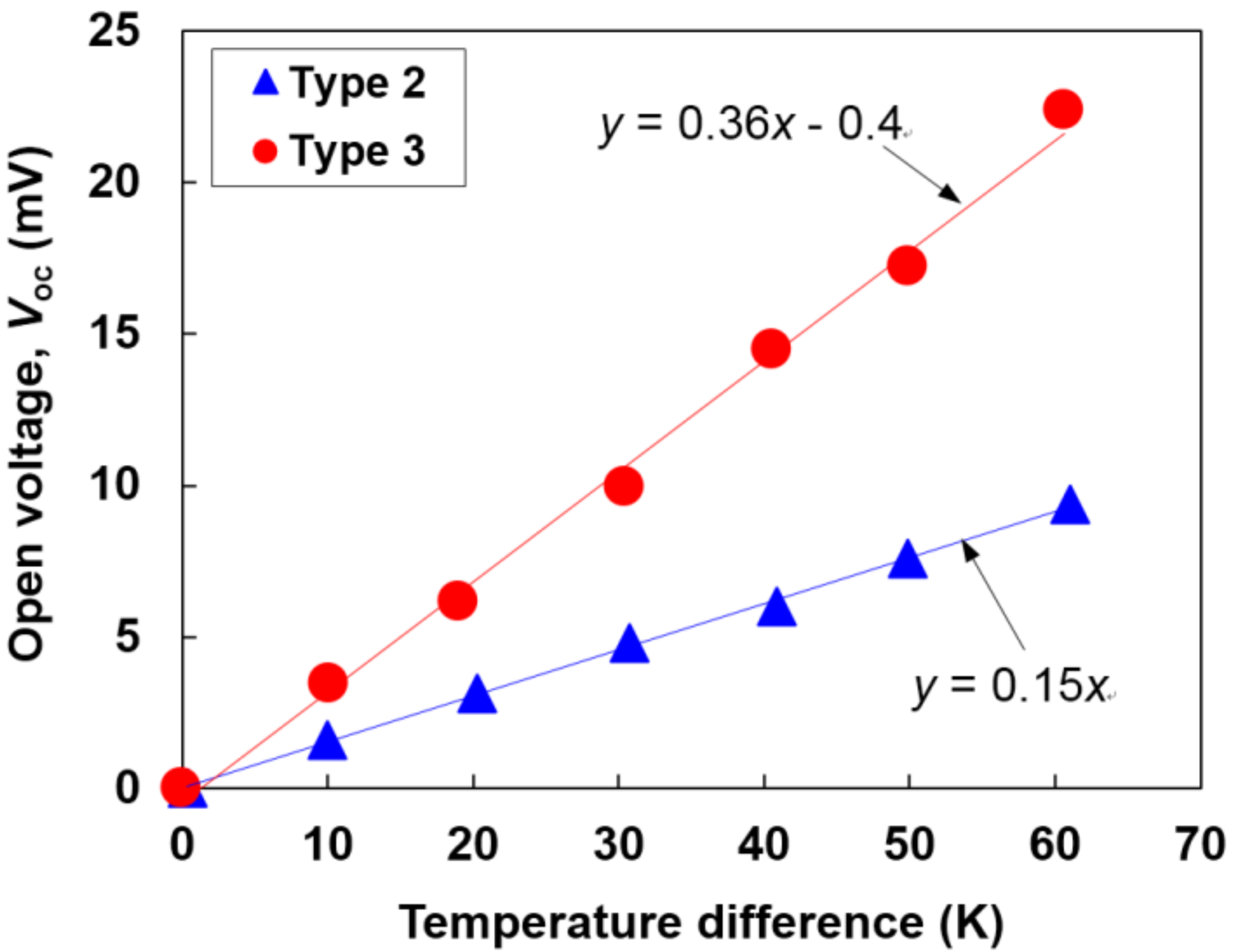
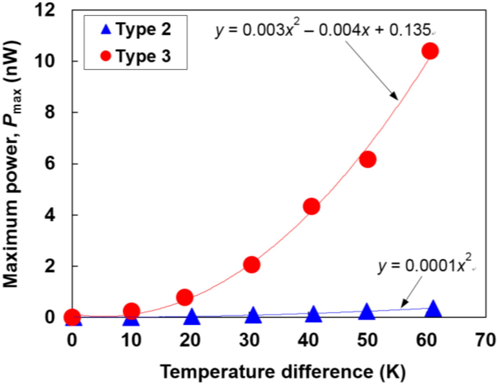
3.3. Performance of Flexible Thin-Film Thermoelectric Generators

We initially measured the total resistance (Rtotal) of the flexible thin-film thermoelectric generators, as listed in Table 2. The Rtotal value of the Type 1 generator was not measured because the rectangle-shaped thin films were partially broken during the transfer process. When the thin films were removed from the substrate, adhesive polyimide tape was extremely bent with the stretching state. As a result, micro-cracks appeared in the thin films, leading to partial breaking.
The Type 2 generator exhibited an Rtotal of 60 kΩ. Based on the measured electrical conductivity of n- and p-type thin films as listed in Table 1 and the film sizes as described in Section 3.2, the resistance for only the films (Rfilm) in the Type 2 generator was expected to be 31 kΩ. As a result, the Rtotal value in the Type 2 generator was approximately two times higher than the Rfilm value in the Type 2 generator, indicating that the Type 2 generator exhibited a relatively high contact resistance (Rcont) of 29 kΩ at the junctions between the n- and p-type thin films. On the other hand, the measured Rtotal in the Type 3 generator was 12 kΩ, and Rfilm was expected to be 8.6 kΩ. As a result, Rcont was estimated to be 3.4 kΩ, significantly lower than that obtained with the Type 2 generator because the junctions between n- and p-type films in the Type 3 generator were tightly connected using the silver paste, and the number of junctions was low.
To measure the performance of the flexible thin-film thermoelectric generators, a temperature difference was applied between the ends of the generators. The temperatures on both sides were monitored using the thermocouples (K-type) attached to the generator. In this study, we put the temperature difference at a maximum of 60 K, and it was difficult to further increase the temperature difference because the temperature of the cold side increased due to the thermal conduction from the hot side. When a temperature difference was generated, the open circuit voltage (Voc) was measured using a digital multi-meter (TakedaRiken, Tokyo, Japan, TR6841). The Voc of the flexible thin-film thermoelectric generators as a function of temperature difference is shown in Figure 4. We here confirmed that the relationship between the Voc and temperature difference obtained reproducibility and reliability for repetitive operations. The results obtained for the Type 1 generator are not presented in this figure because Voc was not measured owing to the partial breaking of the films. The Voc value of the Type 2 and Type 3 generators increased as the temperature difference was increased. At a temperature difference of 60 K, the Voc values of the Type 2 and Type 3 generators were 9.4 and 22.4 mV, respectively. The Voc value of the Type 3 generator was 2.4 times higher than that of the Type 2 generator even though the number of the n–p pairs in the Type 3 generator was smaller than that in the Type 2 generator. This is because the higher resistance, which includes the film resistance and contact resistance, of the Type 2 generator caused a larger voltage drop as compared to that in the Type 3 generator. We conclude that the contact resistance is responsible for the voltage drop, based on our preliminarily experiment. In the preliminarily experiment, we prepared the Type 2 generator with the same layout as the Type 3 generator but without Ag paste connection and measured the output voltage. As a result, the voltage of the generator prepared in the preliminarily experiment decreased compared to those of the Type 2 and Type 3 generators.
The maximum output power (Pmax) of the flexible thin-film thermoelectric generators as a function of the temperature difference is shown in Figure 5. The Pmax is expressed as Pmax = Voc2/4Rtotal, and the accuracy of measurement was approximately ±10%. In the Type 2 generator, Pmax was estimated to be 0.4 nW at a temperature difference of 60 K. On the other hand, the Pmax value of the Type 3 generator drastically improved. Pmax increased exponentially with an increase in the temperature difference. At a temperature difference of 60 K, the Pmax of the Type 3 generator was 10.4 nW, which is 26 times higher than that of the Type 2 generator. Therefore, the performance of flexible thin-film thermoelectric generators can be improved to reduce the contact resistance, but the performance was still low compared to that of the generators fabricated using dry processing [4,6,45] and was not sufficient to operate potential applications such as CMOS image sensors [46], so there is room for improvement. However, we demonstrated the successful fabrication of flexible thin-film generators, which were obtained by the combination of electrodeposition and transfer processes, and this technology suggests the possible benefits of fabricating flexible thin-film generators at a low manufacturing cost.

4. Conclusions

We fabricated three types of flexible thin-film thermoelectric generators, which consisted of n-type Bi2Te3 films and p-type Sb2Te3 films, using a combination of electrodeposition and transfer processes. Electrodeposition was performed on a stainless-steel substrate using potentiostatic electrodeposition with nitric acid based bathes. The transfer process was performed using adhesive polyimide tapes or thermoplastic sheets with epoxy resin. The open circuit voltage (Voc) and maximum output power (Pmax) were measured by applying a temperature difference between the ends of the generator. The best generator obtained in this study exhibited a Pmax of 10.4 nW at a temperature difference of 60 K. The performance of the thin-film generators improved, with a decrease in the number of micro-cracks in the thin films and on achieving a tight connection between the n- and p-type films using silver pastes. The current performance of the generators was too low, but we innovated the combination process to prepare the thin-film generators.

Acknowledgements

This study was partly supported by JSPS KAKENHI Grant Number 16K06752. The authors wish to thank Michael Faudree, Mitsuaki Okuhata, Momoko Takahashi, Takumi Makioka, Masaki Yamaguchi, Yuki Kimura, Akihiro Kobayashi, Kosuke Takano, Ken Hagiwara, and Akito Kawahira at Tokai University for experimental support.

Author Contributions

Hiroki Yamamuro and Masayuki Takashiri conceived and designed the experiments; Naoki Hatsuta, Makoto Wachi and Yoshihiro Takei performed the experiments; Naoki Hatsuta, Makoto Wachi and Yoshihiro Takei analyzed the data; Hiroki Yamamuro contributed reagents/materials/analysis tools; Hiroki Yamamuro and Masayuki Takashiri wrote the paper.

Conflicts of Interest

The authors declare no conflict of interest.

References

  1. Beeby, S.P.; Tudor, M.J.; White, N.M. Energy harvesting vibration sources for microsystems applications. Meas. Sci. Technol. 2006, 17, R175–R195. [Google Scholar] [CrossRef]
  2. Paradiso, J.A.; Starner, T. Energy scavenging for mobile and wireless electronics. IEEE Pervasive Comput. 2005, 4, 18–27. [Google Scholar] [CrossRef]
  3. Kulah, H.; Najafi, K. Energy Scavenging from low-frequency vibrations by using frequency up-conversion for wireless sensor applications. IEEE Sens. J. 2008, 8, 261–268. [Google Scholar] [CrossRef]
  4. Takayama, K.; Takashiri, M. Multi-layered-stack thermoelectric generators using p-type Sb2Te3 and n-type Bi2Te3 thin films by radio-frequency magnetron sputtering. Vacuum 2017, 144, 164–171. [Google Scholar] [CrossRef]
  5. Kurosaki, J.; Yamamoto, A.; Tanaka, S.; Cannon, J.; Miyazaki, K.; Tsukamoto, H. Fabrication and evaluation of a thermoelectric microdevice on a free-standing substrate. J. Electron. Mater. 2009, 38, 1326–1330. [Google Scholar] [CrossRef]
  6. Mizoshiri, M.; Mikami, M.; Ozaki, K. p-Type Sb2Te3 and n-Type Bi2Te3 films for thermoelectric modules deposited by thermally assisted sputtering method. Jpn. J. Appl. Phys. 2013, 52, 06GL07. [Google Scholar] [CrossRef]
  7. Chen, X.; Xu, S.; Yao, N.; Shi, Y. 1.6 V nanogenerator for mechanical energy harvesting using PZT nanofibers. Nano Lett. 2010, 10, 2133–2137. [Google Scholar] [CrossRef] [PubMed]
  8. Zhang, H.; Yang, Y.; Hou, T.C.; Su, Y.; Hu, C.; Wang, Z.L. Triboelectric nanogenerator built inside clothes for self-powered glucose biosensors. Nano Energy 2013, 2, 1019–1024. [Google Scholar] [CrossRef]
  9. Francioso, L.; Pascali, C.D.; Farella, I.; Martucci, C.; Cretì, P.; Siciliano, P.; Perrone, A. Flexible thermoelectric generator for ambient assisted living wearable biometric sensors. J. Power Sources 2011, 196, 3239–3243. [Google Scholar] [CrossRef]
  10. Fan, P.; Zheng, Z.; Li, Y.; Lin, Q.; Luo, J.; Liang, G.; Cai, X.; Zhang, D.; Ye, F. Low-cost flexible thin-film thermoelectric generator on zinc based thermoelectric materials. Appl. Phys. Lett. 2015, 106, 073901. [Google Scholar] [CrossRef]
  11. Zhu, W.; Deng, Y.; Cao, L. Light-concentrated solar generator and sensor based on flexible thin-film thermoelectric device. Nano Energy 2017, 34, 463–471. [Google Scholar] [CrossRef]
  12. Zhao, D.; Min, Z. Enhanced thermoelectric performance of Ga-added Bi0.5Sb1.5Te3 films by flash evaporation. Intermetallics 2012, 31, 321–324. [Google Scholar] [CrossRef]
  13. Takashiri, M.; Tanaka, S.; Miyazaki, K. Determination of the origin of crystal orientation for nanocrystalline bismuth telluride-based thin films prepared by use of the flash evaporation method. J. Electron. Mater. 2014, 43, 1881–1889. [Google Scholar] [CrossRef]
  14. Takashiri, M.; Imai, K.; Uyama, M.; Hagino, H.; Tanaka, S.; Miyazaki, K.; Nishi, Y. Comparison of crystal growth and thermoelectric properties of n-type Bi-Se-Te and p-type Bi-Sb-Te nanocrystalline thin films: Effects of homogeneous irradiation with an electron beam. J. Appl. Phys. 2014, 115, 214311. [Google Scholar] [CrossRef]
  15. Böttner, H.; Nurnus, J.; Gavrikov, A.; Kühner, G.; Jägle, M.; Kunzel, C.; Eberhard, D.; Plescher, G.; Schubert, A.; Schlereth, K.H. New thermoelectric components using microsystem technologies. J. Microelectromech. Syst. 2004, 13, 414–420. [Google Scholar] [CrossRef]
  16. Kusagaya, K.; Takashiri, M. Investigation of the effects of compressive and tensile strain on n-type bismuth telluride and p-type antimony telluride nanocrystalline thin films for use in flexible thermoelectric generators. J. Alloy. Compd. 2015, 653, 480–485. [Google Scholar] [CrossRef]
  17. Kusagaya, K.; Hagino, H.; Tanaka, S.; Miyazaki, K.; Takashiri, M. Structural and thermoelectric properties of nanocrystalline bismuth telluride thin films under compressive and tensile strain. J. Electron. Mater. 2015, 44, 1632–1636. [Google Scholar] [CrossRef]
  18. Snyder, G.J.; Lim, J.R.; Huang, C.; Fleurial, J. Thermoelectric microdevice fabricated by a MEMS-like electrochemical process. Nat. Mater. 2003, 2, 528–531. [Google Scholar] [CrossRef] [PubMed]
  19. Matsuoka, K.; Okuhata, M.; Takashiri, M. Dual-bath electrodeposition of n-type Bi-Te/Bi-Se multilayer thin films. J. Alloy. Compd. 2015, 649, 721–725. [Google Scholar] [CrossRef]
  20. Venkatasubramanian, R.; Siivola, E.; Colpitts, T.; O’Quinn, B. Thin-film thermoelectric devices with high room-temperature figures of merit. Nature 2001, 413, 597–602. [Google Scholar] [CrossRef] [PubMed]
  21. Harman, T.C.; Taylor, P.J.; Walsh, M.P.; LaForge, B.E. Quantum dot superlattice thermoelectric materials and devices. Science 2002, 297, 2229–2232. [Google Scholar] [CrossRef] [PubMed]
  22. Zhang, Y.; Chen, Y.; Gong, C.; Yang, J.; Qian, R.; Wang, Y. Optimization of superlattice thermoelectric materials and microcoolers. J. Microelectromech. Syst. 2007, 16, 1113–1119. [Google Scholar] [CrossRef]
  23. Poudel, B.; Hao, Q.; Ma, Y.; Lan, Y.; Minnich, A.; Yu, B.; Yan, X.; Wang, D.; Muto, A.; Vashaee, D.; et al. High-thermoelectric performance of nanostructured bismuth antimony telluride bulk alloys. Science 2008, 320, 634–638. [Google Scholar] [CrossRef] [PubMed]
  24. Yamauchi, K.; Takashiri, M. Highly oriented crystal growth of nanocrystalline bismuth telluride thin films with anisotropic thermoelectric properties using two-step treatment. J. Alloy. Compd. 2017, 698, 977–983. [Google Scholar] [CrossRef]
  25. Kudo, S.; Hagino, H.; Tanaka, S.; Miyazaki, K.; Takashiri, M. Determining the thermal conductivities of nanocrystalline bismuth telluride thin films using the differential 3ω method while accounting for thermal contact resistance. J. Electron. Mater. 2015, 44, 2021–2025. [Google Scholar] [CrossRef]
  26. Lee, J.; Galli, G.A.; Grossman, J.C. Nanoporous Si as an efficient thermoelectric material. Nano Lett. 2008, 8, 3750–3754. [Google Scholar] [CrossRef] [PubMed]
  27. Kashiwagi, M.; Hirata, S.; Harada, K.; Zheng, Y.; Miyazaki, K.; Yahiro, M.; Adachi, C. Enhanced figure of merit of a porous thin film of bismuth antimony telluride. Appl. Phys. Lett. 2011, 98, 023114. [Google Scholar] [CrossRef]
  28. Takashiri, M.; Tanaka, S.; Hagino, H.; Miyazaki, K. Combined effect of nanoscale grain size and porosity on lattice thermal conductivity of bismuth-telluride-based bulk alloys. J. Appl. Phys. 2012, 112, 084315. [Google Scholar] [CrossRef]
  29. Biswas, K.; He, J.; Zhang, Q.; Wang, G.; Uher, C.; Dravid, V.P.; Kanatzidis, M.G. Strained endotaxial nanostructures with high thermoelectric figure of merit. Nat. Chem. 2011, 3, 160–166. [Google Scholar] [CrossRef] [PubMed]
  30. Inamoto, T.; Takashiri, M. Experimental and first-principles study of the electronic transport properties of strained Bi2Te3 thin films on a flexible substrate. J. Appl. Phys. 2016, 120, 125105. [Google Scholar] [CrossRef]
  31. Inamoto, T.; Morikawa, S.; Takashiri, M. Combined infrared spectroscopy and first-principles calculation analysis of electronic transport properties in nanocrystalline Bi2Te3 thin films with controlled strain. J. Alloys Compd. 2017, 702, 229–235. [Google Scholar] [CrossRef]
  32. Frantz, C.; Stein, N.; Zhang, Y.; Bouzy, E.; Picht, O.; Toimil-Molares, M.E.; Boulanger, C. Electrodeposition of bismuth telluride nanowires with controlled composition in polycarbonate membranes. Electrochim. Acta 2012, 69, 30–37. [Google Scholar] [CrossRef]
  33. Xiao, F.; Hangarter, C.; Yoo, B.; Rheem, Y.; Lee, K.H.; Myung, N.V. Recent progress in electrodeposition of thermoelectric thin films and nanostructures. Electrochim. Acta 2008, 53, 8103–8117. [Google Scholar] [CrossRef]
  34. Manzano, C.V.; Abad, B.; Rojo, M.M.; Borca-Tasciuc, T.; Gonzalez, M.M. Anisotropic effects on the thermoelectric properties of highly oriented electrodeposited Bi2Te3 films. Sci. Rep. 2016, 6, 19129. [Google Scholar] [CrossRef] [PubMed] [Green Version]
  35. Ye, Y.; Mao, Y.; Wang, F.; Lu, H.; Qu, L.; Dai, L. Solvent-free functionalization and transfer of aligned carbon nanotubes with vapor-deposited polymer nanocoatings. J. Mater. Chem. 2011, 21, 837–842. [Google Scholar] [CrossRef]
  36. Bell, L.E. Cooling, heating, generating power, and recovering waste heat with thermoelectric systems. Science 2008, 321, 1457–1461. [Google Scholar] [CrossRef] [PubMed]
  37. Matsuoka, K.; Okuhata, M.; Hatsuta, N.; Takashiri, M. Effect of composition on the properties of bismuth telluride thin films produced by galvanostatic electrodeposition. Trans. Mater. Res. Soc. Jpn. 2015, 40, 383–387. [Google Scholar] [CrossRef]
  38. Okuhata, M.; Takemori, D.; Takashiri, M. Effect of pulse frequency on structural and thermoelectric properties of bismuth telluride thin films by electrodeposition. ECS Trans. 2017, 75, 133–141. [Google Scholar] [CrossRef]
  39. Takemori, D.; Okuhata, M.; Takashiri, M. Thermoelectric properties of electrodeposited bismuth telluride thin films by thermal annealing and homogeneous electron beam irradiation. ECS Trans. 2017, 75, 123–131. [Google Scholar] [CrossRef]
  40. Hatsuta, N.; Takemori, D.; Takashiri, M. Effect of thermal annealing on the structural and thermoelectric properties of electrodeposited antimony telluride thin films. J. Alloy. Compd. 2016, 685, 147–152. [Google Scholar] [CrossRef]
  41. Scherrer, H.; Scherrer, S. Thermoelectric Materials. In CRC Handbook of Thermoelectrics; Rowe, D.M., Ed.; CRC Press: New York, NY, USA, 1995; pp. 211–237. [Google Scholar]
  42. Takashiri, M.; Kurita, K.; Hagino, H.; Tanaka, S.; Miyazaki, K. Enhanced thermoelectric properties of phase-separating bismuth selenium telluride thin films via a two-step method. J. Appl. Phys. 2015, 118, 065301. [Google Scholar] [CrossRef]
  43. Takashiri, M.; Asai, Y.; Yamauchi, K. Structural, optical, and transport properties of nanocrystalline bismuth telluride thin films treated with homogeneous electron beam irradiation and thermal annealing. Nanotechnology 2016, 27, 335703. [Google Scholar] [CrossRef] [PubMed]
  44. Kudo, S.; Tanaka, S.; Miyazaki, K.; Nishi, Y.; Takashiri, M. Anisotropic analysis of nanocrystalline bismuth telluride thin films treated by homogeneous electron beam irradiation. Mater. Trans. 2017, 58, 513–519. [Google Scholar] [CrossRef]
  45. Fan, P.; Zheng, Z.; Cai, Z.; Chen, T.; Liu, P.; Cai, X.; Zhang, D.; Liang, G.; Luo, J. The high performance of a thin-film thermoelectric generator with heat flow running parallel to film surface. Appl. Phys. Lett. 2013, 102, 033904. [Google Scholar] [CrossRef]
  46. Hanson, S.; Seok, M.; Lin, Y.S.; Foo, Z.Y.; Kim, D.; Lee, Y.; Liu, N.; Ylvester, S.D.; Blaauw, D. A Low-voltage processor for sensing applications with picowatt standby mode. IEEE J. Solid-State Circuits 2010, 45, 759–767. [Google Scholar] [CrossRef]
Figure 1. SEM images of the surface morphology and grain structure of (a) Bi2Te3 and (b) Sb2Te3 thin films.
Coatings 08 00022 g001
Figure 2. Schematic process flow diagram of the three types of flexible thin-film thermoelectric generators.
Coatings 08 00022 g002
Figure 3. Photographs of the three types of flexible thin-film thermoelectric generators. (a) Type 1; (b) Type 2; (c) Type 3.
Coatings 08 00022 g003
Figure 4. Open circuit voltage (Voc) of the flexible thin-film thermoelectric generators as a function of temperature difference.
Coatings 08 00022 g004
Figure 5. Maximum power (Pmax) of the flexible thin-film thermoelectric generators as a function of temperature difference.
Coatings 08 00022 g005
Table 1. In-plane thermoelectric properties of the n- and p-type thin films.
Column TitleS (μV/K)σ (S/cm)Power Factor, S2σ (μW/(cm·K2))
n-type film−62.8790.3
p-type film172.33.20.1
Table 2. Total electrical resistance of the flexible thin-film generators.
Type of GeneratorRtotal (kΩ)
Type 1N/A
Type 20
Type 312

