Article

Titanium Aluminium Nitride and Titanium Boride Multilayer Coatings Designed to Combat Tool Wear

1
School of Aerospace, Transport and Manufacturing, Surface Engineering and Nanotechnology Institute (SENTi), Cranfield University, Cranfield MK43 0AL, UK
2
Senior Manager (Development) Hindustan Aeronautics Limited Foundry and Forge Division Old Airport Road, PB No. 1791, Bangalore 560017, India
*
Author to whom correspondence should be addressed.
Coatings 2018, 8(1), 12; https://doi.org/10.3390/coatings8010012
Submission received: 17 November 2017 / Revised: 13 December 2017 / Accepted: 21 December 2017 / Published: 28 December 2017
(This article belongs to the Special Issue Coatings for Cutting Tools)

Abstract

:
The lifetimes and the premature wear of machining tools impact on manufacturing efficiencies and productivities. A significant proportion of machining tool damage can be attributed to component wear. Here, titanium aluminium nitride (TiAlN) multi-layered with titanium diboride (TiB2) prepared by PVD (Physical Vapour Deposition) sputtering onto H-13 substrates are studied as potential wear-resistant coatings for forging die applications. The TiB2 content has been altered and two-sets of coating systems with a bilayer thickness either less than or greater than 1 μm are investigated by tribological and microstructural analysis. XRD analysis of the multilayers reveals the coatings to be predominately dominated by the TiAlN (200) peak, with additional peaks of TiN (200) and Ti (101) at a TiB2 content of 9%. Progressive loads increasing to 100 N enabled the friction coefficients and the coating failure at a critical load to be determined. Friction coefficients of around 0.2 have been measured in a coating containing 9% TiB2 at critical loads of approximately 70 N. Bi-directional wear tests reveal that bilayers with thicknesses greater than 1 μm have frictional coefficients that are approximately 50% lower than those where the bilayer is less than 1 μm. This is due to the greater ability of thicker bilayers to uniformly distribute the stress within the layers. There are two observed frictional coefficient regimes corresponding to a lower and higher rate of material loss. At the lower regime, with TiB2 contents below 20%, material loss occurs mainly via delamination between the layers, whilst at compositions above this, material loss occurs via a break-up of material into finer particles that in combination with the higher loads results in greater material loss. The measured wear scar volumes for the TiAlN/TiB2 multilayer coatings are approximately three times lower than those measured on the substrate, thus validating the increased wear resistance offered by these composite coatings.

1. Introduction

The lifetimes and the premature wear of forging dies and other machining tools impact on manufacturing efficiencies and product qualities. More than half of machining tool damage can be attributed to component wear with potential downtimes affecting productivity [1,2]. The demand to improve the tribological characteristics of machining tools using coatings is therefore considered to be an efficient and cost-effective proposition. The application of surface treatments preventing premature wear has been around for many years with the development of coatings such as TiC or CrN coatings that typically form a B1-type or tetragonal structure, exhibiting excellent mechanical strengths and high melting points in addition to superior wear resistance [3,4]. Important determinants affecting the performance of any type of coating comprise a combination of factors that include the adhesion of the coating to its substrate, the coating microstructure, the hardness, and the coating lubricity which determines sliding contact forces [5,6]. From the development of single-layer coating systems, the design of two or more nano-structured layers forming a composite or hybrid coating have evolved, a so-called multilayer coating, combining the physical characteristics of two or more materials. Multilayer coatings offering, for example, both hard and lubricious properties are reported [7,8] and have now become the standard adopted by the industry [9,10,11].
Titanium aluminium nitride (TiAlN) is employed in dry machining applications mainly due to its high hardness, oxidation resistance and micro-abrasive wear resistant properties [12,13]. It is exceptionally suited to forging die applications where during operation, the die experiences severe thermal and mechanical shocks and surface temperatures can also rapidly exceed 500 °C. These repeated mechanical and thermal stress cycles promote rapid tool wear [14]. It is reported that the addition of boron in the Ti-Al material system improves its wear characteristics due to the formation of TiB2 and boron nitride (BN) [15]. Boron nitride also offers superior characteristics in terms of high heat capacities and thermal conductivities and offers lubricity even in dry environments [16]. Titanium diboride (TiB2) offers high temperature oxidation protection due to its high melting point (3490 K), thermal stability [17] and high strength to density ratio. Moreover, TiB2 offers high hardness, superior Young’s modulus and abrasive wear resistance, being particularly suited for machine tooling applications [18]. Nano-structured multilayer coatings based on TiAlN have superior thermal stabilities, greater hardness and offer exceptional wear resistance characteristics surmounting that of a composite TiAlN coating [19]. Therefore, it is proposed that multilayers of TiAlN and TiB2 will yield a hybrid coating offering superior mechanical, metallurgical and tribological properties, allowing deployment in complex and demanding wear conditions [20,21,22]. Therefore, a multilayer coating comprising both TiAlN and TiB2 offers an interesting perspective to prevent the premature wear of forging dies or other machining tools. H-13 is a popular tool steel comprising Cr, Mo and V and giving rise to high hardness and toughness properties. The adhesion, hardness and microstructure of multilayer coatings of TiAlN/TiB2 deposited by PVD sputtering onto H-13 tool steel are investigated. The incorporation of high amounts of B is of particular interest since it potentially offers greater wear-resistant properties, as reported in the literature [15]. A further consideration when designing multilayer systems is the stress generated within the coating, governed by the bilayer thickness and defined as the sum of the individual layer thicknesses. Previous studies indicate that the bilayer thickness in multilayer systems has an important influence on wear behaviour [18,19] and the addition of small amounts of TiB2 has proved to enhance the mechanical characteristics [8,23]. Therefore, the objectives of the study are to characterise the wear properties of multilayer coatings with different TiB2 contents and two sets of bilayer thicknesses.

2. Material and Methods

2.1. Substrate Preparation

The measured hardness of the as-received H-13 substrate material was 270 HV ± 10 HV (2.7 GPa), indicating that the material had been prior-annealed. H-13 is a standard tool steel employed by the industry comprising 5 wt % Cr, 1.3 wt % molybdenum and 1 wt % vanadium and silicon. An important aspect in any coatings design and for the development of cutting tools is the coating adhesion to its substrate [24]. To improve coating adhesion, the samples underwent a two-step heating process comprising a hardening stage followed by a tempering process. The hardening stage involved heating the samples to 1030 °C ± 10 °C and leaving them to soak for 45 min before cooling in air. Tempering was a two-stage process—heating to 570 °C ± 10 °C and soaking for 2 h and then cooling in air to improve toughness and ductility [25]. This process was repeated to ensure that a constant microstructure and hardness would be achieved. The measured surface hardness was around 540 HV (5.3 GPa). The samples were then grit-blasted to remove any oxides formed during the heat treatment process. To further enhance the mechanical characteristics of the near-surface region, the substrate material underwent a double-stage nitriding process. Nitriding can lead to the formation of a white layer, an undesirable brittle layer that causes coating spallation, and therefore, the formation of this layer has to be minimised. Nitriding involved heating the sample to temperatures 500–550 °C ± 10 °C for a total of 25 h. The white layer after nitriding was measured to be 25 μm and was removed by a surface grinding operation. The surface hardness after this step was measured to be 1100–1150 HV (10.8–11.3 GPa). Prior to deposition, the substrates were ultrasonically cleaned for 30 min in acetone and for 20 min in isopropyl alcohol.

2.2. Sputtering

The coatings were prepared in a Leybold L560 PVD sputtering machine (Leybold, Chessington, UK) equipped with two magnetrons powered by a dual-output Advanced Energy Pinnacle® (West Sussex, UK) pulsed DC supply. The pulsed DC frequency was set to 220 kHz and a pulse time of 1.1 μs, and to 150 kHz at a pulse time of 2 μs for the TiAlN and TiB2 depositions, respectively. The chamber was turbo-pumped to a base pressure better than 10−6 mbar prior to deposition. TiAlN was reactively co-sputtered in an Ar + N2 gas atmosphere using a Ti target (7.5 cm diameter) with a purity of 99.95%. A number of 15 mm diameter Al discs placed on the magnetron wear track of the target allowed stoichiometric control of the TiAlN coatings. TiB2 was deposited from a 99.95% pure (7.5 cm diameter) target in an Ar atmosphere. A series of monoloyer coatings were first deposited in different concentrations of N2 ranging between 20% and 40%. Sputtering power densities ranged between 3.5 W/cm2 and 5.3 W/cm2 with measured deposition rates of 0.4–0.65 μm/h. All depositions were performed at a pressure of 1 × 10⁻² bar. Before deposition, an in-situ high-bias substrate clean at a voltage of −550 V was undertaken to remove any trace surface contamination. For the multilayer coatings, a 0.3–0.5 μm TiAl strike layer was deposited on the substrate surface to promote adhesion. The substrate table was grounded during the remainder of the deposition.

2.3. Design of the Multilayer Coatings

The multilayer coating design principle adopted here enables the constituent content to be altered by changing the thickness of either the TiAlN or TiB2 layers, for a given bilayer thickness (λ). Here, the λ is defined as the sum of the two layers namely, TTiB2 and TTiAlN, corresponding to the thickness of the metal-ceramic and the nitride layers, respectively.
λ = T TiB 2 + T TiAlN
The % of TiB2 in the coating (VP) is calculated according to:
V P ( % ) = T TiB 2 ( T TiB 2 + T TiAlN ) × 100
By modifying the power to the TiB2 magnetron, layered coatings with VP ranging between 9% and 50% were fabricated with a λ value ranging between 0.3 μm and 2.7 μm. The total coating thickness was between 5 μm and 18 μm and realised by varying the bilayer thickness.

2.4. XRD Characterisation

The coating crystallinity and the constituent phases formed at room temperature were determined by X-ray diffraction using a Cu-kα source operating at 40 kV and 30 mA and at a wavelength of 1.542 Å. The depth of penetration into the film will depend on the acceleration voltage and density of the material, but is between 1 μm and 3 μm. A plot of the hkl Miller planes was obtained over a 2θ between 20° and 70° at a speed of 1° min−1. This speed was chosen so as to obtain a high-resolution spectrum. The resulting constituent phases formed in the TiAlN and TiB2 layers were compared with the standard values of Ti, TiN, TiB2 and TiAlN obtained from the JCPDS database.

2.5. Laser Confocal Microscope

A 3D-image of the surface was obtained using an Olympus LEXT OLS3100 (Hamburg, Germany) confocal microscope. After wear studies, from the image, it was possible to measure the length, width and depth of the wear scars allowing a quantitative analysis of coating behaviour to be made.

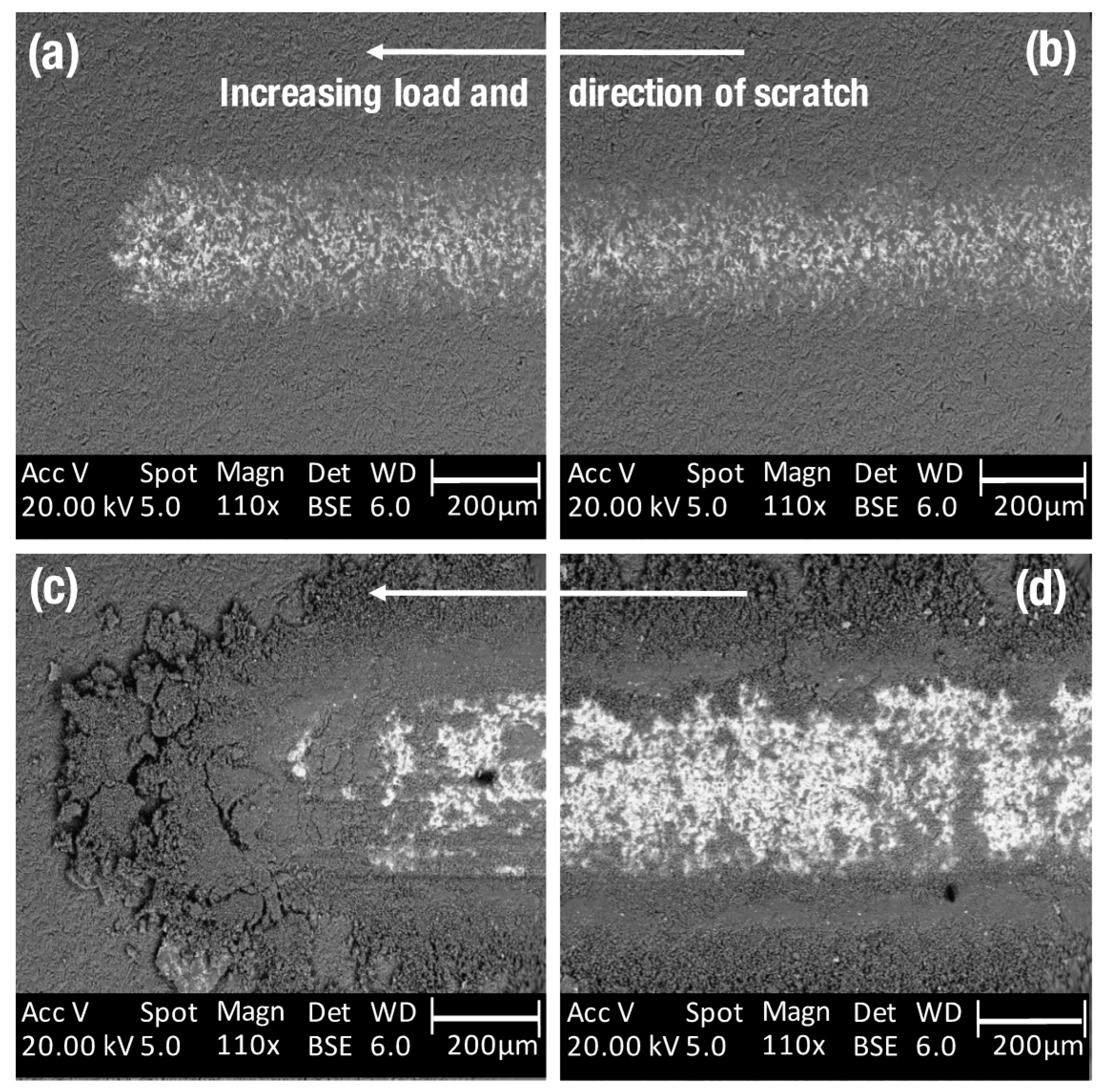
2.6. Scratch and Wear Tests

The tribological properties of the coatings were evaluated employing a Teer ST3001 Scratch Tester® (Teer, Droitwich, UK) operated in one of two modes—a “progressive load” mode where a 5 mm diameter tungsten carbide ball is used to indent the coatings with increasing loads between 5 N and 100 N, allowing the critical load (LC) to be determined and from that the friction coefficient (μ) calculated; or in a “constant load” mode where the wear characteristics are evaluated over a number of cycles at a given constant load. LC is the smallest load at which the coating first begins to fail and serves as a quantitative value of the coating adhesion, identified by monitoring an acoustic signal emanating from the film surface. The friction coefficients are obtained by dividing the instantaneous friction by the given load according to the expression μ = F/L, where F is the measured friction and L is the instantaneous measured load. Coating failure at the critical load manifests as rapid changes in μ. Depending upon the mode of failure, the material can remain on the surface and become compacted under the applied load, undergo a phase change due to the applied load, or the material can become entrapped between the indenter and the substrate, still playing a part in the wear mechanics. The frictional force on the indenter and the resulting scratch profile were recorded simultaneously allowing a plot of the frictional force versus scratch distance or the load applied to be plotted. A sudden change in frictional force was used to establish the critical load (LC) at which the coating failed. All tests were conducted in the absence of lubricating substances and were conducted at room temperature.

3. Results and Discussion
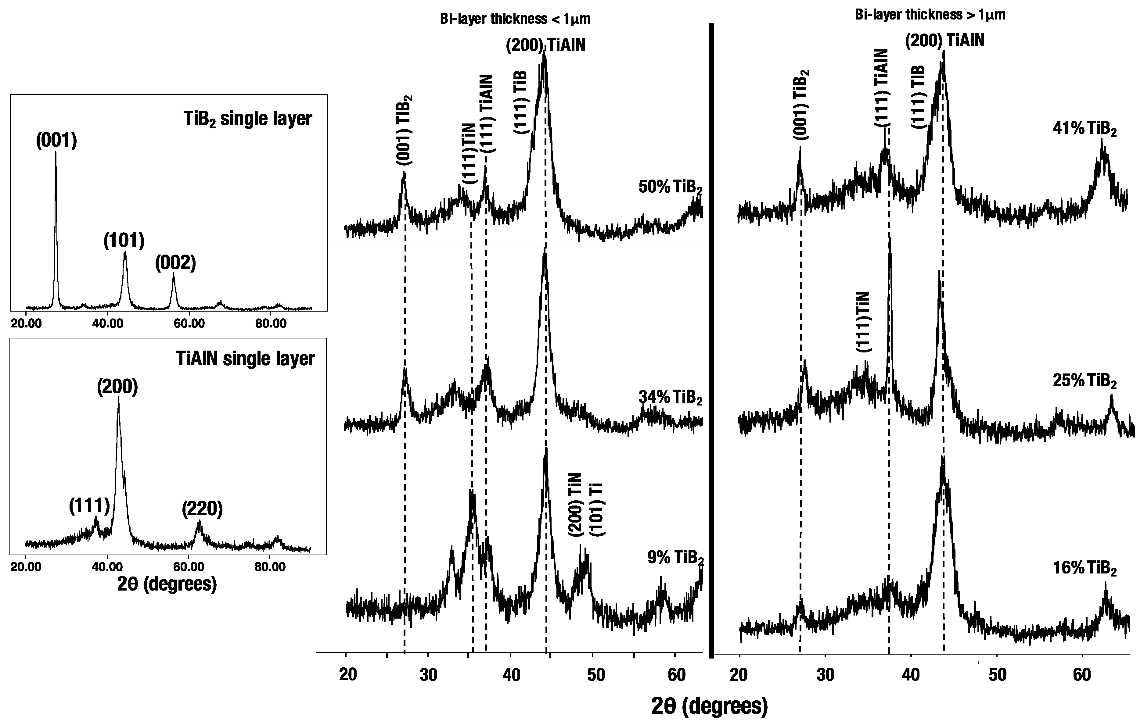
Two bilayer thickness designs have been investigated—set A with a bilayer thickness less than 1 μm, and set B with a bilayer thickness greater than 1 μm. The film thickness was calibrated by depositing a monolayer coating onto a glass slide for a set period of time and then using a Veeco DekTak (Veeco, St. Ives, UK) to obtain the film thickness. The TiB2 content, the measured LC using the scratch tester operating with increasing loads over 1–100 N, along with the associated friction coefficient are reported in Table 1.

3.1. XRD Analysis

The X-ray diffraction patterns from a TiB2 and TiAlN monolayer are presented in Figure 1 together with the XRD θ–2θ diffractograms obtained from the TiAlN/TiB2 multilayers. A TiB2 monolayer crystallises preferentially with a basel plane (001) orientation at an approximate 2θ of 27°, with secondary peaks at 44° (101), 56° and 64° (002), corresponding to highly crystalline TiB2 [14]. A monolayer of TiAlN grows preferentially on the (200) plane and includes secondary peaks on the (111) and (220) planes, corresponding to a cubic NaCl ordered structure as reported by other studies for TiAlN [26]. For the multilayer coatings and for both sets of bilayer thicknesses, the (200) plane of the TiAlN phase dominates. In the case of samples from set A, with a bilayer thickness of <1 μm, the width of the (200) peak of the TiAlN becomes sharper as the TiB2 content is reduced from 50% to 9%, indicating an increase in TiAlN grain size with reducing TiB2 content. Additional secondary peaks appear in the coating with 9% TiB2, corresponding to TiN or either Ti. We propose that these secondary phases form strong bonds with both the TiAlN and TiB2 phases, demonstrated by other research studies to produce the low friction coefficients measured in this sample [27,28]. The TiAlN (111) reflection is also present in the multilayer coating with 9% TiB2. Peaks associated with a boron nitride phase corresponding to the formation of B2O3 were not observed, as these are typically of low intensity compared to the primary TiB2 phases [29].

3.2. Tribological Characteristics

A rapid change in μ at a given load is denoted by • in Figure 2 and is the LC indicating an initial failure in the coating. The measured initial failure at low loads is due to conformal or tensile cracking in the coating which remains adherent to the surface. Further increases in load produce coating failure and de-adhesion from the substrate by spalling, buckling or chipping [30]. The tribological characteristics of a TiAlN monolayer coating deposited at different partial pressures of nitrogen are plotted in Figure 2a. For loads below 50 N, the measured friction coefficients of TiAlN monolayers deposited at a nitrogen partial pressure of 20% and 40% is around 0.4, and above 50 N increase in the case of the monolayer deposited in a 40% nitrogen partial pressure. For the thin film produced in a nitrogen partial pressure of 28%, the friction coefficient decreases from 1.0 to around 0.4 with increasing load, converging with the monolayer film deposited in a 20% nitrogen partial pressure. The characteristics of a TiAlN monolayer coating vary according to parameters such as the nitrogen partial pressure during growth and film stoichiometry [31]. These changes affect the microstructure and surface roughness of TiAlN [32,33] strongly influencing properties such as the hardness and Young’s modulus [33,34]. In Figure 2a, the tribological properties of a TiAlN monolayer are compared and show changes in the friction coefficient with changes in the nitrogen partial pressure during growth, which can be attributed to changes in the shape of the grains [34], with increased incorporation of nitrogen changing the crystal orientation of the α-Ti lattice [35]. Other studies report the formation of a surface tribo-film due to oxidation in air, which modifies coating lubricity [36,37]. Therefore, a combination of these factors may account for the observations reported here.
In the case of TiB2 deposited with a power density of 5.3 W/cm2 Figure 2b, μ decreases from around 0.55 to approximately 0.4 with increasing loads. At a power density of 4.3 W/cm2 the first recognisable rapid change in μ occurs at loads between 5 N and 6 N. However, the coating retains a friction coefficient similar to the coatings deposited at 5.3 W/cm2. This suggests that, even though there are indications that the coating deposited at 4.3 W/cm2 fails at relatively low loads, material debris is entrapped between the indenter and film surface, still serving in the wear mechanics. Figure 2c and Figure 3d show the variation in friction coefficient with load for bilayer thicknesses less than and greater than 1 μm, respectively. In the case of the multilayers with bilayer thicknesses <1 μm, Figure 2c, there is a contrast in behaviour between the coating containing 50% TiB2 where μ varies between 0.6 and 0.8, and the coating containing 9% TiB2 where μ remains around 0.2 over the entire load range. The contrast in low frictional characteristics between these films could be due to greater contact stresses in the coating containing 50% TiB2 than the coating containing 9% TiB2, leading to a combination of material phase changes with increasing loads, material compaction or material entrapment during the scratch, which has been evidenced by other studies [38,39]. The behaviour contrasts those coatings where the bilayer thickness exceeds 1 μm, where Figure 2d shows that the μ for multilayers is around 0.5 at loads above 30 N. Although the coating with 25% TiB2 fails a low load around 10 N, it retains its lubricious characteristics, suggesting material debris remains entrapped between the indenter and film surface.

3.3. Multi-Pass, Bi-Directional Wear Studies

Under forging conditions, loads are applied progressively, i.e., the material is pressed against the dies. However, in order to compare and contrast the characteristics of the different coating designs, it was necessary to apply a relatively low load. Thus, a bi-directional wear test at a constant load of 10 N was performed for the two sets of bilayer thicknesses.
Figure 3 plots the measured friction coefficient over 25 cycles and Figure 4 plots the resultant wear scar volume (measured using an optical laser microscope) as a function of TiB2 content in the multilayer coatings. Both sets of multilayer coatings exhibit an increase in μ with increasing numbers of cycles confirming that the coatings are fatiguing with time/distance. There is greater variability in the films where the bilayer thickness is <1 μm compared to films where the bilayer thickness >1 μm. This is probably due to the greater ability of distributing stress within bilayers greater than 1 μm compared to thinner bilayers, where there is increased stress at the interface [40]. A quantitative study allowing inferences in wear behaviour between samples was undertaken by measuring the wear volume as calculated from the wear track depth, the length and its width using a laser confocal microscope. The wear scar volumes measured after the bi-directional wear tests are plotted in Figure 4 together with the measured average μ as a function of the TiB2 content in the coating. Trends in the wear volume data and μ are highlighted using dashed lines. There are two frictional coefficient regimes labelled (1) and (2) in Figure 4a, with a transition at a TiB2 content between 20% and 30%. The two regimes correspond to a lower and higher rate of material loss as shown in Figure 4b. In regime (1), and where the TiB2 content less than 20%, the material does not break up and the loss from the surface is via film delamination, manifesting as having a low sheer stress at the material interface. In contrast, in regime (2), where the TiB2 content is greater than 20%, we postulate that the material breaks up into finer particles, which together at the high loads produces the greater wear rate.
Cross-sectional SEM image analysis shows evidence of intra-layer delamination and lateral cracking in a coating where the TiB2 content is greater than 30%, Figure 5a. In fact, it is evident from Figure 5b that lateral cracks in the TiB2 extend towards the TiAlN interface and are the source of cohesive failure between the layers, thus accounting for the reduced mechanical sheer stresses observed in the coatings between the two frictional coefficient regimes. A thin film with a TiB2 content below 30%, Figure 5c shows that the coating remains adherent to the substrate. The reduced fracture resistance and residual stress in the coating can be attributed to a low hardness of the TiB2 layer, which was not measured as part of this study, but is more likely influenced by the bilayer thickness and modulation period, as reported by other studies [41].
Optical images of the resulting wear scars are presented in Figure 6, comparing a coating with 35% TiB2 with a coating containing 9% TiB2. The contrast in mechanical behaviour between the two sets of samples is evident and shows the result of intra-layer delamination failure in the coating containing 35% TiB2, Figure 6c,d, exhibiting the break-up of the material into finer particles manifested as material-pileup of coating debris ahead of the wear scar. This is not observed for the sample containing 9% TiB2, Figure 6a,b where the coating remains intact.
The measured wear scar volumes for a H-13 substrate, a monolayer of TiB2 and TiAlN, and a multilayer TiAlN/TiB2 system with 9% TiB2 are plotted using a bar graph, Figure 7. The wear scar volumes measured for the coated samples are lower than the uncoated substrate. Compared to monolayer coatings of TiAlN and TiB2, the wear scar volumes of a multilayer TiAlN/TiB2 system with 9% TiB2 are approximately three times lower than those of the substrate, thereby proving the increased wear resistance offered by these composite coatings.

4. Conclusions

Thin film coatings of TiAlN/TiB2 have been fabricated to combat tool wear in forging dies and other manufacturing tools, where premature wear leads to increased downtimes and reduced productivities. The wear characteristics of TiAlN/TiB2 multilayer coatings, where the bilayer thickness and the TiB2 content are varied, have been investigated using XRD, SEM and scratch tests, allowing inferences to be made regarding the effects of the coating designs on the performance attributes. The following observations are noted:
  • X-ray diffraction showed the coatings to be predominately TiAlN orientated (200), with additional phases of TiN and Ti when the TiB2 content is 9%.
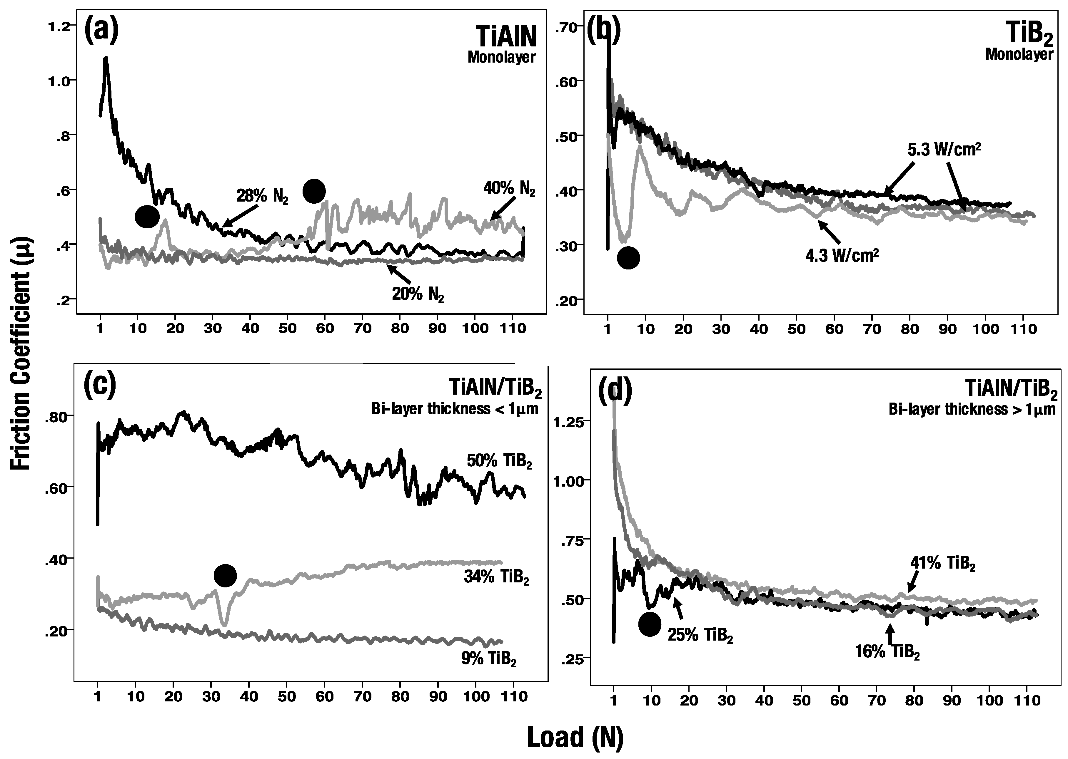
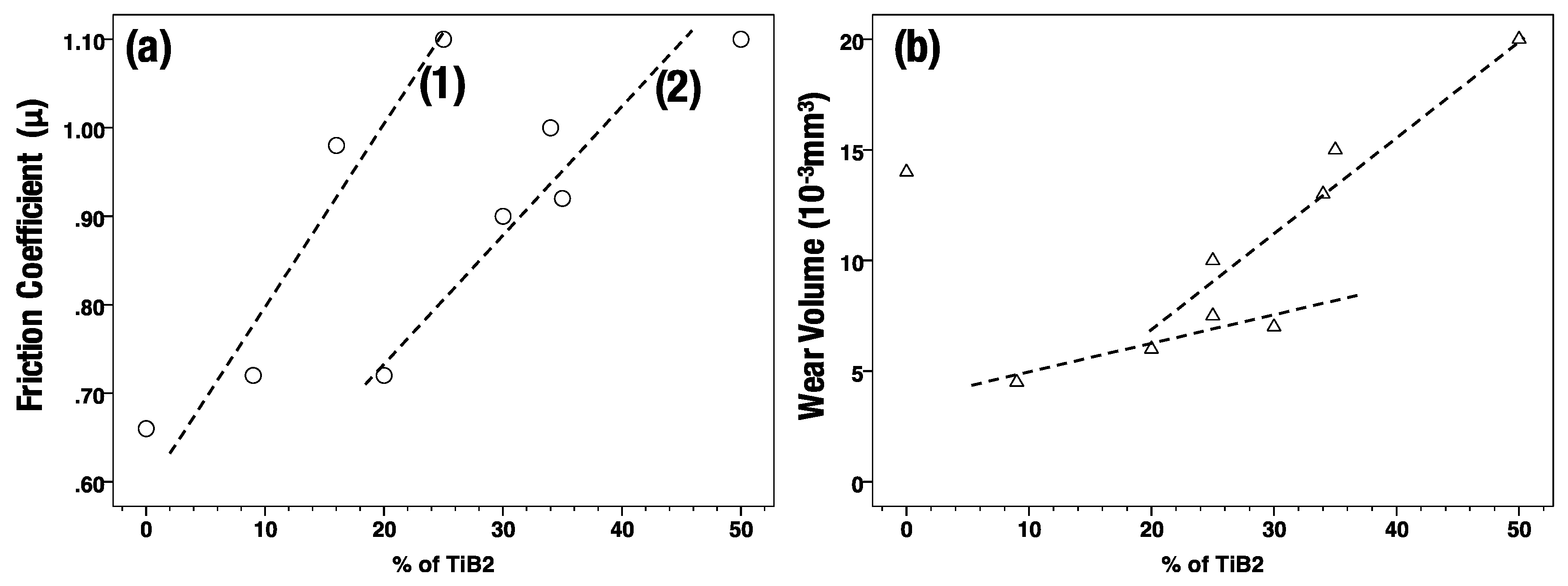
  • Progressive-load scratch tests revealed a contrast in measured friction coefficients between multilayer coatings with bilayer thicknesses less-than and greater-than 1 μm. A coating containing 50% TiB2 and bilayer thicknesses <1 μm, the friction coefficients vary between 0.6 and 0.8 in contrast to around 0.2 for a coating containing 9% TiB2. For bilayer thicknesses >1 μm, the friction coefficients are around 0.5 over the entire load range of 110 N for all the TiB2 compositions measured.
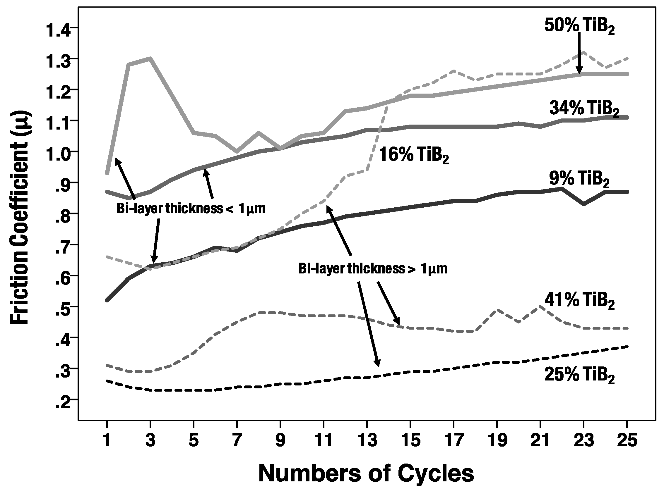
  • Bi-directional wear tests conducted at a constant load of 10 N show that the measured frictional coefficients are approximately 50% lower in coatings with a bilayer thickness >1 μm. This is due to the greater ability to distribute the stress within the layers.
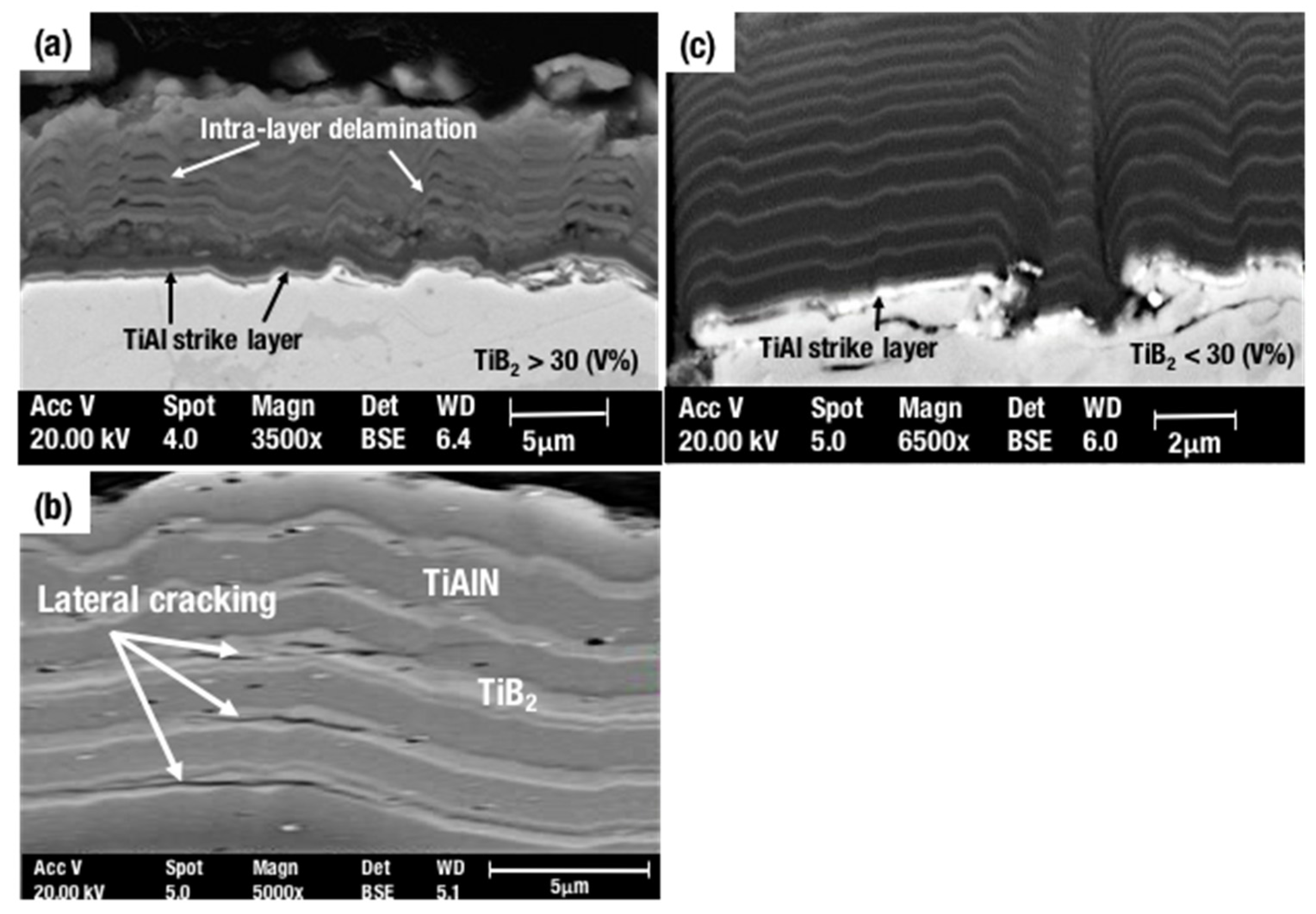
  • There are two observed frictional coefficient regimes corresponding to a lower and high rate of material loss. At the lower regime, with TiB2 contents below 20%, material loss occurs mainly via delamination between the layers, whilst at compositions above this, material loss occurs via a break-up of material into finer particles that in combination with the load results in greater material loss.
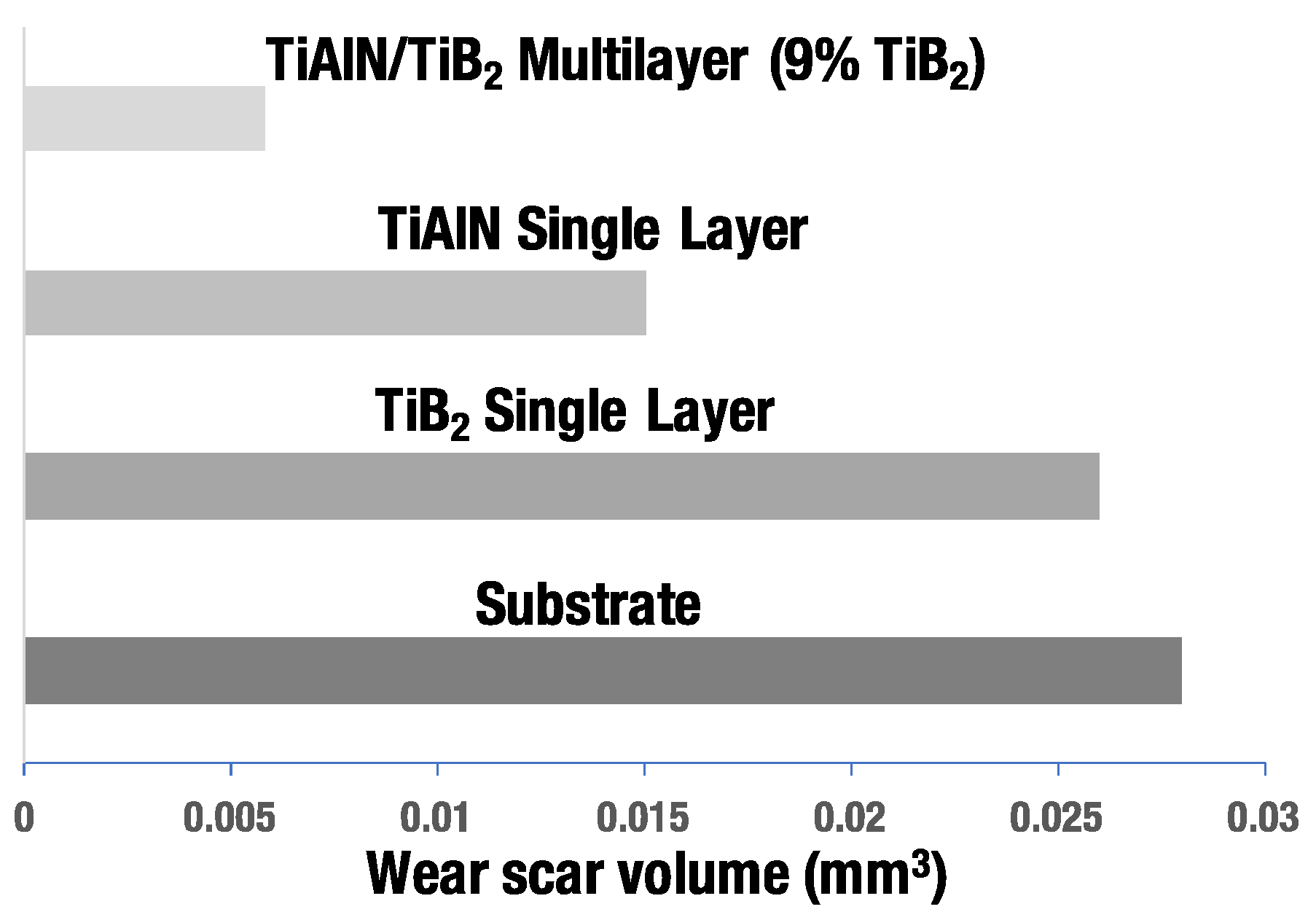
  • The measured wear scar volumes for a TiAlN/TiB2 multilayer coating containing 9% TiB2 is approximately three times lower than that measured on the substrate and half that of a monolayer TiAlN coating, thereby validating the increased wear resistance offered by this coating.

Acknowledgements

Amit Sharma acknowledges the financial assistance to study at Cranfield University provided by Hindustan Aeronautics Limited.

Author Contributions

Jeff Rao and Tim Rose conceived and designed the experiments; Amit Sharma performed the experiments; Jeff Rao, Tim Rose and Amit Sharma analysed the data; Jeff Rao and Tim Rose wrote the paper.

Conflicts of Interest

The authors declare no conflicts of interest.

References

  1. Rao, J.; Rose, T.; Craig, M.; Nicholls, J.R. Wear Coatings for High Load Applications. Procedia CIRP 2014, 22, 277–280. [Google Scholar] [CrossRef]
  2. Nunes, V.; Silva, F.J.G.; Andrade, M.F.; Alexandre, R.; Baptista, A.P.M. Baptista, Increasing the lifespan of high-pressure die cast molds subjected to severe wear. Surf. Coat. Technol. 2017, 332, 319–331. [Google Scholar] [CrossRef]
  3. Prabakaran, V.; Sivakumaran, I.; Palimar, S.P. Experimental investigation of wear characteristics on TiCN-coated AISI 410 steel. Appl. Phys. A 2016, 122, 468. [Google Scholar] [CrossRef]
  4. Ikeda, T.; Satoh, H. Phase formation and characterization of hard coatings in the Ti-Al-N system prepared by the cathodic arc ion plating method. Thin Solid Films 1991, 195, 99–110. [Google Scholar] [CrossRef]
  5. Dobrzański, L.A.; Skrzypek, S.; Pakuła, D.; Mikuła, J.; Křiž, A. Influence of the PVD and CVD technologies on the residual macro-stresses and functional properties of the coated tool ceramics Manufacturing and processing Manufacturing and processing. J. Achiev. Mater. Manuf. Eng. 2009, 35, 162–168. [Google Scholar]
  6. Polvorosa, R.; Suarez, A.; de Lacalle, L.L.; Cerrillo, I.; Wretland, A.; Veiga, F. Tool wear on nickel alloys with different coolant pressures: Comparison of Alloy 718 and Waspaloy. J. Manuf. Process. 2017, 26, 44–56. [Google Scholar] [CrossRef]
  7. Haubner, R.; Lessiak, M.; Pitonak, R.; Köpf, A.; Weissenbacher, R. Evolution of conventional hard coatings for its use on cutting tools. Int. J. Refract. Met. Hard Mater. 2017, 62, 210–218. [Google Scholar] [CrossRef]
  8. Rao, J.; Cruz, R.; Lawson, K.J.; Nicholls, J.R. Sputtered DLC-TiB2 multilayer films for tribological applications. Diam. Relat. Mater. 2005, 14, 1805–1809. [Google Scholar] [CrossRef]
  9. Baran, Ö.; Bidev, F.; Çiçek, H.; Kara, L.; Efeoğlu, İ.; Küçükömeroğlu, T. Investigation of the friction and wear properties of Ti/TiB2/MoS2 graded-composite coatings deposited by CFUBMS under air and vacuum conditions. Surf. Coat. Technol. 2014, 260, 310–315. [Google Scholar] [CrossRef]
  10. Gyawali, G.; Tripathi, K.; Joshi, B.; Lee, S.W. Mechanical and tribological properties of Ni-W-TiB2 composite coatings. J. Alloys Compd. 2017, 721, 757–763. [Google Scholar] [CrossRef]
  11. Smolik, J.; Gulde, M.; Walkowicz, J.; Suchanek, J. Influence of the structure of the composite: “Nitrided layer/PVD coating” on the durability of forging dies made of steel DIN-1.2367. Surf. Coat. Technol. 2004, 180–181, 506–511. [Google Scholar] [CrossRef]
  12. Hovsepian, P.E.; Lewis, D.B.; Luo, Q.; Münz, W.D.; Mayrhofer, P.H.; Mitterer, C.; Zhou, Z.; Rainforth, W.M. TiAlN based nanoscale multilayer coatings designed to adapt their tribological properties at elevated temperatures. Thin Solid Films 2005, 485, 160–168. [Google Scholar] [CrossRef]
  13. Fernández-Valdivielso, A.; López de Lacalle, L.N.; Urbikain, G.; Rodriguez, A. Detecting the key geometrical features and grades of carbide inserts for the turning of nickel-based alloys concerning surface integrity. Proc. Inst. Mech. Eng. Part C 2015, 230, 3725–3742. [Google Scholar] [CrossRef]
  14. Wong, M.S.; Lee, Y.C. Deposition and characterization of Ti–B–N monolithic and multilayer coatings. Surf. Coat. Technol. 1999, 120–121, 194–199. [Google Scholar] [CrossRef]
  15. PalDey, S.; Deevi, S. Single layer and multilayer wear resistant coatings of (Ti,Al)N: A review. Mater. Sci. Eng. A 2003, 342, 58–79. [Google Scholar] [CrossRef]
  16. Aramesh, M.; Attia, H.M.; Kishawy, H.A.; Balazinski, M. Observation of a unique wear morphology of cBN inserts during machining of titanium metal matrix composites (Ti-MMCs); leading to new insights into their machinability. Int. J. Adv. Manuf. Technol. 2017, 92, 519–530. [Google Scholar] [CrossRef]
  17. Munro, R.G. Material properties of titanium diboride. J. Res. Natl. Inst. Stand. Technol. 2000, 105, 709–720. [Google Scholar] [CrossRef] [PubMed]
  18. Sun, Y.D.; Yan, J.Y.; Zhang, S.; Xue, F.Y.; Liu, G.Q.; Li, D.J. Influence of modulation periods and modulation ratios on the structure and mechanical properties of nanoscale TiAlN/TiB2 multilayers prepared by IBAD. Vacuum 2012, 86, 949–952. [Google Scholar] [CrossRef]
  19. Yan, J.Y.; Sun, Y.D.; Li, D.J.; Liu, M.Y.; Dong, L.; Cao, M.; Gao, C.K.; Wang, N.; Deng, X.Y.; Gu, H.Q.; et al. High-temperature stability of TiAlN/TiB2 multilayers grown on Al2O3 substrates using IBAD. Surf. Coat. Technol. 2013, 229, 105–108. [Google Scholar] [CrossRef]
  20. Holleck, H.; Lahres, M.; Woll, P. Multilayer coatings—Influence of fabrication parameters on constitution and properties. Surf. Coat. Technol. 1990, 41, 179–190. [Google Scholar] [CrossRef]
  21. Holleck, H.; Schier, V. Multilayer PVD coatings for wear protection. Surf. Coat. Technol. 1995, 76–77, 328–336. [Google Scholar] [CrossRef]
  22. Barshilia, H.C.; Prakash, M.S.; Jain, A.; Rajam, K.S. Structure, hardness and thermal stability of TiAlN and nanolayered TiAlN/CrN multilayer films. Vacuum 2005, 77, 169–179. [Google Scholar] [CrossRef]
  23. Cruz, R.; Rao, J.; Rose, T.; Lawson, K.; Nicholls, J.R. DLC-ceramic multilayers for automotive applications. Diam. Relat. Mater. 2006, 15, 2055–2060. [Google Scholar] [CrossRef]
  24. Rodríguez, C. Cutting Edge Preparation of Precision Cutting Tools by Applying Micro-Abrasive Jet Machining and Brushing; Kassel University Press GmbH: Kassel, Germany, 2009. [Google Scholar]
  25. Babu, S. A Material Based Approach to Creating Wear Resistant Surfaces for Hot Forging. Ph.D. Thesis, The Ohio State University, Columbus, OH, USA, 2004. [Google Scholar]
  26. Kim, C.K.; Shim, W.J. Analysis of contact force and thermal behaviour of lip seals. Tribol. Int. 1997, 30, 113–119. [Google Scholar]
  27. Fei, C.H.E.N.; Wang, T.M.; Chen, Z.N.; Feng, M.A.O.; Qiang, H.A.N.; Cao, Z.Q. Microstructure, mechanical properties and wear behaviour of Zn-Al-Cu-TiB2 in situ composites. Trans. Nonferr. Met. Soc. China 2015, 25, 103–111. [Google Scholar] [CrossRef]
  28. Kumar, S.; Chakraborty, M.; Sarma, V.S.; Murty, B.S. Tensile and wear behaviour of in situ Al–7Si/TiB2 particulate composites. Wear 2008, 265, 134–142. [Google Scholar] [CrossRef]
  29. Chen, J.S.; Wang, J.L. Diffusion Barrier Properties of Sputtered TiB2 between Cu and Si. J. Electrochem. Soc. 2000, 147, 1940–1944. [Google Scholar] [CrossRef]
  30. Shenoy, V.B.; Schwartzman, A.F.; Freund, L.B. Crack patterns in brittle thin films. Int. J. Fract. 2001, 109, 29–45. [Google Scholar] [CrossRef]
  31. Kimura, A.; Hasegawa, H.; Yamada, K.; Suzuki, T. Effects of Al content on hardness, lattice parameter and microstructure of Ti1–xAlxN films. Surf. Coat. Technol. 1999, 120–121, 438–441. [Google Scholar] [CrossRef]
  32. Cheng, Y.; Tay, B.; Lau, S.; Shi, X.; Chua, H. Deposition of (Ti, Al)N films by filtered cathodic vacuum arc. Thin Solid Films 2000, 379, 76–82. [Google Scholar] [CrossRef]
  33. Bujak, J.; Walkowicz, J.; Kusiński, J. Influence of the nitrogen pressure on the structure and properties of (Ti,Al)N coatings deposited by cathodic vacuum arc PVD process. Surf. Coat. Technol. 2004, 180, 150–157. [Google Scholar] [CrossRef]
  34. Obrosov, A.; Gulyaev, R.; Ratzke, M.; Volinsky, A.A.; Bolz, S.; Naveed, M.; Weiß, S. XPS and AFM Investigations of Ti-Al-N Coatings Fabricated Using DC Magnetron Sputtering at Various Nitrogen Flow Rates and Deposition Temperatures. Metals 2017, 7, 52. [Google Scholar] [CrossRef]
  35. Oliveira, J.C.; Manaia, A.; Cavaleiro, A. Hard amorphous Ti-Al-N coatings deposited by sputtering. Thin Solid Films 2008, 516, 5032–5038. [Google Scholar] [CrossRef]
  36. Wang, X.; Kwon, P.Y.; Schrock, D. Friction coefficient and sliding wear of AlTiN coating under various lubrication conditions. Wear 2013, 304, 67–76. [Google Scholar] [CrossRef]
  37. Mo, J.L.; Zhu, M.H. Tribological oxidation behaviour of PVD hard coatings. Tribol. Int. 2009, 42, 1758–1764. [Google Scholar] [CrossRef]
  38. Ramadoss, R.; Kumar, N.; Pandian, R.; Dash, S.; Ravindran, T.R.; Arivuoli, D.; Tyagi, A.K. Tribological properties and deformation mechanism of TiAlN coating sliding with various counterbodies. Tribol. Int. 2013, 66, 143–149. [Google Scholar] [CrossRef]
  39. Tillmann, W.; Vogli, E.; Momeni, S. Mechanical and tribological properties of Ti/TiAlN duplex coatings on high and low alloy tool steels. Vacuum 2009, 84, 387–392. [Google Scholar] [CrossRef]
  40. Yao, S.H.; Su, Y.L.; Kao, W.H.; Liu, T.H. Tribology and oxidation behavior of TiN/AlN nano-multilayer films. Tribol. Int. 2006, 39, 332–341. [Google Scholar] [CrossRef]
  41. Sun, Y.D.; Li, D.J.; Gao, C.K.; Wang, N.; Yan, J.Y.; Dong, L.; Cao, M.; Deng, X.Y.; Gu, H.Q.; Wan, R.X. The effect of annealing on hardness, residual stress, and fracture resistance determined by modulation ratios of TiB2/TiAlN multilayers. Surf. Coat. Technol. 2013, 228, S385–S388. [Google Scholar] [CrossRef]
Figure 1. XRD θ–2θ diffractograms of TiAlN-TiB2 multilayer coatings with different TiB2 contents.
Coatings 08 00012 g001
Figure 2. Tribological investigations of (a) monolayer TiAlN deposited in different partial pressures of nitrogen, and (b) monolayer TiB2 deposited with different power densities. Graphs (c,d) show the contrast in characteristics between the two sets of bilayer thicknesses, with coatings fabricated with a bilayer thickness of >1 μm showing frictional coefficients of around 0.5 with little or no variability between the compositions in contrast to those where the bilayer thickness is of <1 μm.
Coatings 08 00012 g002
Figure 3. Bi-directional wear test performed at a constant load of 10 N for the two sets of coatings. The solid lines are for the multilayer coatings with a bilayer thickness >1 μm and the dashed lines are for the multilayers where the bilayer thickness is <1 μm.
Coatings 08 00012 g003
Figure 4. The measured CoF (a) and wear scar volumes (b) of TiAlN/TiB2 multilayer coatings. There are two observed frictional coefficient regimes corresponding to a lower and higher rate of material loss, labelled (1) and (2). In regime (1), material loss occurs mainly via delamination between the layers; regime (2), material loss occurs via a break-up of material into finer particles that in combination with the loads results in greater material loss.
Coatings 08 00012 g004
Figure 5. SEM images of cross-sectional TiAlN/TiB2 multilayer coatings. The light-coloured bands in the images are from TiB2. Image (a) is from a coating where the TiB2 content is greater than 30%, producing intra-layer delamination at the TiAlNi/TiB2; (b) Cross-section of the coating showing the lateral cracks formed in the TiB2 layers; Image (c) shows a coating with no intra-layer delamination when TiB2 is below 30%.
Coatings 08 00012 g005
Figure 6. SEM images of a wear scar on a sample with 9% and 35% TiB2 (images (a,b) showing the finish and middle sections of the scratch) and a sample with 35% TiB2 (images (c,d) showing the finish and middle sections of the scratch). The arrow shows the direction of the scratch.
Coatings 08 00012 g006
Figure 7. A comparison of wear-scar volumes obtained from multi-pass, bi-directional wear trials conducted at a constant load of 10 N.
Coatings 08 00012 g007
Table 1. Multilayer coatings of TiAlN/TiB2 deposited in this study. Coatings from set A have a bilayer thickness <1 μm and coatings from set B have a bilayer >1 μm. The critical loads (LC) and the friction coefficients (μ) are measured from the scratch tests.
Bilayer Thickness PeriodSample IDCoating Thickness (μm)Bilayer Thickness λ (μm)Volume Fraction TiB2 (%)Critical Load (N)
LC ± 0.25%
Friction Coefficient (μ)
λ < 1 μmA160.350250.60
A25.50.3530480.40
A380.434400.35
A45.50.535450.40
A56.50.79700.20
λ > 1 μmB1101.341400.5
B26.31.120630.45
B3182.72580.45
B472.416800.4

