Abstract
In this paper, interfacial stress analysis for a brittle coating/ductile substrate system, which is involved in a sliding contact with a rigid ball, is presented. By combining interface mechanics theory and the image point method, stress and displacement responses within a coated material for normal load, tangential load, and thermal load are obtained; further, the Green’s functions are established. The effects of coating thickness, friction coefficient, and a coating’s thermoelastic properties on the interfacial shear stress, τxz, and transverse stress, σxx, distributions are discussed in detail. A phenomenon, where interfacial shear stress tends to be relieved by frictional heating, is found in the case of a coating material’s thermal expansion coefficient being less than a substrate material’s thermal expansion coefficient. Additionally, numerical results show that distribution of interfacial stress can be altered and, therefore, interfacial damage can be modified by adjusting a coating’s structural parameters and thermoelastic properties.
1. Introduction
Today, the key elements, such as bearings and gears, are under great pressure to meet the legislative demands of long life and high operational speeds [1,2,3]. These challenges can be achieved by employing high hardness, anti-corrosion, and wear-resistant brittle coatings, such as metal nitride coatings, metal oxide coatings, diamond-like carbon (DLC), etc., to protect working surfaces, as well as adopting high strength steel [4,5]. However, the huge mismatch between coatings and steel substrates in thermoelastic properties always leads to interfacial stress concentrations, which are induced thermally and mechanically, thus, increasing the risk of coating delamination. To avoid blindness in design and application, an interfacial stress analysis of coated solids in dry sliding contacts is essential.
Thus far, many researchers have established Hertzian contact models for coated, elastic semi-infinite space. Linearly, elastic theory uses various forms of transform integration techniques to produce solutions. Gu et al. [6] studied the stress response of coated materials under surface concentrate loading using the image point method. By comparison of calculation results and scratch tests, the notion that the load bearing capacities of DLC-coated Si3N4 was 1.5–3 times larger than that of DLC-coated M50. O’Sullivan and King studied the contact of coated materials using Papkovich–Neuber potentials [7]. Wang and Liu [8,9] applied fast Fourier transformation (FFT) to speed up calculations based on the work of O’Sullivan and King. A combination of FFT and Papkovich–Neuber potentials were further extended to study sliding contacts and partial slip contact problems for solids coated with a monolayer or a gradient layer [10,11]. The finite element method (FEM) was also used in studying interfacial adhesion strengths between coatings and substrates [11,12,13,14,15]. The Hertzian contact problem of coated materials has been extensively studied during past few decades; and a great number of useful conclusions have been drawn. However, the engineering applications of coatings still have a certain degree of blindness due to the small amount of research on the stress responses of coated materials involved in a thermoelastic contact. Ke et al. [16] discussed the effect of the friction coefficient and sliding velocity on the temperature distribution of semi-infinite materials coated with a gradient material. Choi et al. [17] established a two-dimensional thermoelastic contact model for a rigid flat punch sliding over the surface of a graded coating/substrate system. However, little attention has been paid to the interfacial stress distributions of coated solids involved in thermoelastic contacts. As a matter of fact, a significant amount of frictional heat is generated on the surface of coated materials involved in dry sliding contacts. Thermally induced deformation, subsequently, changes the Hertzian stress distribution of coated materials from the surface to several micrometers in depth, especially for hard coatings, which are distinguished from substrates in regard to thermoelastic properties. Thus, to fulfill a thorough optimization of a hard coating–substrate system, it is necessary to establish an interfacial stress analysis model for thermoelastic contacts.
In this paper, a stress analysis model for coated materials under thermoelastic contact conditions is built, based on interface mechanics. The Green’s functions of the stress and displacement fields of coated materials for a normal force, tangential force, and thermal loading are established. With the aim of exploring ways to reduce the risks of delamination of hard coatings from steel substrates, the effects of the friction coefficient, coating thickness, and thermoelastic properties on interfacial shear stress τxz and transverse stress σxx distributions are investigated, as these two stresses are believed to be strongly related to the propagation of interface cracks in hard coating–substrate systems [18,19,20].
2. Theory
2.1. Description of the Thermoelastic Contact Model
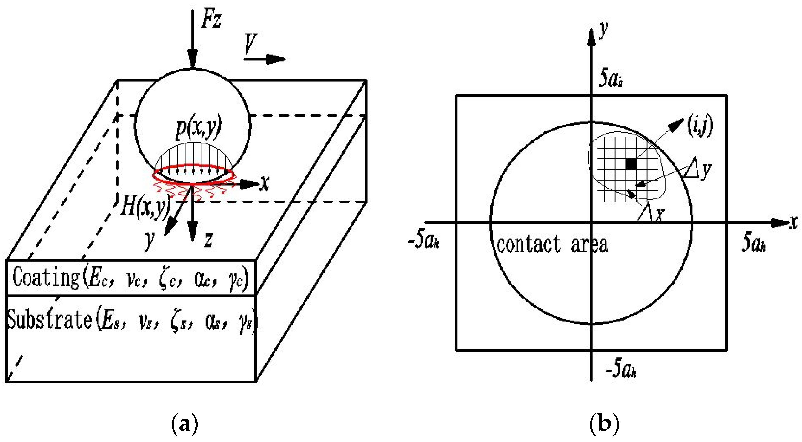
As shown in Figure 1a, a rigid insulated ball is subjected to force Fz and slides on the surface of a coated, isotropic, elastic half space with a constant speed, V, in the positive x-direction.
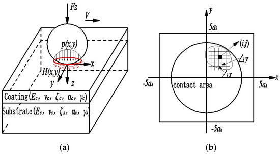
Figure 1.
Schematic of the thermoelastic contact problem. (a) A rigid insulated ball sliding over the surface of a coated solid; (b) Contact area meshing.
The moving coordinate system (x,y,z) is attached to the ball with plane xOy coinciding with the surface of the coated material; that is, the contact area will remain stationary with respect to the movement of the ball. The normal pressure distribution is p(x,y) N·m−2; then, the friction force distribution, q(x,y) N·m−2, and the distribution of frictional heat flux, H(x,y) W·m−2, are generated within the contact region, with f being the friction coefficient. Their relationships are as follows:
q(x,y) = fp(x,y), H(x,y) = fvp(x,y)
Consider this thermoelastic contact problem at room temperature in ambient humidity. Because of the thermal conductive coefficient of the air being always less than 10−3 times of that parameter for the coating material according to Reference [21], the free surface is assumed to be thermally insult. Due to punch sliding with a constant velocity, the temperature will very quickly approach a steady-state value, thus, the convection term in the heat equation is neglected. The coating and substrate are both isotropic materials, with Ec, vc, ζc, αc, and γc being the elastic modulus, Poisson ratio, thermal conductive coefficient, thermal expansion coefficient, and thermal diffusion coefficient for the coating material, respectively, and Es, vs, ζs, αs, and γs being the same parameters for the substrate material.
According to Reference [22], as shown in Figure 1b, in order to obtain contact pressure p(x,y), an area with [–5ah, 5ah] × [–5ah, 5ah] in the x and y directions is uniformly divided into Nx × Ny surface elements, centered on the grid nodes. Here, ah is the Hertz contact radius without coating and thermal effects, and Nx and Ny are the number of elements in the x and y directions. As being proved in Reference [23], the contact pressure distribution can be approximated by a piecewise constant function that is uniform within each surface element with errors being less than 0.01% in the case of Nx and Ny being equal to 32. A more finely meshed surface network, with Nx × Ny being equal to 128 × 128, is adopted in this paper. With the displacements of the element being represented by its central grid; the contact problem can be expressed as a discretized form:
For arbitrarily surface element (i,j), p(i,j) is the normal pressure, g(i,j) is the gap between the surfaces of two bodies in contact after external contact load and thermal load was applied, g0(i,j) is the initial gap before external mechanical load and heat flux applied on the ball, upz(i,j) is the surface displacement of the coated material, which was induced mechanically, utz(i,j) is the surface displacement of the coated material, which was induced thermally, Δx and Δy are the discretization lengths in the x and y directions, δ is the normal approach, and Ωc is the contact area.
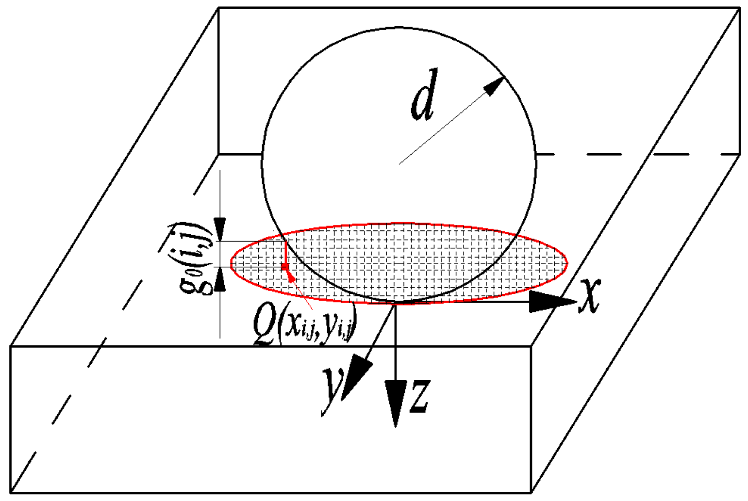
As illustrated in Figure 2, the ball radius is noted as d. The central point of elements (i,j) is noted as Q, with xi,j and yi,j being the positions of point Q in the xOy plane.
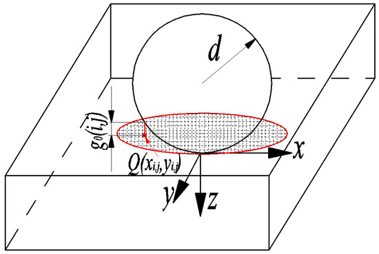
Figure 2.
Schematic description of the initial gap between surface elements and ball.
The initial gap g0(i,j) can be described as the distance between the central point Q and the outer surface of the ball in the z direction:
Due to zi,j << d within the contact zone, the relationship between g0(i,j) and xi,j, yi,j can be described as
Total normal displacement uz(i,j) can be obtained by the accumulation effects of the normal contact pressure and thermal loading of each surface element on the z-displacement of element (i,j).
where Gzp and Gzt are Green’s functions of displacement in the z-direction for a normal load and a thermal load. By applying the complementary energy principle to the thermal contact problem, we have
With the aid of the quadratic programming method, the true contact pressure, p(i,j), can be obtained, at which point contact complementary energy V* is minimal and p(i,j) > 0 is within the contact area.
After gaining contact pressure distribution and heat flux, the stress field can be obtained as follows:
where σAA is an arbitrary stress component of point (x0,y0,z0) within a semi-infinite space (AA may refer to xx, yy, xy, and so on). p(l,k), q(l,k), and H(l,k) are contact pressure distribution, tangential distribution, and heat flux distribution on surface elements (l,k), respectively. GAAp, GAAv, and GAAt are the values of Green’s functions for components AA for a normal load, tangential load, and thermal load at point (x0,y0,z0), respectively.
For an elastic solid with a coating bonded to its surface, the explicit expressions for GAAp, GAAv, and GAAt are not available. However, based on interface mechanics, they can be deduced and expressed in the accumulated form by employing the image point method [24,25]. The detailed deducing is presented in Section 2.2, Section 2.3, and Section 2.4. In this paper, three orders of image points are used to achieve a high accuracy as is proven in Section 3.1.
2.2. Green’s Function for a Point Normal Load Acting on the Surface of a Coated Isotropic Thermoelastic Material
In the analytical model of interface mechanics (Figure 3), a straight interface is formed along the border of the coating and substrate. From Figure 3, we can see that coating I, with thickness h, is used to cover substrateⅡ, and is connected only by the interface. Above the coating, there is a free surface, and a force, marked pz, is applied at point O1 on said surface and is along the z-axis. Considering the symmetries of this problem, a cylindrical coordinate (r,θ,z) is chosen with the r-axis being along the interface, and the z-axis being perpendicular to the r-axis and passing through O1. The two axes intersect at O, namely the global point of origin. Coordinate plane rOθ coincides with the interface.
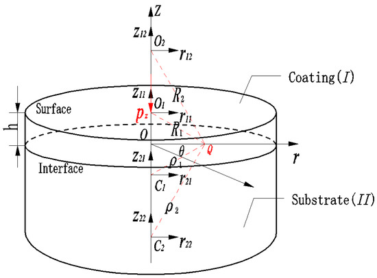
Figure 3.
A point normal force pz acting on the surface of coated material.
The interface stress, shown in Figure 3, can be calculated using the images method from the complex variable function. The boundary conditions and the constraints of the model are equivalent; furthermore, equations were composed using the relationship between stress and strain. As a method of images, the interface and the surface are imagined as mirrors that reflect points O or O1, and will generate infinite points of mirror images. These images influence the interface stresses as a superposition forms, in order to fulfill the boundary conditions and constraints. Namely, the conditions of the interface continuum and free surface are satisfied and interface stresses are gained by superposing the stress solutions of these image points. The image points in the coating space are marked as Ok and those in the substrate space are marked as Ck. Local coordinate systems are established and originate from each image point.
The relationship between the global coordinate and the local coordinates can be written as:
Love’s stress and displacement functions can be written as:
where μ is the shear elasticity modulus, and its relationships with E and v is in the form of μ = 0.5E/(1 + v). u is the displacement component and σ is the stress component in each directions. φ and Ψ are harmonic functions. For coating materials, the harmonic functions are noted as φ1 and Ψ1. For coating materials, the harmonic functions are noted as φ2 and Ψ2. Due to the singular point O1 on the surface of the coating, the harmonic functions for coating material have a relationship with zi and si at the same time. However, because no singular point exists in the substrate material, the harmonic functions for the substrate material only have a relationship with zi. Thus, the harmonic functions can be written as
where i is the sequence number of the image point.
One of the boundary conditions can be established by satisfying the conditions of the interface continuum.
Another boundary condition can be established by satisfying the free surface.
Substituting Equation (10) into Equation (9) using boundary condition Equation (11) and geometry condition z = 0, zi = si = −(2i − 1)h, Ri = ρi on the interface; recursive relations can be obtained:
Substituting Equation (10) into Equation (9) using boundary condition Equation (12) and geometry condition z = h, zi = –(2i − 1)h, si = 2ih, Ri+1 = ρi on the surface, another recursive relation can be obtained:
where κ is the Kappa parameter; κ1 = 3 − 4v1 and κ2 = 3 − 4v2 are Kappa parameters for the coating material and substrate material. α and β are Dundurs parameters [24] for the coating–substrate system.
Thus, φ11(r,z1) and Ω11(r,z1) are the only factors needed to finish the cyclic recursion. Obviously, the Midlin solutions for a point normal load, acting on the surface of a semi-infinite space, satisfy the requirements.
Now, φ and Ψ can be obtained using Equations (13)–(15). Green’s functions can be obtained by substituting Φ and Ψ into Equation (9), and then separating variable pz.
2.3. Green’s Function for a Point Tangential Load Acting on the Surface of a Coated Isotropic Thermoelastic Material
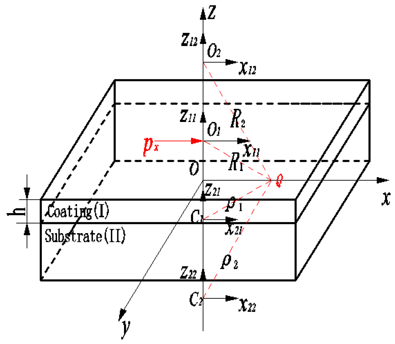
As shown in Figure 4, we can see that coating I, with thickness h, is used to cover substrate II, and is connected only by the interface. Above the coating, there is a free surface, and a tangential force, marked px, is applied at point O1 on said surface and is parallel to the x-axis. A Cartesian coordinate (x,y,z) is chosen with the x-axis and y-axis being along the interface, and the z-axis being perpendicular to the interface and passing through O1. The x-axis and y-axis intersect at O, namely the global point of origin. Coordinate plane xOy coincides with the interface. The image points in the coating space are marked as Ok, and those in the substrate space are marked as Ck. Green’s function for a point tangential load, acting on the surface of a coated isotropic thermoelastic material, can be obtained in the similar way (shown in Section 2.2).
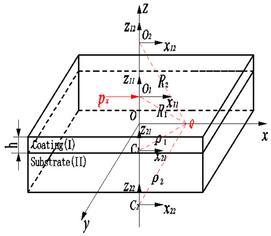
Figure 4.
A point tangential force px acting on the surface of coated material.
Papokovitch’s stress and displacement functions can be written as:
One of the recursive relations can be expressed as:
Another recursive relation can be expressed as:
where μ2/μ1 is noted as Γ and (1 − v1)/(1 − v2) is noted as m.
The Midlin solutions for a point tangential load, acting on the surface of a semi-infinite space, can be written as:
where px is a tangential load. Now, B1, B2, B3 and δ can be obtained by using Equation (17)–(19). Green’s functions can be obtained by substituting B1, B2, B3, and δ into Equation (16) and then separating variable px.
2.4. Green’s Function for a Moving Point Heat Resource Acting on the Surface of a Coated Isotropic Thermoelastic Material
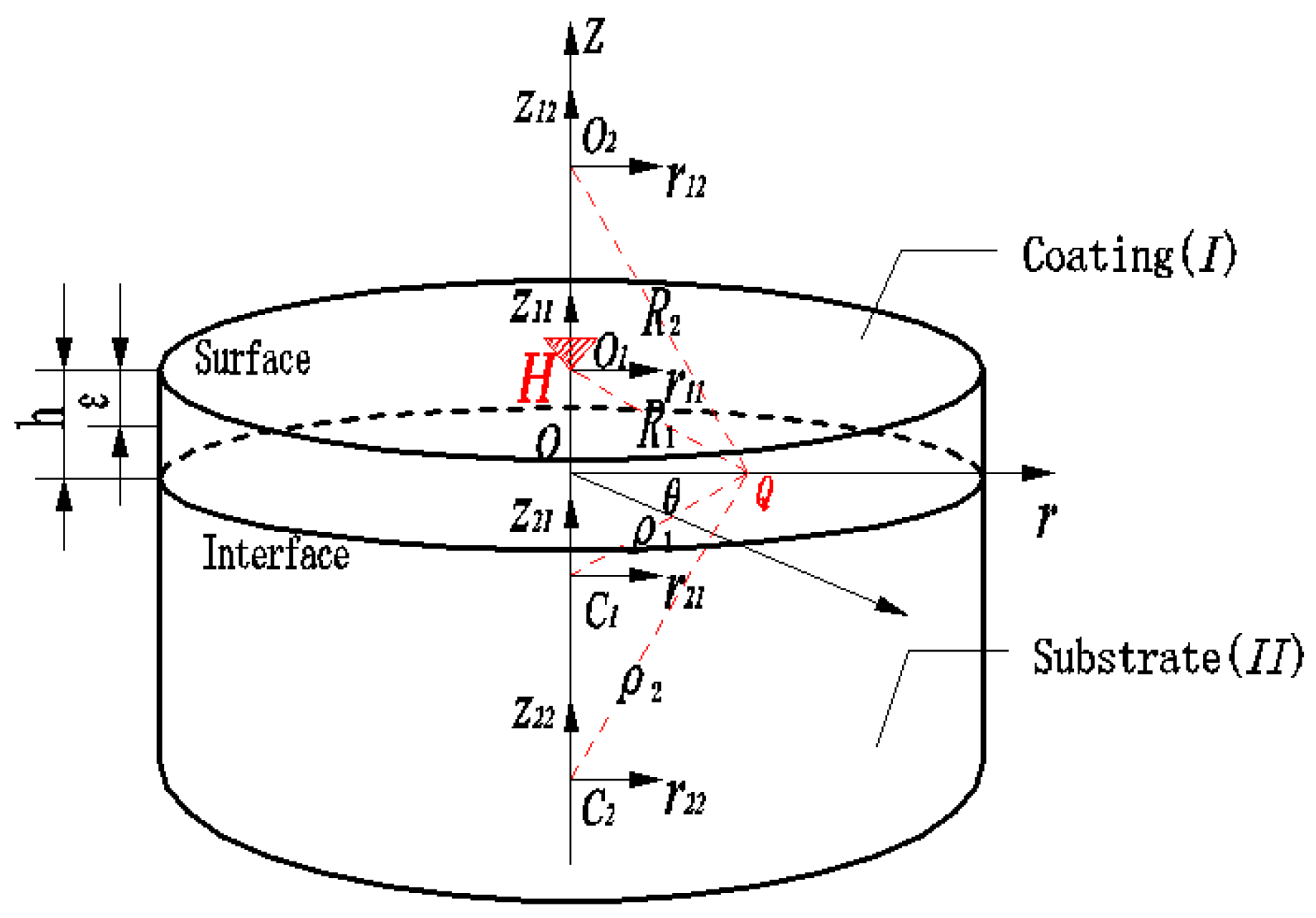
As shown in Figure 5, we can see that coating I, with thickness h, is used to cover substrate II, and is connected only by the interface. Above the coating, there is a free surface, and a moving point heat resource, marked H, is applied at point O1 on said surface. A cylindrical coordinate (r,θ,z) is chosen with the r-axis being along the interface, and the z-axis being perpendicular to the r-axis and passing through O1. The r-axis and z-axis intersect at O, namely, the global point of origin. Coordinate plane rOθ coincides with the interface. The image points in the coating space are marked as Ok and those in the substrate space are marked as Ck. The cyclic recursions and stress and displacement functions for point heat resource are given here.
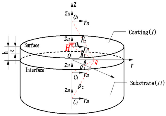
Figure 5.
A moving point heat resource H acting on the surface of coated material.
The general solution for displacement and stress within a semi-infinite space for a thermal load can be written as:
where α is thermal expansion coefficient. λ is the Lame constant [26], its relationships with E and v are in the form of λ = vE/(1 + v)(1 − 2v). Et is the thermal modulus, its relationships with E, v, and α are in the form of Et = 2(λ + 2μ)/α.
Harmonic functions in the coating material can be written as:
Harmonic functions in the substrate material can be written as
One of the boundary conditions can be established by satisfying the continuous conditions of displacement, stress, temperature, and thermal flux on the interface.
Another boundary conditions can be established by satisfying the stress free and thermally insult conditions on the surface.
Additionally, mechanical equilibrium and thermal equilibrium of an infinite plane, ε < z < h, should be satisfied.
where H is the heat flux. As in Grylitsky and Paul [27], we also introduce the Pe number into the above-mentioned equation for the thermoelastic problem. λ2 is the thermal diffusion coefficient for the substrate material.
Substituting Equation (21) into Equation (20), using boundary condition (24) and equilibrium condition (25), one can obtain:
Thus, D11111, D1112, D11112, and D1113 can be obtained from Equation (26). Substituting Equation (21) into Equation (20) using boundary condition (23), one can obtain
Substituting D11111, D1112, D11112, and D1113 into Equation (27), twelve coefficients D211jl and L111jl (j = 1, 2, 3; l = 1, 2) can be obtained. Using boundary conditions Equations (23) and (24), successively, equations such as Equations (26) and (27) can be established and each coefficient of the harmonic functions can be obtained.
Green’s functions for the thermal load can be obtained by substituting ψ1, ψ2, ψ3 and Ψ1, Ψ2, Ψ3 into Equation (20) and separating variable H.
2.5. Solution Procedure
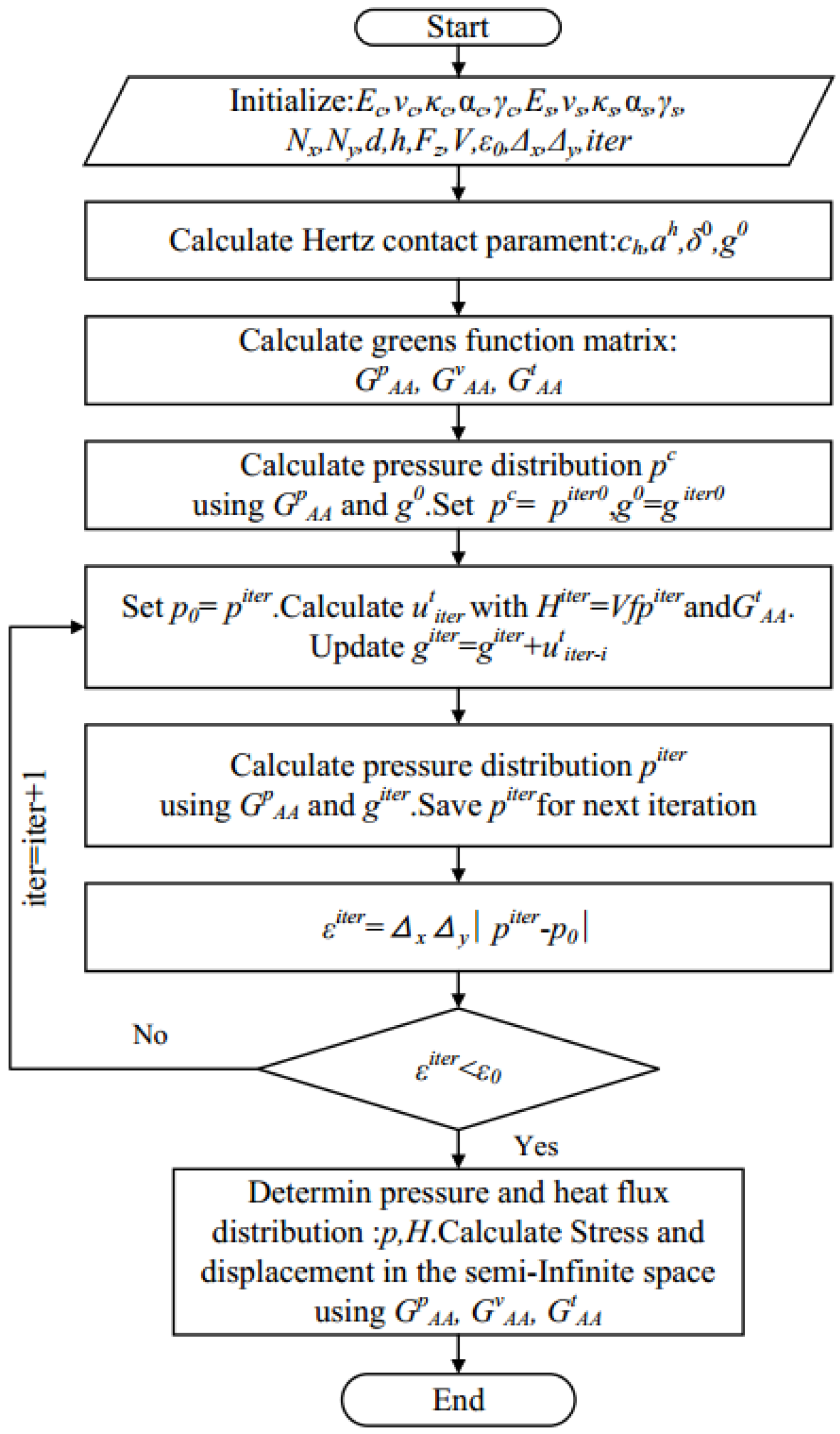
Figure 6 is a flowchart for solving thermoelastic contact problem of coated solids. The solving procedure can be conducted as follows:
- Initialize material parameters and structural parameters. Calculate Hertz contact radius ah, Hertz contact pressure ch, Hertz contact approach δ0, and initial gap g0.
- According to the material parameters and the coating thickness, construct a matrix of Green’s functions for normal load GpAA using Equation (9) and Equations (13)–(15); construct matrix of Green’s function for thermal load GtAA using Equations (20)–(27); construct matrix of Green’s function for tangential load GvAA using Equations (16)–(19).
- Employ GpAA and the quadratic programming method, setting giter0 = g0, calculate Hertzian contact pressure distribution pc using Equations (2)–(6). Set piter0 = pc.
- Obtain surface heat flux Hiter, according to Equation (1) and piter. Employing GtAA and Hiter, calculate thermally induced surface displacement utiter. Update gap giter = giter + utiter.
- Save piter as p0, then update surface contact pressure piter by employing giter, GpAA, and the quadratic programming method.
- Calculate εiter = ΔxΔy| piter − p0| to judge convergence. If εiter < ε0, go to step 7, otherwise go to step 4 for the next iteration.
- Obtain contact pressure p and heat flux H. Calculate σAA using Equation (7) by employing GAAp, GAAv, and GAAt.
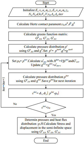
Figure 6.
Flowchart for solving the thermoelastic contact problem of a coated solid.
3. Results and Discussion
The ratio of shear modulus between the coating and substrate is μ = μc/μs, the ratio of thermal expansion coefficient between the coating and substrate is α = αc/αs, and the ratio of the thermal conductive coefficient between the coating and substrate is ζ = ζc/ζs. The following non-dimensional temperature rise, stress components, and coordinates are used:
where Pe2 is the Pecelet Number, λs is the thermal diffusion coefficient for the substrate material, and pn is the non-dimensional contact pressure. tn is the non-dimensional temperature rise. σn-AA is the non-dimensional stress components in an arbitrary direction. ah and ch are the Hertz contact radius and max contact pressure. Coating and substrate material’s Poisson ratios are set to be 0.3. In this study, the substrate material is 52100 steel with Es = 210 GPa, αs = 1.17 × 10⁻⁵ K−1, ζs = 50.2 W·m−1·K−1, and λs = 1.0 × 10⁻⁵ m2·s−1. Max Hertz contact pressure ch is 1.09 GPa and the Hertz contact radius, ah, is 100 μm. Sliding velocity, V, is 2.4 m·s−1; thus, Pe2 is 2.4.
3.1. Model Verification
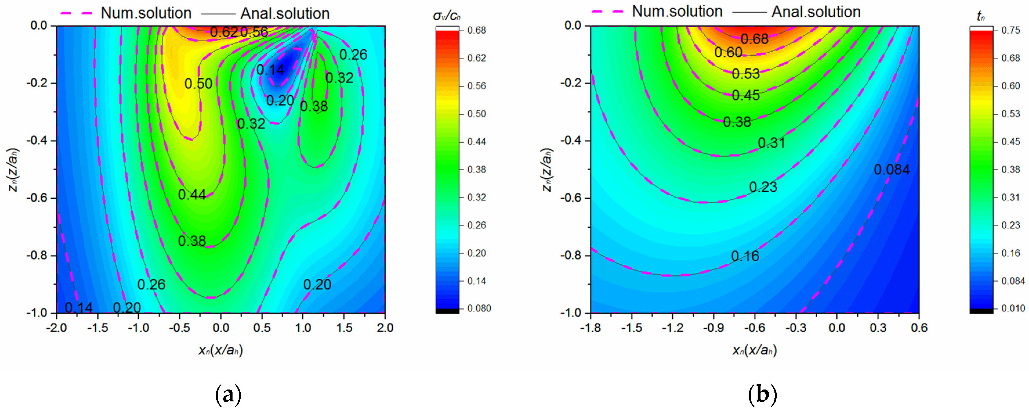
In order to verify the validity of the present model, the numerical results, obtained by setting μ = 1, α = 1, and ζ = 1, are compared with the exact analytical solution given by Johnson and Midlin [21] for the thermoelastic contact problem of solo material semi-space at f = 0.2 and Pe2 = 2.4. The contour plot of the Von Mises stress and temperature on the xz plane are shown in Figure 7a,b, respectively, with numerical results being implied by the dotted line and the analytical results being implied by the solid line. All numerical simulations agree with those from the analytical solutions.
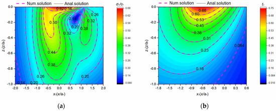
Figure 7.
Comparison between the numerical solution and the analytical solution at μ = 1, α = 1, ζ = 1 and f = 0.2; Pe2 = 2.4. (a) Contour plot of σn−v obtained using the present model and analytical solution. (b) Contour plot of tn obtained by the present model and analytical solution.
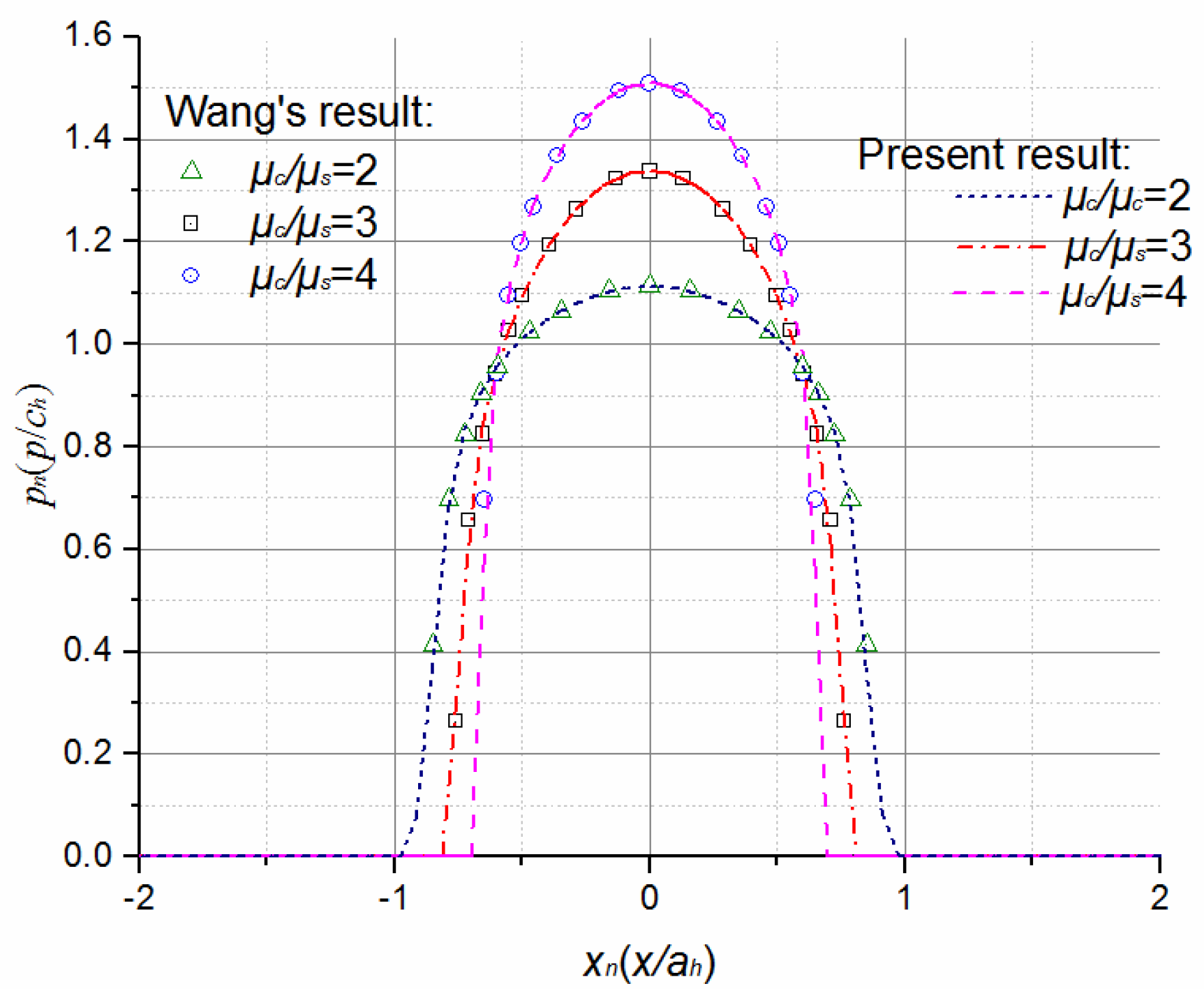
Note that, for verifying the validity of the present model further, the work by Wang [23] for the contact problem of a coated solids without thermal effect can be recovered by assuming V = 0 in the present model. Here, we choose the same material parameters as in Reference [9] and calculate the contact pressure distribution. Figure 8 shows the dimensionless contact stress at h/ah = 0.5, f = 0.2, V = 0 with μc/μs varying from 2 to 4. It is seen that the present results agree very well with Liu’s results.
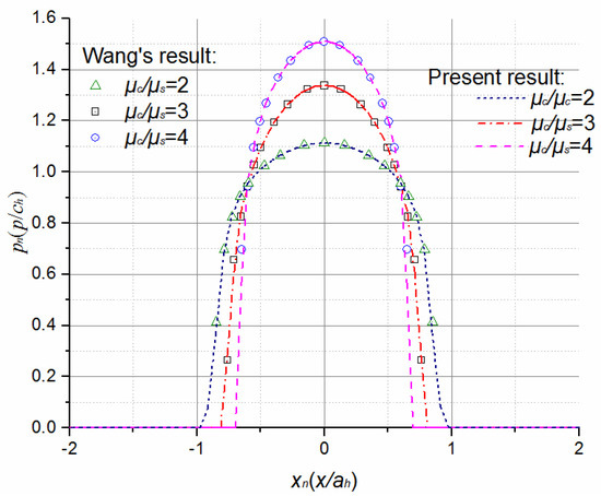
Figure 8.
Comparison of contact pressure obtained from Wang’s result and the present model at h/ah = 0.5, f = 0.2, V = 0 with μc/μs varying from 2 to 4.
3.2. Effects of Friction Coefficient and Coating Thickness on Contact Pressure and Interface Stress Distribution
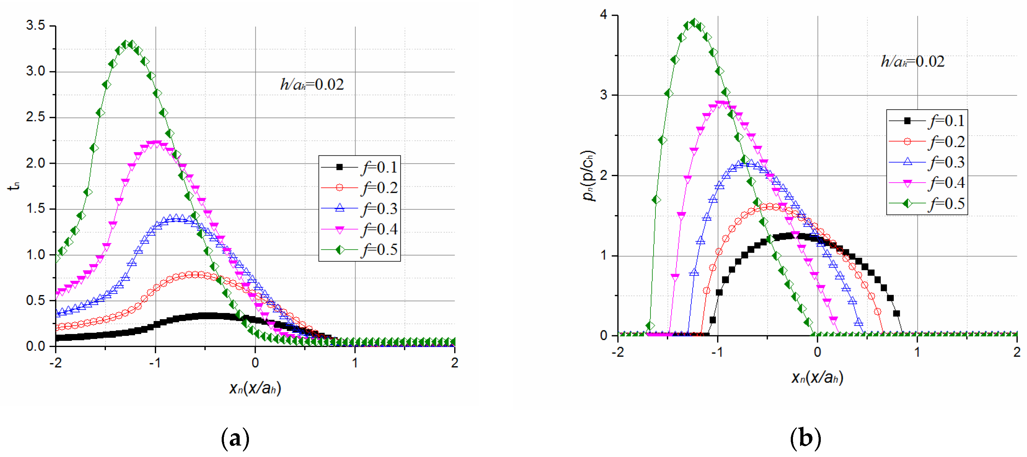
The effects of the friction coefficient on contact pressure and surface temperature are shown in Figure 9. With the increase of f, more frictional heats are generated within the contact zone, and the thermal expansion of the contact surface in the z-direction is enlarged. As shown in Figure 9b, this leads to a decrease in the contact area by 23% and an increase in maximum contact pressure by 307% when f increases from 0.1 to 0.5. A comment to be made regarding Figure 9a is that the magnitude of the surface temperature in proportion to f is offset by greater concentrations in the tail of the contact zone due to the moving of heat resources. Because of the higher thermal expansion in the tail of the contact zone, contact pressure is more concentrated in this area with the increase of f, as shown in Figure 9b.
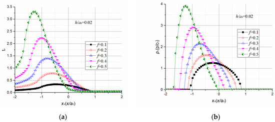
Figure 9.
Effect of f on contact characteristics. (a) Effect of f on contact pressure distribution; (b) Effect of f on surface temperature distribution.
The effect of the friction coefficient on shear stress τn−xz along the intersecting line of plane xoz and the interface is shown in Figure 10, with variations of h/ah at μ = 2, α = 0.3, ζ = 0.5. With the increase of f, the maximum interfacial shear stress increases sharply for coatings with h/ah = 0.02, as shown in Figure 10a, and moderately for coatings with h/ah = 0.25 and h/ah = 0.5, as shown in Figure 10c,d. For coatings with h/ah = 0.1, the maximum interfacial shear stress decreases slightly, and then increases, as shown in Figure 10b. The maximum interfacial shear stress of coated solids with thin coatings (e.g., h/ah = 0.02) is more sensitive to the change of friction coefficient than those that have thick coatings. Traditionally, employing thin coatings is preferable, as lower interfacial shear stress can be obtained as soon as f < 0.3. However, due to being affected by frictional heat, thin coatings (e.g., h/ah = 0.02) are only favored when f is below 0.1.
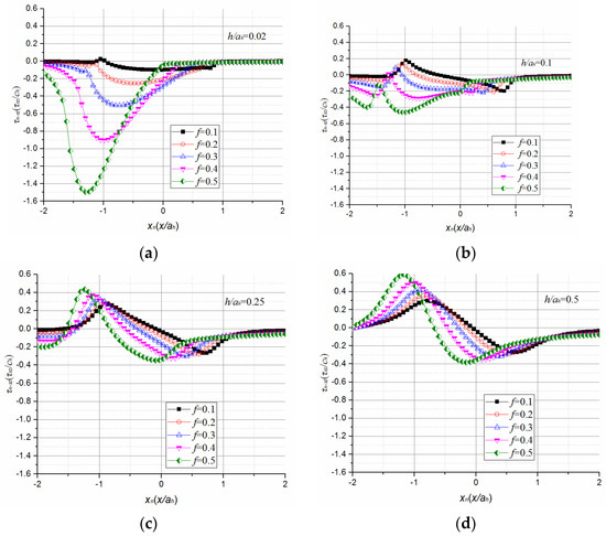
Figure 10.
τn−xz along the intersecting line of plane xoz and interface with various f and h/ah when μ = 2, α = 0.3, ζ = 0.5. (a) With various f at h/ah = 0.02. (b) With various f at h/ah = 0.1. (c) With various f at h/ah = 0.25. (d) With various f at h/ah = 0.5.
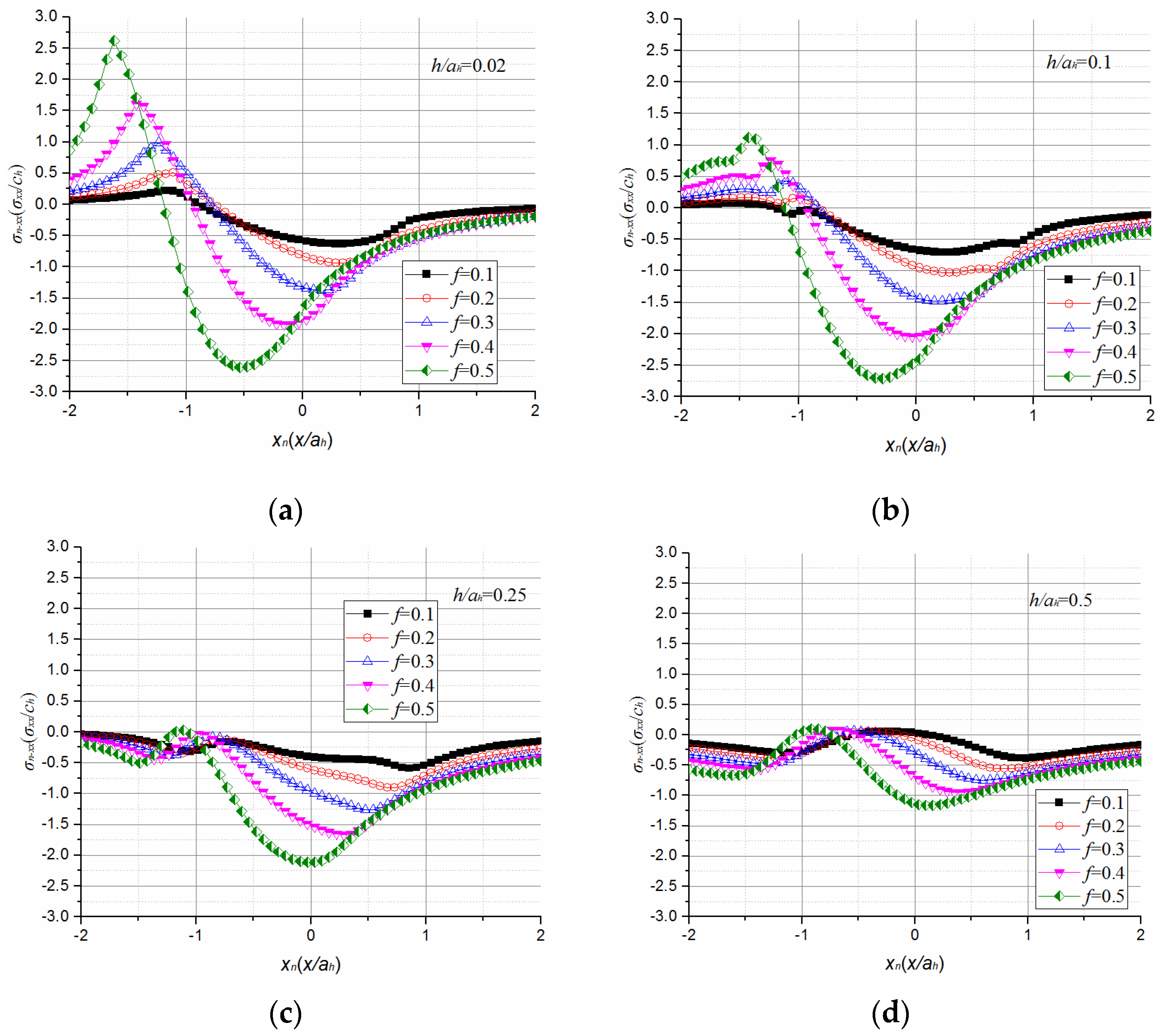
The effect of the friction coefficient on transverse stress σn−xx along the intersecting line of plane xoz and the coating bottom can be inferred from Figure 11, which shows various h/ah at μ = 2, α = 0.3, ζ = 0.5. As shown in Figure 11c,d, coatings with a thickness of h/ah > 0.25 may render interfacial transverse stress σn−xx compressive within the contact zone for various f, counteracting the brittle failure of the coating in general. Meanwhile, thin coatings with a thickness of h/ah = 0.02 may encounter brittle failure at the end of the tail of the contact zone because σn−xx is always tensile in that zone, in all cases of f. For coatings with h/ah = 0.1, brittle failure at the end of the tail of the contact zone may happen in the case where f > 0.2.
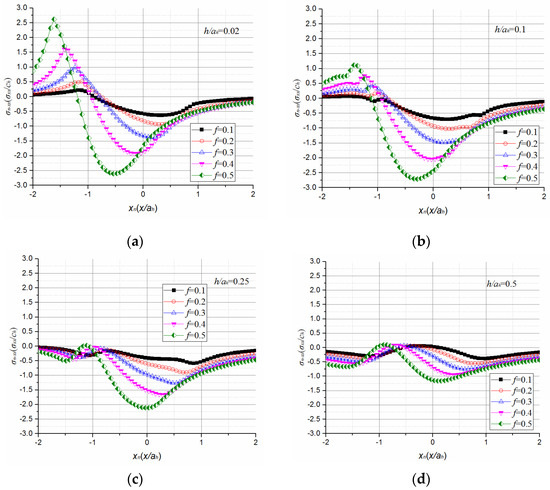
Figure 11.
σn−xx along the intersecting line of plane xoz and interface with various f and h/ah when μ = 2, α = 0.3, ζ = 0.5. (a) with various f at h/ah = 0.02; (b) with various f at h/ah = 0.1; (c) with various f at h/ah = 0.25; (d) with various f at h/ah = 0.5.
By compromising between interfacial shear stress and tensile transverse stress, coatings with thicknesses of about h/ah = 0.02 are preferred in cases where f < 0.1; coatings with a thickness of about h/ah = 0.1 are preferred in the case of 0.1 < f < 0.3, and coatings with a thickness of about h/ah = 0.25 are proposed in cases where f > 0.3.
3.3. Effect of a Coating’s Elastic Modulus and Thermal Expansion Coefficient on Interface Stress Distribution
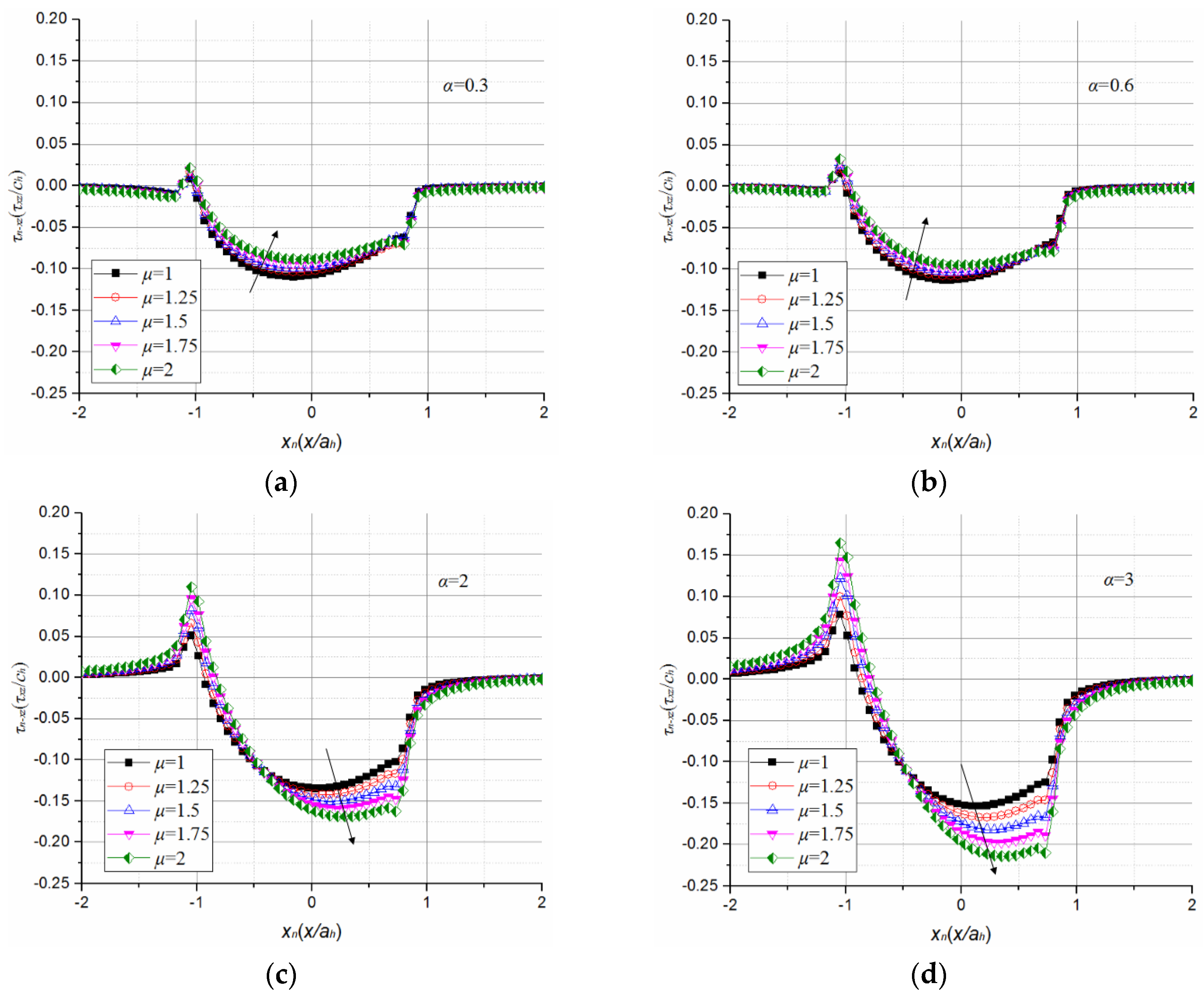
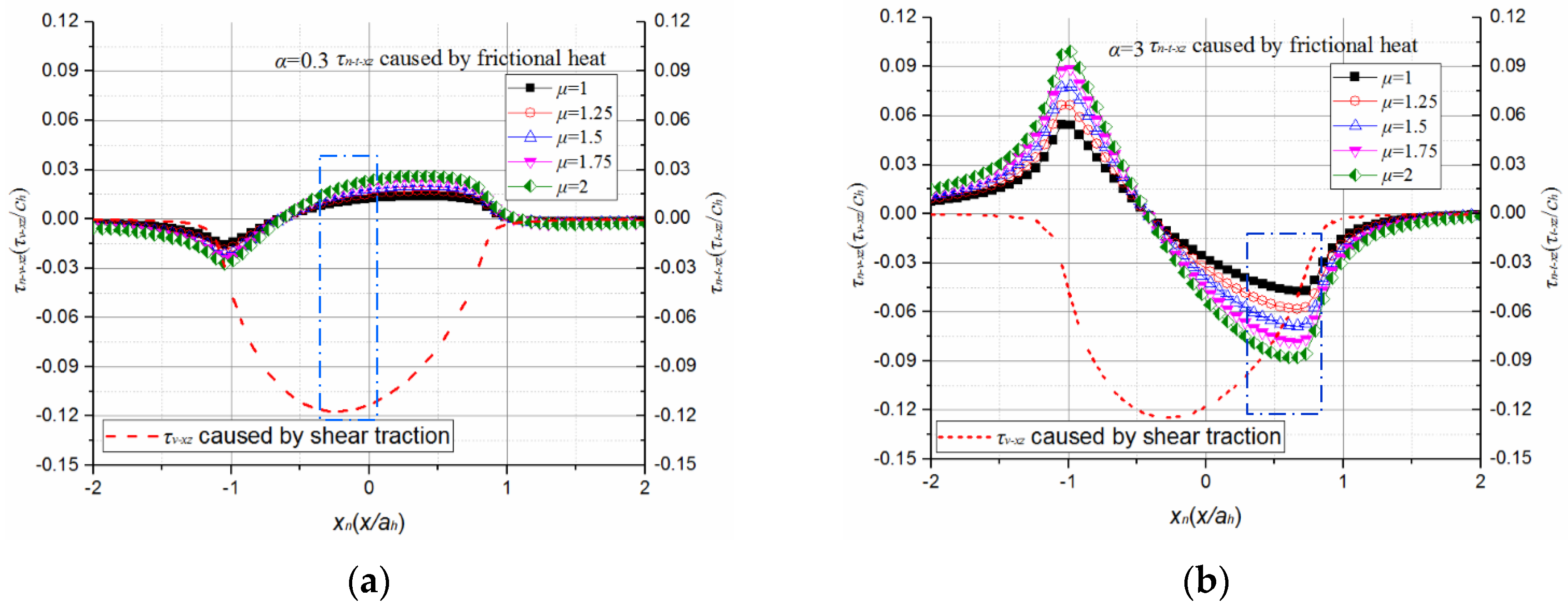
The effects of a coatings’ elastic modulus ratio, μ, on shear stress τn−xz along the intersecting line of plane xoz and the interface are shown in Figure 12, with variations of α at h/ah = 0.02, ζ = 0.5, f = 0.1. As can be inferred from Figure 12c,d, the increase in stiffness of the coating results in a higher interfacial shear stress when α is greater than 1. However, when α is less than 1, the interfacial shear stress decreases dramatically with the increase in the stiffness of the coatings, as can be inferred from Figure 12a,b. With the increase of μ, thermally induced interfacial shear stress τt−xz always increases, as shown in Figure 13. However, the direction of the thermally induced interfacial shear stress component is opposite to that caused by tangential traction when α < 1, as is shown in Figure 13a. Thus, the increase in the thermally induced interfacial shear stress results in the decrease of total interfacial shear stress. While α > 1, the direction of thermally induced interfacial shear stress is the same as that caused by tangential traction, as shown in Figure 13b. Thus, the increase in the interfacial shear stress, which is induced by fractional heat, results in the increase of total interfacial shear stress under the conditions of α > 1.
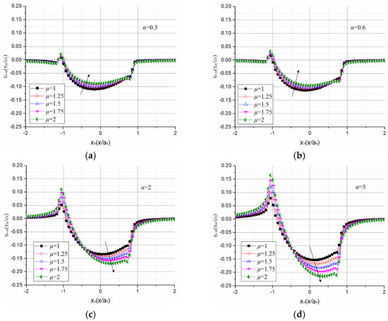
Figure 12.
τn−xz along the intersecting line of plane xoz and interface with various α and μ when h/ah = 0.02, ζ = 0.5, f = 0.1. (a) With various μ at α = 0.3; (b) with various μ at α = 0.6; (c) with various μ at α = 2; (d) with various μ at α = 3.
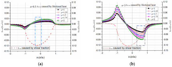
Figure 13.
Distributions of thermally induced and tangential traction caused interfacial shear stresses for different α. (a) Direction of thermally induced interfacial shear stress is opposite to that caused by tangential traction when α < 1; (b) Direction of thermally induced interfacial shear stress is same as that caused by tangential traction when α > 1.
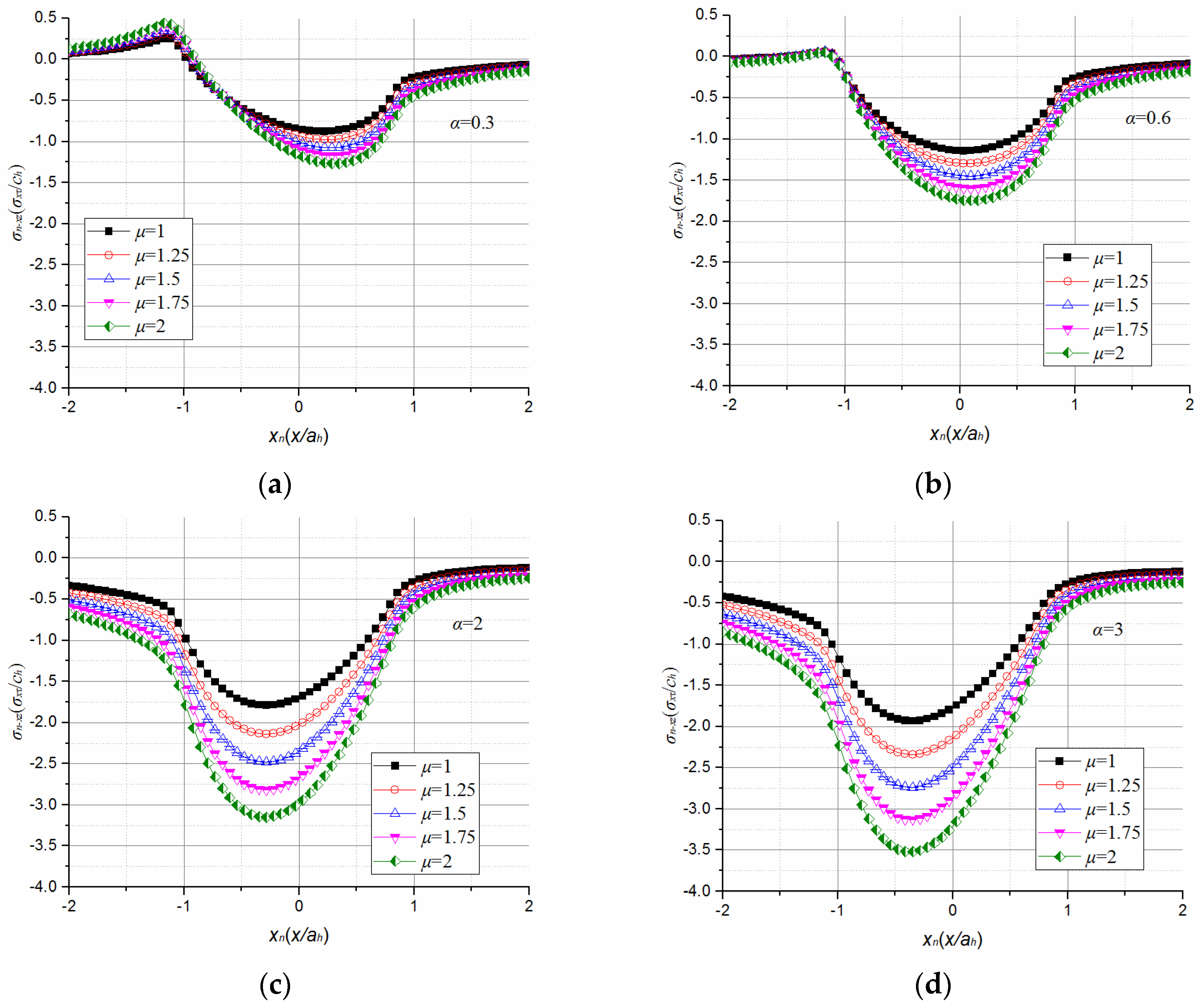
Another revealed feature is the effects of a coatings’ elastic modulus and thermal expansion coefficient on the tensile transverse stress along the intersecting line of plane xoz and the interface, as shown in Figure 14, with variations of α and μ at h/ah = 0.02, ζ = 0.5, and f = 0.1. Figure 14b–d indicate that coatings with a thermal expansion coefficient of α > 0.6 may render the interfacial transverse stress σn−xx compressive within the contact area on the interface for variations of μ, counteracting, in general, the brittle failure of the coating.

Figure 14.
σn−xx along the intersecting line of plane xoz and interface with various α and μ when h/ah = 0.02, ζ = 0.5, f = 0.1. (a) With various μ at α = 0.3; (b) with various μ at α = 0.6; (c) with various μ at α = 2; (d) with various μ at α = 3.
Thus, in order to obtain a lower interfacial shear stress and compressive transverse stress at the same time, 0.6 < αc/αs < 1 can be recommended as the goal in order to optimize the thermoelastic properties of thin hard coatings.
3.4. Effect of a Coating’s Thermal Conductiveness and Thermal Expansion Properties on Interface Stress Distribution
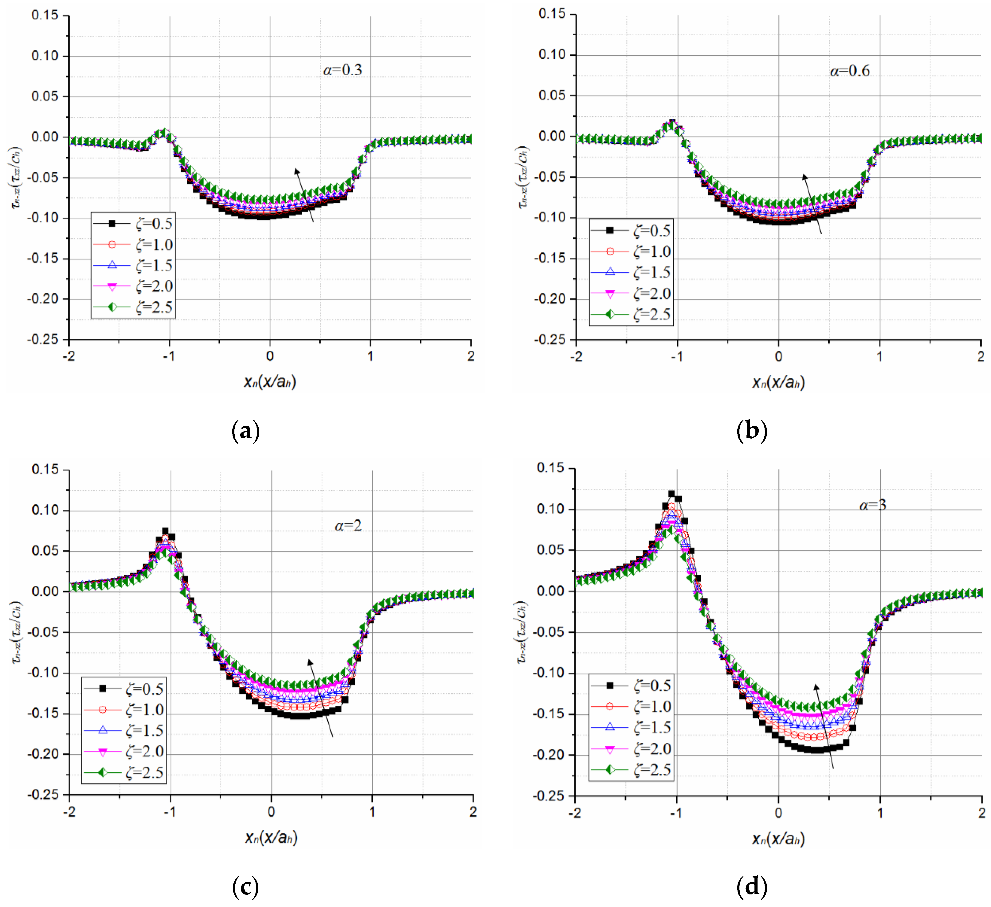
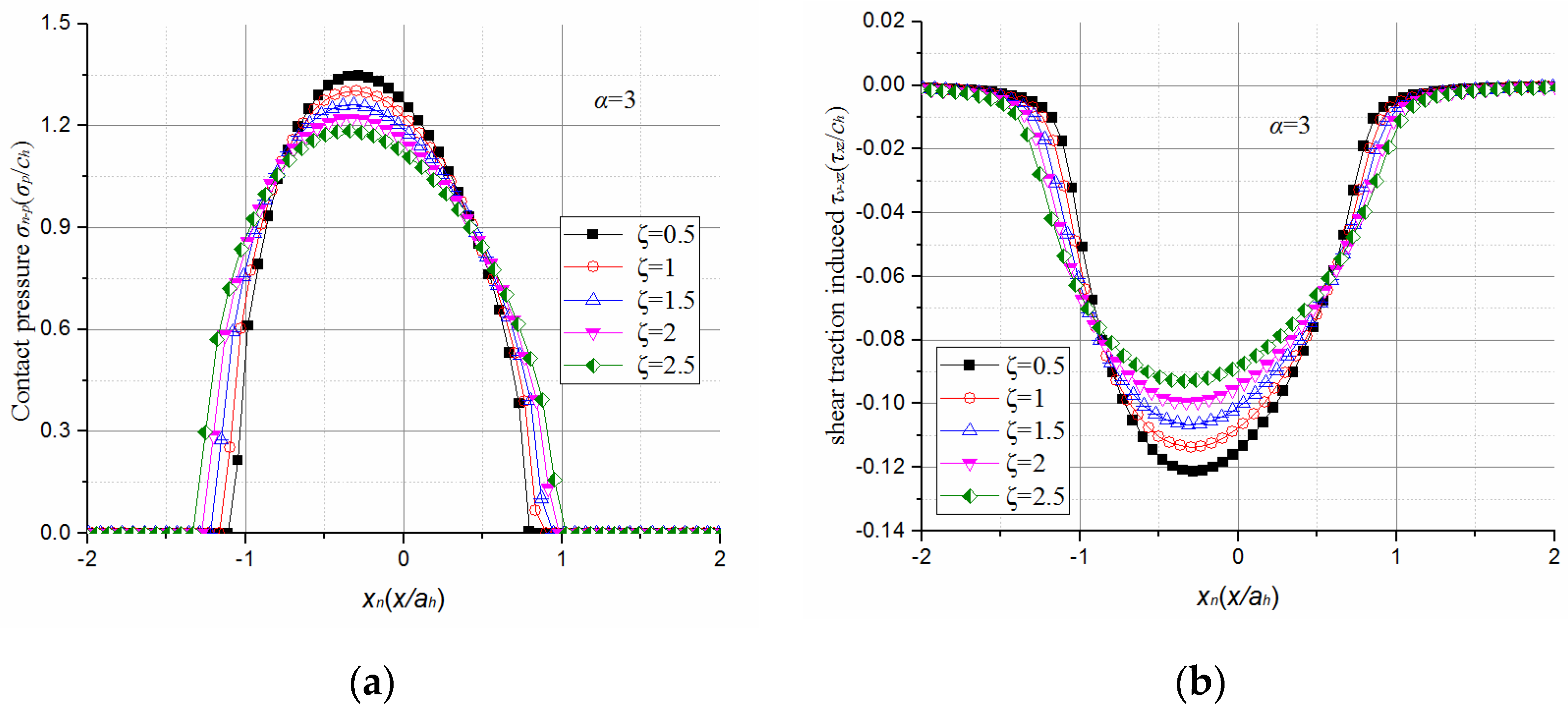
The effects of a coatings’ thermal conductive ratio, ζ, on shear stress τn−xz along the intersecting line of plane xoz and the interface are shown in Figure 15, with variations of α at h/ah = 0.02, μ = 2, and f = 0.1. The results shown in Figure 15 confirm that the increase in the thermal conductive coefficient of a coating is always beneficial in reducing the interfacial shear stress. As mentioned above, contact pressure distribution is co-determined by contact load and surface temperature rise in thermoelastic contact conditions. Figure 16 illustrates that the increase in ζ results in decreases in contact pressure and interfacial shear stress. With respect to Figure 16a, the magnitude of the contact pressure grows in an inverse proportion to ζ, and the magnitude of the contact area is proportional to ζ. The fact that coatings with a higher thermal conductivity can facilitate heat transfer within a coated system is understood to be accountable for contact pressure relaxation. With the dispersing of surface shear traction, interfacial shear stress decreases substantially, as shown in Figure 16b.
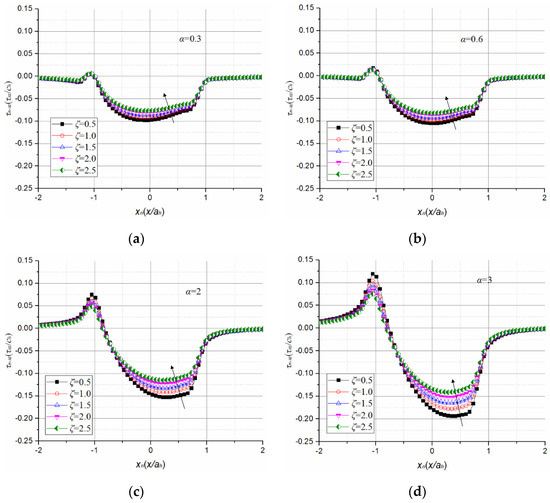
Figure 15.
τn−xz along the intersecting line of plane xoz and interface with various α and ζ when h/ah = 0.02, μ = 2, and f = 0.1. (a) with various ζ at α = 0.3; (b) with various ζ at α = 0.6; (c) with various ζ at α = 2; (d) with various ζ at α = 3.
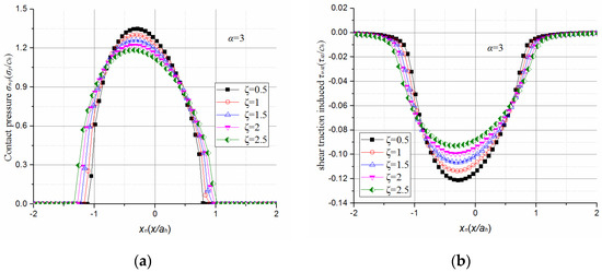
Figure 16.
Effect of ζ on the contact pressure and interfacial shear stress component, caused by friction force. (a) Increase in ζ results in decreases in contact pressure; (b) Increase in ζ results in decreases in interfacial shear stress component, caused by friction force.
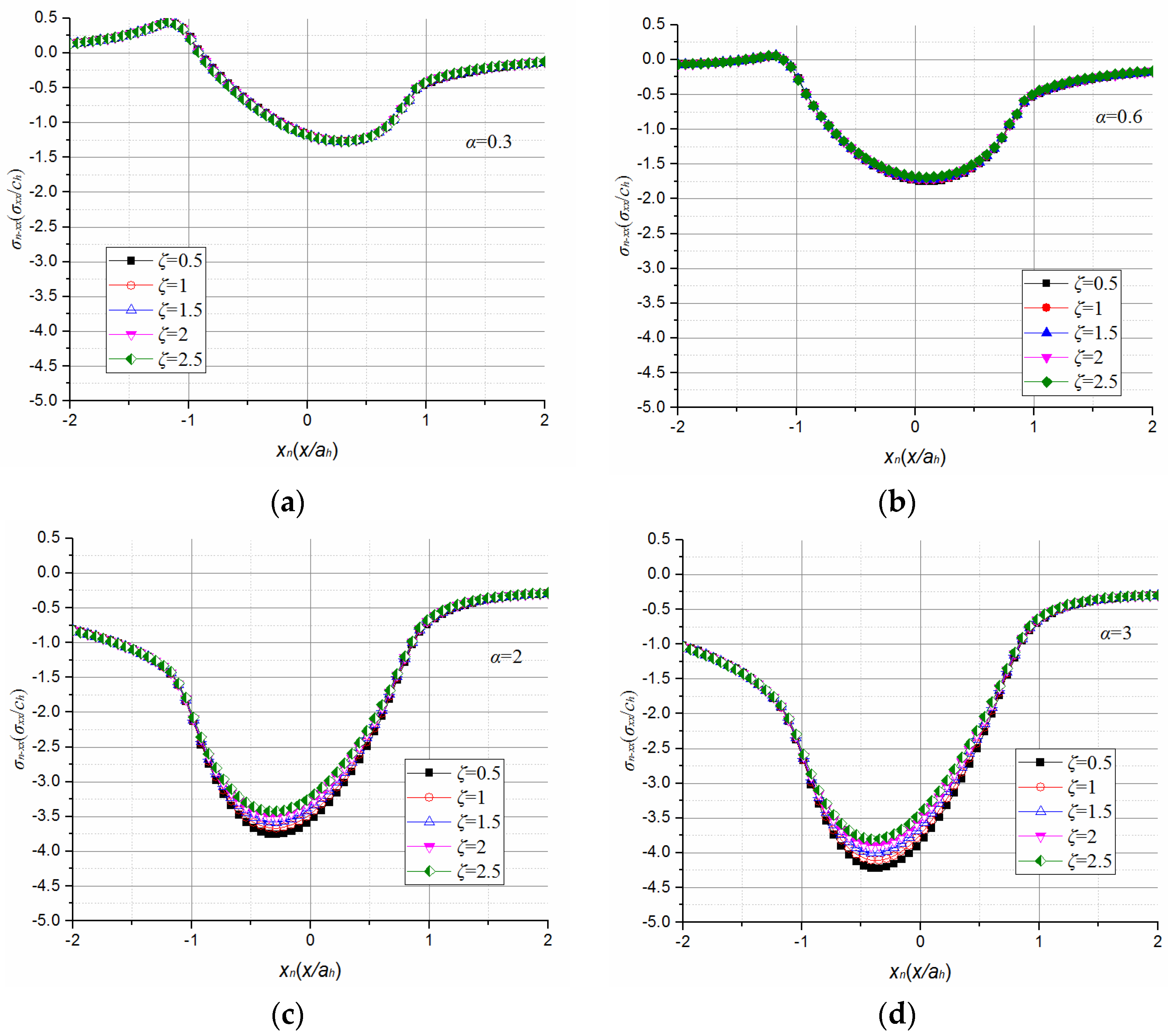
The effects of a coatings’ thermal conductive coefficient and thermal expansion coefficient on the tensile transverse stress along the intersecting line of plane xoz and the interface are provided in Figure 17, with variations of α and ζ at h/ah = 0.02, μ = 2, and f = 0.1. Figure 17a–d indicate that the dependence of interfacial tensile transverse stress on the variations of ζ is negligible.
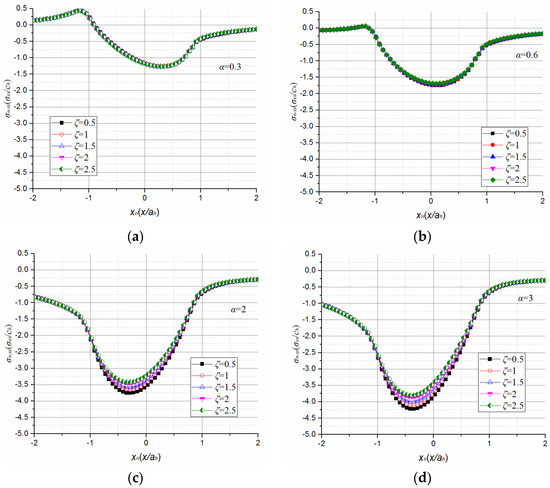
Figure 17.
σn−xx along the intersecting line of plane xoz and interface with various α and ζ when h/ah = 0.02, μ = 2, and f = 0.1. (a) With various ζ at α = 0.3; (b) with various ζ at α = 0.6; (c) with various ζ at α = 2; (d) with various ζ at α = 3.
Thus, in order to obtain a lower interfacial shear stress and compressive transverse stress at the same time, a higher value of ζc/ζs can be recommended in order to improve the resistance to interfacial delamination of the coating material, when subjected to sliding contact with friction heat generation.
The quasi-static thermoelastic contact problem between a ball and a coated solid is discussed in the present study. The contact mode between the two bodies is assumed to be conformal, with coating and substrate all being isotropic and without defects on the interface. In considering those assumptions, the present model can be applied to the brittle coating–ductile substrate system, with the coating’s elastic modulus being greater than the elastic modulus of the substrate material. The diameter of the ball should be 20 times greater than the width of the contact area, and the velocity of the ball should be less than 100 m·s−1. The work present herein offers room for further viable and promising extensions. For instance, the assumptions made above could be relaxed to cover a broader range of applications. Moreover, in the sense that the frictional contact on the surface of a brittle coating may eventually give rise to damage patterns in the form of interface cracking, the feasible coupled crack/contact analysis in the brittle coating–ductile substrate system incorporating the contact-induced frictional heating effect would pose another interesting research topic of technological significance. Such issues need to be addressed and will be reported in forthcoming papers. The analytical work in this paper can help in the design of the coating–substrate system with a proper coating thickness to obtain a relative low interface stress. In addition, the analytical work in this paper can propose targets on the modification of the coating material in elastic and thermoelastic properties. In the sense that the thermoelastic properties of the coating material have effects on the loading bearing capacity of the coating–substrate system. Tribology tests, such as the ball-on-disk test, with relative velocity being similar to real working conditions, could be applied to study the load bearing capacity of the coating–substrate system due to its reflecting the real thermal load condition and contact condition well.
4. Conclusions
This paper investigated the interfacial mechanical characteristics of a hard coating/substrate system, which was involved in a thermoelastic contact. The image point method and interface mechanics were employed in order to obtain Green’s functions for a normal load, tangential load, and thermal load. Based on Green’s functions and the contact mechanics, the temperature field and stress field were obtained with a high degree of accuracy. The effects of coating thickness, friction coefficient, and thermoelastic properties on the interfacial stress characteristics were discussed. It was found that:
- Adequate design of coating thickness for different friction coefficients can be help in obtaining relatively low interfacial shear stress and tensile transverse stress at the same time. For brittle coatings (Ec > Es), in the case where the friction coefficient is less than 0.1, a smaller coating thickness, with h/ah < 0.02, is recommended. With a friction coefficient between 0.1 and 0.3, a coating with a thickness h/ah of about 0.1 is proposed. When the friction coefficient is greater than 0.3, coating with a thickness h/ah above 0.25 is preferable.
- Interfacial shear stress tends to be relieved by frictional heating in the case of αc/αs < 1 for brittle coatings. Meanwhile, tensile transverse stress on the interface tends to be eliminated in the case of αc/αs > 0.6. A thermal expansion coefficient ratio of 0.6 < αc/αs < 1 can be recommended as a goal for the optimization of thin hard coatings-substrate systems.
- Coating materials with enhanced thermal conductivity are shown to lower surface contact pressure concentration, and, thus, decrease interfacial shear stress. Although the interfacial tensile transverse stress is affected, to a negligible extent, by the variations of the thermal conductive coefficient of coating materials, it is predictable that the increased thermal conductivity of a coating could improve the resistance to interfacial delamination of the coating material.
Finally, we believe that this paper provide an understanding of the mechanism of modifying interfacial failure for hard coatings by employing adequate analysis.
Acknowledgments
This work was supported by the National Natural Science Foundation of China (Grant No. 51275125) and the National Basic Research Program of China (Grant No. 2013CB632305).
Author Contributions
Chongyang Nie contributed the analysis software. Le Gu, Liqin Wang, and Chuanwei Zhang contributed to the helpful discussion of interfacial mechanics. Chi Zhang analyzed the calculation results and wrote the paper.
Conflicts of Interest
The authors declare no conflicts of interest.
References
- Ebert, F.J. Fundamentals of design and technology of rolling element bearings. Chin. J. Aeronaut. 2010, 23, 123–136. [Google Scholar] [CrossRef]
- Tong, Y.X.; Wang, L.Q.; Gu, L. Friction and wear behaviors of Si3N4 sliding against M50 bearing steel in vacuum. Adv. Mater. Res. 2010, 97, 1681–1684. [Google Scholar] [CrossRef]
- Wang, L.Q.; Li, C.; Zheng, D.Z.; Gu, L. Nonlinear Dynamics Behaviors of a Rotor Roller Bearing System with Radial Clearances and Waviness Considered. Chin. J. Aeronaut. 2008, 21, 86–96. [Google Scholar]
- Daisuke, Y.; Richard, J.C.; Peter, A.D. Wear mechanisms of steel roller bearings protected by thin, hard and low friction coatings. Wear 2005, 259, 779–788. [Google Scholar]
- Bobzin, K.; Lugscheider, E.; Maes, M.; Gold, P.W.; Loos, J.; Kuhn, M. High-performance chromium aluminium nitride PVD coatings on roller bearings. Surf. Coat. Technol. 2004, 188, 649–654. [Google Scholar] [CrossRef]
- Nie, C.Y.; Zheng, D.Z.; Gu, L.; Zhao, X.L.; Wang, L.Q. Comparison of interface mechanics characteristics of DLC coating deposited on bearing steel and ceramics. Appl. Surf. Sci. 2014, 317, 188–197. [Google Scholar] [CrossRef]
- O’Sullivan, T.C.; King, R.B. Sliding contact stress-field due to a spherical indenter on a layered elastic half-space. ASME. J. Tribol. 1988, 110, 235–240. [Google Scholar] [CrossRef]
- Wang, Z.J.; Wang, W.Z.; Wang, H.; Dong, Z.; Hu, Y.Z. Partial slip contact analysis on three-dimensional elastic layered half Space. ASME. J. Tribol. 2010, 132, 280–290. [Google Scholar] [CrossRef]
- Liu, S.B.; Wang, Q.; Liu, G. A versatile method of discrete convolution and FFT (DC-FFT) for contact analyses. Wear 2000, 243, 101–111. [Google Scholar] [CrossRef]
- Cai, S.; Bhushan, B. A numerical three-dimensional contact model for rough, multilayered elastic/plastic solid surfaces. Wear 2005, 259, 1408–1423. [Google Scholar] [CrossRef]
- Kot, M. Contact mechanics of coating–substrate systems: Monolayer and multilayer coatings. Arch. Civ. Mech. Eng. 2012, 12, 464–470. [Google Scholar] [CrossRef]
- Komvopoulos, K. Finite element analysis of a layered elastic solid in normal contact with a rigid surface. ASME. J. Tribol. 1988, 110, 477–485. [Google Scholar] [CrossRef]
- Kral, E.R.; Komvopoulos, K.; Bogy, D.B. Finite Element Analysis of Repeated Indentation of an Elastic-Plastic Layered Medium by a Rigid Sphere, Part I: Surface Results. ASME. J. Appl. Mech. 1995, 62, 20–28. [Google Scholar] [CrossRef]
- Ye, N.; Komvopoulos, K. Three-dimensional finite element analysis of elastic–plastic layered media under thermomechanical surface loading. ASME. J. Tribol. 2003, 125, 52–59. [Google Scholar] [CrossRef]
- Yang, J.; Komvopoulos, K. Dynamic indentation of an elastic–plastic multilayered medium by a rigid cylinder. ASME. J. Tribol. 2004, 126, 18–27. [Google Scholar] [CrossRef]
- Liu, J.; Ke, L.L.; Wang, Y.S. Two-dimensional thermoelastic contact problem of functionally graded materials involving frictional heating. Int. J. Solids Struct. 2011, 48, 2536–2548. [Google Scholar] [CrossRef]
- Choi, H.J.; Paulino, G.H. Thermoelastic contact mechanics for a flat punch sliding over a graded coating/substrate system with frictional heat generation. J. Mech. Phys. 2008, 56, 1673–1692. [Google Scholar] [CrossRef]
- Neha, S.; Kumar, N.; Dash, S.; Das, C.R.; Subba, R.R.V.; Tyagi, A.K. Scratch resistance and tribological properties of DLC coatings under dry and lubrication conditions. Tribol. Int. 2012, 56, 129–140. [Google Scholar]
- Singh, R.K.; Tilbrook, M.T.; Xie, Z.H. Contact damage evolution in diamond-like carbon coatings on ductile substrates. J. Mater. Res. 2008, 23, 27–36. [Google Scholar] [CrossRef]
- Moorthy, V.; Shaw, B.A. An observation on the initiation of micro-pitting damage in as-ground and coated gears during contact fatigue. Wear 2013, 297, 878–884. [Google Scholar] [CrossRef]
- Shahsavari, S.; Desouza, A.; Bahrami, M.; Erik, K.E. Thermal analysis of air-cooled PEM fuel cells. Int. J. Hydrogen Energy 2012, 37, 18261–18271. [Google Scholar] [CrossRef]
- Johnson, K.L. Contact Mechanics; Cambridge University Press: Cambridge, UK, 1985; pp. 171–193. [Google Scholar]
- Wang, T.J.; Wang, L.Q.; Gu, L.; Zheng, D.Z. Stress analysis of elastic coated solids in point contact. Tribol. Int. 2015, 86, 52–61. [Google Scholar] [CrossRef]
- Xu, J.Q.; Mutoh, Y. Analytical solution for interface stresses due to concentrated surface force. Int. J. Mech. Sci. 2003, 45, 1877–1892. [Google Scholar] [CrossRef]
- Hou, P.F.; Jiang, H.Y.; Tong, J.; Xiong, S.M. Study on the coated isotropic thermoelastic material based on the three-dimensional Green’s function for a point heat source. Int. J. Mech. Sci. 2014, 83, 155–162. [Google Scholar] [CrossRef]
- Xu, J.Q. Interface Mechanics; Science Press: Beijing, China, 2006; pp. 70–80. [Google Scholar]
- Grylitsky, D.V.; Pauk, V.J. Some quasistationary contact problem for half-space involving heat generation and radiation. Int. J. Eng. Sci. 1995, 33, 1773–1781. [Google Scholar] [CrossRef]


© 2017 by the authors. Licensee MDPI, Basel, Switzerland. This article is an open access article distributed under the terms and conditions of the Creative Commons Attribution (CC BY) license ( http://creativecommons.org/licenses/by/4.0/).