Abstract
Cold spray is a unique coating technology that allows for solid state deposition of particles under atmospheric pressure. In this paper, a three dimensional, Computational Fluid Dynamics (CFD) multicomponent model is developed to estimate cold spray gas conditions involving both nitrogen and air. Calibration of the model followed by validation is accomplished by considering the thermal history of substrate exposed to cold spray supersonic jet. The developed holistic multicomponent model is effective in determining the state of gas and particles from injection point to the substrate surface with the advantage of optimizing very rapid cold spray deposition in nanoseconds. The validation of k-ε type CFD multicomponent model is done by using the temperature measured for a titanium substrate exposed to cold spray nitrogen at 800 °C and 3 MPa. Heat transfer and radiation are considered for the de Laval nozzle used in cold spray experiments. The calibrated multicomponent model has successfully estimated the state of propellant gas for the chosen high pressure and high temperature cold spray conditions. Moreover, the multicomponent model predictions are in good agreement with a previous holistic three dimensional cold spray model in which only nitrogen was used as the surrounding as well as the propellant gas.
1. Introduction
The Cold Spray process is a rapidly emerging solid state deposition technology where the powder particles are deposited via supersonic velocity impact at a temperature much below the melting point of the spray material. The basic principle of the cold spray process includes a high velocity (300 to 1500 m/s) supersonic gas (air, nitrogen or helium) jet, established using a de Laval or similar converging/diverging nozzle. This supersonic jet is then used to accelerate the powder particle (5 to 50 µm) and spray them onto a substrate, located at a certain distance called stand-off distance. Generally, stand-off varies between 10 mm and 40 mm. Figure 1 shows the basic principle of cold-gas spray process.
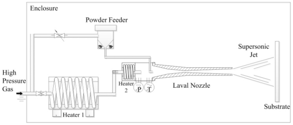
Figure 1.
Schematic diagram of cold spray system [1].
The high speed of the particles rather than high temperature causes particles to plastically deform on impact and form splats, which bond together to produce coatings. This plastic deformation reduces or avoids many shortcomings associated with traditional thermal spray techniques such as high-temperature oxidation, melting, crystallization, evaporation, residual stresses, gas release etc. The cold spray process was originally developed in the mid-1980s at the Institute of Theoretical and Applied Mechanics of the Russian Academy of Sciences in Novosibirsk by Dr. Anatolii Papyrin and his colleagues [2]. This research team worked on the design of high-speed “re-entry vehicles” and during the experiments, using a supersonic wind tunnel with metal tracer particles, they observed that sometimes the particles build up a coating on the target instead of eroding it [3]. This accidental deposition phenomenon during wind tunnel experiments formed the basis on which further study on cold spray deposition was carried out. A US patent was issued in 1994, and the European patent in 1995.
Study of the cold spray process with the assistance of a numerical model is beneficial because of complex thermo-mechanical events occurring in nanoseconds during the deposition. Currently, a numerical approach is gaining much attention in cold spray studies. Li et al. [4] numerically investigated the cold spray process by introducing under-expanded and over-expanded jets. They proposed a normal shock model to estimate the cold spray powder particle impact speed by analyzing nozzle exit conditions. Stoltenhoff et al. [5] utilized both one-dimensional numerical model and extensive cold spray experiments to study the cold spray process and its coatings. Their study proposed that for a spherical copper powder, the critical velocity determined was 570 m/s in the presence of low oxygen content. The developed Fluent CFD code was based on the concept of critical velocity, and the deposition efficiency can be extended to the calculation of different nozzle geometries, carrier gases and parameter settings.
Karimi et al. [6], successfully developed the computational fluid dynamics model of the cold gas dynamic spray process to simulate the gas flow and powder particle trajectories in an oval shaped supersonic nozzle before and after the impact with the targeted surface. A two dimensional cold spray numerical model suggested by Xian-Jin et al. [7], demonstrated the state of in-flight powder particle in terms of velocity and temperature in low-pressure cold spray process. They utilized implicit Fluent CFD code to simulate the supersonic gas flow for nitrogen and helium gas. For solving turbulence in flow RNG k-ε model was used. The model predicted the temperature of particle in supersonic gas flow satisfactorily and can provide an important reference for low-pressure cold spray process within limited constraints. Yin et al. [8], reported the calculation method for modeling multi-particle impact process in cold spraying. They conducted the comparative study between Lagrangian, Eulerian and smoothed particle hydrodynamics (SPH) methods in detail to discuss multi-particle impacts and bond formation. They simulated and studied particle deformation behavior in 2D and 3D using an explicit LS-DYNA program. Their simulation results revealed that Lagrangian method significantly depends upon the meshing size and the element type for multi-particle impact. The Eulerian method outcome was close to the experimental data and can be regarded as superior to the other ones. However, mesh-free SPH method showed reasonable results in particle deformation behavior and the weight of independent SPH particle imply limited effects on the output. Samareh et al. [9], presented a three dimensional model of cold spray process by analyzing the effect of substrate location and shape. They utilized Fluent® code to identify the effect of substrate geometry. In that study the particle landing location on the substrate, the effect of stand-off distances and the particle normal impact velocity were investigated. As per their findings, the optimum location for the substrate is 10 mm from the nozzle exit particularly in the case when cold spray nozzle is operated at low pressure. Moreover, this study reveals that particle dispersion is less when cylindrical substrate is used instead of flat rectangular substrate.
Recently, Zahiri et al. [1], proposed a holistic three dimensional CFD model for cold spray supersonic jet which includes a cold spray gas particularly nitrogen, utilizing two equation k-ε turbulence model from injection point to the surface of substrate. In this study, the simulation results were compared with experimental data to validate the model estimation. The 3D model was mainly calibrated against titanium substrate temperature recorded during the experiment. The study revealed that the 3D model was in good agreement with experimental data in terms of temperature values and the model prediction of cold spray gas velocity and pressure were satisfactory.
In this paper, the preliminary study of cold spray multicomponent 3D model is further extended and developed to couple nitrogen with surrounding air. It is believed that the holistic multicomponent model will then be a close approximation of cold spray process in reality. The developed multicomponent model is calibrated against the experimental results of Zahiri et al. [1], in which the thermal history of titanium substrate was recorded. It is interesting to learn that the developed multicomponent model also exhibited good agreement with the experimental data. Details of model development are described in later sections of this paper. It is important to mention that three dimensional multicomponent model would be beneficial in predicting the state of cold spray powder holistically from injection point, at nozzle throat, at nozzle exit and also at just before the impact on the surface of substrate. With such calibrated and validated three dimensional multicomponent model, it would be possible to study the particle deposition behavior and post deposition residual stresses generated in the coatings.
2. Numerical Modeling
A two-equation k-ε type Reynold Average Navier Stoke (RANS) model is selected to develop three dimensional numerical multicomponent model. The benefit of using k-ε turbulence model is its robustness and flexibility to maintain optimum computation time as compared to other turbulence models such as shear stress transport (SST), normal velocity relaxation model (v2-f) or normal velocity relaxation model and large eddy simulation (LES). Zuckerman and Lior, 2006 [10], presented a comprehensive comparative study about the numerical modeling techniques used in supersonic jet impingement process. Normal velocity relaxation turbulence model (v2-f) has been declared as the most reliable method for solving turbulence in fluid flow but at very high computational cost. This is in contrast to 15%–60% acceptable error for k-ε model with the most cost effectiveness in terms of computational time and hardware requirements. ANSYS® CFX® release 14.5, an implicit CFD software was chosen to develop the 3D multicomponent model for cold spray process. ANSYS® CFX® is a widely used tool to develop various CFD based models with optimized computation time.
2.1. Governing Flow Equations
The flow in cold gas dynamic spray is considered as steady-state supersonic turbulence flow with heat transfer during the process. The selected CFD program solves the Navier-Stokes equations for compressible flow. The governing equations are continuity equation, momentum equation and total energy equation. The principle continuity equation is described in detail as Appendix. For multicomponent model, transport equations are solved for velocity, pressure, temperature and other quantities of the fluid. Additional equations must be solved to determine how the components of the fluid are transported within the fluid. Therefore continuity equation for multicomponent flow, after Reynolds-averaging can be expressed as:
where is the mass-average density of fluid component i in the mixture, that is the mass of the component per unit volume, is the mass-average velocity field, is the mass-average velocity of fluid component i, is the relative mass flux and Si is the source term for component i. The modification in relative mass flux term for multicomponent flow is described in Appendix.
Mass fraction of component i can be defined as:
It is important to mention here that the sum of the component mass fraction of overall components contributing in a multicomponent flow is 1. Equation (1) after incorporating multicomponent index and mass flux can be re-written as:
The momentum equation is given by:
where p' is the modified pressure which includes an additional term due to turbulence normal stress, μeff is the effective viscosity responsible for turbulence, SM is the sum of body forces.
The k-ε model realizes that turbulence viscosity is linked to the turbulence kinetic energy and dissipation via the relation:
where Cμ is a constant, k is the turbulence kinetic energy and it is defined as the variance of the fluctuations in velocity. ε is known as the turbulence dissipation rate at which velocity fluctuates. Both k and ε values can be computed directly from the differential transport equation for turbulence kinetic energy and turbulence dissipation rate, which are expressed as:
where k and ε dimensions are (m2/s2) and (m2/s3) respectively. Cε1 and Cε2 are the turbulence constants. Standard values of turbulence constants Cε1, Cε2 are 1.44 and 1.92 respectively for turbulent flow [11,12]. In a recent study, Zahiri et al. [1], identified and emphasized the direct effect of these constants on turbulence production and turbulence eddy dissipation in a supersonic flow for cold spray process. After calibrating a numerical model with experimental data, they suggested calibrated values of Cε1 and Cε2 as 1.65 and 2.30, respectively for cold spray process. Pk is the turbulence production due to viscous forces, which is modelled using the equation,
For compressible flow, is large only in regions with high velocity divergence, such as at shocks regions [13].
The equation for total energy or total enthalpy (htot) modified for Reynolds average energy equation is given by:
where Prt is the turbulent Prandtl number. Total enthalpy refers to the total energy of the system including viscous work. Therefore, total enthalpy is given by:
where U is the flow velocity with static temperature calculated using static enthalpy. The static enthalpy computation and working formula have been explained in Appendix. Considering the mass fraction Equation (2) for component i, the transport equation for turbulent kinetic energy can be modified in multicomponent flow as:
Within solid domains, the conservation of energy equation can account for heat transport due to conduction, and is given by:
where h, ρ and λ are the enthalpy, density and thermal conductivity of the solid material, respectively.
The ANSYS™ CFX Solver® with general grid interface (GGI) was utilized to allow heat transfer across the wall interface. At GGI, the gas-side and the solid-side temperatures were calculated based on the heat flux conservation.
2.2. Computational Domain and Boundary Conditions
For computational domain, typical geometry of cold spray multicomponent model is shown in Figure 2. In Figure 2a, the cold spray multicomponent model geometry comprises of convergent-divergent de Laval nozzle carrying high pressure nitrogen and the substrate was modeled as 70 mm × 70 mm × 5 mm square flat plate of titanium with an assumption of zero surface roughness were shown. The surrounding domain is modelled as a cylindrical domain with 400 mm diameter and 361.5 mm length are also visible in Figure 2a. To solve 3D multicomponent model numerically, ANSYS™ CFX Solver® v14.5 was used. The selected Computational Fluid Dynamics (CFD) tool is commercially available and economically viable to carry out supersonic CFD analysis with optimum accuracy. It is worthwhile to mention here that for calibration purposes the numerical model boundary conditions, dimensions of nozzle and the stagnation zone dimension were chosen to be identical to a commercially available, Type 27 TC, nozzle manufactured for a KINETIK® 4000 (Sulzer Metco, Zurcherstrasse, Winterthur, Switzerland) cold spray system. The current Type 27 TC cold spray nozzle had a 2.7 mm throat diameter and 8.5 mm exit diameter as shown in Figure 2b.
At inlet, a total pressure ptot as a boundary condition was considered. Figure 3d shows the pre-chamber plane of high pressure gas domain which serves as an inlet and where an inlet boundary condition has been applied for getting a better convergence rate. The direction of the inlet velocity vector was normal to the boundary. By definition, the total pressure is a pressure that would exist at a point if the fluid was brought to rest instantaneously such that the dynamic energy of the flow converted to pressure without any loss [14,15]. The inlet turbulence quantities, k and ε were calculated based on default inlet turbulence intensity (I = u/U = 0.037), which was an approximate value for internal cylinder flow, and turbulence auto-computed length scale, and are given by,
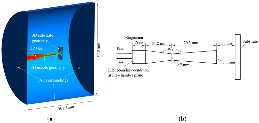
Figure 2.
(a) Three dimensional representation of cold spray tungsten-carbide nozzle, high pressure nitrogen gas, titanium substrate and surrounding air domains; (b) Schematic diagram of cold spray nozzle including dimensions.
The total temperature Ttot as a boundary condition was also defined at inlet boundary of high pressure gas domain. It is the temperature obtained by decelerating the flow to a zero velocity [6]. The inlet energy flow by diffusion was assumed to be negligible compared to advection and equated to zero. The total temperature is given by
where Tstat is the static temperature which is a thermodynamic temperature and depends on the internal energy of the high pressure gas. U and cp are the velocity and specific heat at constant pressure, respectively.
For the surrounding air domain, the opening boundary conditions were set because it allowed the gas to cross boundary surfaces in either direction. Free-slip wall boundary condition was chosen to define interaction between gas and solid walls, which were assumed to be frictionless [1,16]. In this condition, the velocity component parallel to the wall was computed and had a finite value, but the velocity normal to the wall, and the wall shear stress, were both set to zero. In previous studies [17], free-slip condition was used to interpret the physical behavior of particle-wall interaction in turbulent flow. The adiabatic wall boundary condition was specified for nozzle pre-chamber inlet plane. Its purpose was to prevent heat transfer across the wall boundary. The mechanical and thermal properties of nozzle and the substrate were assumed to be isotropic.
A thin nano-meter oxide layer is expected to form naturally on the surface of titanium substrate as identified in earlier studies [18]. However, for three dimensional model analyses, it is insignificant due to its very small thickness [1] and is negligible. All the governing equations of the flow and the boundary condition at the walls, inlet and surrounding domains are summarized in Table 1.

Table 1.
CFD analysis flow and boundary conditions.
| Quantity | Classification | Condition |
|---|---|---|
| Flow | a. Heat Transfer | a. Total energy |
| b. Turbulence model | b. k-ε two equation turbulence model | |
| Boundary Conditions | a. Inlet | a. Total pressure, Total temperature |
| b. Surrounding | b. Opening at ambient temperature | |
| c. Walls | c. Free-Slip (frictionless) | |
| d. Solid nozzle and substrate interface with fluid | d. Monte Carlo Radiation model |
2.3. Domain Meshing
The meshing for all domains in a multicomponent model has been performed using ANSYS™ ICEMCFD® v14.5 with blocking method. The hexahedral mesh elements approach was adopted to develop an acceptable structured mesh for both fluid and solid domains in a CFD model as shown in Figure 3a. An optimized mesh with less number of mesh elements was suggested to carry out analysis for cold spray supersonic jet turbulence. The idea behind this approach was to reduce simulation computation time with minimum accuracy loss. Since the model needs to be calibrated and validated against experiment results therefore, an increase in number of mesh elements at the cost of increasing computation time would not be suitable. A mixture of different sizes of mesh elements were brought together depending upon the location where high accuracy results were expected. These regions were magnified and identified as nozzle throat as shown in Figure 3b, supersonic jet expansion zone at nozzle exit and the jet impingement zone in front of the substrate as shown in Figure 3c. The element size of 0.06 mm to 0.2542 mm was selected for throat area to cater for rapid changes at nexus of de Laval nozzle convergent-divergent plane during the flow, which was higher than in previous investigation [1]. An inflation layers with y-plus of about 11 was used at near wall boundaries [1,15]. The mesh size in other domains was large as compared to the throat to further reduce the overall computation time of three dimensional model. The developed mesh for three dimensional multicomponent model demonstrated satisfactory estimation and was in good agreement with experimental outcome providing reduction in simulation time. The computation time was reduced to a couple of days from several weeks in case of using small size mesh elements.
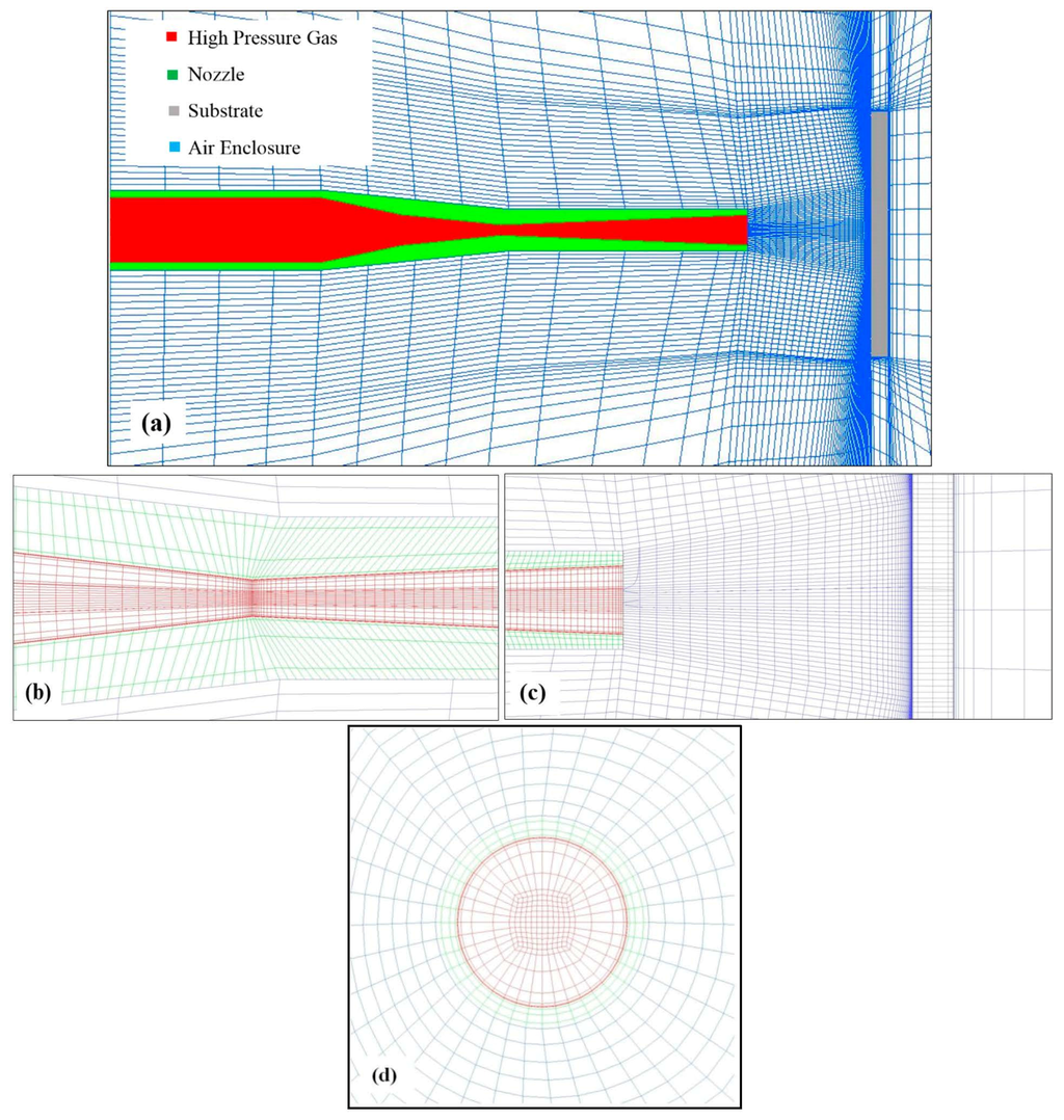
Figure 3.
Developed mesh for solid and fluid domains (a) complete CFD three dimensional computational grid; (b) cold spray convergent-divergent nozzle throat; (c) cold spray nozzle exit and substrate surface at 35 mm stand-off distance; (d) high pressure gas inlet plane.
3. Experimental Section
The experimental framework is described in a previous study by Zahiri et al. [1]. In this study, the CGT KINETIKS® 4000 (Sulzer Metco, Zürcherstrasse, Winterthur, Switzerland) commercial cold spray system was used for experimental work to achieve supersonic jet. The cold spray nozzle geometries were 51.2 mm converging section, 2.7 mm throat diameter, 70.3 mm diverging section and 8.3 mm exit diameter. The cold spray nozzle material was Tungsten Carbide (WC) which was held normal to the substrate surface with the assistance of an ABB IRB 2600 (ABB Ltd., Affolternstrasse, Zurich, Switzerland) robotic arm. A Grade 2 commercially pure (CP) titanium flat plate of size 70 mm × 70 mm × 5 mm was selected as substrate. The experiment was conducted with two sets of cold spray jet conditions; 550 °C, 1.4 MPa and 800 °C, 3 MPa as shown in Table 2.

Table 2.
Cold Spray conditions for calibration and validation of the developed multicomponent model.
| Cold Spray Condition | Temperature (°C) | Pressure (MPa) | Propellant Gas | Stand-off (mm) |
|---|---|---|---|---|
| 1 | 550 | 1.4 | Nitrogen | 35 |
| 2 | 800 | 3.0 | Nitrogen | 35 |
Five K-type thermocouples were placed diagonally on the substrate from rear side with 10 mm gap between adjacent thermocouples as shown in Figure 4. Temperature measurements were recorded using a Pico thermal data logger with a step size of 1 millisecond. The substrate was exposed to cold spray supersonic jet through the robot moving the nozzle to its position in front of substrate. The nozzle was rapidly moved away after substrate temperature reached to a steady state shown by thermal data logger. In that study, a special method was developed to determine the exact location of the cold spray supersonic jet on the surface of the substrate. The method was developed when it was observed that after completing the cold spray experiment, the center of the supersonic jet was not exactly located at the center of the substrate where thermocouple 1 was located. The comprehensive details regarding coordinates of each thermocouple in respect to jet center and the explanation of method determining the jet center can be found in earlier study [1]. For the purpose of this study and for the development of cold spray multicomponent model, few observations are shown in Table III obtained from Zahiri et al. [1].
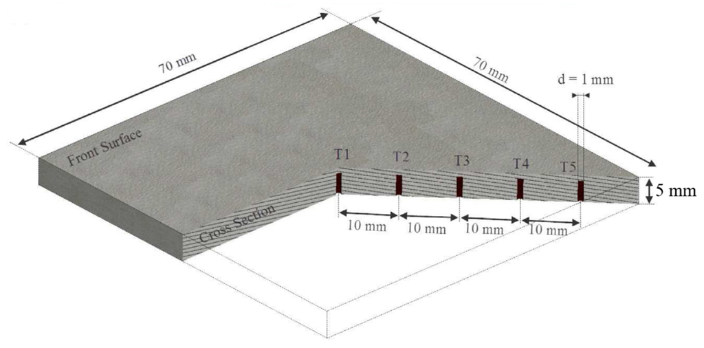
Figure 4.
Cross section of titanium substrate showing exact placement of diagonally oriented five K-type thermocouples from rear side [1].
4. Results
Table 3 shows the recorded temperature of cold spray experiment conducted at 550 °C and 1.4 MPa. It is evident from the data that highest temperature was recorded at thermocouple T1 which was located at the center of the substrate where the center of jet was expected. The lowest temperature was recorded at thermocouple T5 which is farthest from the center of the substrate when measured diagonally.
The developed multicomponent model revealed an interesting thermal profile on the surface of substrate, which will be discussed in following paragraphs.

Table 3.
Experimentally recorded average temperature for each thermocouple with respect to cold spray condition 1 [1].
| Thermal Couple Name | Distance from Substrate Center (mm) | Average Experimental Temperature (°C) |
|---|---|---|
| T1 | 0.00 | 204.24 |
| T2 | 10.00 | 178.42 |
| T3 | 20.00 | 96.87 |
| T4 | 30.00 | 83.75 |
| T5 | 40.00 | 35.87 |
The calibration of multicomponent model was carried out with cold spray condition 1 as shown in Table 2. Nitrogen as propellant gas at 550 °C and 1.4 MPa was used to cold spray with a supersonic jet impinging onto the substrate surface placed at 35 mm stand-off distance. For the numerical model, the substrate material properties were chosen as similar to the experiment specimen Grade 2 commercial purity titanium [1,19]. An initial domain temperature Tdom of 15 °C was set, which was similar to the cold spray laboratory temperature when experiments were conducted. In a multicomponent model, the environmental domain is comprised of natural air unlike in the previous single component model [1], in which nitrogen was chosen as environmental domain gas due to its major proportion in air. In the current multicomponent study, air is chosen for surrounding or environmental domain in order to develop the model close to reality. It is believed that exact interpretation of simulation model when compared to experimental set-up would assist in generating the data with a greater accuracy. In such a condition the developed model prediction will be more reliable, which is necessary for calibration of the model. An environment relative pressure of 1 atm, pdom = 1 atm was held constant over the three opening boundary surfaces, and the direction was taken to be normal the boundary plane.
A user defined time step function tstep based on a generic step function f(x) = 1 + tanhkx/2 [20], was considered instead of default automatic time scale in order to capture the rapid changes in gas conditions at initial stage of computation. The function was needed to be recomputed at the end of each time step for acquiring a fresh value for the next time step calculation as per the following equation [1].
where atstep was the accumulated simulation time step, tstepMIN was the minimum time step value, tstepMAX was the maximum time step value, α was the slope characteristics and β was the slope position.
It was discovered that a Prandtl number of 0.3 provides the minimal error percentage when simulation data was compared with experimental work. Previous studies suggested the value of Prandtl number to be 0.9 and 0.5 in turbulence modeling of fluid flow [15]. During the calibration of multicomponent model Prandtl number allowed for improved and effective heat transfer in the gas domain. Other variables were also reviewed and modified in the calibration process. In Table 4, the variables contributed in the calibration are summarized, which are similar to the previous study by Zahiri et al. [1].

Table 4.
Calibrated parameters for k-ε model.
| Turbulence Constants | Calibrated Value | Prandtl Number Pr |
|---|---|---|
| Cε1 | 1.65 | 0.30 |
| Cε2 | 2.30 | |
| Cµ | 0.09 | |
| CScale | 10.00 | |
| CClip | Kato Launder (KL) |
All pressure specifications were relative to the reference pressure Pref = 0 bar. It is worthwhile to mention that time steps below 1 × 10⁻⁷ s were optimized to achieve better convergence rate. It is worthwhile to mention here that this time step drastically reduced the computation time from several days to just one day when it was used with reduced number of mesh elements. The results were satisfactory when compared with experimental results.
As shown in Figure 5, the estimated temperatures for calibrated multicomponent model represent a close approximation when compared with experimental results. It shows that the chosen two equation k-ε turbulence model was reliable and satisfactory in simulating the complex cold spray process. Individually analyzing each thermocouple, the error for thermocouple T3 (36%) was the largest amongst other thermocouple. One of the reasons for this huge deviation could be the rapid variation in gas condition in the regime where T3 was located. Another reason could be the insufficient number of mesh elements in the zone where T3 was placed. Further study would be needed to understand this large difference in error approximation and mesh may be reviewed. Thermocouple T1 demonstrated the lowest 2% calibration error for estimation of temperature which forfeits the idea that two equation k-ε model was an appropriate approach to capture the turbulence near the jet center. It is important to mention here that thermocouple T2 showed 6% calibration errors which was also near the zone where jet center was expected. Zahiri et al. [1] have experimentally measured the maximum temperature (jet center) on the surface of substrate. In their study, a reliable mathematical and analytical model was presented to locate the cold spray jet center on a square shape substrate. It is worth mentioning here that the point of maximum temperature (jet center) can only be located if temperature is measured with a thermocouple placed in diagonal arrangement within one line. The maximum temperature of 235 °C [1] was measured experimentally for cold spray condition 1. The maximum temperature of 240 °C predicted by the calibrated 3D multicomponent model for the same cold spray condition 1, on the square substrate is in good agreement with the experimental data. This close agreement of 3D model predicted result with the experimental result verifies that the multicomponent model is a more realistic model to control operating parameters of the cold spray process. For both thermocouples T1 and T2, the calibration error percentage was within 10% which shows that the developed multicomponent model is a more realistic numerical model and is capable of predicting reliable outcome. The calibration error for thermocouple T4 and T5 were 13% and 15% respectively, which was due to the rapid heat transfer and decline in turbulence away from the jet center. The overall average error for the calibrated multicomponent model was 14% which was within 15% error range and was considerably lower than the theoretical 77% error for cold spray condition 1 as reported earlier [1].
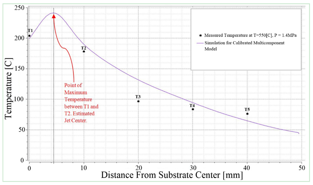
Figure 5.
Comparison of experimental results with calibrated 3D multicomponent model thermal outcome for all five thermocouples at 550 °C and 1.4 MPa cold spray conditions.
Figure 6 shows a three dimensional cross section of holistic temperature distributions of calibrated k-ε multicomponent model which comprised of cold spray nozzle, the supersonic jet, and titanium substrate for cold spray condition 1. As shown in Figure 6, the hot spot on titanium substrate is clearly visible and can be found just in front of the supersonic jet nozzle. The maximum temperature achieved on the titanium substrate was 240 °C and located at hot spot, the core of the jet. The divergent section of the cold spray nozzle reduced the jet temperature to 56% less as compared to the initial temperature of 550 °C which could be due to the presence of environment air maintained at ambient temperature of 15 °C. The calibrated outcome of multicomponent model is found to be in good agreement with earlier study [1]. These results reinforced the idea of carrying out the calibration of CFD modeling of cold spray jet which is close to reality and the same model can be further extended to learn more realistic events in cold spray process such as particle flow, particle deposition and residual stresses in the cold spray coating.
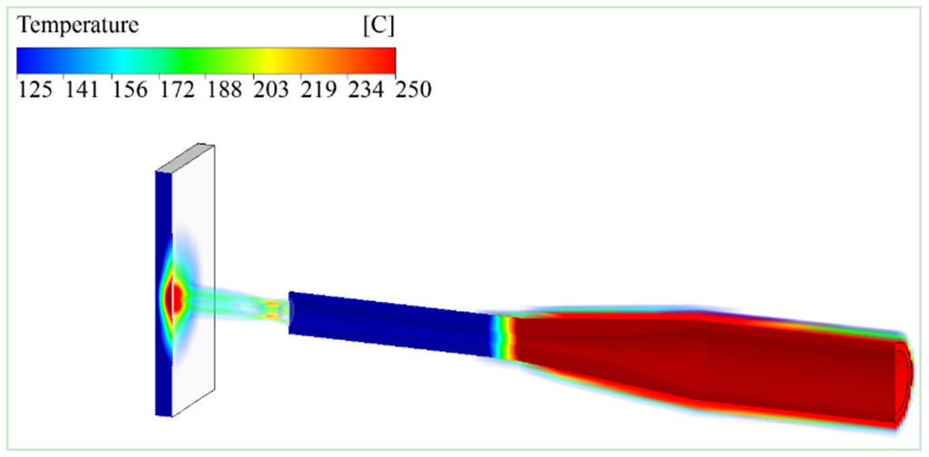
Figure 6.
Holistic estimation of temperature from gas injection point to the titanium substrate surface for cold spray conditions 550 °C and 1.4 MPa, using calibrated 3D multicomponent model.
5. Evaluation of the Model and Discussion
The validation of calibrated k-ε three dimensional multicomponent model was carried out by choosing cold spray condition 2 (Table 2) at higher temperature and pressure of 800 °C and 3 MPa respectively. The estimated temperature profile of cold spray condition 2 is shown in Figure 7. The developed three dimensional multicomponent model predicted temperatures well and in good agreement with experimental results for all five thermocouples. Considering the magnitude of error difference between cold spray condition 1 and 2, the developed 3D multicomponent model predicted well at higher temperature and pressure with negligible 1% variations in error. For condition 2, the overall average error of 15% was estimated for all thermocouples. A similar trend was observed in T3 estimating the highest difference of 34% with experimental results for the cold spray condition, which needs more investigation.
The maximum temperature of 438 °C was estimated at jet center impinging onto the substrate and it was located between thermocouple T1 and T2. The jet center temperature was estimated to be almost half of the inlet gas temperature. The validated multicomponent model temperature estimation of jet center, thermocouple T1 and thermocouple T2 were in good agreement with earlier study of single component model [1].
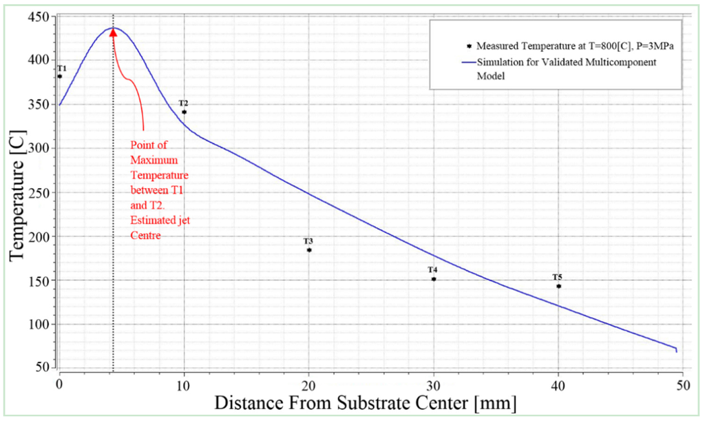
Figure 7.
Estimated temperature for cold spray conditions 800 °C and 3 MPa using 3D multicomponent model compared with experimental results for corresponding five thermocouples.
The holistic three dimensional temperature distribution of the validated multicomponent model is shown in Figure 8. The model predicted distribution of temperature within cold spray nozzle body, at throat, at nozzle exit and onto the surface of substrate. The overall thermal effect for cold spray condition 2 was higher than for the cold spray condition 1. The highest temperature was observed at the nozzle throat, which was in good agreement with earlier studies by Li et al. [21]. An earlier developed validated single component model also exhibited the aggressive thermal pattern around the nozzle body [1]. The three dimensional simulation results confirmed the presence of jet center on the surface of substrate.
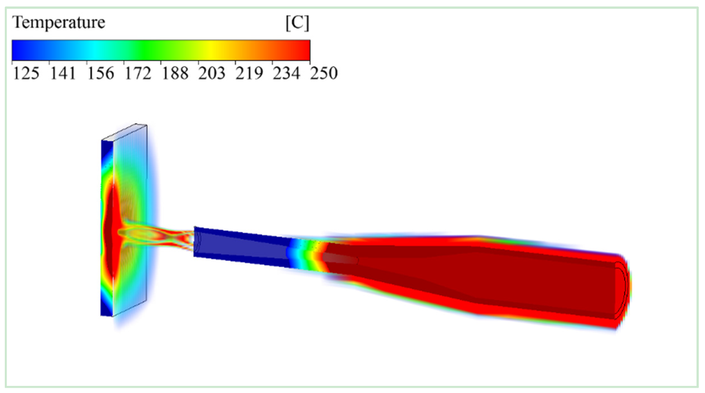
Figure 8.
Simulation of temperature distribution for cold spray supersonic jet at 800 °C and 3 MPa estimated holistically from nozzle stagnation zone to the substrate surface, predicted by 3D multicomponent model.
The maximum temperature estimated on the surface of substrate for the jet center as mentioned in the previous paragraph was 438 °C, which is clearly visible in three dimensional simulations. The information about this region can be utilized in the study of cold spray particle deposition and bond formation which can be further extended to the study of residual stresses. The study of temperature variations within the substrate was also previously experimentally investigated [21,22], and the validated multicomponent model results presented similar profile at the jet center showing a decline in temperature at the corner of the substrate away from the jet center. The lowest temperature 121 °C below 125 °C can be seen in Figure 7 and Figure 8.
The 3D multicomponent model holistic velocity distribution is shown in Figure 9. The maximum velocity at nozzle exit was estimated to be 1245 m/s, which was found to be below the velocity of 1303 m/s developed earlier in one dimensional model prediction [20]. Moreover, the multicomponent prediction for velocity was 65 m/s, less than the earlier developed holistic 3D single component model [1]. The reason for the decrease in the gas velocity at nozzle exit could be due to the presence of air molecules. The more comprehensive profile of gas velocity from nozzle pre-chamber to the surface of substrate can be found in Figure 10. The regions of de Laval nozzle are highlighted with clear identification of important zones within the nozzle. Inside the pre-chamber zone, the gas starts to accelerate in convergent section of the nozzle. At nozzle throat, due to reduction in area, the gas accelerates more and reaches to a maximum velocity of 1245 m/s at nozzle exit. Inman et al. [23] have experimentally measured the velocity of supersonic under-expanded impinging jets using laser-induced fluorescence method, which uses nitric oxide (NO) flow-tagging velocimetry. This technique utilized a single laser, single camera system in order to obtain the planar maps of the streamwise component of velocity. Further details of experimental setup can be found in reference [23]. The experimentally measured centerline velocity of 2.4 mm throat diameter nozzle at 557 K (284 °C) and 23.4 kPa (0.0234 MPa), near the nozzle exit was 800 m/s. The 3D multicomponent model estimation of 1245 m/s velocity at the nozzle exit can be considered to be a reasonable estimate when compared with the early reported experimental results. The difference is due to the fact that the operating temperature and pressure in 3D model were well above the reported experiment conditions. Moreover, the 3D model utilized 2.7 mm throat diameter nozzle and the nozzle exit diameter was also different. However, further investigation in terms of experimentation and modeling will be required in future work for more exact comparison and validation of developed multicomponent model. The substrate is placed at a standoff distance of 35 mm, and therefore, for the area between nozzle exit and surface of substrate, due to the gas speed and air presence, a significance disturbance can be seen in this region where interaction between gas and ambient air occurred. However, speed reduction of only 200 m/s was observed within this region and the gas velocity is more than sufficient to carry powder particles at a speed higher than the critical velocity of particles [24]. It is believed that the multicomponent model is a more realistic model as it has been observed in prediction of nozzle exit velocity. This prediction of nozzle exit velocity will be useful in optimizing the cold spray initial condition parameter in order to achieve the desired velocity at nozzle exit. It has been well understood that the velocity of downstream gas is responsible for carrying the powder particle for successful deposition onto the surface of substrate [2,3,5,6].
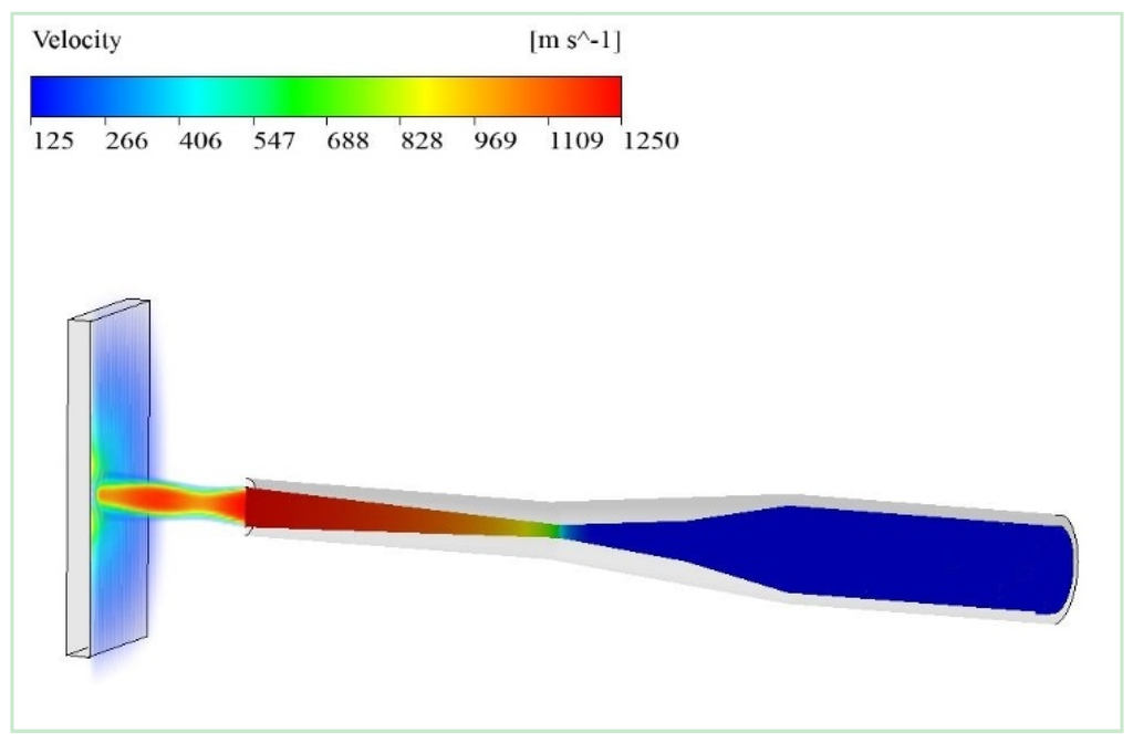
Figure 9.
Simulation of gas velocity for cold spray supersonic jet at 800 °C and 3 MPa estimated holistically from nozzle stagnation zone to the substrate surface, predicted by 3D multicomponent model.
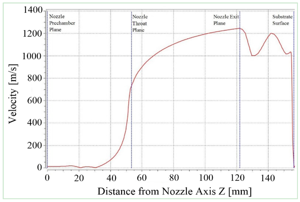
Figure 10.
Computed velocity profile with respect to nozzle axis for cold spray supersonic jet at 800 °C and 3 MPa.
Figure 11, shows the simulation of turbulence kinetic energy of carrier gas on the substrate surface predicted by the 3D multicomponent model. A rapid increase in nitrogen turbulence kinetic energy was observed near the surface of substrate which is at a 35 mm stand-off distance away from the nozzle exit. The multicomponent model quantified this turbulence kinetic energy for nitrogen as 11 m2/s2 at nozzle exit and 18000 m2/s2 near the surface of substrate. This prediction of turbulence kinetic energy would help to understand the presence and exact location of bow shock wave on the surface of substrate. For instance in Figure 11, an optimized 35 mm stand-off distance allows high turbulence to occur away from the nozzle exit. This optimization as predicted by the model would be helpful to improve the deposition process for which the turbulence kinetic energy is crucial. A low turbulence zone below 10 m2/s2 can be recognized in the surrounding air domain.
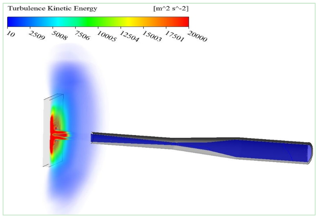
Figure 11.
Simulation of gas turbulent kinetic energy for cold spray supersonic jet at 800 °C and 3 MPa estimated holistically from nozzle stagnation zone to the substrate surface, predicted by 3D multicomponent model.
The holistic three dimensional multicomponent model simulations have provided a cost-effective insight of the cold gas dynamic spray process which would have been difficult through experimentation. The multicomponent model would be useful for fundamental studies of gas turbulence, heat transfer, temperature, pressure and velocity of supersonic gas at different locations throughout the process. A more valuable application of the developed multicomponent model could be the prediction of state of the particle just before the impact. With an existing outcome, it is clear that the multicomponent model can be extended for different cold spray nozzle geometries; variable stand-off distances and different cold spray initial conditions. It is worthwhile to mention here that after calibration and validation of the multicomponent model, the three dimensional model predictions are more accurate and reliable as compared to one dimensional model. It is believed that the multicomponent model is a more realistic model and it is aimed to cater for broader cold spray industry to solve complex scenarios occurring during the cold spray deposition process. The multicomponent model is capable to predict the history of cold spray gas and particle holistically from the stagnation zone to the deposition zone. Further investigations would be needed to examine this advanced three dimensional multicomponent model and to improve its performance to benefit coating and additive manufacturing industry with novel developments.
6. Conclusions
A three dimensional cold spray multicomponent model was developed to estimate the state of cold spray supersonic gas and system components holistically i.e., from the stagnation zone, at convergent section, at nozzle throat, at nozzle exit and onto the surface of substrate. The two equation k-ε model was utilized to develop the three dimensional numerical model. The developed model was calibrated and validated with temperature parameter measured experimentally for titanium substrate. The 3D model outcome for substrate temperature was in agreement with calibration and validation data. The multicomponent model can be identified as a realistic model for cold spray process revealing information about complex thermos-mechanical events with respect to cold spray gas temperature, velocity and turbulence kinetic energy from gas inlet to the lactation, at which the supersonic jet impinges onto the substrate. The 3D model estimation can be utilized to study the state of a cold spray particle just before the impact and residual stress developed after the deposition process.
Acknowledgments
Commonwealth Science and Industrial Research Organization (CSIRO), Clayton, Victoria, provided the Cold Spray facility for experimental testing.
Author Contributions
Muhammad Faizan Ur Rab carried out the multicomponent model development, Saden Zahiri conceived and performed the experiments; Saden Zahiri, Syed H. Masood, Mahnaz Jahedi, and Romesh Nagarajah supervised the research program; Muhammad Faizan Ur Rab wrote the initial draft; all other authors reviewed and contributed to revisions of the work in the final form.
Conflicts of Interest
The authors declare no conflict of interest.
Nomenclature
| c | m/s | Local speed of sound in fluid |
| cp | m2/s2·K | Specific Heat Capacity at Constant Pressure |
| Cμ | 0.09 | k-ε Turbulence Model Constant |
| Cε1 | Dimensionless | k-ε Turbulence Model Constant |
| Cε2 | Dimensionless | k-ε Turbulence Model Constant |
| CClip | Dimensionless | Clip factor coefficient for turbulence energy |
| CScale | Dimensionless | Scaling coefficient for curvature correction |
| g | m/s2 | Gravity vector |
| h | m2/s2 | Specific static (thermodynamic) enthalpy |
| htot | m2/s2 | Specific total enthalpy |
| k | m2/s2 | Turbulent Kinetic Energy per Unit Mass |
| M | Dimensionless | Local Mach number |
| p' | kg/m·s2 | Modified pressure |
| p | kg/m·s2 | Static (thermodynamic) pressure |
| Pk | kg/m·s3 | Turbulence energy |
| pref | kg/m·s2 | Reference pressure |
| Prt | Dimensionless | Turbulent Prandtl Number, cp μt/λt |
| ptot | kg/m·s2 | Total pressure |
| R0 | m3·Pa/K·mol | Universal gas constant = 8.3145 m3·Pa/K·mol |
| Re | Dimensionless | Reynolds number, r U d/m |
| Sct | Dimensionless | Turbulent Schmidt Number |
| t | s | Time |
| Tdom | K | Domain temperature |
| Tstat | K | Static (thermodynamic) temperature |
| Ttot | K | Total temperature |
| U | m/s | Velocity magnitude |
| u | m/s | Fluctuating velocity component |
| ε | m2/s3 | Turbulent (Eddy) Dissipation Rate |
| λ | kg/m·s3·K | Thermal Conductivity |
| μ | kg/m·s | Molecular (Dynamic) Viscosity |
| μeff | kg/m·s | Effective viscosity |
| μt | kg/m·s | Turbulent (Eddy) Viscosity |
| ρ | kg/m3 | Density |
| Гt | kg/m·s | Turbulent diffusivity |
Appendix
Governing Flow Equations
The principle continuity equation is expressed as:
where ρ is the density of the fluid, Uj is the velocity vector of the fluid and t is time.
The relative mass flux accounts for differential motion of the individual components. It is possible to model this term in a manner to include concentration gradients, a pressure gradient, external forces or a temperature gradient. For multicomponent flow, the effect of concentration gradient is of great interest. Considering this effect in a model gives rise to diffusion-like quantities and relative mass flux can be expressed as:
where Гi is a molecular diffusion coefficient accommodating kinematic diffusivity of multicomponent flow.
The modified pressure p' can be defined as:
The effective viscosity μeff can be expressed as:
where μt is the turbulence viscosity and μ is the molecular (dynamic) viscosity.
The static enthalpy hstat is a measure of the energy contained in a fluid per unit mass having the relationship:
where cp(T) is specific heat at constant pressure. The default reference state is Tref = 0 K and href = 0 J/Kg.
References
- Zahiri, S.H.; Phan, T.D.; Masood, S.H.; Jahedi, M. Development of holistic three-dimensional models for cold spray supersonic jet. J. Therm. Spray Technol. 2014, 23, 919–933. [Google Scholar] [CrossRef]
- Papyrin, A.; Kosarev, V.; Klinkov, S.; Alkhimov, A.; Fomin, V.M. Cold Spray Technology, 1st ed.; Elsevier: Oxford, UK, 2007; pp. 14–20. [Google Scholar]
- Pawlowski, L. The Science and Engineering of Thermal Spray Coatings, 2nd ed.; Willey: Chichester, UK, 2008; pp. 96–99. [Google Scholar]
- Li, S.; Muddle, B.; Jahedi, M.; Soria, J. A numerical investigation of the cold spray process using under-expanded and over-expanded jets. J. Therm. Spray Technol. 2012, 21, 108–120. [Google Scholar] [CrossRef]
- Stoltenhoff, T.; Kreye, H.; Richter, H.J. An analysis of the cold spray process and its coatings. J. Therm. Spray Technol. 2002, 11, 552–550. [Google Scholar] [CrossRef]
- Karimi, M.; Fartaj, A.; Rankin, G.; Vanderzwet, D.; Birtch, W.; Villafuerte, J. Numerical simulation of the cold gas dynamic spray process. J. Therm. Spray Technol. 2006, 15, 518–523. [Google Scholar] [CrossRef]
- Ning, X.; Wang, Q.S.; Ma, Z.; Kim, H. Numerical study of in-flight particle parameters in low-pressure cold spray process. J. Therm. Spray Technol. 2010, 19, 1211–1217. [Google Scholar] [CrossRef]
- Yin, S.; Wang, X.; Xu, B.; Li, W. Examination on the calculation method for modeling the multi-particle impact process in cold spraying. J. Therm. Spray Technol. 2010, 19, 1032–1041. [Google Scholar] [CrossRef]
- Samareh, B.; Stier, O.; Luthen, V.; Dolatabadi, A. Assessment of CFD modeling via flow visualization in cold spray process. J. Therm. Spray Technol. 2009, 18, 934–943. [Google Scholar] [CrossRef]
- Zuckerman, N.; Lior, N. Jet impingement heat transfer: Physics, correlations and numerical modeling. Adv. Heat Transf. 2006, 39, 565–631. [Google Scholar]
- Alam, M.; Naser, J.; Brooks, G. Computational fluid dynamics simulation of supersonic oxygen jet behavior at steelmaking temperature. Metall. Mater. Trans. B 2010, 41, 636–645. [Google Scholar] [CrossRef]
- Solver Theory Guide; release 14.5; ANSYS, Inc.: Pittsburgh, PA, USA, 2012.
- Menter, F.R. Eddy viscosity transport equations and their relation to the k-ε model. J. Fluids Eng. 1997, 119, 876–884. [Google Scholar] [CrossRef]
- Schlichting, H. Boundary Layer Theory; McGraw-Hill: New York, NY, USA, 1979. [Google Scholar]
- Wilcox, D.C. Turbulence Modelling for CFD, 3rd ed.; DCW Industries: La Canada Flintridge, CA, USA, 2000. [Google Scholar]
- Kumar, A.; Ghosh, S.; Dhindaw, B.K. Simulation of cooling of liquid Al–33 wt % Cu droplet impinging on a metallic substrate and its experimental validation. Acta Mater. 2009, 58, 122–133. [Google Scholar] [CrossRef]
- Benyahiaa, S.; Syamlala, M.; O’Brien, T.J. Evaluation of boundary conditions used to model dilute, turbulent gas/solids flows in a pipe. Powder Technol. 2005, 156, 62–72. [Google Scholar] [CrossRef]
- Novoselova, T.; Fox, P.; Morgan, R.; O’Neil, W. Experimental study of titanium/aluminum deposits produced by cold gas dynamic spray. Surf. Coat. Technol. 2004, 200, 2775–2783. [Google Scholar] [CrossRef]
- Boyer, R.; Welsch, G.; Collings, E.W. Materials Properties Handbook: Titanium Alloys, 3rd ed.; ASM Int.: Novelty, OH, USA, 2003. [Google Scholar]
- Franz, G.; Abed-Meraim, F.; Lorrain, J.P.; Zineb, T.B.; Lemoine, X.; Berveiller, M. Ellipticity loss analysis for tangent moduli deduced from a large strain elastic–Plastic self-consistent model. Int. J. Plast. 2009, 25, 205–238. [Google Scholar] [CrossRef]
- Li, W.-Y.; Yin, S.; Guo, X.; Liao, H.; Wang, X.F.; Coddet, C. An investigation on temperature distribution within the substrate and nozzle wall in cold spraying by numerical and experimental methods. J. Therm. Spray Technol. 2012, 21, 41–48. [Google Scholar] [CrossRef]
- Ryabinin, A.; Irissou, E.; McDonald, A.; Legoux, J.-G. Simulation of gas-substrate heat exchange during cold-gas dynamic spraying. Int. J. Therm. Sci. 2012, 56, 12–18. [Google Scholar] [CrossRef]
- Inman, J.A.; Danehy, P.M.; Bathel, B.; Alderfer, D.W.; Nowak, R.J. Laser-induced fluorescence velocity measurements in supersonic underexpanded impinging jets. In Proceedings of the 48th AIAA Aerospace Science Meeting Including the New Horizons forum and Aerospace Exposition, Orlando, FL, USA, 4–7 January 2010.
- Li, C.-J.; Li, W.-Y.; Liao, H. Examination of the critical velocity for deposition of particles in cold spraying. J. Therm. Spray Technol. 2006, 15, 212–222. [Google Scholar] [CrossRef]
© 2015 by the authors; licensee MDPI, Basel, Switzerland. This article is an open access article distributed under the terms and conditions of the Creative Commons Attribution license (http://creativecommons.org/licenses/by/4.0/).