1. Introduction
Over the past decades numerous publications have reported on the outstanding properties of carbon nanotubes (CNT), e.g., high electrical and thermal conductivity, high tensile strength, and high e-modulus, rendering them as suitable for a wide range of applications in electronic, optical, mechanical, sensor or electrochemical storage devices [
1,
2,
3,
4,
5]. Using chemical vapor deposition (CVD), nanotubes can be synthesized as ordered arrays of vertically aligned carbon nanotubes (VACNT) on a relatively large area [
6,
7,
8]. Especially, the height of a VACNT forest is a crucial structural factor and determines performance in many applications. Therefore, methods for height determination in a fast and minimally-destructive way have to be established.
The common technique for VACNT height characterization is scanning electron microscopy (SEM) [
3,
9,
10]. Although it can be used not only for height characterization but also for alignment detection, it suffers from several major drawbacks [
10]. Besides the expensive measurement and vacuum equipment, the specimen size and measurement throughput is limited by the size of the sample chamber. Furthermore, the height can only be determined directly at the edge of the VACNT to the substrate. Consequently, the measured sample region can be subject to serious damage during the preparation process, influencing the CNT height and/or degree of alignment [
10]. Moreover, only along the cut, precise height information is obtained and height homogeneity is difficult to assess.
Further concepts of VACNT height characterization are
in situ methods such as laser displacement [
11], time-resolved reflectivity [
12], single-slit laser diffractography [
13] and optical interference [
14], and optical absorption [
15]. These non-destructive techniques provide an excellent insight into the growth kinetics and a control on the VACNT forest height. Using laser displacement, even very high VACNT forests can be analyzed, while the other methods are limited to short heights due to the strong light absorption by VACNT [
11]. However, all of these
in situ methods suffer from the disadvantage that specialized CVD oven constructions are required, which possibly influence the growth process [
16].
In the following, confocal microscopy is presented for the ex situ characterization of VACNT forest heights on various substrates. This optical imaging technique combines a fast and minimally-destructive characterization with high vertical resolution. For the first time, VACNT forest height is measured by means of visible light microscopy. Typically this is hindered by the strong absorption properties of VACNT. The throughput of measurements is increased by a factor of 3–4 by using confocal microscopy compared to SEM height determination. The output is a 3D topography image in almost the same range of resolution as observable by SEM.
2. Experimental Section
The basic principle of confocal microscopy was patented by Marvin Minsky in 1957 [
17,
18]. A scheme of a nowadays typically-used optical set is shown in (
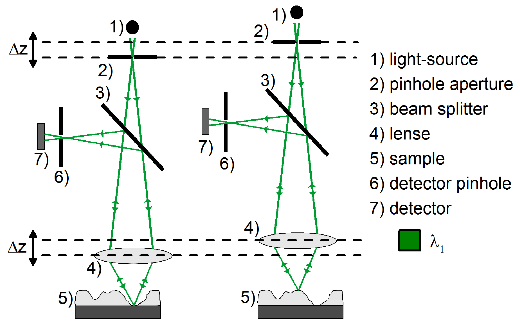
Figure 1). As it can be seen, monochromatic light is guided through a pinhole aperture, passes through a focusing lens and a semi-transparent mirror before it incidents on the substrates surface. There, it is reflected both diffusely or directly backwards through the semi-transparent mirror and guided to another pinhole in front of the detector. Only the specular reflected light has the same focal length as the incident light and, thus, the surface point on the substrate is mapped on the detector. During a confocal microscopy measurement, either the sample or the optical head is moved successively in the
z-direction to change the focal path length for imaging each point of a 3D element on the surface. All images are detected stack-wise and subsequently assembled to a 3D topography image using computational software.
Figure 1.
Schematic principle of confocal microscopy for topography-mapping for VACNT forest height characterization. While, on the left side, only the light from substrate surface is reflected directly, on the right side the light is reflected directly from the top of VACNT.
Figure 1.
Schematic principle of confocal microscopy for topography-mapping for VACNT forest height characterization. While, on the left side, only the light from substrate surface is reflected directly, on the right side the light is reflected directly from the top of VACNT.
For the experiments presented in this report, an objective (HCX PL Fluostar) with twenty-fold magnification on a Leica DCM 3D system (Leica Microsystems GmbH, Wetzlar, Germany), with a maximal lateral resolution of 0.28 µm and a maximal resolution of 15 nm in the z-direction, is applied for confocal microscopy measurements. This system uses a micro-mirror array as an array of pinholes for detecting a 2D area in each stack. Therefore, it is not necessary to guide the incident light point by point over the surface and an area of maximal 636.6 µm × 477.3 µm can be measured at once for this resolution. Furthermore, the optical head is moved by using a multiphase motor for scanning the surface topography in the z-direction with a maximal range of 1.1 mm. The wavelength of the used LED is 460 nm. For the assembly of the detected images, the software Leica Map 6.2 is used.
In this report we demonstrate the suitability of confocal microscopy as a fast and simple method for investigating the VACNT growth by means of atmospheric pressure CVD (AP-CVD) and as a general tool for process control. Nickel, stainless steel, p-doped silicon (100), and Corning C1737 glass substrates are used as substrates for AP-CVD. Each substrate is coated with an Al
2O
3 buffer layer and a Fe
xCo
yO
z catalyst layer by a dip coating procedure, described elsewhere [
19]. The resulting metal oxide film thicknesses are 35–40 nm Fe
xCo
yO
z on 20 nm Al
2O
3 and 50 nm Al
2O
3, respectively.
The growth process of VACNT is carried out in a three-zone batch furnace reactor by CVD from ethene precursor gas at 750 °C and 20 min process duration using the super-growth process, as introduced by Hata
et al. [
6] (Details in
Supporting Information). For VACNT forest height determinations small parts of the VACNT are moved from the substrate surface as reference. All confocal microscopy measurements are carried out in ambient conditions and with twenty-fold magnification. This results in a vertical resolution of 15 nm with a vertical measurement range up to 1 mm.
Simultaneous mapping of the VACNT and substrate surface allows measuring the VACNT forest height by comparing the substrate level and VACNT top level. Additionally, some adjustments are found to be crucial to get high-quality image recording over the whole area of substrate and VACNT:
The light intensity is set to two levels: low (1%–15%) for the substrate area and high (50%–100%) for the VACNT area. The reason is the low reflection
R (specular plus diffusive) of the VACNT of less than 1%. In contrast, the used substrates have a reflection
R between 15%–35%. (see
Supplementary Materials)
The transition of the light intensity level from low to high is set in the vertical middle of VACNT forest.
The vertical scan range is adjusted to the VACNT forest height for a time-saving measurement.
To follow these adjustments, a bottom-up-scan from substrate to VACNT forest with a change of light intensity level almost in the middle of the nanotube forest is carried out. At a vertical scan step size of 1 μm, the time for one measurement is approximately 2–4 min, depending on the vertical measurement range, resulting in a 3D topography image of ~500 × 500 µm2 in size.
3. Results and Discussion
The suitability of confocal microscopy as an alternative method to SEM for VACNT forest height estimation was studied by comparing images of the same sample area taken with both methods (
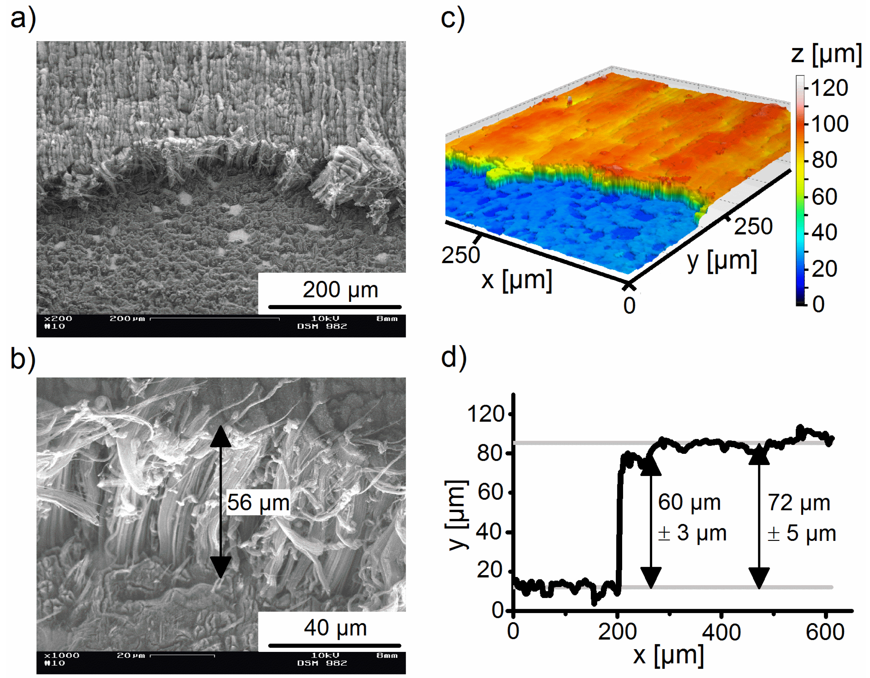
Figure 2). Due to specific measurement adjustments, this optical imaging technique can be applied for the first time for height characterization of highly-absorbing VACNT forests. For determining the VACNT forest height, a vertical profile is extracted from the topography image.
Figure 2.
SEM images of a VACNT sample on nickel foil with Al2O3 buffer layer (20 nm) and FexCoyOz catalyst layer (40 nm) with lower (a) and higher (b) magnification. For SEM-based height determination a correction factor of has
to be applied, due to specimen tilting. Confocal microscopy topography image of the same sample (c) and vertical profile extracted from confocal microscopy image (d).
One of the advantages of confocal microscopy compared to SEM can be clearly seen. While, with SEM, a CNT height can only be measured at the edge to the substrate, confocal microscopy also gives height information from the area beyond the edge. A VACNT height of 56 µm is determined with SEM at the edge, being in the same range of the value measured with confocal microscopy. However, confocal microscopy allows a differentiation between the height directly at the edge (60 µm) and an average value in the area beyond the edge (72 µm). This is of importance since preparation failures especially occur in the edge regions. The second advantage of confocal microscopy, compared to SEM, is the possibility to extract a height profile, being very useful for inhomogeneity analysis of VACNT heights and also for estimating substrate roughness. By measuring the roughness values
Ra the error in height determination is calculated (details in
supplementary materials). Furthermore, the substrate morphology shows an effect on VACNT structure. In SEM images of non-transferred VACNT forests, a lamellar orientation can be seen, especially if VACNT are lower than 100 µm. This is probably due to the morphology of the used nickel foil substrates, which show a similar structure (details in
supplementary materials).
Although VACNT have a high absorption in the visible wavelength range, the light intensity reflected to the detector (
R = 0.64%) is high enough to detect a significant number of pixels (at least 80%). This is due to the structure of VACNT in the forest. While being well ordered in the middle vertical sector of the forest, the CNT become misaligned at the top [
20]. The horizontal orientation of some CNT defines a graphitic behavior, resulting in a slight light reflection [
21,
22].
The importance of horizontally-oriented CNT in the top region of the forest becomes obvious for confocal microscopy investigation when applied to samples being transferred to a secondary substrate. A film transfer is applied when the VACNT are required on alternative substrates not being suitable for CVD processing because of limited thermal stability (details in
supplementary materials). Here, the as-grown VACNT on the initial substrate is transferred by hot calendering to an aluminum foil, coated with a 1 μm thick primer layer. A semi-continuous sheet to roll transfer is performed with a custom-made hot calender at 100 °C and different pressing forces of the rolls. The best results of homogeneity in VACNT transfer is observed by a roll pressing force of 300 N (
Figure 3). The main principle of this film transfer of VACNT to primer-coated aluminum foil was described by Brückner
et al. using a static process [
23].
Figure 3.
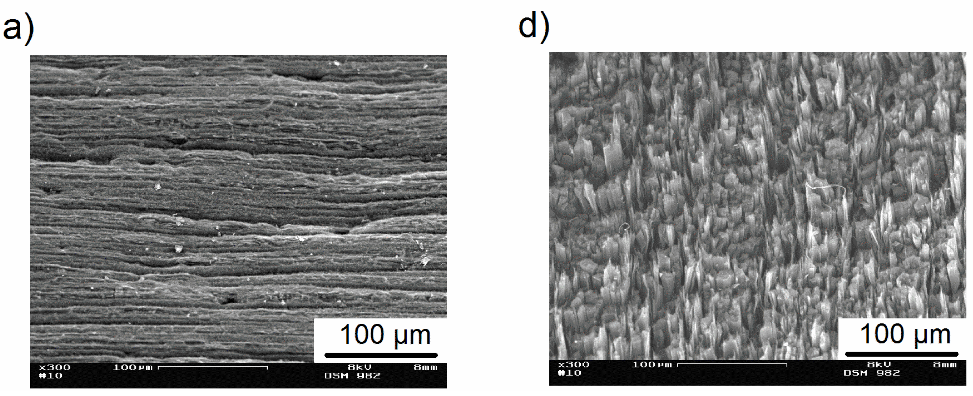
SEM image of VACNT surface with lower and higher magnification (a,b) before and (d,e) after film transfer and confocal microscopy image of VACNT on nickel foil before (c), and on primer-coated aluminum foil (f) after film transfer.
Figure 3.
SEM image of VACNT surface with lower and higher magnification (a,b) before and (d,e) after film transfer and confocal microscopy image of VACNT on nickel foil before (c), and on primer-coated aluminum foil (f) after film transfer.
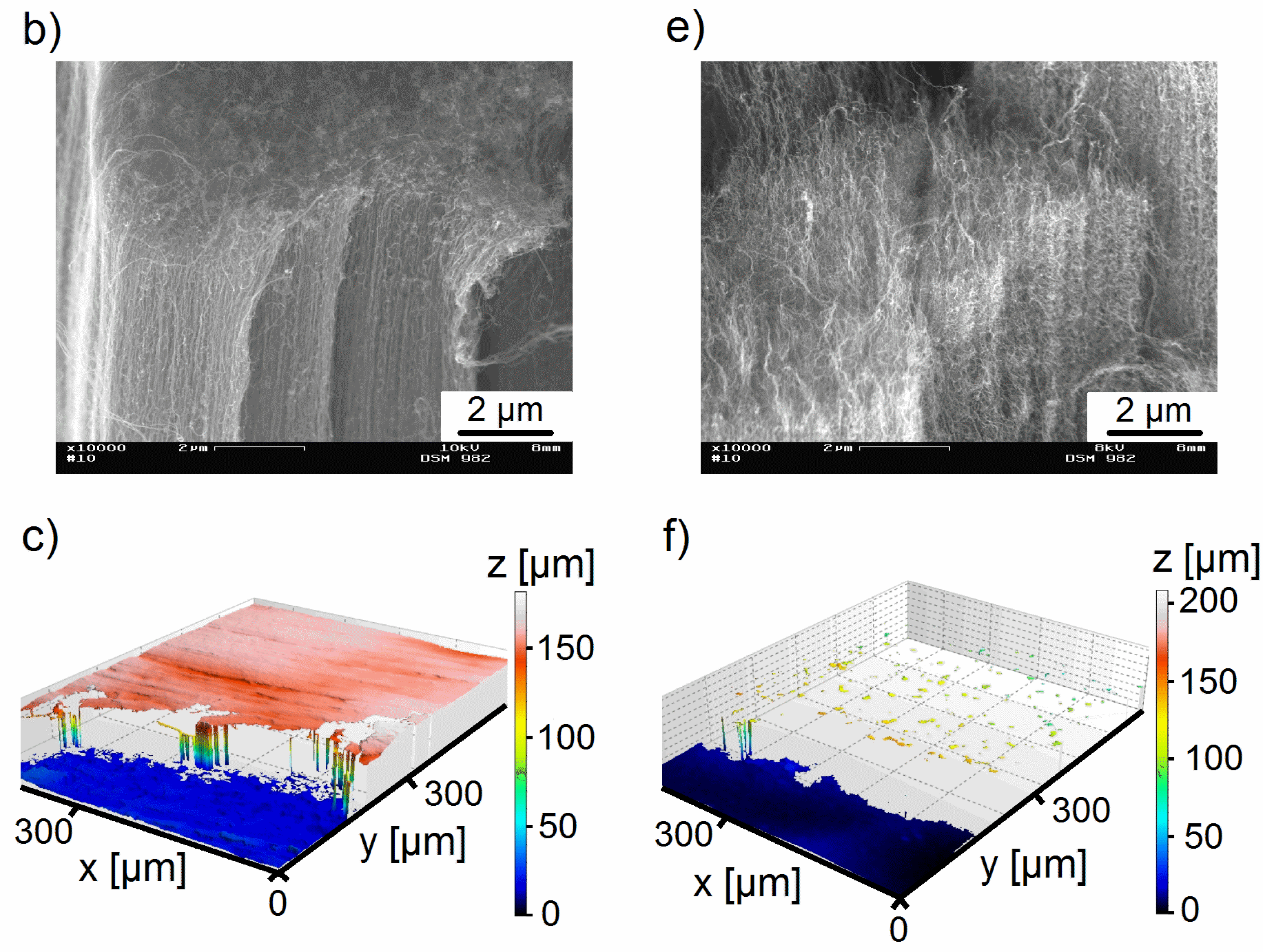
While, with lower pressing forces, large areas of non-transferred VACNT are obtained, higher values of applied pressing force cause a deformation of VACNT and transfer of platelets of the Al
2O
3 buffer layer (
Figure 4). If VACNT are transferred by optimum roll pressure without Al
2O
3, a black carpet is observed on the primer-coated aluminum foil. This corresponds to a reflection
R of 0.46%.The surface of VACNT becomes brighter if grains of the Al
2O
3 buffer layer are transferred as a consequence of increased light reflection (
R = 3.9%). This results in a good imaging with confocal microscopy (
Figure 4b). In contrast to this, optimum transfer without Al
2O
3 leads to a high amount of non-detectable points (
Figure 3f). This is due to the high perfection of vertical alignment of VACNT at the top of the film (former base). Therefore confocal microscopy provides an indirect technique for process control of the substrate transfer by hot calendaring.
Comparing the SEM images of the initial VACNT on nickel foil (
Figure 3a,b) and the homogeneously transferred VACNT on primer-coated aluminum (
Figure 3d,e), the different surface structures of the forests become obvious. As already discussed above, after CVD a flat plane with misaligned CNTs is found at the top. On the other hand, after the film transfer, bundles of VACNT with good vertical alignment at the top of the forest are observed. The confocal microscopy images of VACNT on nickel foil before transfer show only a few non-measured points (~10%). From the confocal microscopy image of the VACNT after film transfer to primer-coated aluminum foil, almost no significant information of the VACNT height can be extracted because of a high number of points below the detection limit. This is a result of low light reflection at the surface of the transferred sample. For these kind of samples the method could not yet be successfully applied.
Figure 4.
Photograph of VACNT (dark black area) transferred to primer-coated aluminum foil (grey area) by hot calendar with too high a pressing force (400 N) (a). Confocal microscopy image of the transferred film (b). SEM images of transferred film with higher (c) and lower (d) magnification.
Figure 4.
Photograph of VACNT (dark black area) transferred to primer-coated aluminum foil (grey area) by hot calendar with too high a pressing force (400 N) (a). Confocal microscopy image of the transferred film (b). SEM images of transferred film with higher (c) and lower (d) magnification.
However, the confocal microscopy method is well suited for
ex situ process control and optimization. This can be illustrated by investigating the influence of the Al
2O
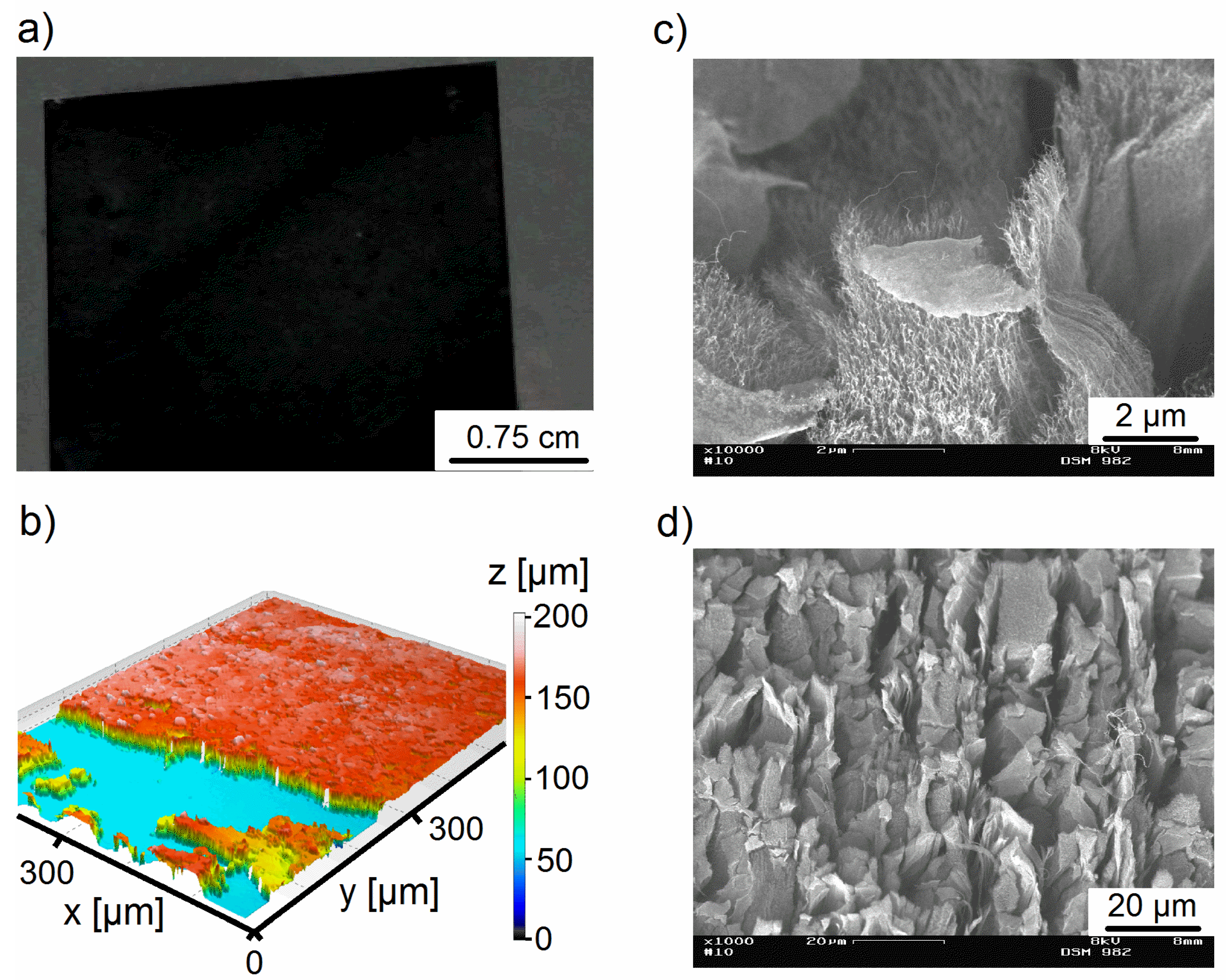
3 buffer layer thickness and the process duration on VACNT growth. By increasing the thickness of Al
2O
3 buffer layer from 20 nm to 54 nm, the resulting VACNT height increases from 70 μm to 130 μm (
Figure 5). This is probably due to an effect described by Burt
et al. [
24]. They found an influence of the buffer layer’s morphology on the density of catalyst nanoparticles and thereby the growth rate of CNT.
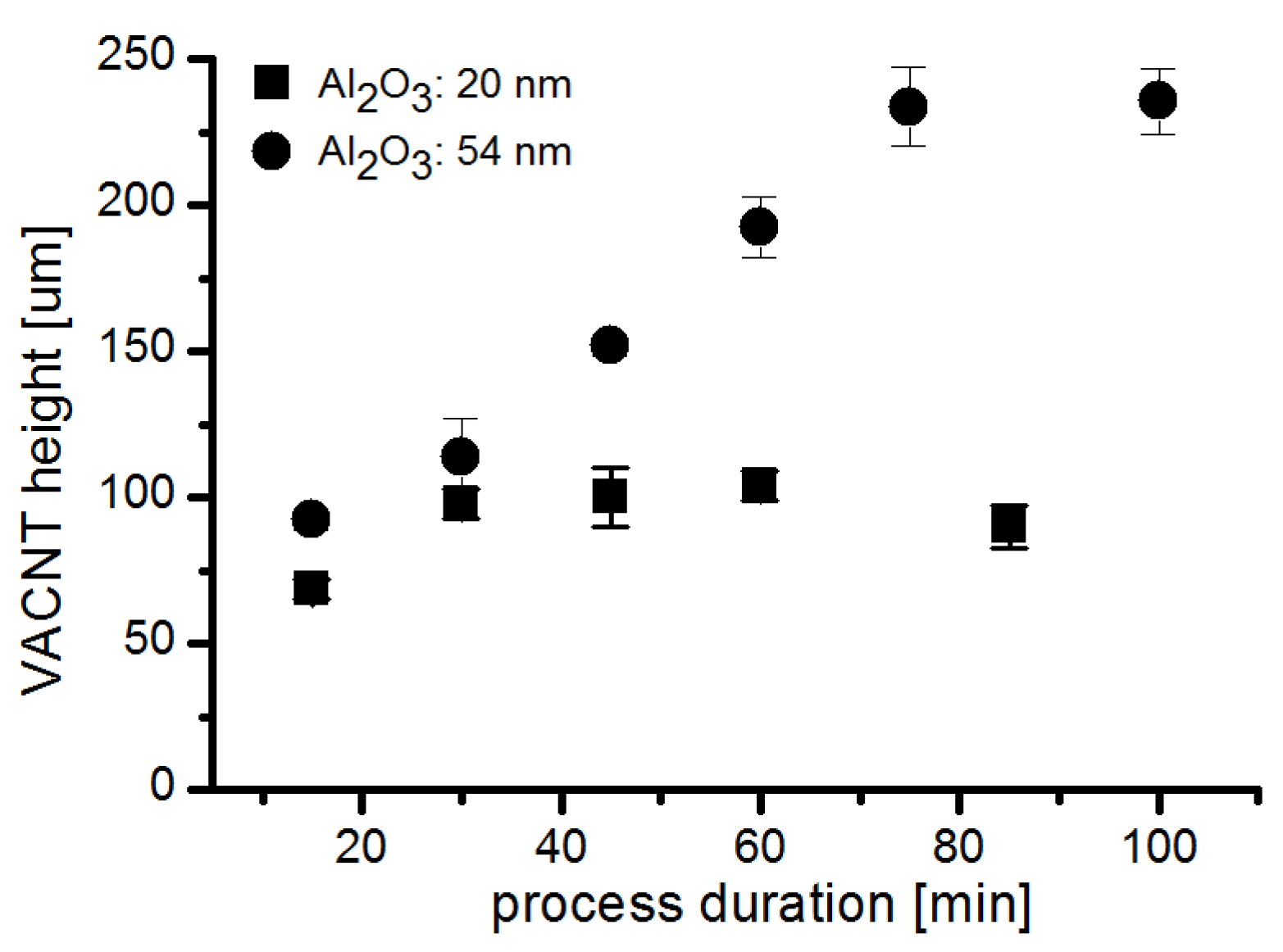
Using confocal microscopy rapid
ex situ evaluation of growth kinetics on catalyst layers with different buffer layer thicknesses is possible (
Figure 6). While, with 20 nm thick buffer layers, the growth terminates after 30 min, a 54 nm thick buffer layer results in termination after 75 min. A linear increase in VACNT height is observed in the latter case. The growth terminates at maximum VACNT height of 240 μm. This is a remarkably high value for wet-chemically coated buffer and catalyst layers on metal foil. The confocal microscopy technique allows a rapid characterization, as it is required for the determination of VACNT forest height variation at different locations of the substrate.
Figure 5.
SEM image, confocal microscopy image and profile of VACNT grown with Al2O3 buffer layer (54 nm), FexCoyOz catalyst layer [20 nm, process duration of 20 min (a–c), and 75 min (d–f)].
Figure 5.
SEM image, confocal microscopy image and profile of VACNT grown with Al2O3 buffer layer (54 nm), FexCoyOz catalyst layer [20 nm, process duration of 20 min (a–c), and 75 min (d–f)].
Figure 6.
Forest height of VACNT with increasing process duration grown by CVD from nickel foil substrates, wet-chemically coated with different thicknesses of Al2O3 buffer layer (■ Al2O3: 20 nm, ● Al2O3: 54 nm), and 40 nm FexCoyOz catalyst layer.
Figure 6.
Forest height of VACNT with increasing process duration grown by CVD from nickel foil substrates, wet-chemically coated with different thicknesses of Al2O3 buffer layer (■ Al2O3: 20 nm, ● Al2O3: 54 nm), and 40 nm FexCoyOz catalyst layer.

