
Correlation of Growth and Surface Properties of Poly(\(p\)-xylylenes) to Reaction Conditions


Abstract
:1. Introduction

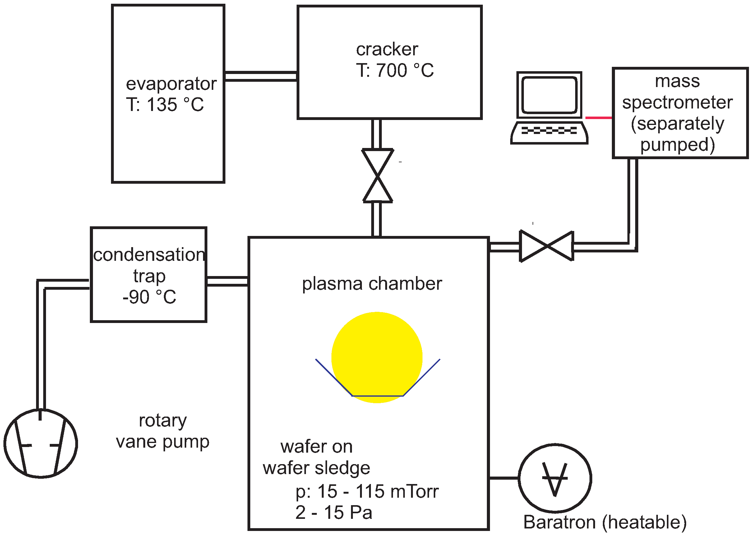
2. Experimental Section

3. Results and Discussion
3.1. Introduction
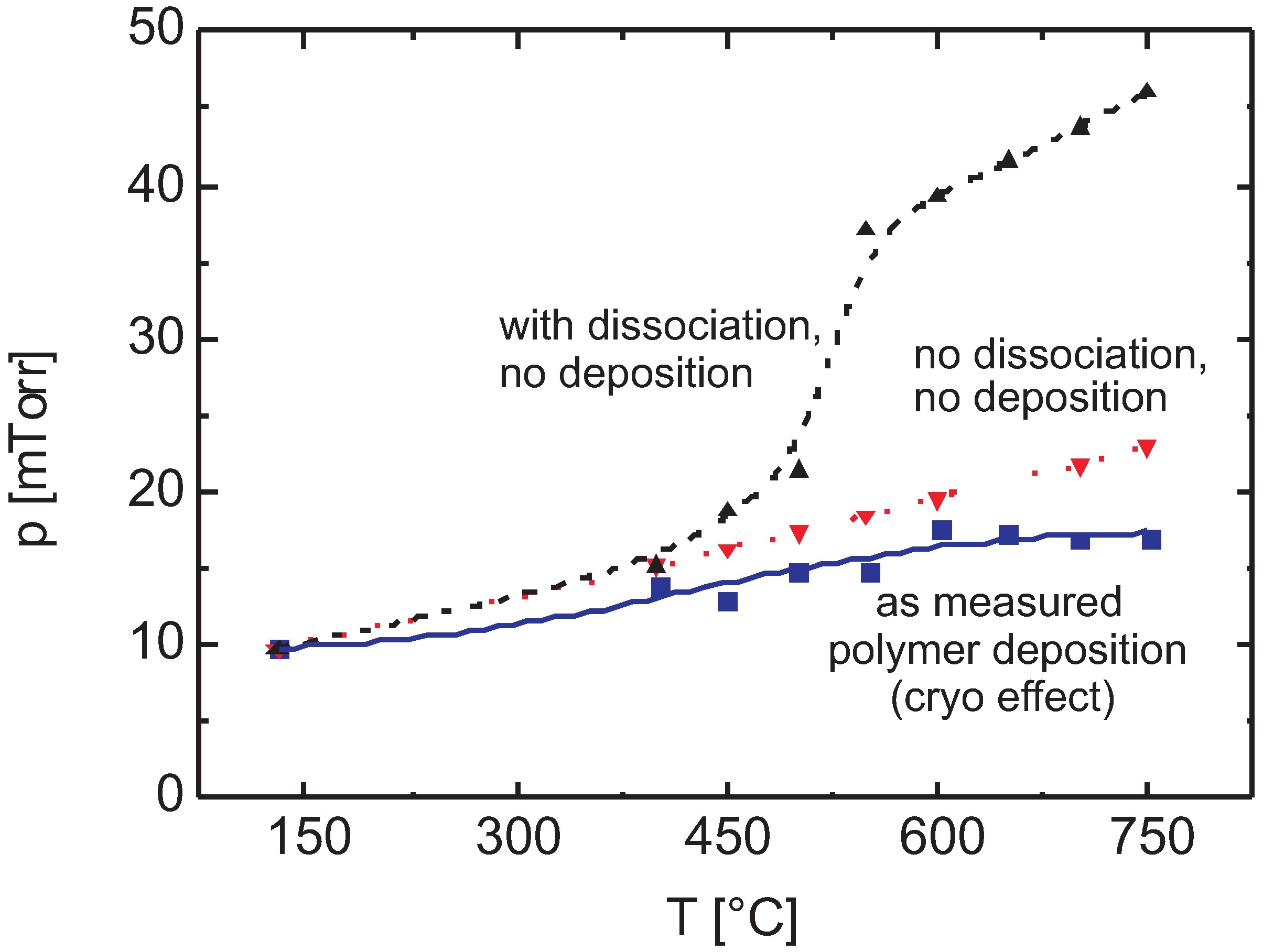
3.2. Dissociation
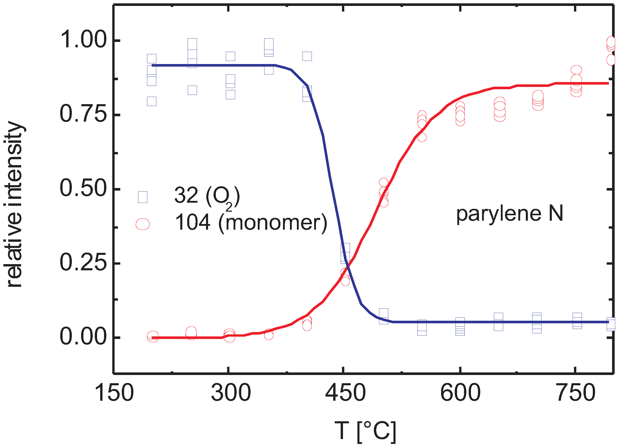
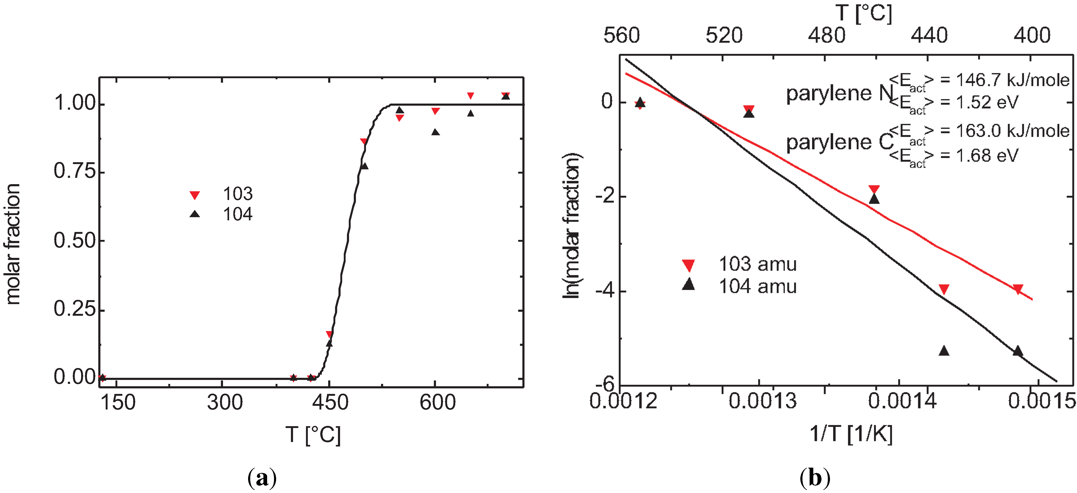
3.2.1. Thermal Activation

3.2.2. Plasma Activation
3.2.3. Discussion
Efficiency for Thermal Cleavage

- entering velocity ( 1000 K): 480 m/s, Å, 10 Pa (6.4 × 10 cm): 1.25 mm;
- entering velocity ( 1000 K): 480 m/s, Å, p = 40 Pa (25.6 × 10 cm): 0.8 mm.
Plasma Cleavage
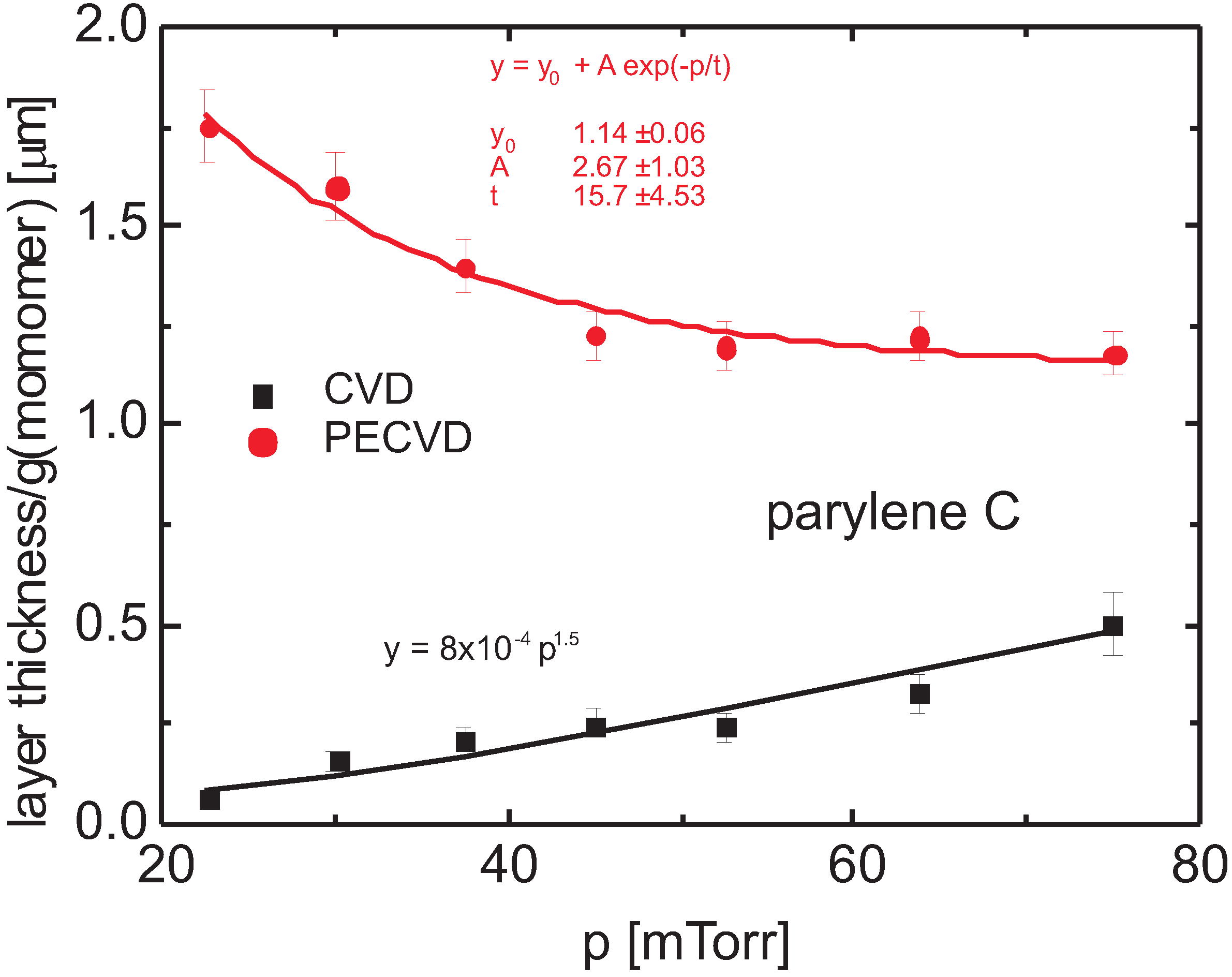
Surface Polymerization vs. Volume Polymerization
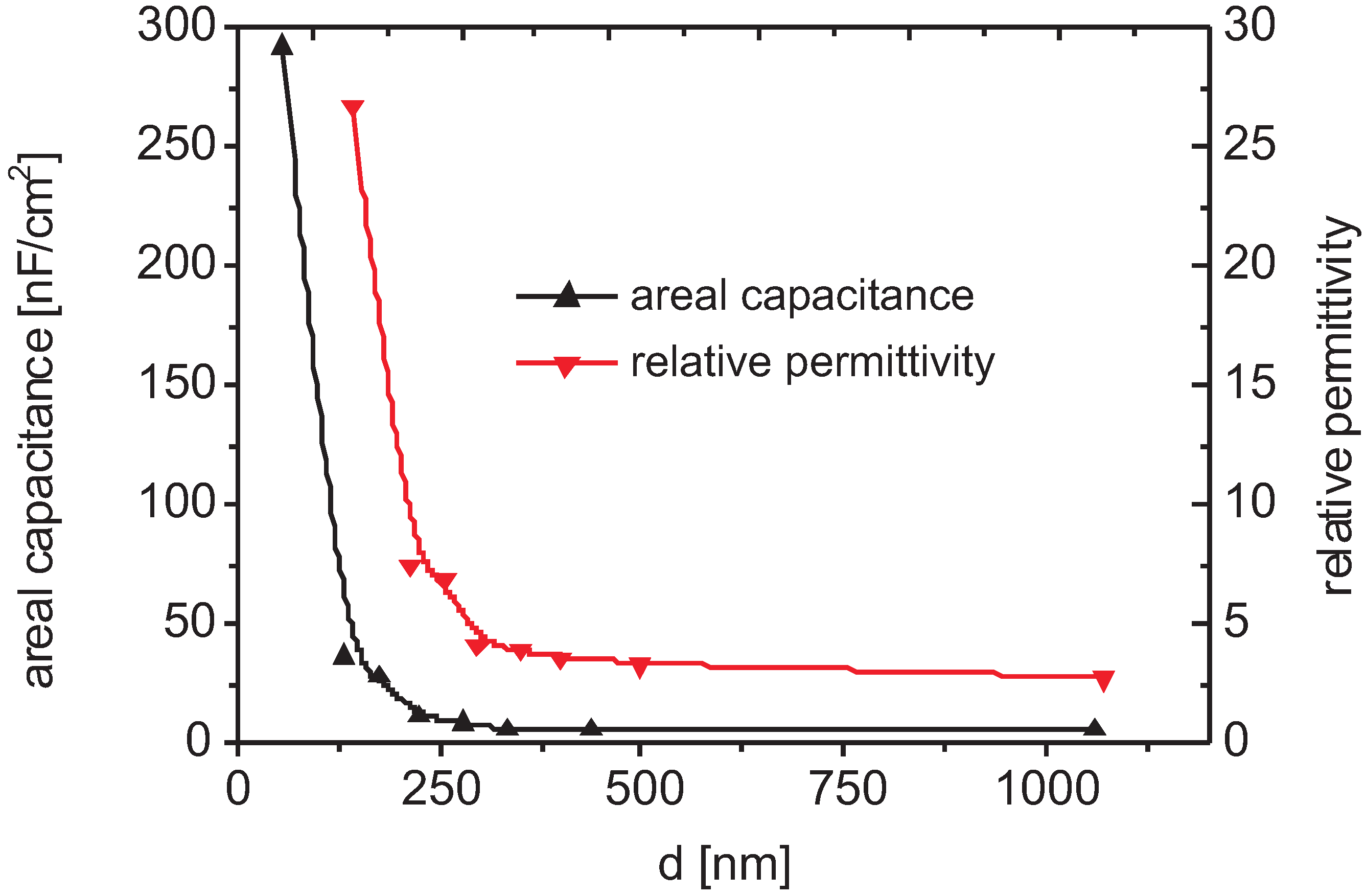
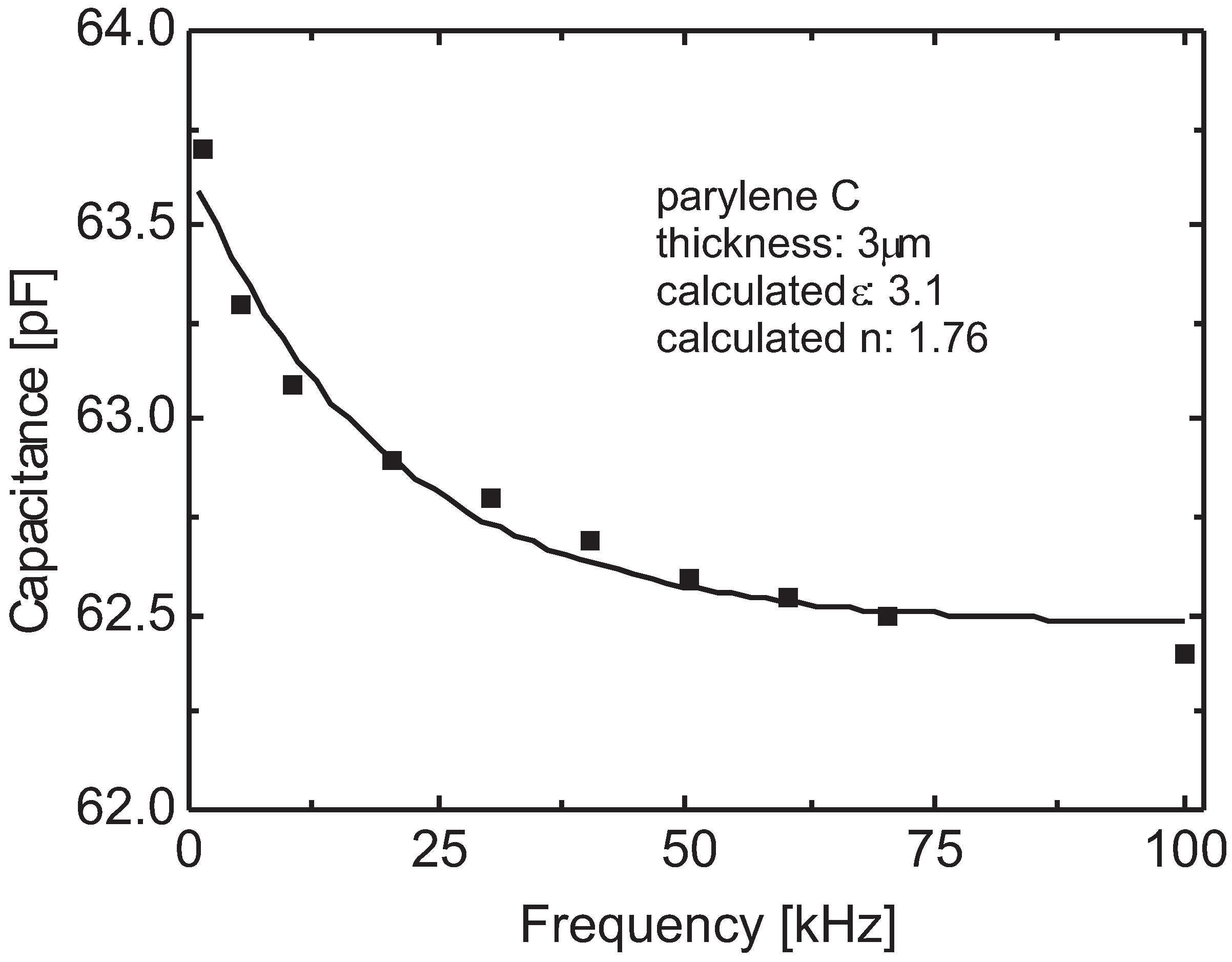
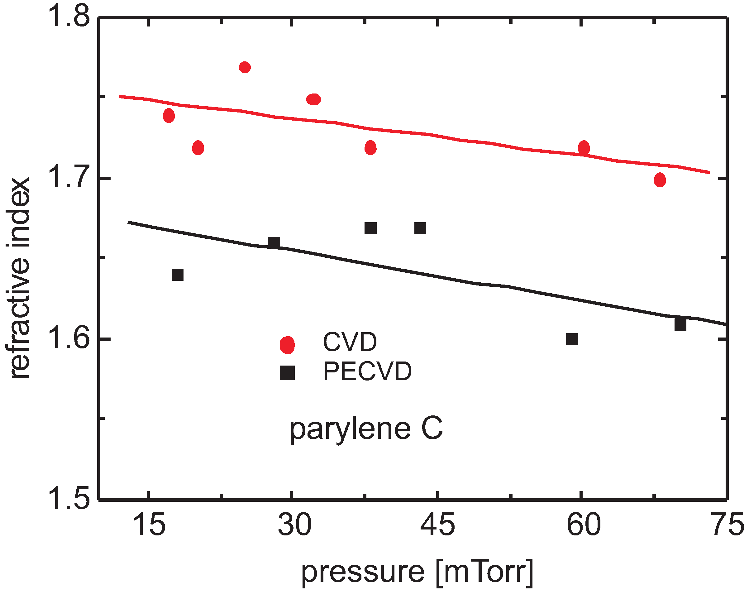
3.3. Bulk Properties

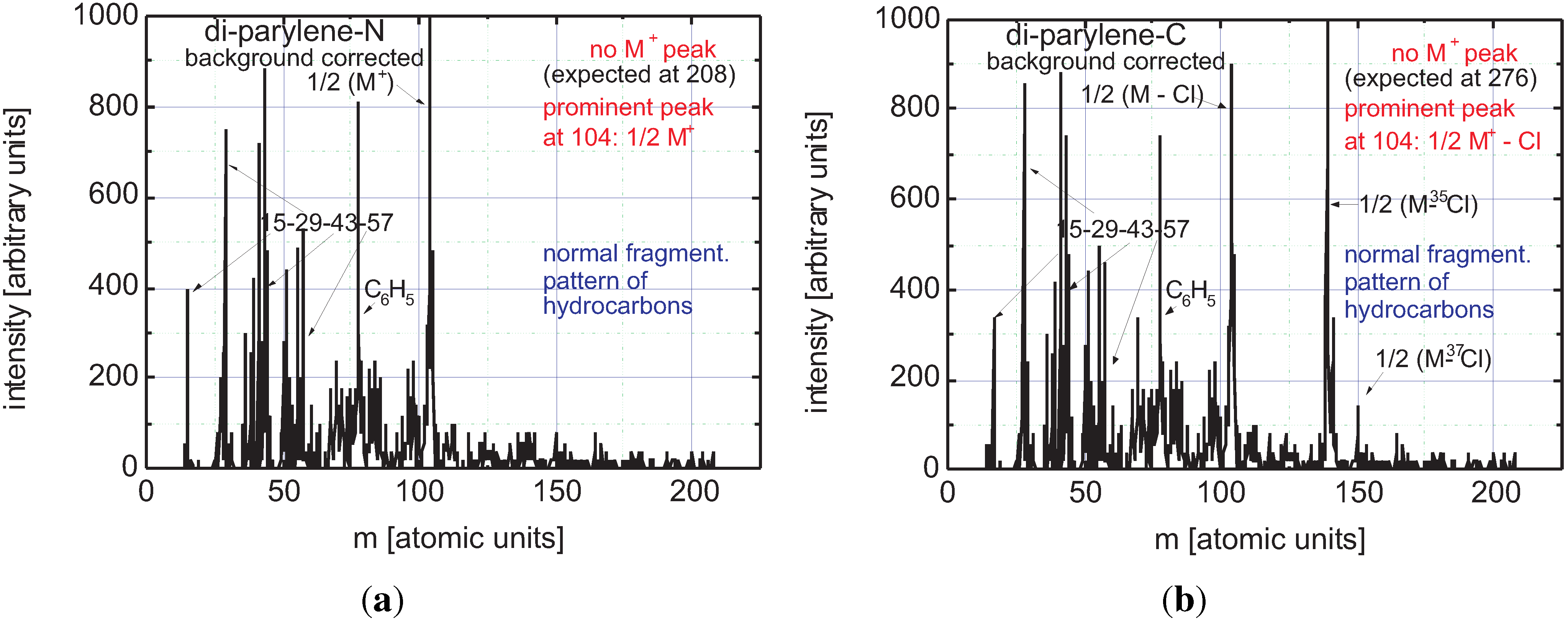
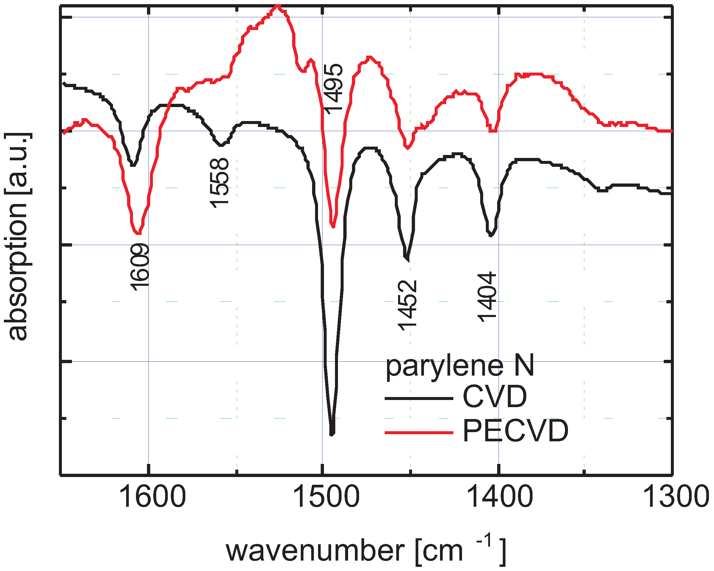
3.4. Spectral Identification
3.5. Surface Properties
- parylene N: CVD and pure PECVD;
- parylene C: CVD and thermally-assisted PECVD;
- parylene C: CVD, copolymerized with CF.
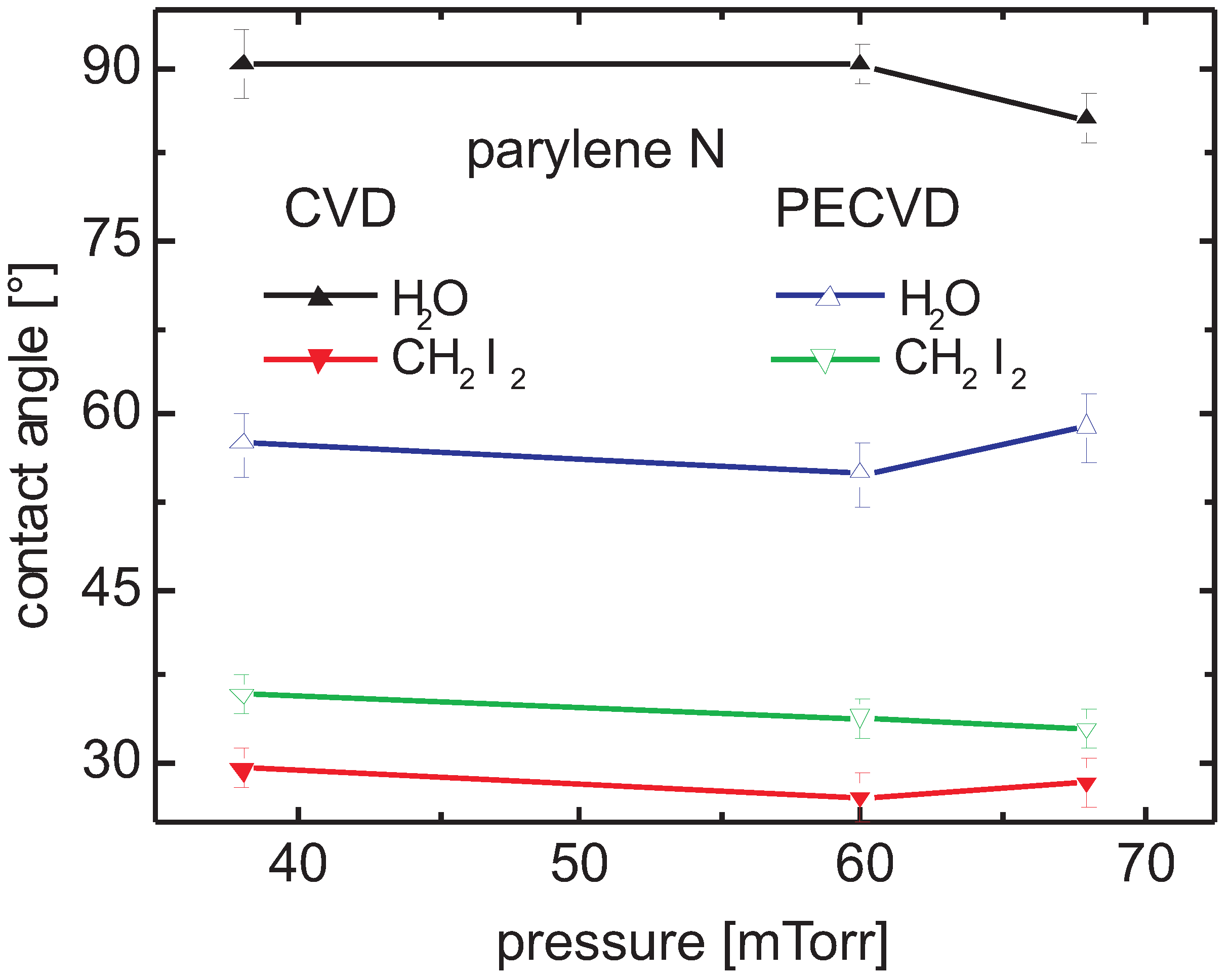
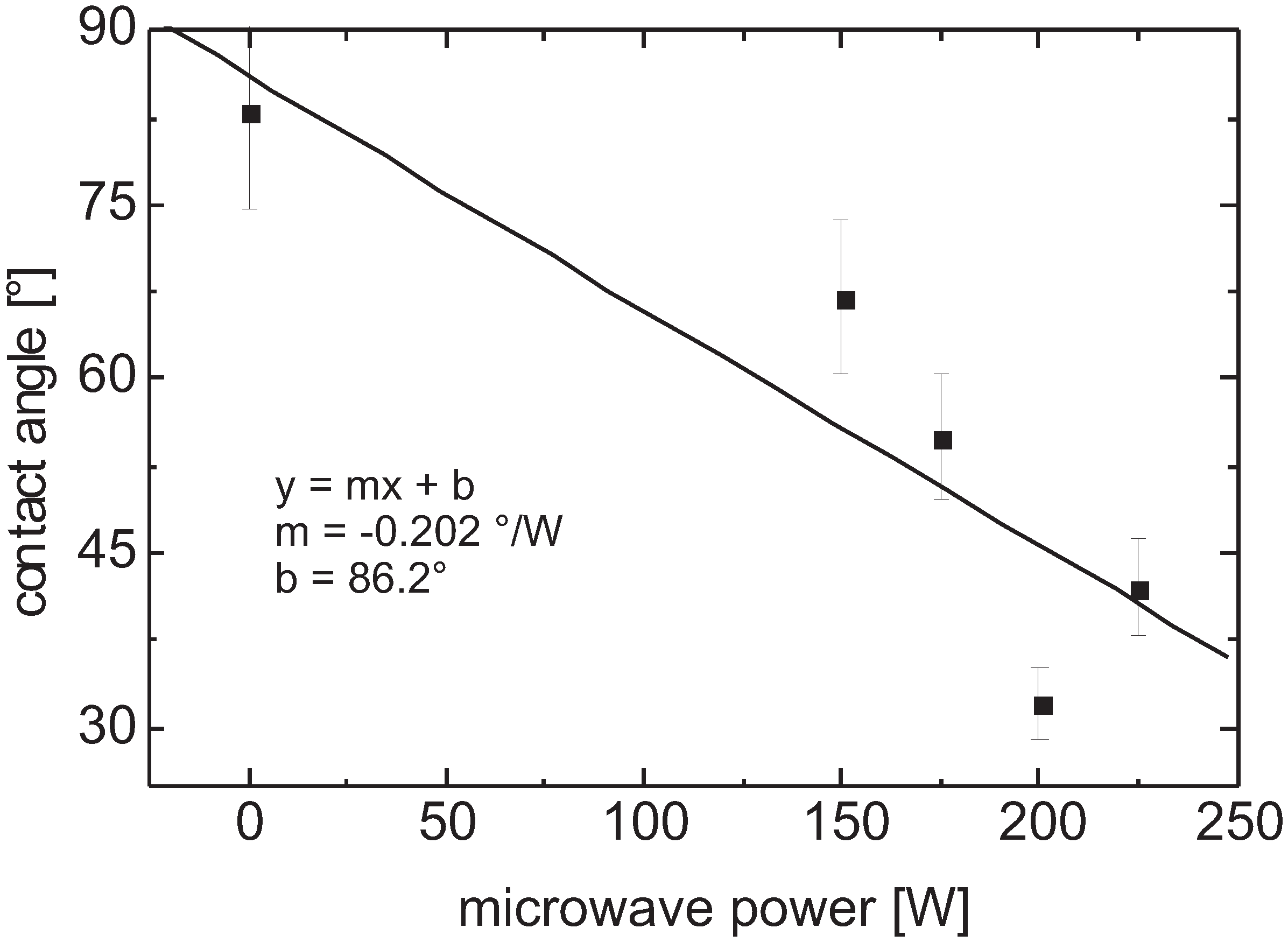
3.5.1. Parylene N
Contact Angle and Surface Energy

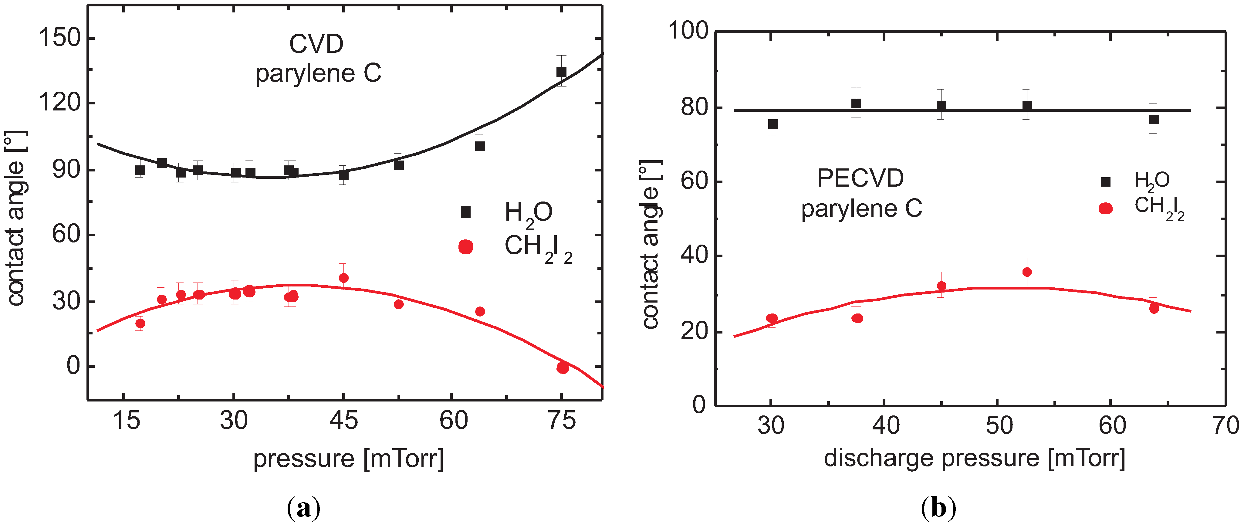
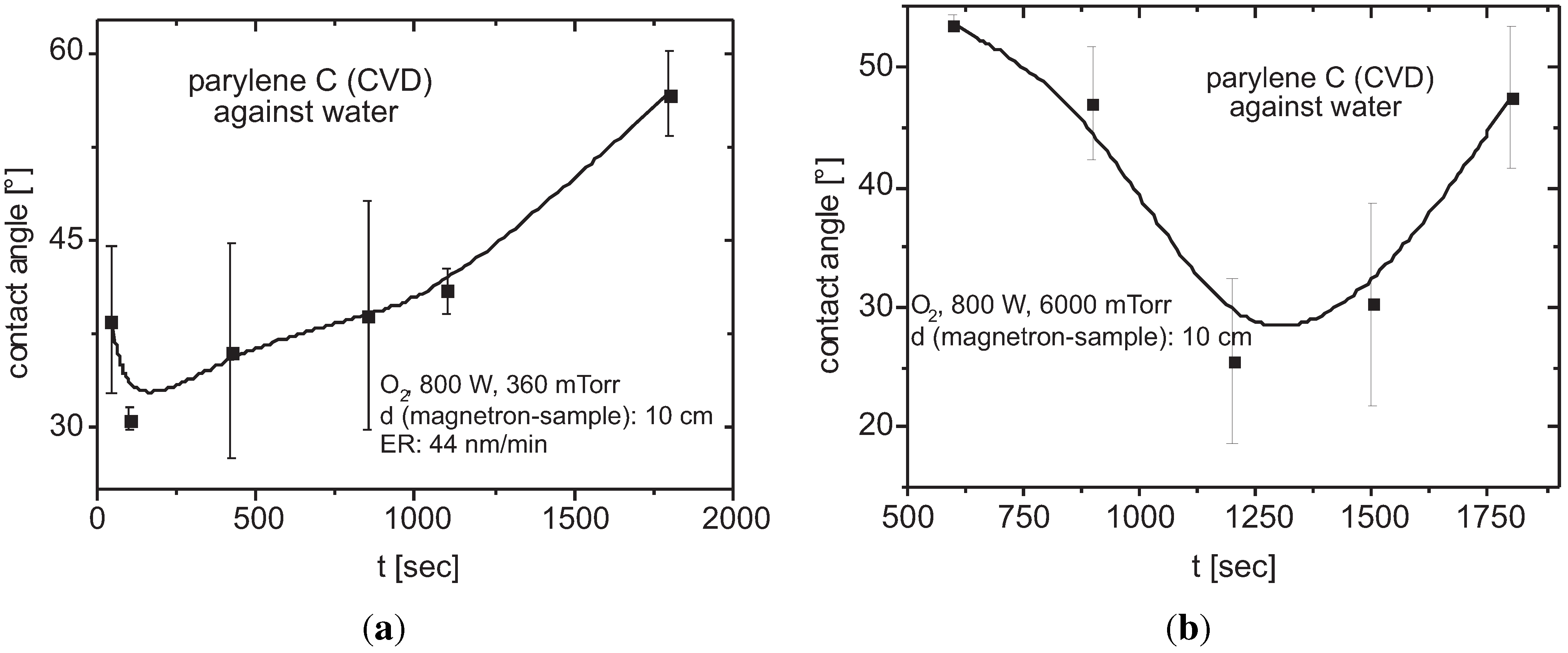
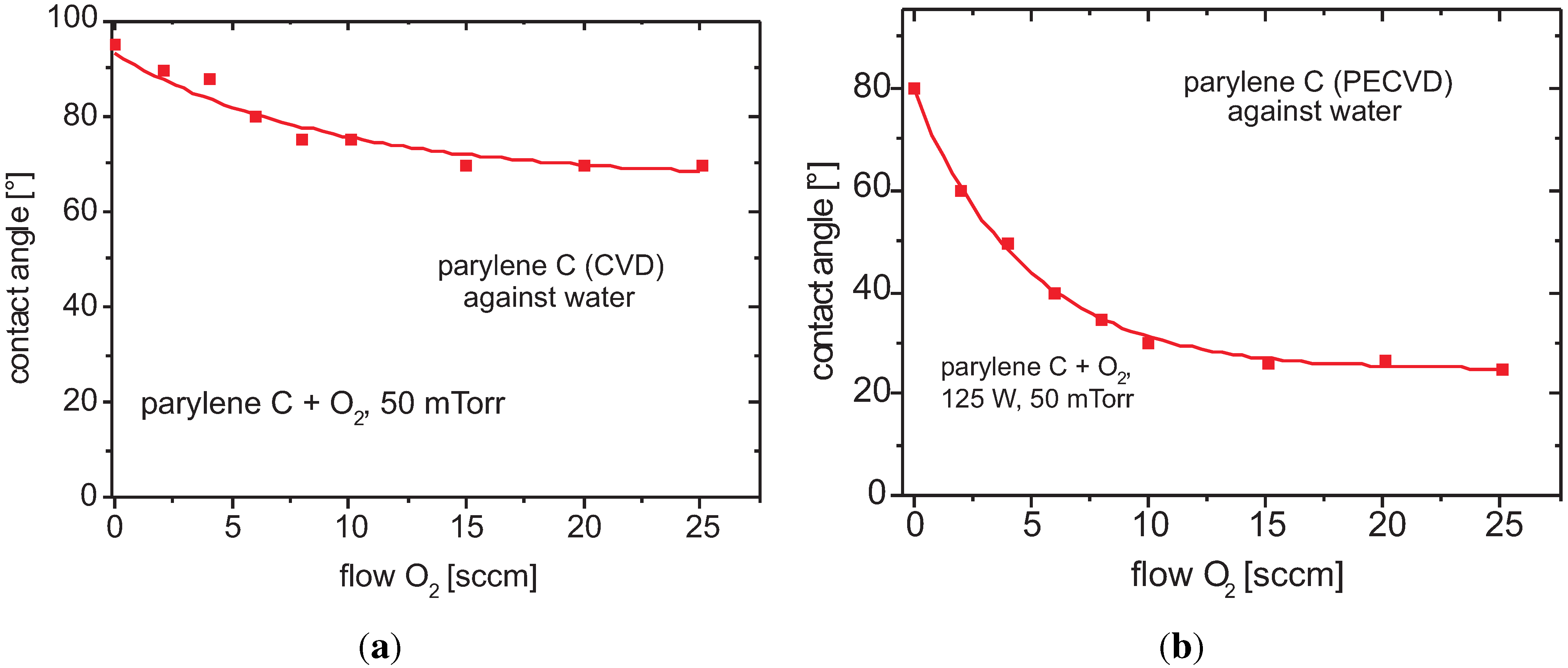
3.5.2. Parylene C
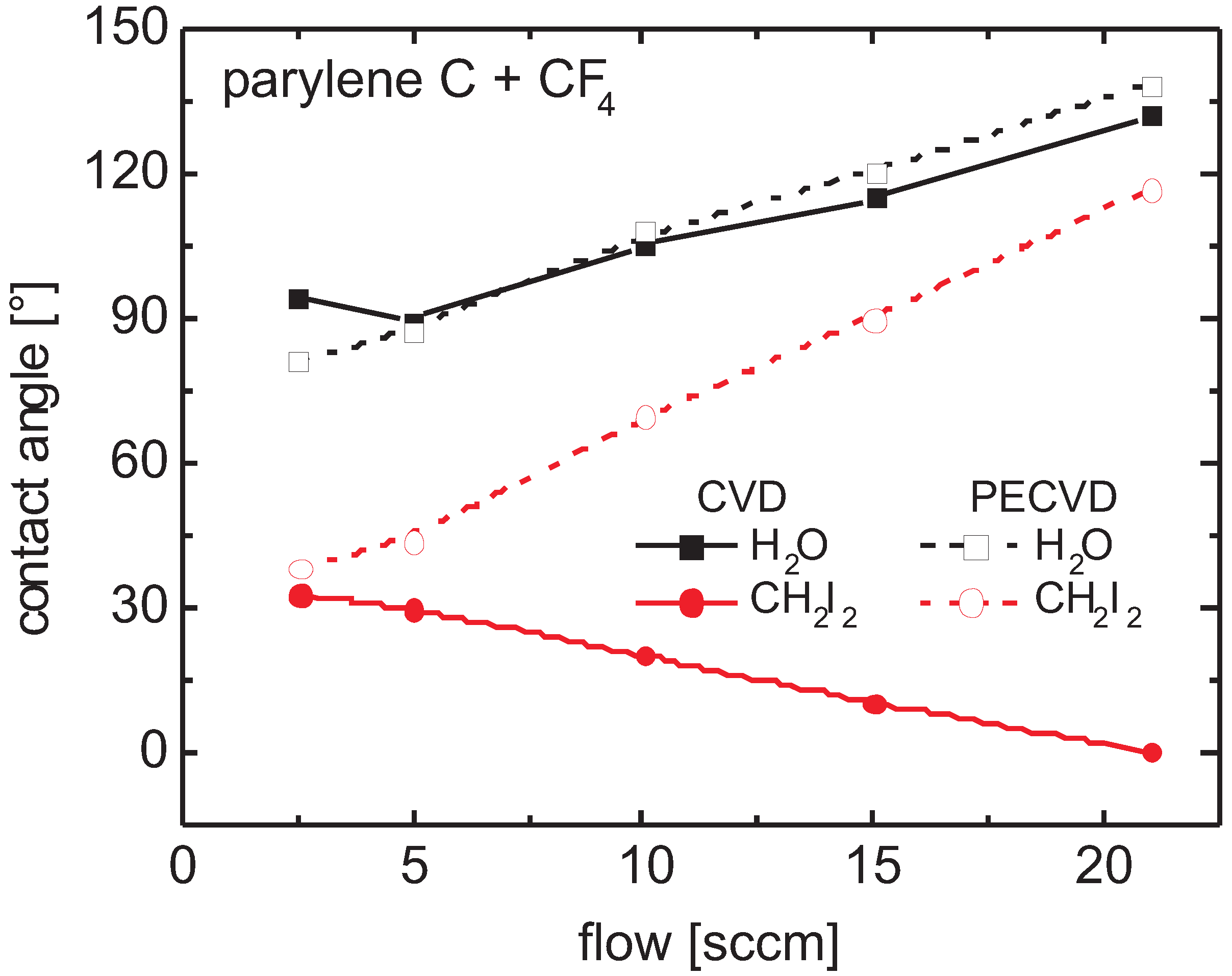
Contact Angle


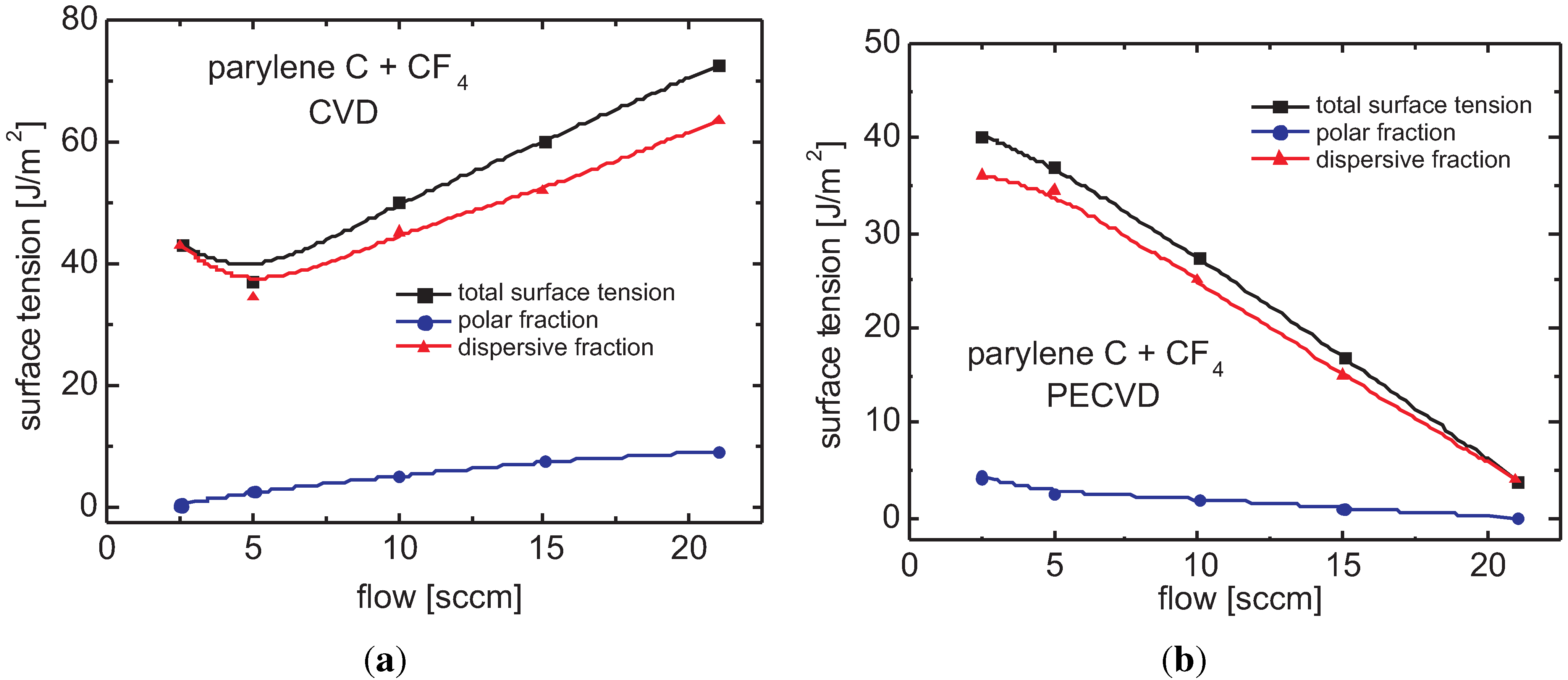
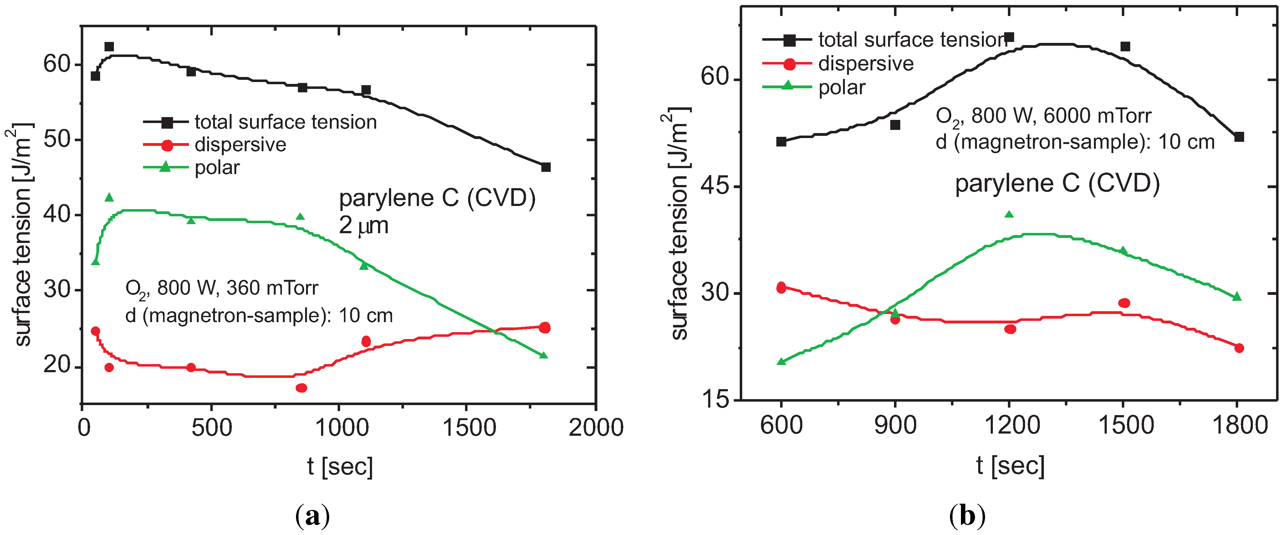
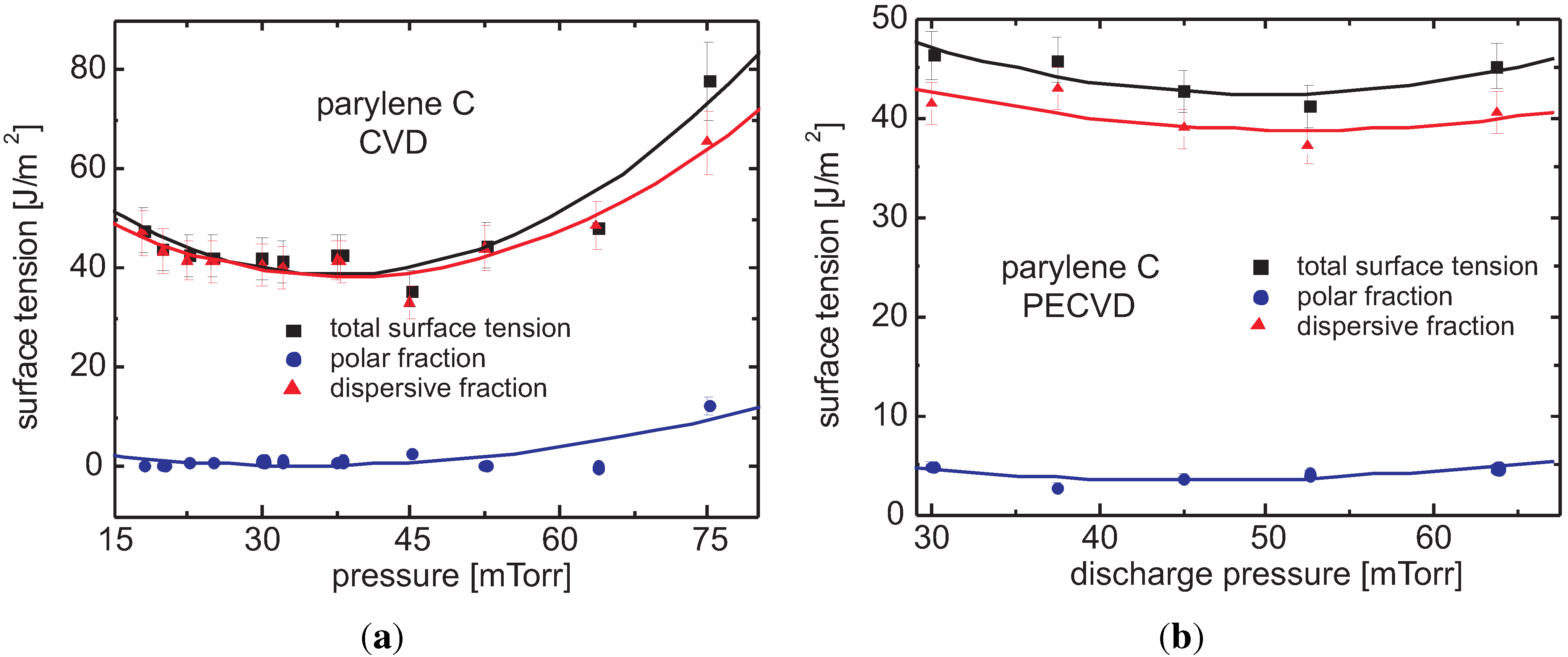
Surface Tension
3.6. Surface Behavior
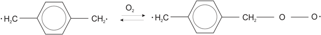
3.6.1. Incorporation of Hydrophilic Groups
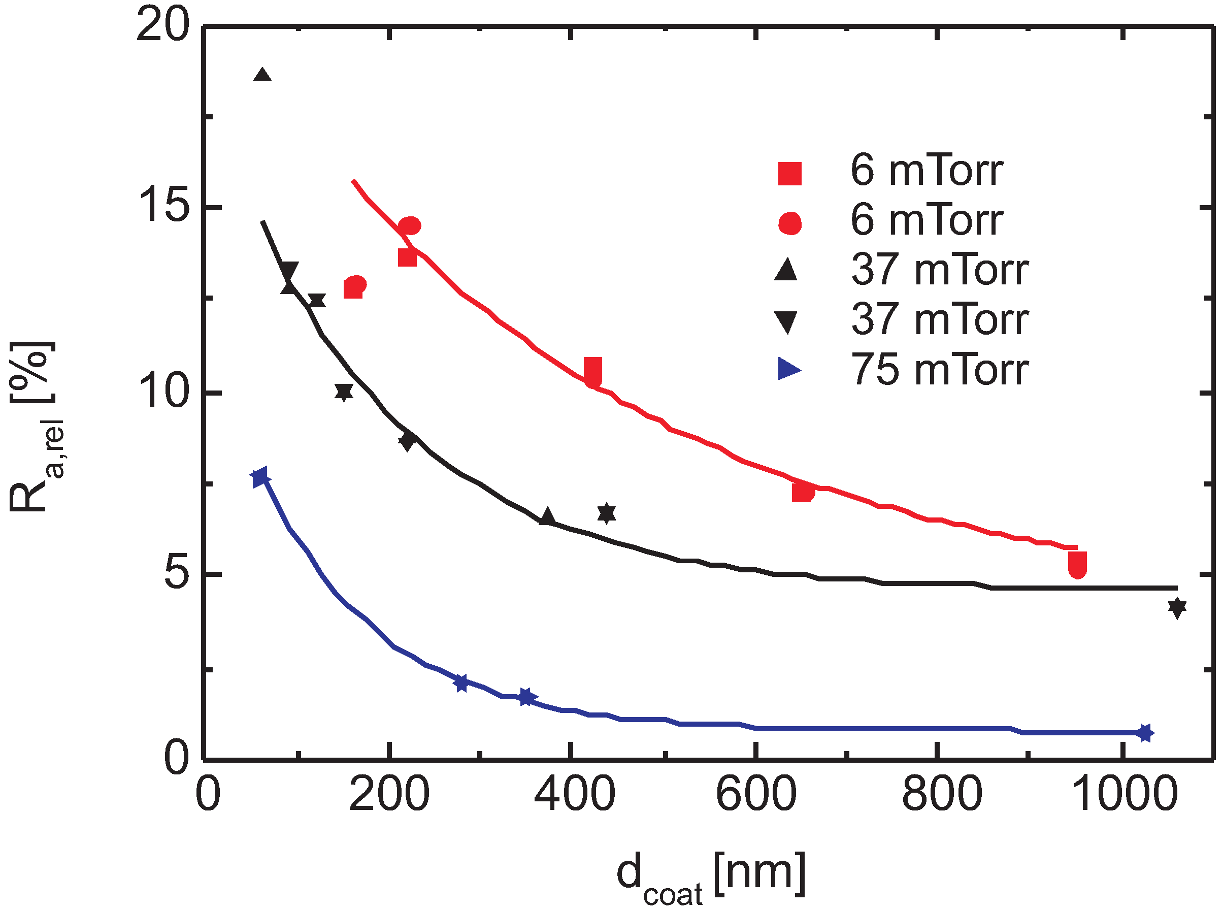
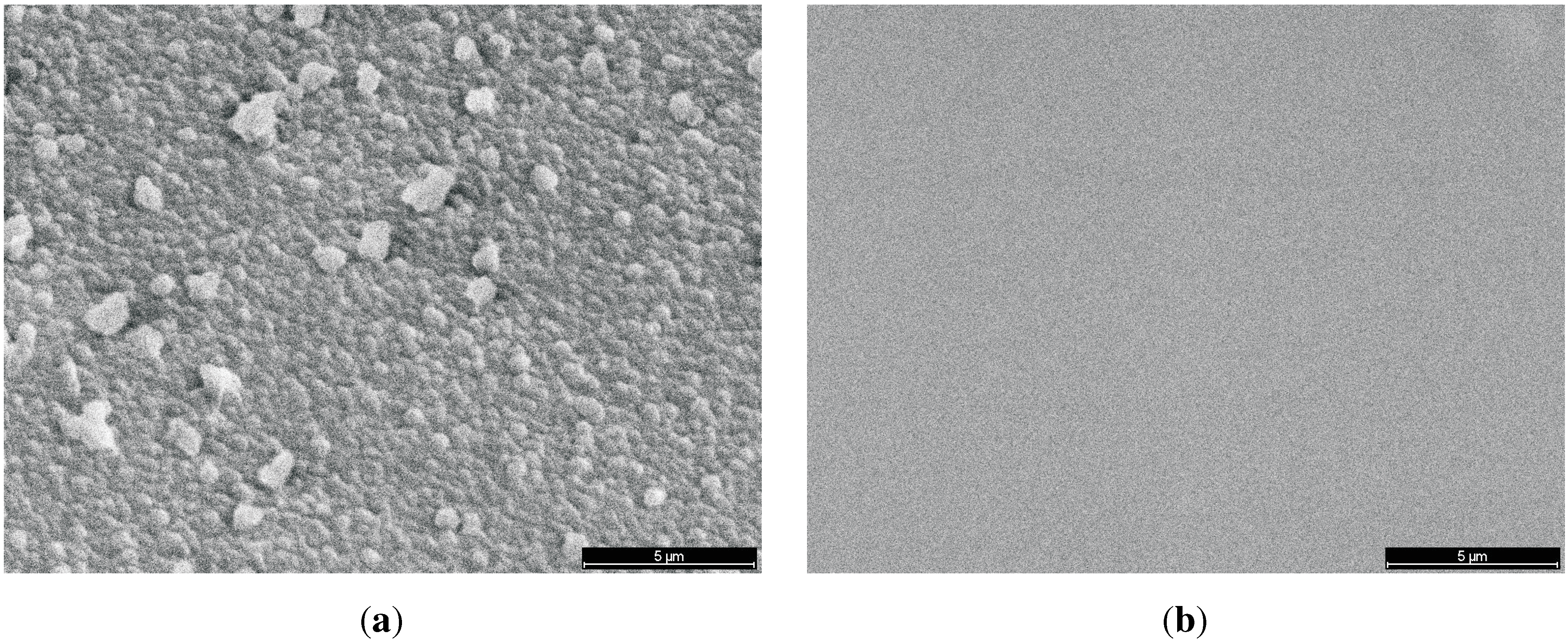
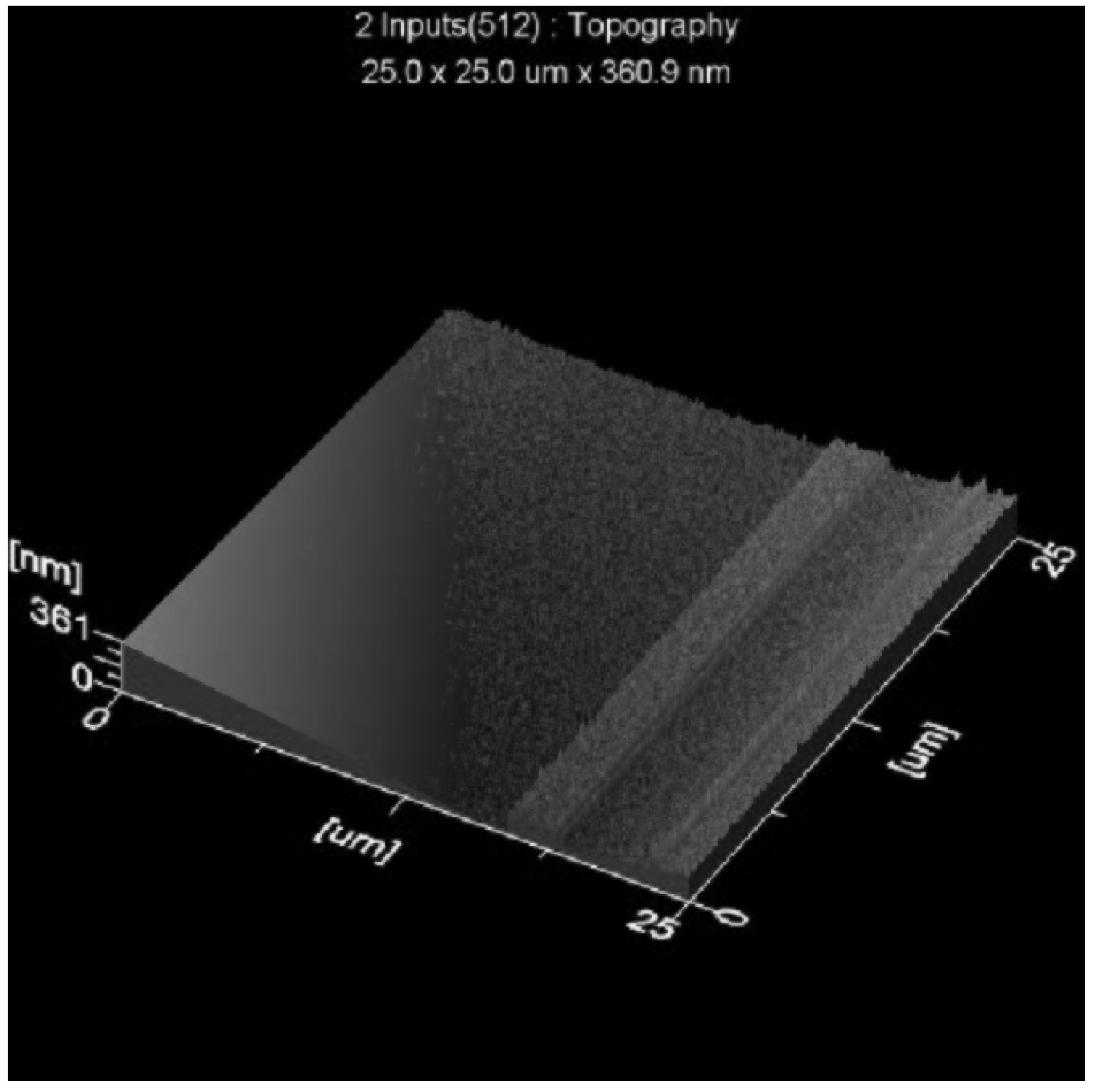
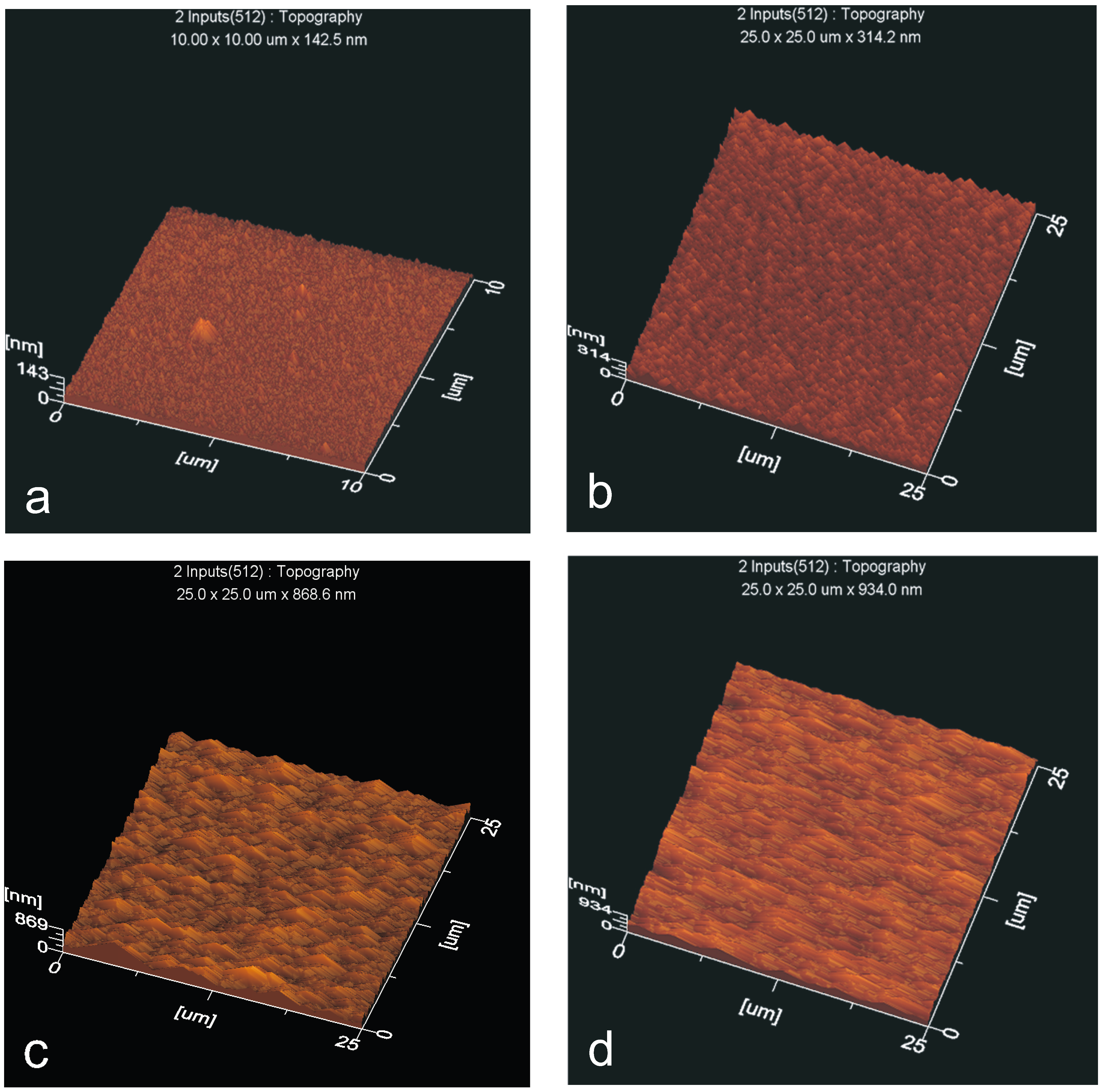
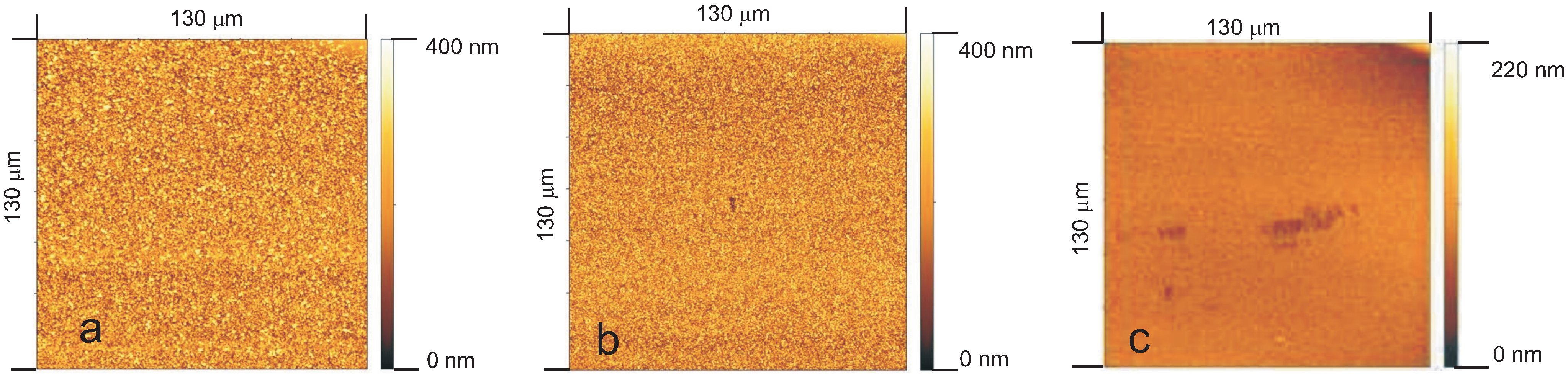
3.6.2. Surface Roughness
- polar groups that terminate the chains at the surface and
- the smoother surfaces of PECVD layers,
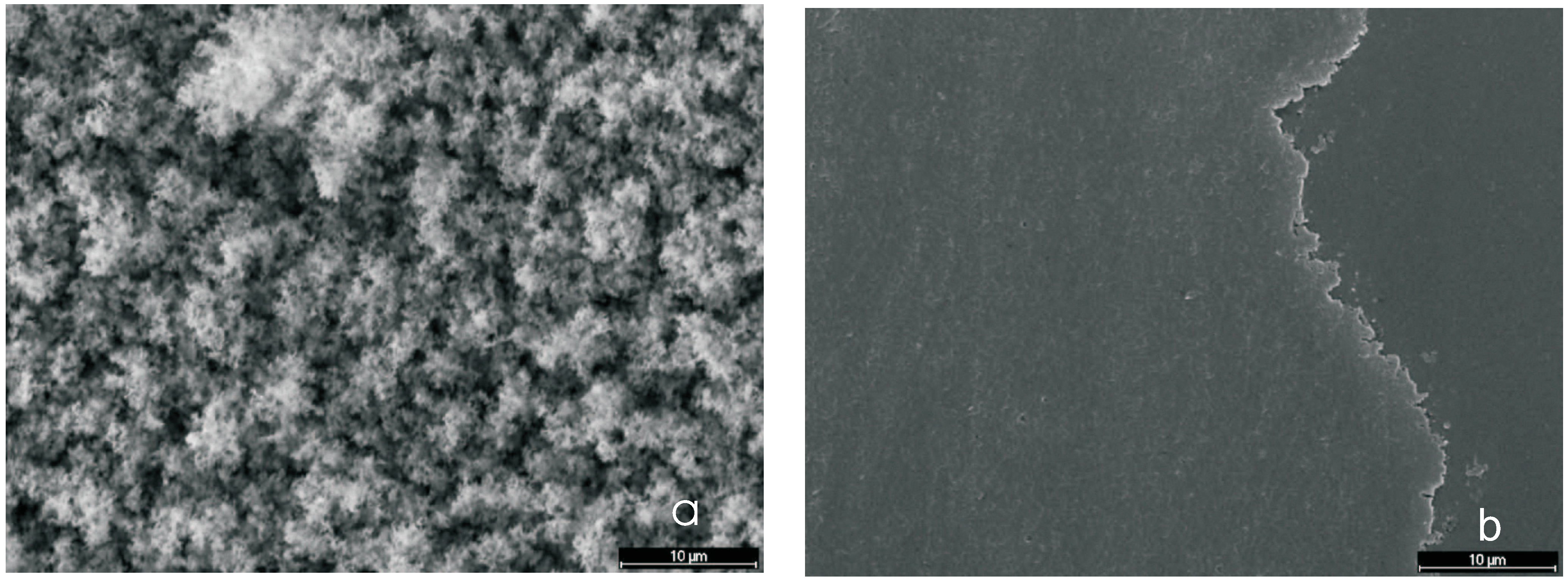
3.6.3. Super-Hydrophobic Surfaces
Contact Angle and Surface Energy


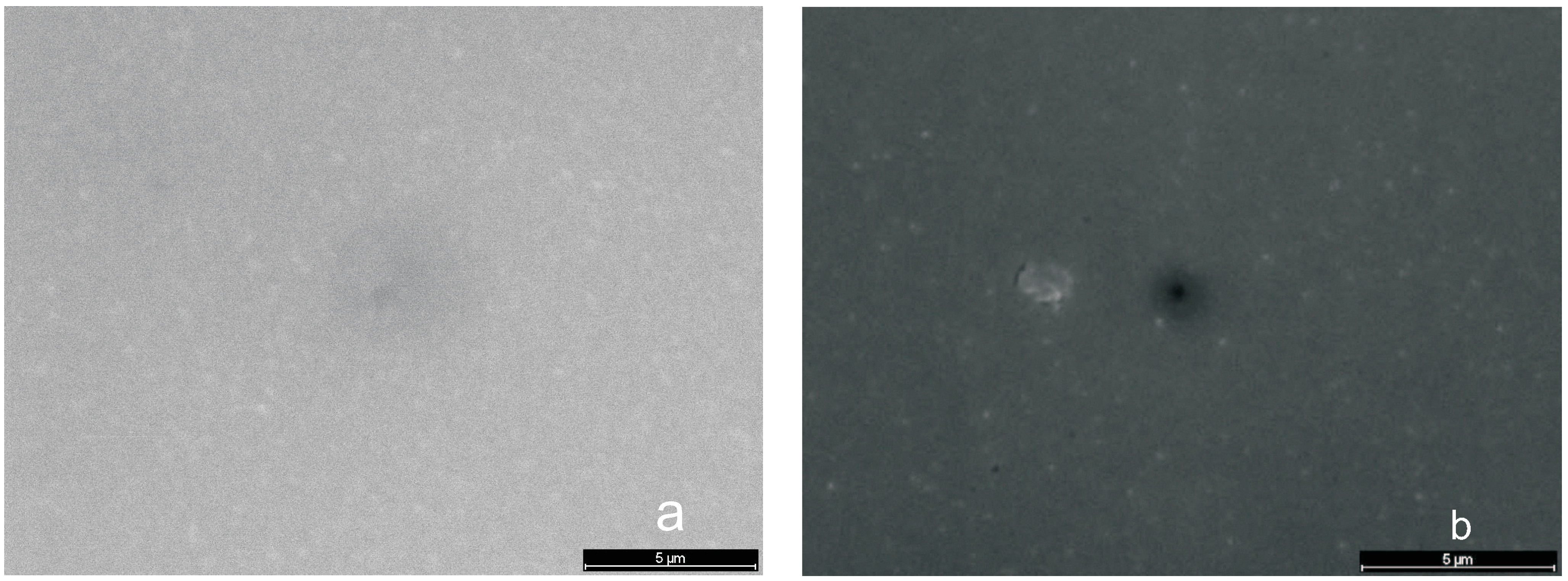
Micrographs (SEM)
3.6.4. Functionalization to Hydrophilic Surfaces

4. Conclusions
Acknowledgment
Author Contributions
Conflicts of Interest
References
- Fortin, J.B.; Lu, T.-M. The Growth and Properties of Parylene Thin Films; Kluver Academic Publishers: Dordrecht, Netherlands, 2004. [Google Scholar]
- Odian, G. Principles of Polymerization, 4th ed.; Wiley-Interscience: New York, NY, USA, 2004. [Google Scholar]
- Zhang, X.; Dabral, S.; Chiang, C.; McDonald, J.F. Crystallinity properties of parylene-N affecting its use as an ILD in submicron integrated circuit technology. Thin Solid Films 1995, 270, 508–512. [Google Scholar] [CrossRef]
- Yasuda, H. Plasma polymerization; Academic Press Inc.: New York, NY, USA, 1985. [Google Scholar]
- Yang, G.R.; Ganguli, S.; Karcz, J.; Gill, W.N.; Lu, T.M. High deposition rate parylene films. J. Cryst. Growth 1998, 183, 385–390. [Google Scholar] [CrossRef]
- Franz, G. Plasma roughening of polished SiC substrates. Mater. Sci. Semicond. Process. 2003, 5, 525–531. [Google Scholar] [CrossRef]
- Tserepi, A.D.; Vlachopoulou, M.-E.; Gogolides, E. Nanotexturing of poly(dimethylsiloxane) in plasmas for creating robust super-hydrophobic surfaces. Nanotechnology 2006, 17, 3977–3983. [Google Scholar] [CrossRef]
- Kokkoris, G.; Constantoudis, V.; Angelikopoulos, P.; Boulousis, G.; Gogolides, E. Dual nanoscale roughness on plasma-etched Si-surfaces: Role of etch inhibitors. Phys. Rev. B 2007, 76. [Google Scholar] [CrossRef]
- Lu, B; Lin, J.C.-H.; Liu, Z; Lee, Y.-K.; Tai, Y.-C. Highly flexible, transparent and patternable parylene-C superhydrophobic films with high and low adhesion. In Proceedings of 24th International Conference MEMS, Cancun, Mexico, 23–27 January 2011; pp. 1143–1146.
- Morris, J.R. Electrosurgical instrument having a parylene coating. U.S. Patent 5,380,320 A, 9 November 1993. [Google Scholar]
- Vitek Research Corporation. Parylene coating. Available online: http://vitekres.com/coatings/parylene-coatings (accessed on 5 May 2015).
- Hanyaloglu, B.; Aydinli, A.; Oye, M.; Aydil, E.S. Low dielectric constant Parylene-F-like films for intermetal dielectric applications. Appl. Phys. Lett. 1999, 74, 606–608. [Google Scholar] [CrossRef]
- Juneja, S.; Ten Eyck, G.A.; Bakruand, H.; Lu, T.-M. Pressure dependent Parylene-N pore sealant penetration in porous low-κ dielectrics. J. Vac. Sci. Technol. B 2005, 23, 2232–2235. [Google Scholar] [CrossRef]
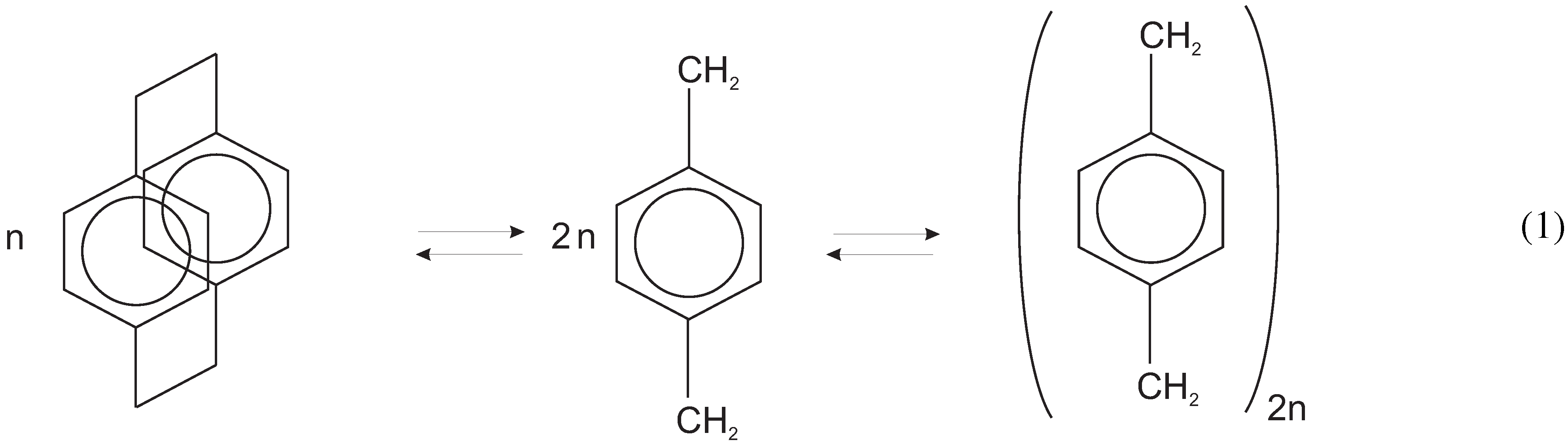
- Gorham, W.F. A new, general synthetic method for preparation of linear poly-pxylylenes. J. Polym. Sci. A 1966, 4, 3027–3039. [Google Scholar] [CrossRef]
- Demirel, M.C.; Cetinkaya, M.; Singh, A.; Dressick, W. A Non-covalent method for depositing nanoporous metals via spatially organized poly(p-xylylene) films. Adv. Mater. 2007, 19, 4495–4499. [Google Scholar] [CrossRef]
- Cetinkaya, M. Synthesis and Characterization of Nanostructured Poly-(p-xylylene) Films. Ph.D. Thesis, Pennsylvania State University, Pittsburgh, PA, USA, 2008. [Google Scholar]
- Stahl, U. Entwicklung eines Verfahrens zur Stabilisierung von Polymerschichten auf OFW-Sensoren für die Analytik von organischen Gasen. Ph.D. Thesis, Techn. University of Karlsruhe, Karlsruhe, Germany, 1999. [Google Scholar]
- Lin, T.J.; Chun, B.H.; Yasuda, H.K.; Yang, D.J.; Antonelli, J.A. Plasma polymerized organosilanes as interfacial modifiers in polymer-metal systems. J. Adhes. Sci. Technol. 1991, 5, 893–901. [Google Scholar] [CrossRef]
- Ishaque, M. Poly(p-xylylene): Synthesen, Strukturen, Eigenschaften und spezielle Anwendungsgebiete. Ph.D. Thesis, Philipps-Universität, Marburg/Lahn, Germany, 1999. [Google Scholar]
- Yasuda, H.; Chun, B.H.; Cho, D.L.; Lin, T.J.; Yang, D.J.; Antonelli, J.A. Interface-engineered parylene C coating for corrosion protection of cold-rolled steel. Corrosion 1996, 52, 169–176. [Google Scholar] [CrossRef]
- Ganguli, S.; Agrawal, H.; Wang, B.; McDonald, J.F.; Lu, T-M.; Yang, G.-R.; Gill, W.N. Improved growth and thermal stability of parylene films. J. Vac. Sci. Technol. A 1997, 15, 3138–3142. [Google Scholar] [CrossRef]
- Franz, G.; Schamberger, F.; Voss, D. Druckgesteuerte Abscheiderate. German Patent Disclosure DE 2012 014 915.8, 29 July 2012. [Google Scholar]
- Franz, G.; Schamberger, F. Evaporation and thermal cracking of dimeric parylenes. J. Vac. Sci. Technol. A 2013, 31, 061602:1–061602:8. [Google Scholar] [CrossRef]
- Kammer, S.; Wien, S.; Koch, K.P.; Robitzki, A.; Stieglitz, T. Untersuchungen zur Abscheidung von Parylen C als Kapselungsmaterial für biomedizinische Mikroimplantate — Coating material of parylene C as encapsulation material for biomedical micro-implants. Biomedizin. Technol. 2002, 47, 823–830. [Google Scholar] [CrossRef]
- Greiner, A.; Mang, S.; Schäfer, O.; Simon, P. Poly(1,4-xylylene)s: Synthesis, polymer analogeous reactions, and perspectives on structure-property relationsships. Acta Polym. 1997, 48, 1–15. [Google Scholar] [CrossRef]
- Simon, P.; Mang, S.; Hasenhindl, A.; Gronski, W.; Greiner, A. Poly(1,4-xylylene) and its derivatives by chemical vapor deposition: Synthesis, mechanism, and structure. Macromolecules 1998, 31, 8775–8780. [Google Scholar] [CrossRef]
- Ishaque, M.; Agrarwal, S.; Greiner, A. Synthesis and properties of novel poly(p-xylylene)s with aliphatic substituents. e-Polymers 2002, 31, 442–451. [Google Scholar] [CrossRef]
- Falbe, J.; Regitz, M. Römpp Chemie Lexikon; Georg Thieme Verlag: Stuttgart, Germany, 1995. [Google Scholar]
- Gerhartz, W.; Elvers, B. Ullmanns Enzyklopädie der technischen Chemie 15, 4th ed.; Verlag Chemie: Weinheim/Bergstraße, Germany, 1992; p. 432. [Google Scholar]
- Franz, G.; Rauter, F.; Dribinskiy, S.F. Characterization of microwave plasmas for deposition of polyparylene. J. Vac. Sci. Technol. A 2009, 27, 1035–1041. [Google Scholar] [CrossRef]
- Schamberger, F.; Ziegler, A.; Franz, G. Influence of film thickness and chemical vapor deposition rate on surface quality of polyparylene coatings. J. Vac. Sci. Technol. B 2012, 30, 051801:1–051801:6. [Google Scholar] [CrossRef]
- Franz, G.; Kelp, A.; Meßerer, P. Analysis of chlorine-containing plasmas applied in III/V semiconductor processing. J. Vac. Sci. Technol. A 2000, 18, 2053–2061. [Google Scholar] [CrossRef]
- Franz, G. Comprehensive analysis of capacitively coupled chlorine-containing plasmas. J. Vac. Sci. Technol. A 2005, 23, 369–387. [Google Scholar] [CrossRef]
- Kaelble, D.H. Physical Chemistry of Adhesion; John Wiley: New York, NY, USA, 1971. [Google Scholar]
- Rogojevic, S.; Moore, J.A.; Gill, W.N. Modeling vapor deposition of low-K polymers: Parylene and polynaphtalene. J. Vac. Sci. Technol. A 1999, 17, 266–274. [Google Scholar] [CrossRef]
- Blackburn, E.V.; Timmons, C.J. The photocyclisation of stilbene analogues. Quart. Rev. 1969, 23, 482–503. [Google Scholar] [CrossRef]
- Beach, W.F. A Model for the Vapor deposition polymerization of p-Xylylene. Macromolecules 1978, 11, 72–76. [Google Scholar] [CrossRef]
- Olson, R. Xylylene polymers. In Encyclopedia of Polymer Science and Engineering, 2nd ed.; Wiley: New York, NY, USA, 1989; Volume 17, pp. 990–1024. [Google Scholar]
- Mitu, B.; Bauer-Gogonea, S.; Leonhartsberger, H.; Lindner, M.; Bauer, S.; Dinescu, G. Plasma-deposited parylene-like thin films: process and material properties. Surf. Coat. Technol. 2003, 174–175, 124–130. [Google Scholar]
- Streitwieser, A., Jr.; Ward, H.R. Organic compounds in microwave discharges: II. Initial studies with toluene and related hydrocarbons. J. Am. Chem. Soc. 1963, 85, 539–542. [Google Scholar] [CrossRef]
- Wertheimer, M.R.; Moisan, M. Comparison of microwave and lower frequency plasmas for thin film deposition and etching. J. Vac. Sci. Technol. A 1985, 3, 2643–2649. [Google Scholar] [CrossRef]
- Moisan, M.; Barbeau, C.; Claude, R.; Ferreira, C.M.; Margot, J.; Paraszczak, J.; Sá, A.B.; Sauvé, G.; Wertheimer, M.R. Radio frequency or microwave plasma reactors? Factors determining the optimum frequency of operation. J. Vac. Sci. Technol. B 1991, 9, 8–25. [Google Scholar] [CrossRef]
- Cassie, A.B.D.; Baxter, S. Wettability of porous surfaces. Trans. Faraday Soc. 1944, 40, 546–550. [Google Scholar] [CrossRef]
- Wenzel, R.N. Resistance of solid surfaces to wetting by water. Ind. Eng. Chem. 1936, 28, 988–994. [Google Scholar] [CrossRef]
- Hwang, K.S.; Park, J.H.; Lee, J.H.; Yoon, D.S.; Kim, T.S.; Han, I.; Noh, J.H. Effect of atmospheric-plasma treatment for enhancing adhesion of Au on parylene-C-coated protein chips. J. Korean Phys. Soc. 2004, 44, 1168–1172. [Google Scholar]
- Senkevich, J.J.; Mitchell, C.J.; Vijayaraghavan, A.; Barnat, E.V.; McDonald, J.F. Unique structure/properties of chemical vapor depositied parylene E. J. Vac. Sci. Technol. A 2002, 20, 1445–1451. [Google Scholar] [CrossRef]
- Coburn, J.W.; Winters, H.F. Plasma etching—A discussion of mechanisms. J. Vac. Sci. Technol. 1979, 16, 391–403. [Google Scholar] [CrossRef]
- Shin, Y.S.; Cho, K.; Lim, S.H.; Chung, S.; Park, S.-J.; Chung, C.; Han, D.-C.; Chang, J.K. Pdms-based micro PRC chip with parylene coating. J. Micromech. Microeng. 2003, 13, 768–774. [Google Scholar] [CrossRef]
- Pruden, K.G.; Sinclair, K.; Beaudoin, S. Characterization of parylene-N and parylene-C photooxidation. J. Polym. Sci. Part A Polym. Chem. 2003, 41, 1486–1496. [Google Scholar] [CrossRef]
- Zhuang, Y.X.; Menon, A. Wettability and thermal stability of fluorocarbon films deposited by deep reactive ion etching. J. Vac. Sci. Technol. A 2005, 23, 434–439. [Google Scholar] [CrossRef]
- Yeo, J.; Choi, M.J.; Kim, D.S. Robust hydrophobic surfaces with various micropillar arrays. J. Micromec. Microeng. 2010, 20. [Google Scholar] [CrossRef]
- Bi, X.; Crum, B.P.; Li, W. Super hydrophobic parylene-C produced by consecutive O2 and SF6 plasma treatment. J. Microelectromech. Sys. 2014, 23, 628–635. [Google Scholar] [CrossRef]
- Liston, E.M.; Martinu, L.; Wertheimer, M.R. Plasma surface modification of polymers for improved adhesion: A critical review. J. Adhesion Sci. Technol. 1993, 7, 1091–1127. [Google Scholar] [CrossRef]
- Liston, E.M. Plasma treatment for improved bonding: A review. J. Adhesion 1989, 30, 199–218. [Google Scholar] [CrossRef]
- Tsougeni, K.; Petrou, P.S.; Tserepi, A.; Kakabakos, S.E.; Gogolides, E. Nano-texturing of poly(methyl metacrylate) polymer using plasma processes and applications in wetting control and protein absorption. Microelectron. Eng. 2009, 86, 1424–1427. [Google Scholar] [CrossRef]
© 2015 by the authors; licensee MDPI, Basel, Switzerland. This article is an open access article distributed under the terms and conditions of the Creative Commons Attribution license (http://creativecommons.org/licenses/by/4.0/).
Share and Cite
Reichel, A.; Franz, G.; Amann, M.-C. Correlation of Growth and Surface Properties of Poly(\(p\)-xylylenes) to Reaction Conditions. Coatings 2015, 5, 142-171. https://doi.org/10.3390/coatings5020142
Reichel A, Franz G, Amann M-C. Correlation of Growth and Surface Properties of Poly(\(p\)-xylylenes) to Reaction Conditions. Coatings. 2015; 5(2):142-171. https://doi.org/10.3390/coatings5020142
Chicago/Turabian StyleReichel, Andreas, Gerhard Franz, and Markus-Christian Amann. 2015. "Correlation of Growth and Surface Properties of Poly(\(p\)-xylylenes) to Reaction Conditions" Coatings 5, no. 2: 142-171. https://doi.org/10.3390/coatings5020142
APA StyleReichel, A., Franz, G., & Amann, M.-C. (2015). Correlation of Growth and Surface Properties of Poly(\(p\)-xylylenes) to Reaction Conditions. Coatings, 5(2), 142-171. https://doi.org/10.3390/coatings5020142