Article

Morphology and Wear Resistance of Laser-Clad Fe-Cr-Nb-C Alloy Coatings

by
Min Chen
1,2,
Haoran Zhou
1,
Xuyang Liu
3,*,
Zhongxue Feng
4,*,
Xuan Xiao
1,
Liu Weng
1,
Yang Yang
1 and
Yan Jiang
1
1
Vanadium and Titanium Critical Strategic Materials Key Laboratory of Sichuan Province, Panzhihua University, Panzhihua 617000, China
2
Sichuan Vanadium&Titanium Industrial Technology Institute, Panzhihua 617000, China
3
College of Aerospace Engineering, Chongqing University, Chongqing 400044, China
4
Faculty of Materials Science and Engineering, Kunming University of Science and Technology, Kunming 650093, China
*
Authors to whom correspondence should be addressed.
Coatings 2025, 15(9), 1055; https://doi.org/10.3390/coatings15091055
Submission received: 7 August 2025 / Revised: 23 August 2025 / Accepted: 1 September 2025 / Published: 8 September 2025
(This article belongs to the Section Laser Coatings)

Abstract

Fe-Cr-Nb-C wear-resistant alloy coatings were successfully fabricated on high-carbon forged steel via coaxial powder feeding laser cladding. The evolution of microstructure and wear resistance with varying Nb content was systematically investigated. The results indicate that appropriate NbC addition markedly modifies the distribution of grain and boundary carbides. As Nb content increases from 2.5 wt% to 3.5 wt%, nanoscale rod-like NbC precipitates form uniformly along boundaries, effectively suppressing the formation of brittle Cr23C6 precipitation. Semi-coherent NbC/matrix interfaces and NbC-induced grain refinement reduce adhesive/abrasive wear, thereby improving hardness and wear resistance. At 4.5 wt% Nb, discrete micron-sized NbC particles form within the grains, yielding optimal performance. However, excessive Nb (≥5.5 wt%) causes NbC agglomeration, inducing stress concentrations and large spallation pits that deteriorate wear resistance. This work highlights NbC morphology as a key factor for tailoring coating properties.

1. Introduction

Carbon steel is widely used in engineering machinery components owing to its favorable mechanical properties. However, it is prone to wear and fatigue under harsh service conditions, leading to performance degradation or premature failure [1,2,3,4]. Laser cladding of iron-based wear-resistant coatings on carbon steel surfaces has emerged as an effective strategy to address these challenges. This technique not only facilitates the repair of failed components—facilitating resource recycling—but also significantly enhances surface wear resistance compared to the base substrate, thereby extending service life. Unlike the fabrication of new parts, laser cladding technology enables precise, localized repairs with reduced resource consumption, lower energy input, and a smaller carbon footprint [5,6,7,8,9]. The incorporation of carbides into iron-based laser-clad coatings can significantly improve hardness and wear resistance [10,11,12,13], particularly when exogenous carbide reinforcement phases are introduced [14,15,16]. Previous studies have explored the direct addition of carbides such as TiC, WC, and NbC into iron-based coatings to improve mechanical performance [17,18,19]. Among these, NbC is notable for its density closely matching that of iron-based matrices, promoting uniform distribution, and its excellent wettability with iron-based alloys, improving microstructural compatibility [20,21]. However, the extreme thermal conditions during laser cladding, where heating rates exceed thousands of degrees per second, can cause partial or complete decomposition of carbide particles. This releases carbon and strong carbide-forming elements, which may recombine during rapid cooling to form new carbides, profoundly influencing the coating’s final properties [22,23,24].
Cao et al. [25] reported that ex situ NbC particles partially decompose during laser processing, releasing Nb and C atoms into the melt. Some Nb atoms dissolve into the matrix or form Fe2Nb, reducing the final NbC content. Undecomposed NbC particles act as heterogeneous nucleation sites, promoting the reprecipitation of NbC in eutectic forms, which enhances hardness and wear resistance. However, ex situ carbide particles often exhibit poor chemical stability under a non-equilibrium solidification process, leading to interfacial stress concentrations due to mismatches in elastic modulus, thermal expansion, and lattice structure, ultimately reducing toughness and crack resistance. In contrast, in situ formed carbides exhibit better interfacial bonding and reduced lattice mismatch, mitigating thermal stress and improving coating performance [26,27,28]. Cao et al. [29] further examined in situ NbC formation using pre-placed Nb–Fe–B–Si–C powder mixtures, observing various NbC morphologies (particles, polyhedrons, dendrites, and networks) that critically influence coating stability. Compound-based carbon sources provide higher stability and controlled carbon release, enabling better regulation of NbC morphology. Chen et al. [30] successfully fabricated NbC-reinforced iron-based alloy coatings in situ using B4C as the carbon source, finding that petal-like NbC particles at grain boundaries refined the microstructure and improved properties. Commercial high-chromium iron-based wear-resistant materials typically rely on in situ chromium carbides for reinforcement. While the Fe-Cr matrix also offers good corrosion resistance, making high-chromium iron-based alloys widely applicable in various fields due to their high hardness, wear resistance, and corrosion resistance. However, the continuous distribution of chromium carbides along grain boundaries can lead to grain boundary embrittlement, reducing toughness and crack resistance.
Despite extensive research on carbide-reinforced Fe-based coatings, the role of Nb content in regulating the microstructure and wear behavior of laser-clad Fe–Cr–Nb–C coatings remains unexplored. In this work, we propose a novel strategy employing high-carbon ferrochrome and ferroniobium as primary sources for in situ NbC formation, which effectively suppresses the detrimental Cr23C6 phase and enhances grain boundary cohesion. By systematically varying the Nb content from 2.5 to 5.5 wt%, we demonstrate for the first time the transition in NbC morphology from nanoscale rods along grain boundaries to intragranular microparticles and its significant impact on coating hardness and tribological performance. This study not only addresses a critical gap in understanding Nb-mediated microstructural evolution in Fe-based laser-clad coatings but also offers a practical approach for designing high-performance wear-resistant coatings tailored for high-carbon steel substrates.

2. Experimental Materials and Methods

2.1. Substrate and Raw Materials

A 60CrMnMo steel plate (chemical composition: Fe-0.58C-0.70Mn-0.17Si-0.15Mo-0.03S-0.03P, all in wt%) with dimensions of 150 mm × 150 mm × 20 mm was employed as the substrate. Alloying coatings were fabricated on the substrate surface via laser cladding technology. The cladding powders were primarily composed of High-carbon ferrochromium (150 μm, Cr: 69.31 wt%, C: 8.51 wt% and the rest is Fe.), Low-carbonferrochromium (150 μm, Cr: 68.27 wt%, C: 0.1 wt% and the rest is Fe.), ferroniobium (100 μm, Nb: 65 wt%, Si: 2.67 wt%, C: 0.07 wt% and the rest is Fe), spherical pure iron powder (53~150 μm purity greater than 99.99 wt%), ferro-molybdenum (150 μm, Mo: 38.58 wt%, Si: 0.76 wt%, C: 0.07 wt% and the rest is Fe), and ferrosilicon (50 μm, Si: 73.46 wt%, C: 0.05 wt% and the rest is Fe). Four sets of laser cladding experiments with different Nb contents are designed. A V-type mixer was employed to blend powders with varying designed niobium contents at a rotational speed of 60 r/min for 10 h to ensure homogeneous mixing. The total mass of the uniformly mixed powder was 500 g. After mixing, the powder is placed in a drying oven and dried at a constant temperature of 120 °C for 2 h to ensure that the powder has good fluidity and stability. The final coating thickness is approximately 3 mm. The powder composition of the design (Table 1) is as follows.
Laser cladding was performed using a Laserline LDF 6000-60 laser system, with the schematic of the coating fabrication process illustrated in Figure 1. The key processing parameters were as follows: laser power 2200 W, scanning speed 12 mm/s, and powder feed rate 6 r/min. A coaxial powder feeding mechanism was employed to ensure uniform material delivery. Before the experiment, the sample surface was first ground as a whole using an Angle grinder. The rust on the substrate surface was removed by using the RFL-P300 handheld laser cleaning system (Laser power is 300 W), and then the surface contaminants were wiped with ethanol. These preparatory steps were performed to prevent the formation of pores, inclusions, and other defects within the coating. After the cladding process, the samples were sectioned using a wire electrical discharge machining (EDM) system into specimens with dimensions of 10 mm × 10 mm × 10 mm and 30 mm × 30 mm × 5 mm. The former were used for coating composition analysis, phase identification, and microstructural characterization, while the latter were employed for hardness and wear performance evaluations.

2.2. Experimental Procedures

Coating composition was analyzed using a direct-reading optical emission spectrometer (ARL 4460, Thermo Fisher, Waltham, MA, USA), operated in spark excitation mode with a focal length of 1000 mm and a wavelength range of 160–650 nm. The cross-sectional surfaces of the specimens were sequentially ground using 800 to 1200 grit metallographic abrasive papers, mechanically polished, and etched with HCl acid (36%–38%): HNO3 acid (69%) (1:4 volume ratio). Microstructure was examined using an optical microscope (Zeiss AxioCam 506, Carl Zeiss AG, Oberkochen, Germany) and a scanning electron microscope (SEM, EVO 18, ZEISS, Carl Zeiss AG, Oberkochen, Germany). A compositional analysis of local regions within the cladding layer was performed via point analysis and area mapping using the attached energy-dispersive X-ray spectroscopy (EDS, X-Max, Oxford Instruments, Abingdon, UK) system.
Phase identification of the coating was conducted using an X’Pert Powder X-ray diffractometer (XRD, D8 Advance, Bruker, Karlsruhe, Germany) with Cu Kα radiation (λ = 1.5406 Å) operated at 40 kV. The XRD measurements were conducted at 40 kV with a step size of 0.02°, a scanning speed of 6°/min, and a 2θ range of 30°–100°. The thermodynamic equilibrium phase diagrams were calculated using JmatPro 14.0 software (Sente Software Ltd., Guildford, UK). Further examination of the nanoscale morphology and crystallographic structure of individual phases was conducted utilizing a transmission electron microscope (TEM, ARM-200F, JEOL Ltd., Tokyo, Japan). In this study, the TEM samples were prepared using a Gatan PIPS 691 focused ion beam (FIB) polishing system. Subsequently, Vickers hardness measurements were conducted using a Lidun HV-1000STA hardness tester. The load used was 200g, and the dwell time was set at 10 s. The hardness profile across the coating thickness was determined by performing measurements at multiple locations on cross-sectional samples. Specifically, measurements were taken at varying distances from the coating surface, starting from the top surface of the coating, passing through the heat-affected zone (HAZ), and extending into the substrate. The hardness values obtained were then statistically analyzed to evaluate the distribution of hardness across the entire coating-substrate interface. Finally, Polished tribological specimens with varying Nb contents were subjected to room-temperature dry sliding wear tests on an MVF-1A tribometer in a ball-on-disc configuration to investigate the effect of Nb content on the wear performance of the cladding layer. Three high-speed steel balls were arranged in a triangular pattern to ensure stable contact during testing and improve data reliability. All wear tests were conducted under a constant load of 80 N and a rotation speed of 200 r/min.

2.3. Computational Methods

Interfacial mismatch between MC carbides and the martensitic matrix (α′-Fe) or M23C6 was evaluated using Bramfitt’s two-dimensional lattice mismatch theory:
δ h kl n h kl s = 1 3 i = 1 3 d uvw s i cos θ - d uvw n i d uvw n i   ×   100 %
Where (hkl)s denotes the low-index crystallographic plane of the matrix, and [uvw]s represents the corresponding low-index direction within this plane. Similarly, (hkl)n refers to the low-index plane of the newly formed solid phase, and [uvw]n is the low-index direction within (hkl)n. The terms d[uvw]s and d[uvw]n indicate the atomic spacings along [uvw]s and [uvw]n directions, respectively, while θ is the angle between these directions (0° ≤ θ ≤ 90°). When the lattice mismatch δ is less than 6%, the interface is considered highly coherent, providing the most favorable conditions for heterogeneous nucleation. When δ is between 6% and 12%, the interface shows moderate matching (semi-coherent interface), leading to moderately effective heterogeneous nucleation. When δ exceeds 12%, the interface has low matching (incoherent interface), and heterogeneous nucleation is generally ineffective.

3. Results and Discussion

3.1. Coating Composition and Phase Analysis

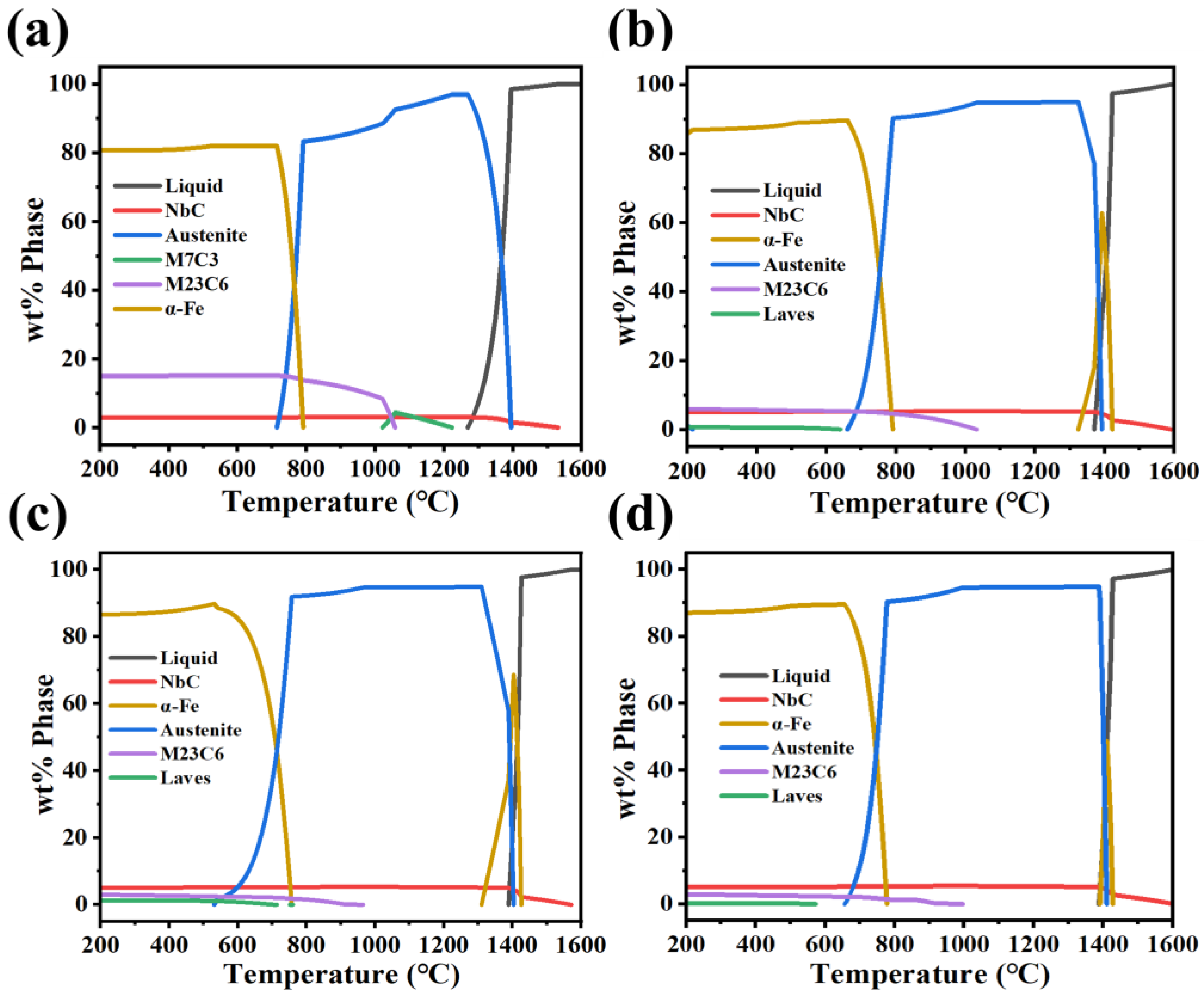
Figure 2 shows the calculated thermodynamic equilibrium phase diagrams of the iron-based alloy according to the composition in Table 1. In the presence of low Nb contents, Cr demonstrates a propensity to form M7C3-type carbides at elevated temperatures, which subsequently undergo a transformation into M23C6 precipitates during the cooling process. With the Nb content increases, the Cr primarily forms the M23C6 phase, suggesting that M23C6 exhibits higher thermodynamic stability than the M7C3 in this alloy system and is more stable in the microstructure. As the NbC content increases from 2.93 to 5.16 wt%, M23C6 decreases from 14.93 to 2.93 wt%, demonstrating that higher NbC concentrations effectively suppress M23C6 formation. Consequently, a greater proportion of Cr exists in solid solution within the matrix, resulting in an augmentation in the matrix phase fraction in the phase diagram. Furthermore, the elevated NbC content facilitates the formation of a small amount of NbFe2 Laves phase, suggesting a shift in the phase equilibrium dynamics with increasing Nb addition.
Figure 3 presents the XRD phase analysis results of coatings with different Nb contents. It primarily consists of the α’-Fe phase, Cr23C6, (Fe, Cr) solid solution, and NbC. It is evident that, due to the markedly elevated cooling rates (104–105 °C/s) that are characteristic of the rapid solidification process inherent to laser cladding, austenite undergoes direct transformation into a martensitic matrix via a diffusionless phase transformation. As the Nb content increases, the diffraction peak intensity of NbC gradually increases, while that of Cr23C6 progressively decreases. Concurrently, the intensity of the (Fe, Cr) solid solution peaks demonstrates an upward trend. In the Nb-D coating, the diffraction peak intensity of Cr23C6 is lower compared to the other phases. The XRD patterns show a clear predominance of NbC, α’-Fe phase, and (Fe, Cr) solid solution peaks, which reach their maximum intensities. This observation is in good agreement with the phase diagram calculations, indicating that NbC plays a dominant role in the microstructure of the Nb-D coating. The intensity of the Cr23C6 peak is significantly weaker, suggesting that its formation is suppressed in this coating.

3.2. Microstructure of Coatings

The metallographic microstructure of the in situ NbC-reinforced Fe-based alloy coatings fabricated by laser cladding is presented in Figure 4. The interfacial region between the coating and the substrate exhibits a distinct arc-shaped morphology. No cracks, pores, or other defects are observed in the fusion zone, indicating the formation of a sound metallurgical bond. With increasing Nb content, the amount of carbides precipitates along the grain boundaries rises progressively, and their distribution extends from the grain boundaries into the grain interiors. In the Nb-A coating, a limited strip-like carbide is visible along the grain boundaries. Conversely, the Nb-B coating shows a slight reduction in the quantity of such carbides, as indicated by the red arrows in Figure 4(a2,b2). The Nb-C coating is dominated by fine rod-like carbides, while the Nb-D coating contains a higher density of precipitated carbides with more uniform morphology, highlighted by yellow arrows in Figure 4(c2,d2).
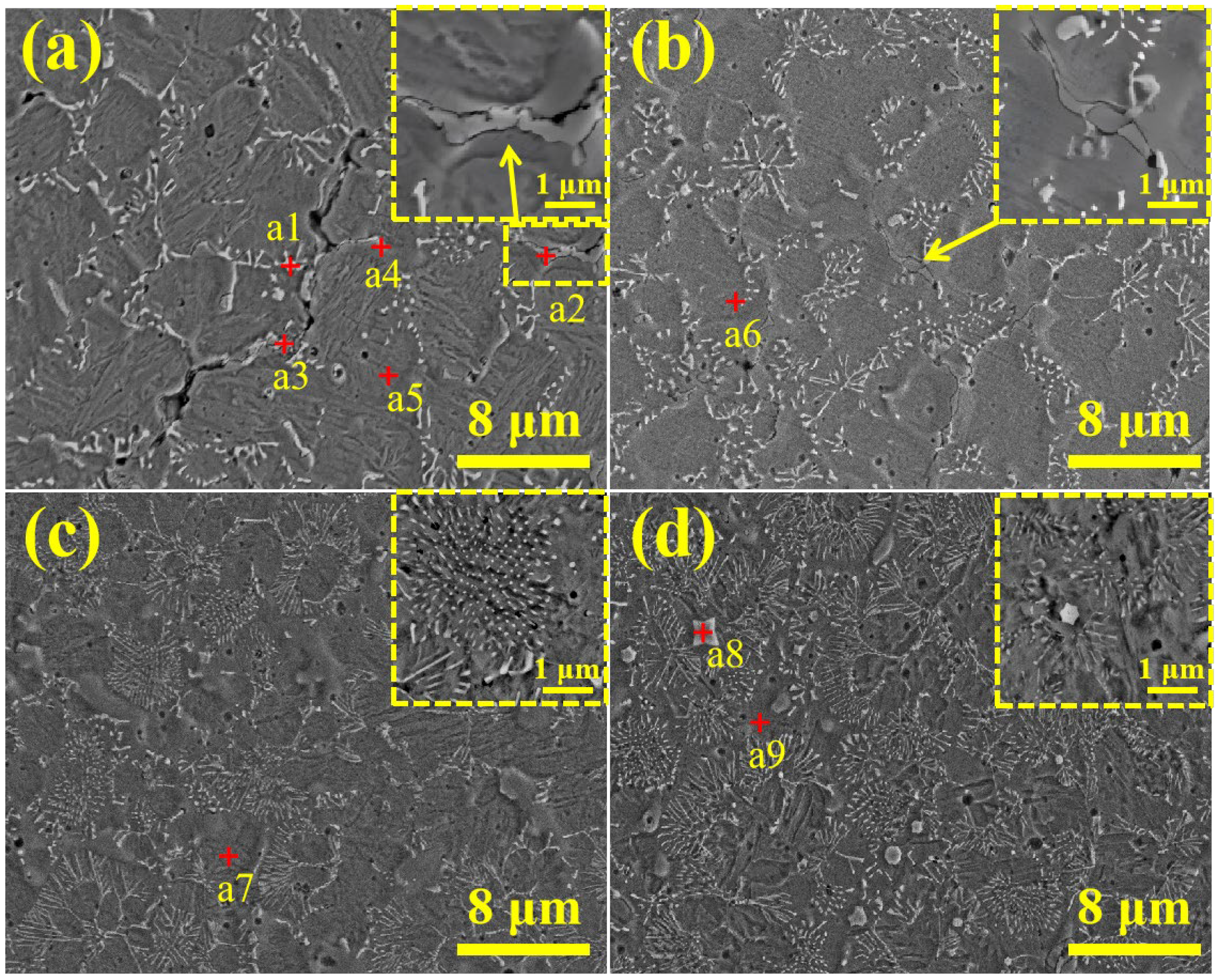
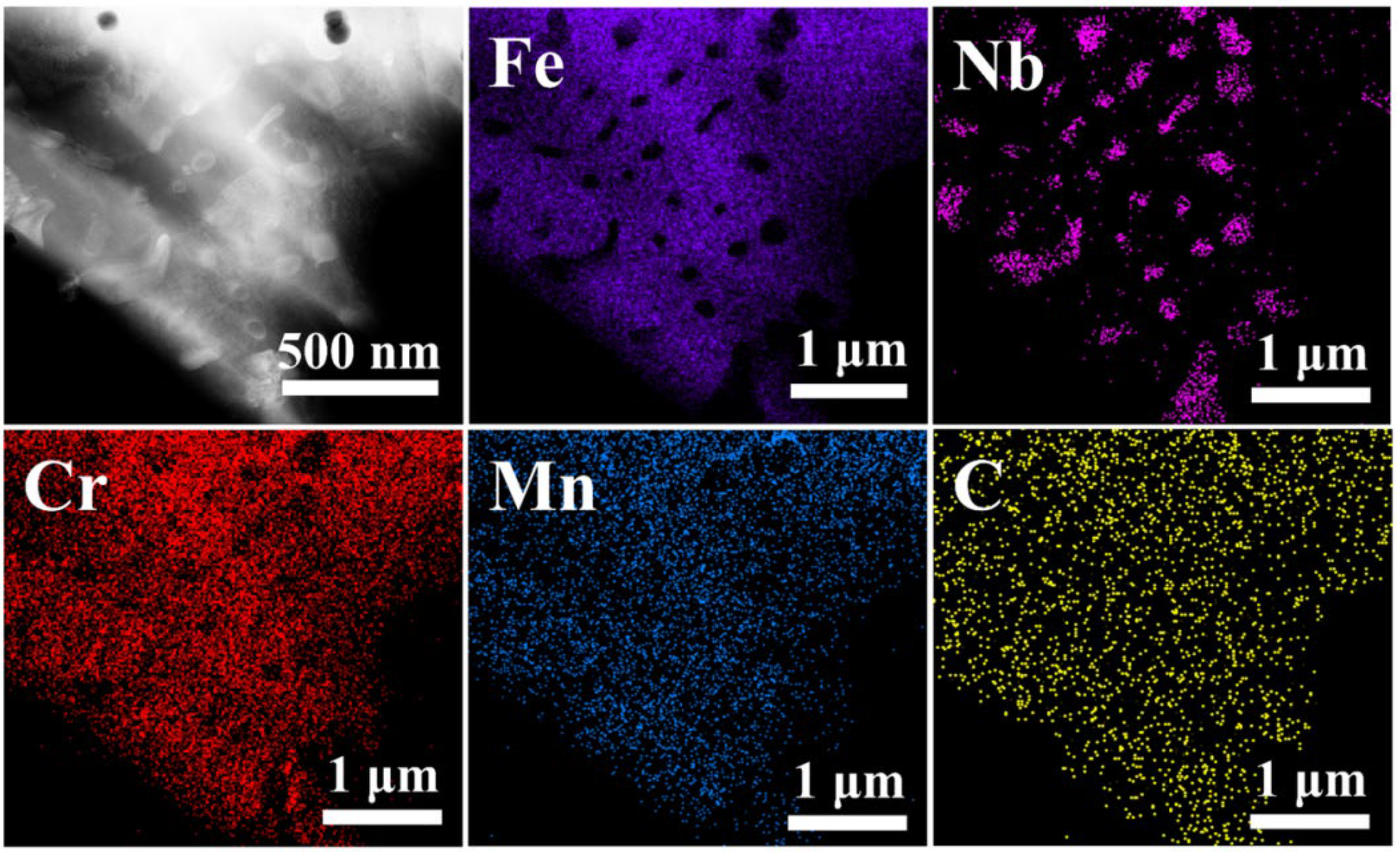
In order to conduct a more in-depth investigation into the effect of Nb content on the microstructural evolution of the coatings, high-magnification morphological analyses were conducted as shown in Figure 5 and Figure 6. The Nb-A coating exhibits a notable prevalence of strip-like carbides along the grain boundaries. This occurrence has been observed to result in a substantial enhancement of the coating’s brittleness, thereby leading to the formation of intergranular cracks along these grain boundaries. The Nb-B coating exhibits a decline in the number of strip-like carbides, accompanied by a gradual disappearance of intergranular cracks. A comparison between Figure 5a,b reveals that as the strip-like carbides decrease, the precipitation of skeletal primary phases at the grain boundaries increases noticeably. Energy-dispersive spectroscopy (EDS) analysis (Table 2) indicates that the strip-like carbides correspond to Cr23C6, while the skeletal primary phases are (Fe, Cr) solid solutions. This finding indicates that increasing Nb content promotes the migration of Cr from Cr23C6 into the (Fe, Cr) solid solution phase, thereby effectively suppressing the formation of Cr23C6 and mitigating intergranular cracking. Chen et al. [9] also reported that the addition of Nb effectively suppresses the precipitation of brittle Cr23C6 carbides at grain boundaries, thereby improving alloy toughness and reducing intergranular cracking. Their results are consistent with ours, confirming that the introduction of Nb can effectively limit the formation of Cr23C6. It is evident that an augmentation in the Nb content results in a substantial diminution of the precipitation of Cr23C6 at the grain boundaries. Finally, high-resolution transmission electron microscopy (TEM) surface scanning of rod-like precipitates enriched at the grain boundaries confirms that these precipitates are the NbC phase. This phenomenon is attributed to the substantial increase in NbC nucleation sites within the coating as the Nb content rises, thereby promoting the refinement of the rod-like NbC particles. Concurrently, Cr exists predominantly in solid solution within the matrix. In the Nb-D coating, fine NbC precipitates extend from the grain boundaries into the grain interiors. Additionally, uniformly shaped granular carbides are observed in NbC-enriched regions. EDS analysis confirms that these granular carbides are also the NbC phase. The preferential distribution of NbC along grain boundaries can be attributed to the solidification sequence within the molten pool. During the rapid solidification process inherent to laser cladding, NbC, due to its exceptionally high melting point, is among the first phases to nucleate and precipitate from the liquid melt. Subsequently, the Fe-based matrix solidifies around these pre-existing NbC particles. The advancing solid/liquid interface of the growing matrix grains effectively pushes the NbC particles towards the last solidifying regions, which are ultimately the grain boundaries.
Figure 6 displays high magnification scanning electron microscope (SEM) microstructures of laser-clad Fe-based alloy coatings with varying Nb contents, revealing a clear evolution in morphology. At lower Nb contents (2.5 wt% and 3.5 wt%), as shown in Figure 6a,b, both granular and rod-like NbC particles are relatively coarse, with sizes ranging approximately from 2.71 to 2.88 μm. As the Nb content increases, the number of NbC nucleation sites increases substantially, leading to a notable refinement in the size of these particles, now within the range of 0.17 to 1.00 μm. This refinement contributes to a more finely structured martensitic matrix and NbC reinforcement. With a further increase in Nb content to 5.5 wt%, as depicted in Figure 6d, Nb aggregation results in the formation of large polygonal NbC particles, which envelop finer rod-like and granular NbC phases. Figure 7 is the TEM-EDS mapping of the Nb-B coating, further confirming the elemental distribution in the above phases.

3.3. TEM Analysis

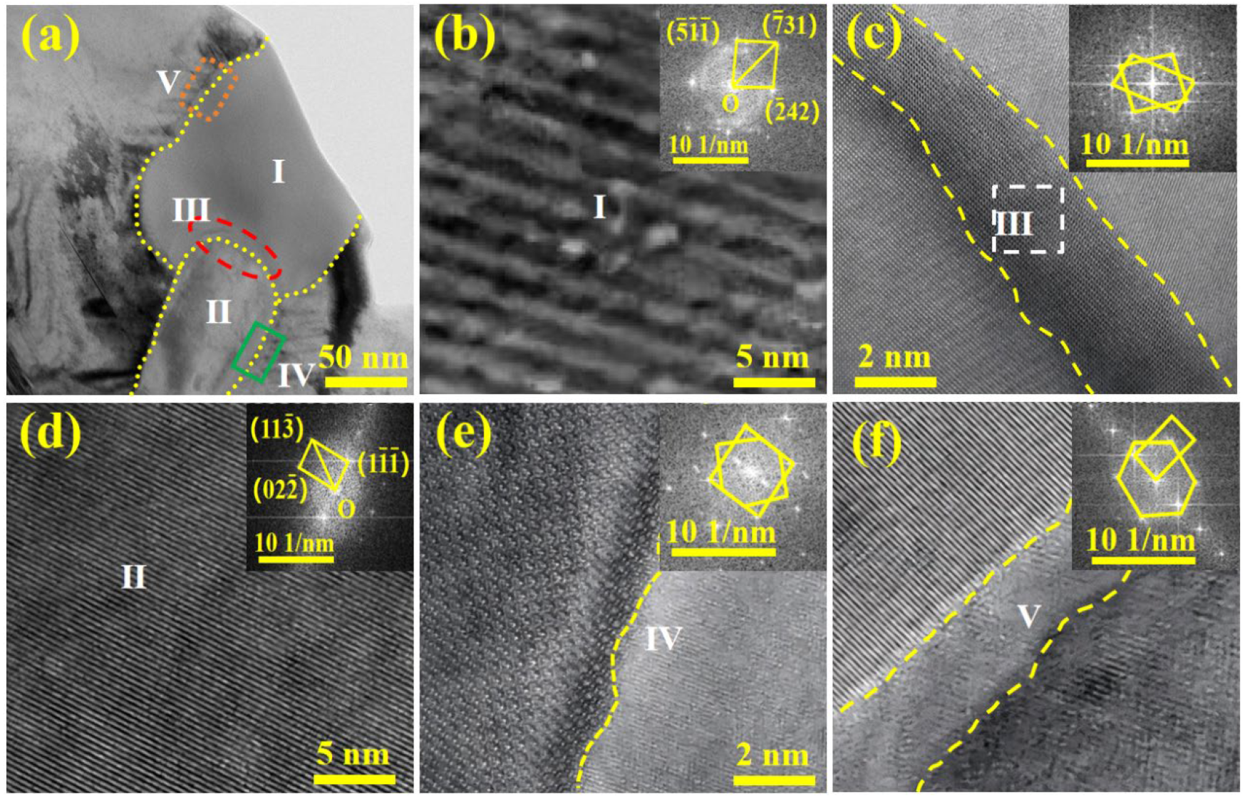
To examine the effect of NbC precipitates on Cr23C6 on grain boundaries and the martensite, phase identification was conducted using diffraction patterns obtained from high-resolution transmission electron microscopy (HRTEM). The crystal structures of the precipitated phases and the lattice mismatch at their interfaces with adjacent phases were determined through calibration of these patterns, as depicted in Figure 8. Indexing of the diffraction patterns identified Regions I as Cr23C6 and Region II as NbC. The lattice parameters of NbC were measured as 4.69 Å for NbC, 10.68 Å for Cr23C6, and 2.87 Å for α’-Fe (martensite). Regions Ⅲ, IV, and V correspond to interfacial transition zones between NbC/Cr23C6, NbC/martensite, and M23C6/martensite, respectively, where partial diffraction spot overlap is observed between adjacent phases.
The results of crystal structure matching calculations for the NbC/martensite and NbC/Cr23C6 interfaces are summarized in Table 3 and Table 4, respectively. The lattice mismatch for the (110)NbC || (100)α’-Fe interface is 11.56%, indicating a semi-coherent interface. This suggests that NbC can act as a heterogeneous nucleation core for the martensitic phase. As the Nb content increases, the number of NbC precipitates rises, with newly formed NbC particles serving as effective nucleation sites. Yang et al. [25] also demonstrated that NbC can serve as an effective heterogeneous nucleation site for martensite. Their diffraction and interface analysis revealed a similar degree of lattice matching between NbC and martensite, thereby promoting grain refinement. These results align well with our calculations, which further validate the reliability of the present findings. This not only leads to the refinement of the NbC particles themselves but also promotes the refinement of the martensitic matrix. Conversely, the (110)NbC || (011)Cr23C6 interface exhibits a higher mismatch of 12.19%, indicative of an incoherent interface. Consequently, NbC is improbable to function as a heterogeneous nucleation site for Cr23C6.

3.4. Microhardness Analysis

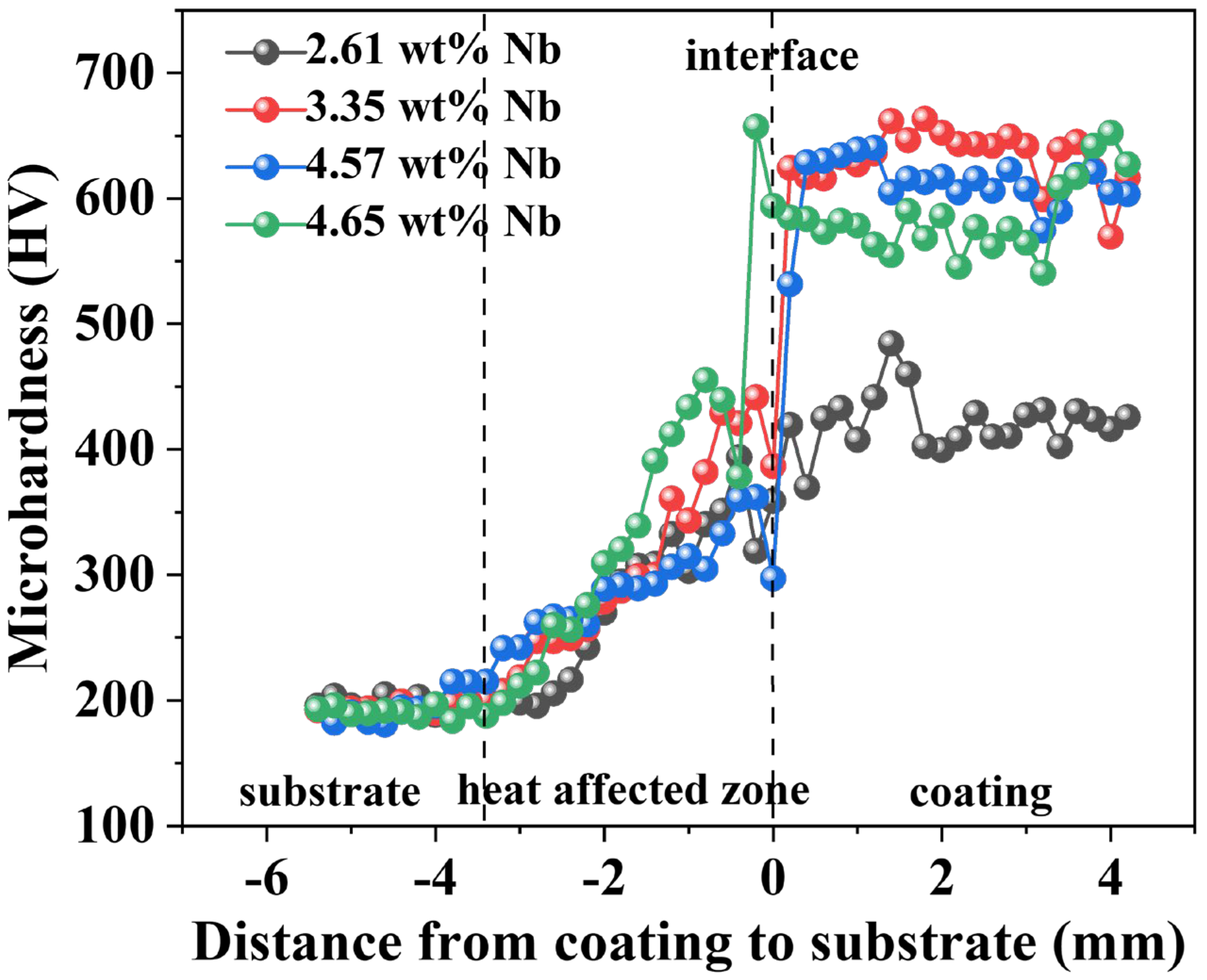
Figure 9 presents the microhardness distribution of laser-clad Fe-based alloy coatings containing varying Nb contents. The Vickers hardness of the coating increases gradually from the substrate toward the top surface. Within the heat-affected zone (HAZ), the hardness continues to increase until it reaches a stabilization state within the coating region. Coatings with lower Nb content contain limited amounts of the NbC phase. Given that NbC possesses significantly higher hardness than Cr23C6, the low proportion of NbC in the Nb-A coating results in a diminished overall hardness. As the Nb content increases, the NbC phase becomes more abundant, while Cr23C6 is substantially suppressed. This results in a marked enhancement in coating hardness. In the Nb-D coating, the diffraction peak intensity of NbC reaches its maximum, indicating the highest NbC content. Furthermore, the formation of large NbC particles occurs in regions that are locally enriched, thereby consuming carbon from the matrix and reducing its carbon content. Consequently, the overall hardness of the Nb-D coating undergoes a slight decrease. Previous studies also lend support to this observation. As reported by Cao et al. [29] and Chen et al. [19], during laser cladding of Fe-based alloys, Nb exhibits a high affinity for carbon and preferentially combines with C to form NbC. This preferential reaction depletes carbon from the matrix, thereby reducing the carbon available for solid solution strengthening of martensite. Consequently, when the Nb content becomes excessively high, coarse NbC particles form, and the matrix is impoverished in carbon. This weakens the solid solution strengthening effect and ultimately leads to a reduction in overall hardness. These findings align with the behavior observed in the Nb-D coating, where the hardness slightly decreases despite the increase in NbC content. It is observed that the hardness values of the Nb-B and Nb-C coatings are comparable, despite the increase in Nb content from 4 wt% (Nb-B) to 5 wt% (Nb-C). This similarity can be attributed to the progressive suppression of Cr23C6 carbide formation with higher Nb content, which significantly enhances coating toughness. Although the brittle Cr23C6 phase contributes to hardness in the Nb-B coating, its reduction in the Nb-C coating is counterbalanced by an increase in finely dispersed NbC particles, resulting in minimal net change in overall hardness. Furthermore, the martensitic matrix remains consistent across both coatings, thereby also supporting the stability of the hardness measurements.

3.5. Tribological Performance

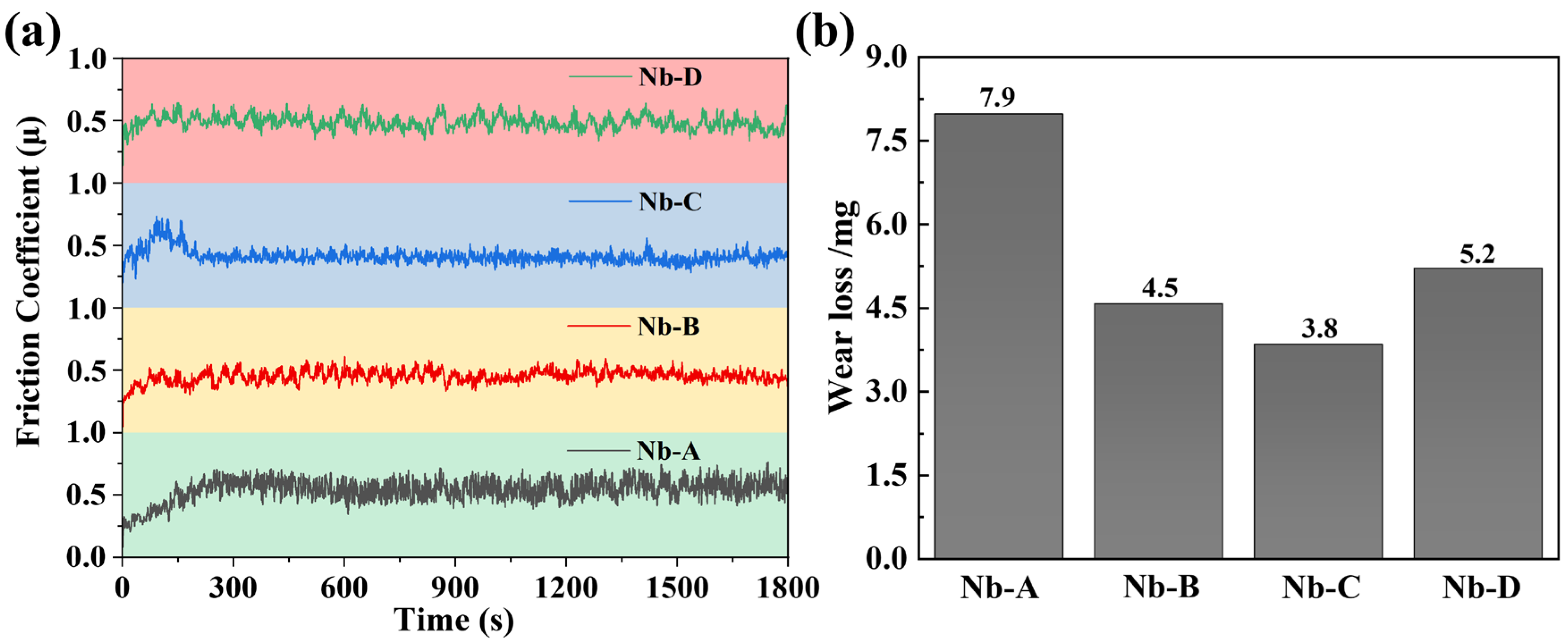
Figure 10 presents the tribological performance of laser-clad Fe-based alloy coatings as a function of Nb content, quantified through friction coefficients and wear volume measurements. During the initial wear stage (100 to 150 s), all coatings exhibit pronounced fluctuations in the friction coefficient curves. These fluctuations gradually stabilize after the running-in period. The Nb-A coating demonstrates reduced hardness, leading to an elevated friction coefficient and the maximum wear volume. As the Nb content increases, a notable improvement in hardness is observed, leading to a concurrent reduction in both friction coefficient and wear volume. Among all compositions, the Nb-C coating demonstrates optimal tribological performance, with the lowest wear loss (3.8 mg) and friction coefficient (μ = 0.413), indicating superior wear resistance.
Figure 11 shows the wear track morphologies of the specimens to further elucidate the wear mechanisms. The overall morphology of each wear track is presented in Figure 11a–d, with magnified views of the wear scar pits provided in Figure 11(a1)–(d1). As indicated by the bidirectional yellow arrows in Figure 11c, the Nb-C coating exhibits the narrowest wear track, whereas the Nb-A coating shows the widest, consistent with the measured wear volume.
Further analysis indicates that the wear track of the Nb-A coating exhibits clear signs of plastic deformation features of adhesive wear, manifested as continuous tear-like patterns along the sliding direction (highlighted by the red box in Figure 11a). Abrasive wear is also evident, with groove-like features aligned parallel to the sliding direction. The relatively low hardness of the Nb-A coating facilitates crack initiation at brittle Cr23C6 carbides located along grain boundaries during wear. This leads to localized adhesion and coating spalling. The dislodged debris subsequently acts as third-body abrasives during continued sliding. The combined effects of adhesive and abrasive wear result in a large, delaminated area within the wear scar (Figure 11(a1)), which accounts for the highest wear volume among all the coatings.
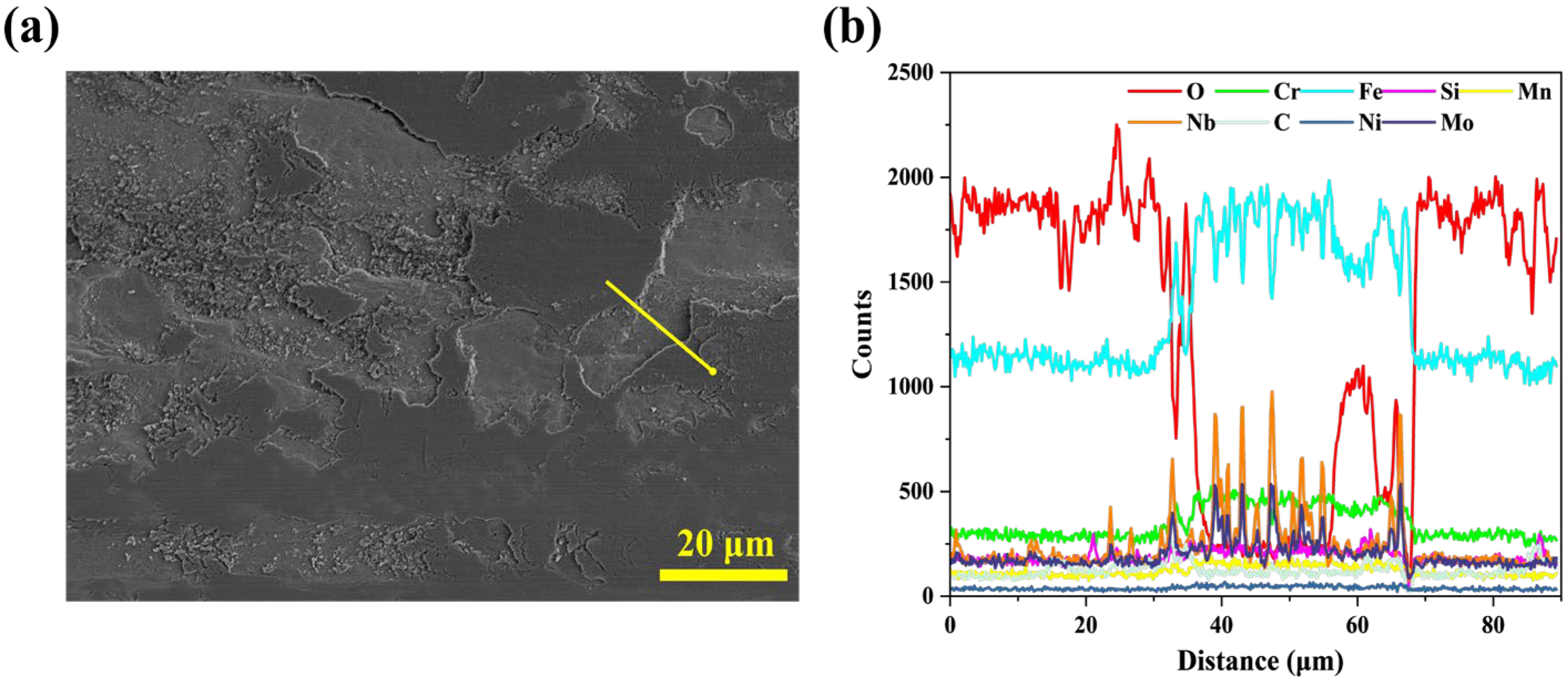
Microstructural and phase analysis of the Nb-B coating indicate a notable reduction in both the content and size of brittle Cr23C6 carbides at grain boundaries. This refinement simultaneously improves the coating’s hardness and toughness, effectively mitigating adhesive wear and resulting in a narrower wear track. The enhanced wear resistance is further supported by a substantial decrease in wear volume. EDS line scanning analysis of wear debris regions (Figure 12) confirms the occurrence of oxidation during repeated frictional contact, indicating that abrasive wear and oxidative wear are the primary wear mechanisms governing the Nb-B coating’s tribological behavior.
It is noteworthy that the Nb-C coating exhibits an increased number of NbC nucleation sites. These act not only as a nucleation core for martensite, refining the matrix structure but also significantly reduce their own particle size. As hard phases, these refined NbC particles effectively resist abrasive cutting and scratching, thereby minimizing adhesion and reducing the likelihood of carbide pull-out or fracture during wear. Consequently, only a limited number of small-scale spallation pits are evident in the wear track depressions illustrated in Figure 11(c1), with no significant tearing and minimal abrasive residue. This suppression of adhesive wear significantly contributes to a marked improvement in the coating’s wear resistance, allowing the Nb-C coating to achieve the lowest wear volume among the tested samples.
In contrast, the Nb-D coating contains coarse NbC precipitates that extend from grain boundaries into the matrix, creating a stress-concentration network. When these large particles detach, they become embedded abrasive debris that further exacerbates wear. This leads to intensified adhesive and abrasive wear, resulting in greater overall wear loss.

4. Conclusions

This study systematically investigates the influence of Nb content on the microstructure, hardness, and tribological performance of in situ NbC-reinforced Fe–Cr–Nb–C alloy coatings fabricated via coaxial powder feeding laser cladding on high-carbon forged steel. The key findings underscore the critical role of NbC morphology and distribution in determining the coating properties, providing valuable insights for designing high-performance wear-resistant coatings.
With intermediate Nb additions (2.5–3.5 wt%), the coexistence of NbC and Cr23C6 at grain boundaries was observed. The formation of semi-coherent interfaces between NbC and the martensitic matrix enhances interfacial bonding and facilitates grain refinement. The increased Nb content effectively suppresses the formation of brittle Cr23C6 carbides, promotes Cr dissolution into the (Fe,Cr) solid solution, and inhibits intergranular cracking. Consequently, the coating hardness increases significantly from 435 HV to 617 HV, and the friction coefficient decreases from 0.54 to 0.45, demonstrating a concurrent improvement in both mechanical and tribological properties.
At the optimal Nb content of 4.5 wt%, the microstructure is dominated by nanoscale rod-like NbC precipitates, which act as effective heterogeneous nucleation sites for martensite, leading to substantial matrix refinement. The near-complete elimination of Cr23C6 and the uniform dispersion of fine NbC particles result in the narrowest wear tracks, minimal adhesive/abrasive damage, and the highest wear resistance among all compositions.
However, excessive Nb addition (5.5 wt%) leads to the aggregation of coarse micron-sized NbC particles, carbon depletion in the matrix, and the formation of stress concentration sites. These factors contribute to a reduction in hardness and promote severe adhesive and abrasive wear, culminating in increased wear volume and compromised coating performance.
This work not only elucidates the underlying mechanisms through which Nb content regulates carbide morphology and distribution but also demonstrates a practical pathway for enhancing the wear resistance of laser-clad Fe-based coatings. The findings offer significant value for advancing the design of next-generation wear-resistant coatings tailored for demanding industrial applications, particularly on high-carbon steel substrates.

Author Contributions

Conceptualization, M.C. and Z.F.; methodology, X.L. and X.X.; investigation, H.Z. and L.W.; writing—original draft preparation, M.C.; writing—review and editing, X.L., Z.F., Y.J. and Y.Y.; All authors have read and agreed to the published version of the manuscript.

Funding

This research was funded by the Central Guidance for Local Science and Technology Development Fund Projects (2024ZYD0330), National Natural Science Foundation of China (NO. 52274293), Provincial directional financial transfer payment project (22ZYZF-G-02, 21ZYZF-G-01) and Chongqing Research Program of Basic Research and Frontier Technology (NO. CSTB2024NSCQ-MSX0844).

Institutional Review Board Statement

Not applicable.

Informed Consent Statement

Not applicable.

Data Availability Statement

Data are contained within the manuscript.

Conflicts of Interest

The authors declare no conflicts of interest.

References

  1. Shang, F.; Chen, S.; Zhou, L.; Jia, W.; Cui, T.; Liang, J.; Liu, C.; Wang, M. Effect of laser energy volume density on wear resistance and corrosion resistance of 30Cr15MoY alloy steel coating prepared by laser direct metal deposition. Surf. Coat. Technol. 2021, 421, 127382. [Google Scholar] [CrossRef]
  2. Chen, S.; Ni, L.; Zhang, Y.; Wang, Y.; Cui, T.; Liang, J.; Chen, J.; Wang, M. Laser cladding of a novel Fe-based coating with high wear resistance, corrosion resistance and self-lubricating properties. Surf. Coat. Technol. 2024, 478, 130468. [Google Scholar] [CrossRef]
  3. Shang, F.; Chen, J.; Song, X.; Chen, S.; Liang, J.; Wang, M. Strength-ductility and corrosion resistance match mechanism of bainite/martensite dual phase 30Cr15MoY alloy steel. Mater. Sci. Eng. A. 2022, 832, 142477. [Google Scholar] [CrossRef]
  4. Shang, F.; Chen, S.; Zhang, C.; Liang, J.; Liu, C.; Wang, M. The effect of Si and B on formability and wear resistance of preset-powder laser cladding W10V5Co4 alloy steel coating. Opt. Laser Technol. 2021, 134, 106590. [Google Scholar] [CrossRef]
  5. Hou, Q.Y.; Wang, J.T. Influence of CeO2 on the microstructure and wear resistance of iron-based alloy coating studied by Rietveld refinement method. Surf. Coat. Technol. 2010, 204, 2677–2682. [Google Scholar] [CrossRef]
  6. Gao, B.; Xu, T.; Wang, L.; Liu, Y.; Liu, J.; Zhang, Y.; Sui, Y.; Sun, W.; Chen, X.; Li, X.; et al. Achieving a superior combination of tensile properties and corrosion resistance in AISI420 martensitic stainless steel by low-temperature tempering. Corros. Sci. 2023, 225, 111551. [Google Scholar] [CrossRef]
  7. Du, A.; Lattanzi, L.; Jarfors, A.E.W.; Zheng, J.; Wang, K.; Yu, G. Role of matrix alloy, reinforcement size and fraction in the sliding wear behaviour of Al-SiCp MMCs against brake pad material. Wear 2023, 530-531, 204969. [Google Scholar] [CrossRef]
  8. Wu, H.; Zhang, S.; Zhang, H.Y.; Wang, R.; Zhang, H.F.; Zhang, C.H.; Wu, C.L.; Chen, H.T. Exploration of wear and slurry erosion mechanisms of laser clad CoCrFeNi + x (NbC) high entropy alloys composite coatings. Tribol. Int. 2024, 193, 109405. [Google Scholar] [CrossRef]
  9. Zhang, Y.; Ge, C.; Wu, Y.; Deng, Y.; Zhang, W.; Liu, X.; Liu, Y.; Chen, H. The impact of Nb on the microstructure and mechanical properties of Stellite 21 alloy coatings. Surf. Coat. Technol. 2024, 489, 131113. [Google Scholar] [CrossRef]
  10. Bolelli, G.; Colella, A.; Forlin, E.; Gehlen, L.R.; Lusvarghi, L.; Miconi, L.; Pintaude, G.; Puddu, P. Tribological performance of NbC-based hardmetal HVOF coatings with Fe-Cr-Mo matrix. Wear 2025, 564–565, 205680. [Google Scholar] [CrossRef]
  11. Pintaude, G. Strategies for the Development of Wear-Resistant Coatings: A Review. Soldag. Insp. 2021, 26, e2616. [Google Scholar] [CrossRef]
  12. Jokari, M.; Ali, Y.; Gallo, S.C.; Lin, W.; Gates, J. Effect of Cr:Fe ratio on the mechanical properties of (Cr,Fe)7C3 ternary carbides in abrasion-resistant white cast irons. J. Mater. Sci. 2023, 58, 7504–7521. [Google Scholar] [CrossRef]
  13. Yu, J.; Qiao, C.; Zhang, S.; Liu, Z.; Wróblewski, P. Tribological properties of laser-cladded Fe-based amorphous composite coatings under dry and lubricated sliding. Opt. Laser Technol. 2023, 166, 109583. [Google Scholar] [CrossRef]
  14. Zhu, C.; Fordyce, I.; Sun, S.D.; Annasamy, M.; Fabijanic, D.; Short, K.; Paradowska, A.; Leary, M.; Brandt, M.; Easton, M. Effect of Ti and TiC additions on the microstructure and wear resistance of high chromium white irons produced by laser directed energy deposition. Wear 2022, 510–511, 204519. [Google Scholar] [CrossRef]
  15. Li, J.; Zhu, Z.; Peng, Y.; Shen, G. A comparative study on microstructure evolution and wear resistance of different-sized tungsten carbide modified Fe-based laser cladding coatings. Opt. Laser Technol. 2022, 147, 107672. [Google Scholar] [CrossRef]
  16. Liu, L.; Lin, Y.; Peng, L.; Kang, X.; Wang, X. Progress in Microstructure Design and Control of High-Hardness Fe-Based Alloy Coatings via Laser Cladding. Coatings 2024, 14, 1351. [Google Scholar] [CrossRef]
  17. Ertugrul, O.; Enrici, T.M.; Paydas, H.; Saggionetto, E.; Boschini, F.; Mertens, A. Laser cladding of TiC reinforced 316L stainless steel composites: Feedstock powder preparation and microstructural evaluation. Powder Technol. 2020, 375, 384–396. [Google Scholar] [CrossRef]
  18. Xiao, Q.; Sun, W.L.; Yang, K.X.; Xing, X.F.; Chen, Z.H.; Zhou, H.N.; Lu, J. Wear mechanisms and micro-evaluation on WC particles investigation of WC-Fe composite coatings fabricated by laser cladding. Surf. Coat. Technol. 2021, 420, 127341. [Google Scholar] [CrossRef]
  19. Chen, L.; Yu, T.; Xu, P.; Zhang, B. In-situ NbC reinforced Fe-based coating by laser cladding: Simulation and experiment. Surf. Coat. Technol. 2021, 412, 127027. [Google Scholar] [CrossRef]
  20. Shifeng, W.; Guohua, L.; Jiawei, Z.; Kaian, L.; Shibin, Z. Preparation and Impact-Abrasive Wear Behavior of NbC-Reinforced Iron Matrix Composites. Adv. Eng. Mater. 2023, 25, 2301261. [Google Scholar] [CrossRef]
  21. Zhang, H.F.; Zhang, S.; Wu, H.; Wang, R.; Zhang, C.H.; Wu, C.L.; Chen, J.; Chen, H.T. Mechanical properties and corrosion resistance of laser cladding iron-based coatings with two types of NbC reinforcement. Surf. Coat. Technol. 2024, 479, 130558. [Google Scholar] [CrossRef]
  22. Tang, J.; Wang, K.; Fu, H. Laser Cladding In Situ Carbide-Reinforced Iron-Based Alloy Coating: A Review. Metals 2024, 14, 1419. [Google Scholar] [CrossRef]
  23. Tuominen, J.; Kiviö, J.; Balusson, C.; Raami, L.; Vihinen, J.; Peura, P. High-speed laser cladding of chromium carbide reinforced Ni-based coatings. Weld. World 2023, 67, 2175–2186. [Google Scholar] [CrossRef]
  24. Yuan, J.; Huang, Y.; Wang, L.; Jia, C.; Zhang, F.; Yang, L. Effect of the dissolution characteristic of tungsten carbide particles on microstructure and properties of Ni-WC/W2C reinforcement coating manufactured by TIG cladding. Int. J. Refract. Met. Hard Mater. 2023, 110, 106047. [Google Scholar] [CrossRef]
  25. Cao, Y.B.; Zhi, S.X.; Qi, H.B.; Zhang, Y.; Qin, C.; Yang, S.P. Evolution behavior of ex-situ NbC and properties of Fe-based laser clad coating. Opt. Laser Technol. 2020, 124, 105999. [Google Scholar] [CrossRef]
  26. Wu, C.; Ma, M.; Liu, W.; Zhong, M.; Zhang, W.; Zhang, H. Laser producing Fe-based composite coatings reinforced by in situ synthesized multiple carbide particles. Mater. Lett. 2008, 62, 3077–3080. [Google Scholar] [CrossRef]
  27. Zhang, H.; Yong, Y.; Wang, F.; Liang, Y.; Liu, L.; Liu, H.; Gao, Y. Progress on the Properties of Ceramic Phase-Reinforced High-Entropy Alloy Composite Coatings Produced via Laser Cladding. Coatings 2024, 14, 127. [Google Scholar] [CrossRef]
  28. Haoming, Y.; Dejun, K. Microstructure, Corrosive-Wear and Electrochemical Properties of TiC Reinforced Fe30 Coatings by Laser Cladding. J. Mater. Eng. Perform. 2025, 34, 7345–7355. [Google Scholar] [CrossRef]
  29. Cao, Y.B.; Zhi, S.X.; Gao, Q.; Tian, X.T.; Geng, T.; Guan, X.; Qin, C. Formation behavior of in-situ NbC in Fe-based laser cladding coatings. Mater. Charact. 2016, 119, 159–165. [Google Scholar] [CrossRef]
  30. Chen, J.; Zhou, Y.; Shi, C.; Mao, D. Microscopic Analysis and Electrochemical Behavior of Fe-Based Coating Produced by Laser Cladding. Metals 2017, 7, 435. [Google Scholar] [CrossRef]
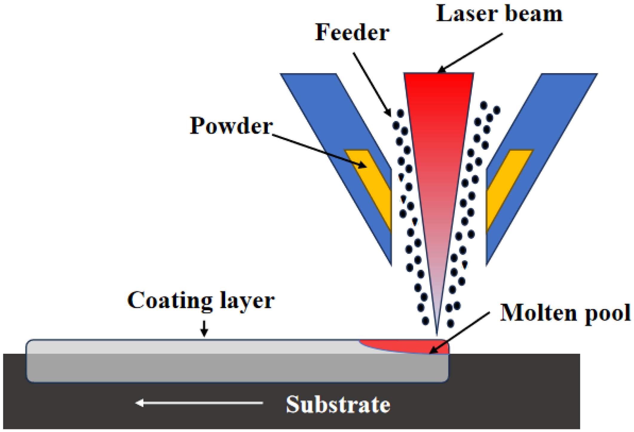
Figure 1. Schematic diagram of the laser cladding coating fabrication process.
Coatings 15 01055 g001
Figure 2. Thermodynamic calculation results of phase composition with different Nb contents. (a) Nb-A, (b) Nb-B, (c) Nb-C, (d) Nb-D.
Coatings 15 01055 g002
Figure 3. XRD spectra of coatings with different Nb contents.
Coatings 15 01055 g003
Figure 4. Cross-sectional metallographic images of coatings with different Nb contents. (a1,b1,c1,d1) show the coating cross-sections; (a2,b2,c2,d2) present magnified views of the coating regions.
Coatings 15 01055 g004
Figure 5. Microstructure of coatings with different Nb contents (a) Nb-A, (b) Nb-B, (c) Nb-C, (d) Nb-D.
Coatings 15 01055 g005
Figure 6. Magnified micrographs of coating microstructures (a) 2.5 wt% Nb, (b) 3.5 wt% Nb, (c) 4.5 wt% Nb, (d) 5.5 wt% Nb.
Coatings 15 01055 g006
Figure 7. TEM-EDS mapping of the Nb-B coating.
Coatings 15 01055 g007
Figure 8. (a) Crystal structure of NbC precipitates and lattice misfit at interfaces with grain boundary Cr23C6 and martensite matrix; (b−f) Magnified HRTEM view of region I to V.
Coatings 15 01055 g008
Figure 9. Microhardness profile of the coating microstructure.
Coatings 15 01055 g009
Figure 10. (a) Friction coefficient curves and (b) wear loss of coatings with different Nb contents.
Coatings 15 01055 g010
Figure 11. Wear track morphology of coatings with varying Nb contents. (a) Nb-A, (b) Nb-B, (c) Nb-C, (d) Nb-D; (a1), (b1), (c1), and (d1) are the magnified wear scar morphology of (a), (b), (c), and (d), respectively.
Coatings 15 01055 g011
Figure 12. EDS line scanning analysis of wear track on Nb-B coating. (a) SEM micrograph of the wear track with the line scan position, (b) corresponding elemental distribution profiles obtained from the EDS line scan.
Coatings 15 01055 g012
Table 1. Designed composition of the powder (wt%).
SampleFeCrNbMoCSiMn
Nb-ABalance9.553.001.391.010.772.33
Nb-BBalance9.554.001.391.010.722.33
Nb-CBalance9.555.001.391.010.662.33
Nb-DBalance9.556.001.391.020.612.33
Table 2. Energy Dispersive Spectroscopy point analysis results of sample locations (wt%).
PositionContent of Components(wt%)
NbMnMoFeCrC
a151.730020.718.6418.92
a20.840046.839.9312.43
a300050.3835.2714.35
a42.280074.9711.5711.18
a501.620.6885.635.846.23
a601.640.6485.635.946.06
a701.620.6985566.245.89
a843.680031.656.7317.94
a901.630.7285.706.725.23
Table 3. Planar misfit between NbC and α’-Fe.
Interface[101]NbC || [001]α’-Fe[010]NbC || [010]α’-;Fe[111]NbC || [011]α’-Fe
dα’-Fe/nm2.872.874.05
dNbC/nm3.322.354.07
cos θ 110.986
δ%15.618.10.98
Total δ% δ 011 NbC 001 α ߣ - Fe 11.56 %
Table 4. Planar misfit between NbC and Cr23C6.
Interface[101]NbC || [110]Cr23C6[010]NbC || [100]Cr23C6[111]NbC || [111]Cr23C6
dα’-Fe/nm7.555.349.25
dNbC/nm6.634.698.12
cos θ 111
δ%12.1912.1712.21
Total δ% δ 011 NbC 001 Cr 223 C 6 12.19 %
Disclaimer/Publisher’s Note: The statements, opinions and data contained in all publications are solely those of the individual author(s) and contributor(s) and not of MDPI and/or the editor(s). MDPI and/or the editor(s) disclaim responsibility for any injury to people or property resulting from any ideas, methods, instructions or products referred to in the content.