1. Introduction
During winter, while the formation of ice creates beautiful landscapes, its accumulation on critical surfaces in transportation infrastructure, such as aircraft wings, wind turbine blades, and vehicle components, presents significant operational challenges. Icing can disrupt aerodynamics, impair visibility, and lead to increased energy consumption, resulting in annual economic losses in the transportation sector that exceed billions of dollars [
1,
2]. For example, ice accumulation on aircraft surfaces can reduce lift by 30% and increase drag by 40%, which poses serious risks to flight safety [
3]. Similarly, frozen wind turbine blades can decrease power generation efficiency by as much as 50% [
4]. Traditional de-icing methods, including mechanical scraping, electrothermal heating, and chemical agents, tend to be energy-intensive, environmentally damaging, or costly, which has led to a growing demand for more sustainable anti-icing strategies [
5,
6,
7].
To mitigate the dangers posed by ice accumulation, modern ice protection methods are primarily divided into two categories: active de-icing and passive anti-icing strategies. Traditional active techniques, which include electrothermal systems, mechanical removal methods, and the application of chemical de-icers, often come with significant operational drawbacks, such as high energy consumption, inefficiency, and environmental pollution [
8]. In contrast, passive anti-icing strategies utilize the natural properties of surfaces to prevent the formation and buildup of ice without the need for additional energy sources. These methods offer environmentally friendly alternatives and have sparked significant interest in research [
9]. The passive systems manifest in diverse functional architectures based on distinct ice suppression mechanisms: hydrophobic interventions (exemplified by superhydrophobic surfaces leveraging Cassie-state air pockets [
10]), compliant interfaces (featuring low-elastic-modulus substrates that promote ice detachment) [
11], interfacial hydration barriers (implemented through polyelectrolyte brush grafting) [
12], slippery coatings (including organic-lubricant-infused systems [
13] and water-retaining hydrophilic interfaces [
14]), and fracture-assisted topographies (exemplified by low-toughness engineered surfaces [
15]). Superhydrophobic surfaces (SHSs), which draw inspiration from the “lotus effect,” are designed to delay ice nucleation by significantly reducing the contact between water and the surface, achieving contact angles greater than 150°. However, their effectiveness diminishes under extreme cold or high humidity conditions, as ice can become interlocked with the micro-structures of the surface [
16,
17,
18]. To tackle this issue, the integration of photothermal conversion materials, including carbon nanotubes (CNTs) and polytetrafluoroethylene (PTFE), with SHSs has shown great potential. These photothermal materials are capable of converting solar and infrared light into heat, which actively facilitates the melting of ice. Meanwhile, SHSs contribute by passively minimizing water adhesion, thereby enhancing the overall effectiveness of the system in managing ice formation [
1,
19,
20,
21]. Recent studies have highlighted that surface-functionalized fillers like CNTs can be uniformly dispersed in PDMS matrices through strategies like surface grafting with long alkyl chains, which not only improves interfacial compatibility but also enhances photothermal efficiency and mechanical durability, addressing the common issue of CNT aggregation in polymer matrices [
22]. The prepared CNT-induced superhydrophobic and photothermal coating demonstrates remarkable superhydrophobicity, achieving a contact angle of 154.3°. This innovative coating significantly extends the delay-freezing time to 440 s at 20 °C, which is a notable 73 times longer than that of a bare aluminum plate [
23]. Additionally, polyurethanes modified with polyethylene glycol (PEG) and polydimethylsiloxane (PDMS) effectively reduce ice shear strength to below 50 kPa [
2].
Recent advances have revealed the synergistic effects of innovative materials in combating ice formation. For instance, photothermal superhydrophobic iron foam coatings can achieve a remarkable surface temperature of 55.8 °C when exposed to sunlight, effectively melting ice in just 251 s [
4]. Additionally, polyurea coatings featuring dynamic crosslinked networks have been shown to extend the delay of freezing to a notable 331 s [
5]. These systems utilize the high photothermal efficiency of carbon-based materials, such as the delocalized π-electrons found in CNTs, alongside low-surface-energy polymers like PDMS. This combination effectively balances icephobicity with thermal conversion, enhancing the performance of these coatings in icy conditions [
24,
25,
26,
27]. Interface engineering of such fillers, including chemical functionalization (e.g., silanization, phosphorylation) and nano-structuring (e.g., core–shell architectures), has been demonstrated to further optimize dispersion, stress transfer, and interfacial bonding, thereby addressing key challenges like mechanical instability under abrasion and inadequate thermal distribution in composite systems [
28]. However, challenges remain, including (1) the mechanical instability of nano-structures under abrasion [
29], (2) the limited durability of lubricant-infused surfaces [
30], and (3) inadequate thermal distribution in composite systems [
31].
Here, we present a highly effective anti-icing coating that combines CNTs and carbon powders within a PDMS matrix applied to an aluminum substrate. This innovative design leverages the high photothermal efficiency of CNTs, the cost-effective light absorption properties of carbon powders, the low surface energy of PDMS, and the high-performing thermal conductivity of aluminum. Unlike previous research that focused on single carbon materials or utilized brittle substrates, our composite demonstrates improved mechanical resilience and durability. The objective of this work is to evaluate key characteristics, such as surface wettability (including contact angle and sliding angle), anti-icing performance (measured through freezing delay and ice adhesion), and overall durability. The findings aim to provide valuable insights for enhancing transportation infrastructure in cold climates.
2. Materials and Methods
2.1. Materials and Reagents
Carbon nanotubes with a diameter of 30–50 nm and a purity of at least 95%, as well as carbon powder with a purity of 99.5% and a size of 30 nm, were sourced from Shanghai Macklin Biochemical Technology Co., Ltd. (Shanghai, China). Anhydrous ethanol, with a purity of 99.7%, and acetone were obtained from Nanjing Kaiyan Environmental Protection Co., Ltd. (Nanjing, China). The nanomaterial dispersant was supplied by the China Building Materials Academy (Beijing, China). Epoxy resin (E51) and its corresponding curing agent were purchased from Langfang Jiutai Anticorrosion Materials Co., Ltd. (Hebei, China). and Shandong Lixing New Materials Technology Co., Ltd. (Linyi, China)., respectively. Additionally, PDMS was acquired from Shanghai Aladdin Biochemical Technology Co., Ltd. (Shanghai, China), while aluminum sheets measuring 10 mm × 10 mm × 1 mm were sourced from Shenzhen Ruihe Metal Co., Ltd. (Shenzhen, China). All reagents used in this study were of analytical grade.
2.2. Preparation of Aluminum-Based Surface Modified with Composite Coating
The aluminum substrates were subjected to a series of abrasive treatments using sandpapers of grits 400#, 800#, and 2000# to achieve a consistent surface texture. Following this, the specimens were degreased through three consecutive 5 min ultrasonic cleanses, alternating between acetone and anhydrous ethanol, and then rinsed with deionized water for 30 min before being dried convectively at 70 °C. For the solution formulation, 1 g of PDMS oligomer (Part A) was mixed with 10 mL of absolute ethanol using vortex mixing at 2500 rpm. Hybrid carbon fillers, which included multi-walled carbon nanotubes (MWCNTs) and carbon nanopowder, were added to this solution at a total loading of 0.04 g, with the specific compositional ratios outlined in
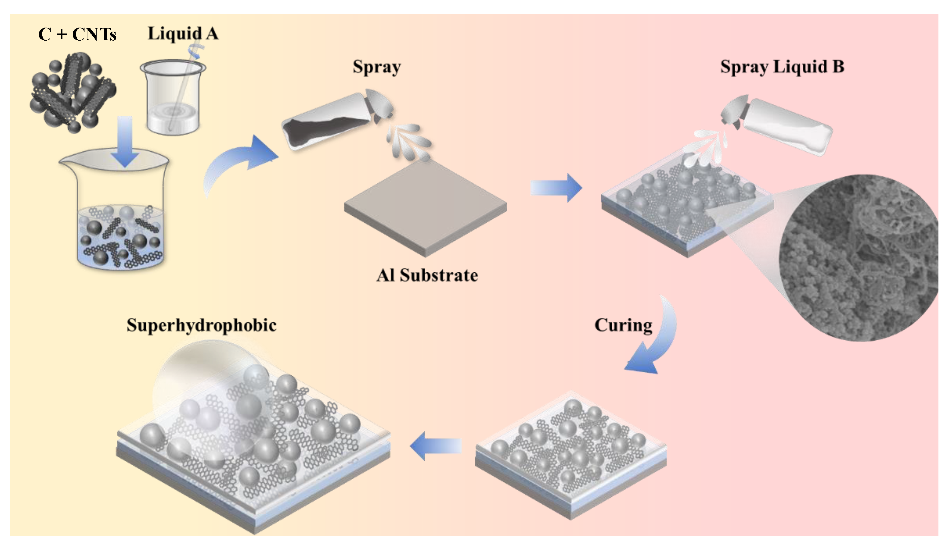
Table 1. Simultaneously, 0.1 g of PDMS crosslinker (Part B) was dissolved in 10 mL of ethanol. Both solutions were subjected to ultrasonic processing for 60 min at 100 W, followed by magnetic agitation for another 60 min at 500 rpm and 25 °C. The deposition process utilized an air-driven spray system with a nozzle diameter of 0.3 mm, maintaining a distance of 15 cm between the substrate and the nozzle. Three alternating spray passes were applied for each solution, using 3 s bursts at a pressure of 0.7 bar, with 10 min curing intervals at 70 °C between passes to facilitate solvent evaporation and precursor consolidation. The specific process is illustrated in
Figure 1.
2.3. Basic Surface Characterization
The analysis of surface functional groups was conducted using Fourier-transform infrared spectroscopy (FTIR; Cary 610/670,Varian, Inc. Palo Alto, CA, USA), which operated at a resolution of 4 cm−1 and involved 128 scans across a range of 4000–800 cm−1. For micromorphological evaluation, field-emission scanning electron microscopy (FESEM; Hitachi S-4800II, Hitachi, Ltd., Tokyo, Japan) was utilized, functioning at an acceleration voltage of 5 kV.
Surface wettability was assessed by measuring the static water contact angle using an optical tensiometer (JC2000D, Shanghai Zhongchen Digital Technology Equipment Co., Ltd., Shanghai, China) with 3 μL droplets at a temperature of 25 °C. For each sample, the contact angle was measured five times, and the average value was recorded as the final result. The test specimens were securely placed on an adjustable stage, which allowed for inclination, and they were cleaned with absolute ethanol. After drying, a precisely measured 10 μL droplet of deionized water was placed onto the substrate using a microsyringe to ensure that a spherical sessile droplet formed at a consistent initial location. With the stage set to a horizontal position at 0°, the droplet was allowed to stabilize for 60 s. The inclination of the platform was then gradually increased in 0.5°increments. After each adjustment, a brief stabilization period of 10 s was observed before capturing photographs of the droplet’s behavior. This process ultimately determined the sliding angle (SA), defined as the minimum inclination at which the droplet began to move consistently.
Using a methodology similar to the previously described procedure, the testing platform was securely positioned at a 5°. A precisely measured 10 μL droplet of deionized water was then placed onto the surface of the specimen. Symmetrical contact angle measurements were taken at both the left and right edges of the droplet, with the absolute difference between these measurements being defined as contact angle hysteresis—a key indicator of the hydrophobic properties of the sample. A larger angular discrepancy indicates a higher level of hydrophobicity in the sample.
For the tensile tests of the composite coatings, we utilized a universal testing machine (INSTRON 68TM-30, INSTRON Corporation, Massachusetts, MA, USA) equipped with a high-precision sensor. After allowing the coatings to reach equilibrium swelling from water absorption, they were cut into standard dumbbell-shaped specimens, each 1 mm thick and 4 mm wide at the cross-section. To protect the coatings from damage during clamping, protective paper was wrapped around both ends of each specimen. During the experiments, the loading accuracy was set to 0.5%, and the tensile speed was consistently maintained at 30 mm/min.
2.4. Anti-Icing Performance and Mechanical Stability
The surfaces of both the composite-coating-modified samples and the pristine samples were thoroughly cleaned with absolute ethanol to remove any oily residues. A cryogenic refrigerator, which was pre-cooled for 2 h to ensure a stable temperature of −20 °C, was prepared for the experiment. Samples were either pre-chilled to match the refrigerator’s temperature or kept at room temperature and then placed horizontally on a tray inside of the refrigerator. Using a micropipette, 10 μL of deionized water was carefully added to the center of each sample’s surface. This specific volume was selected to allow for a clear freezing process while reducing potential experimental errors that could arise from using too much water. At the same time, a timer was initiated to track the elapsed time. The state of the water droplet was continuously observed through the refrigerator’s viewing window or with the help of a camera. The freezing delay time was defined as the period from the moment the droplet made contact with the sample surface to when it completely solidified, which was indicated by the loss of liquid luster and the formation of a uniform white solid. Each sample underwent 3 tests, and the average freezing delay time was calculated to enable a comparative analysis across the different samples.
Samples underwent controlled wear testing under ambient conditions (25 °C) using a 1000-grit SiC abrasive paper mounted on a rigid substrate. Specimens were positioned coating side down to ensure full interfacial contact, with a 10 g normal load uniformly applied. Reciprocal linear motion was executed at 5 cm stroke length and constant traverse velocity of 5 cm/s (1 Hz frequency), minimizing impact forces and velocity fluctuations. Post-abrasion assessment followed predefined intervals (50 and 100 cycles), after which surfaces were ultrasonically cleaned (ethanol, 5 min). Subsequent analyses quantified residual anti-icing performance via ice adhesion measurements and characterized surface degradation through profilometry.
2.5. Electrochemical Performance
Coated working electrodes were fabricated by soldering a 0.5 mm
2 copper wire onto the surfaces of 10 × 10 × 1 mm samples. This was followed by ultrasonic cleaning in anhydrous ethanol, and the entire assembly was then encapsulated in epoxy resin. Once the resin fully cured, the surface was polished to reveal a defined working area of 10 cm
2. After freeze-drying to prepare the coated electrodes, the specimens were equilibrated by fully immersing them in simulated seawater to mimic the conditions they would face during operation. The electrochemical corrosion performance was assessed using a three-electrode cell with a Gamry Interface 1010E system. This setup included a platinum foil counter electrode measuring 10 × 10 × 0.1 mm and a saturated calomel electrode (SCE) as the reference electrode, with the specimens submerged in a 3.5 wt.% NaCl solution. Electrochemical Impedance Spectroscopy (EIS, Gamry Instruments, Inc. Warminster, PA, USA) measurements were taken over a frequency range of 10 mHz to 100 kHz, with a sinusoidal voltage variation of 10 mV. The Nyquist curves of each sample electrode were analyzed using ZView2 (ver3.1) software. Potentiodynamic polarization tests were conducted at a scan rate of 5 mV/s, ranging from −0.5 V to +0.5 V (vs. SCE). This approach allowed for the determination of corrosion potential (E
corr) and corrosion current density (i
corr) through Tafel extrapolation using Gamry Echem Analyst (ver7.8.5.8567) software. The electrochemical corrosion inhibition efficiency (IE) was calculated using Equation (1):
where
and is are the corrosion current densities of the pristine PDMS and coated samples, respectively, determined through Tafel polarization curve fitting.
3. Results and Discussion
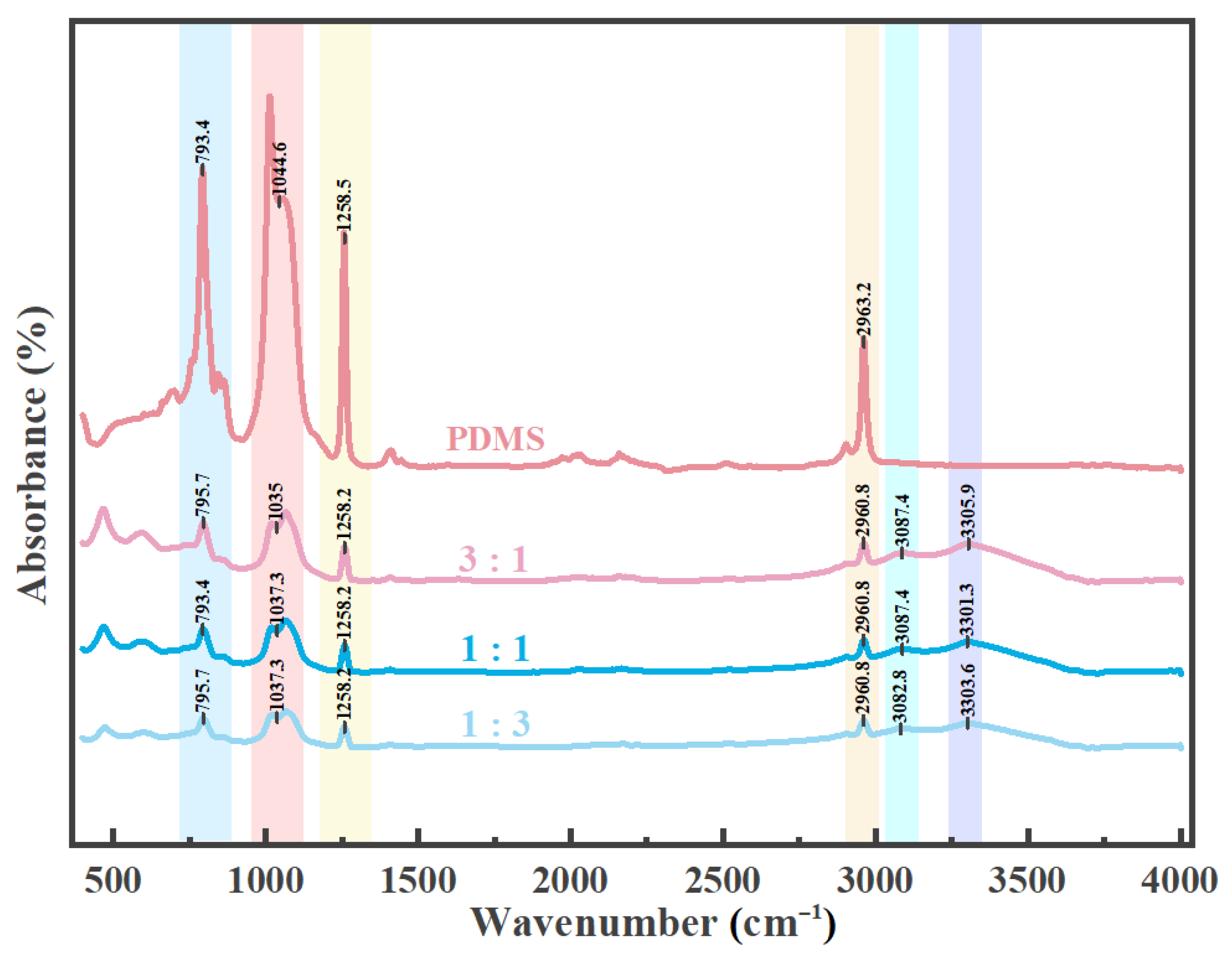
Carbon powder and carbon nanotubes were mixed into Part A of the PDMS solution, which was then reacted with Part B, the curing agent, to create an anti-icing composite coating on the surface of the aluminum substrate. Analysis of the sample surface using infrared spectroscopy (
Figure 2) revealed that PDMS displays characteristic peaks in the range of 789–796 cm
−1, corresponding to the rocking vibration of -CH
3 groups and the stretching vibration of Si-C bonds. Additionally, there are significant peaks in the range of 1020–1090 cm
−1, which overlaps with the specified range of 1020–1074 cm
−1, indicating the presence of Si-O-Si asymmetric stretching vibrations, marking its primary strong-intensity peaks [
32]. Additionally, peaks observed at 1258–1260 cm
−1 indicate the symmetric bending vibration of -CH
3 groups in Si-CH
3, whereas the range of 2950–2970 cm
−1 is associated with the asymmetric C-H stretching vibration of -CH
3 groups [
33]. Carbon nanotubes generally exhibit a C-O vibration around 1200 cm
−1 and an -OH vibration at approximately 3300 cm
−1, which can be attributed to surface functionalization or the presence of impurities [
34]. Carbon powder generally does not exhibit prominent peaks in FTIR; however, the presence of impurities or surface functional groups, such as hydroxyl or carboxyl groups, can lead to the emergence of weak absorption bands. Specifically, if these functional groups are present, -OH stretching vibrations may be detected in the range of 3000–3500 cm
−1 [
34]. The findings consistently demonstrate that all three types of composite coatings incorporate both carbon nanotubes and carbon powder.
This hybrid strategy can form a more efficient conductive and light-absorbing network. Compared with using carbon nanotubes alone, the addition of carbon powder can reduce costs while maintaining performance. During the preparation process, the inclusion of carbon powder simplifies the process’s steps, reduces the need for expensive equipment and complex operations, and thus significantly lowers the overall production cost [
35]. Meanwhile, the new surface-functionalized filler technology effectively improves the dispersibility of carbon nanotubes and carbon powder in the polydimethylsiloxane matrix, avoids agglomeration, greatly enhances the processability of the composite material, and ensures uniform distribution during the coating process, thereby giving full play to its various properties [
36].
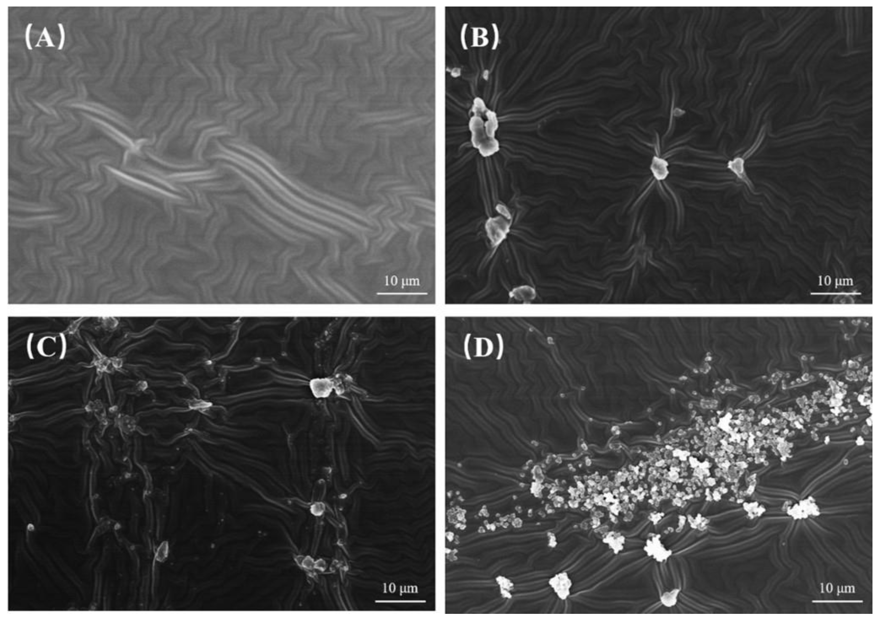
Figure 3A illustrates the surface of the pristine PDMS coating, which features a relatively smooth and uniformly wrinkled morphology free from any noticeable particulate inclusions. In contrast,
Figure 3B–D depict the surfaces of PDMS coatings that have been doped with carbon nanotubes and carbon powder in mass ratios of 3:1, 1:1, and 1:3, respectively. Specifically,
Figure 3B displays discrete, moderately sized aggregates that are distributed across the wrinkled PDMS matrix, indicating that the carbon-based fillers are partially integrated into the coating structure.
Figure 3C shows a more dispersed arrangement of the fillers, with smaller clusters and individual particles scattered across the surface, which disrupts the continuous wrinkled pattern to a greater extent than in
Figure 3B. Meanwhile,
Figure 3D reveals a significant accumulation of numerous fine particles that form dense agglomerates, extensively covering the wrinkled surface of the PDMS. This suggests that the higher proportion of carbon powder has a more pronounced effect on the morphological uniformity of the coating. Overall, the incorporation of CNTs and carbon powder into the PDMS coating leads to notable morphological changes; while the pristine PDMS surface (as seen in
Figure 3A) maintains a smooth, wrinkled texture, the surfaces of the coatings doped with CNTs and carbon powder (
Figure 3B–D) exhibit distinct particulate aggregates.
The magnified images of the P13 sample, which has a CNT to carbon powder ratio of 1:3, provide a detailed view of the sample’s surface. In
Figure 4A, the macroscopic view shows discrete agglomerates scattered across the matrix. When we look closer at
Figure 4B, these agglomerates are identified as complex structures formed by the intermingling and stacking of CNTs and nano-carbon powder. Further magnification in
Figure 4C reveals that these agglomerates consist of entangled CNTs intertwined with aggregated nano-carbon powder particles, creating a hierarchical and porous morphology. This distinctive structure suggests that the 1:3 ratio promotes significant aggregation behavior, with CNTs acting as a framework that traps and connects the nano-carbon powder. This unique micro–nano architectural arrangement could influence the surface properties and functionalities of the coating. The images of P13 highlight that these particles are clusters formed by the agglomeration of CNTs and nano-carbon powder, where the CNTs intertwine to create a framework that entrains and connects the nano-carbon powder particles, resulting in hierarchical, porous agglomerates. This cluster formation, stemming from the synergistic aggregation of CNTs and carbon powder, alters the surface topography of the PDMS-based coating, which may subsequently affect its physicochemical and functional properties.
The bar chart presented in
Figure 5 illustrates the maximum tensile stress of various samples. The pristine PDMS coating shows a maximum tensile stress of 153.60 kPa. However, when carbon nanotubes and carbon powder are added in different ratios, the mechanical properties of the samples change significantly. For instance, the sample with a 1:1 ratio of carbon nanotubes to carbon powder exhibits an increased maximum tensile stress of 174.91 kPa, indicating a reinforcing effect. Interestingly, the sample with a 3:1 ratio achieves an even higher stress level of 205.98 kPa, suggesting that this particular ratio optimally enhances the tensile properties. Furthermore, the sample with a 1:3 ratio reaches a maximum tensile stress of 210.36 kPa, demonstrating that even with a higher proportion of carbon powder, the composite coating can still exhibit high-performing tensile stress. This remarkable performance may be attributed to the synergistic interaction between carbon nanotubes and carbon powder, which helps to create a favorable load-bearing structure at the micro–nano scale [
37].
To systematically characterize surface wettability, we investigated the contact angle hysteresis, static water contact angle (CA), and sliding angle (SA) of the samples, as illustrated in
Figure 6A,B. The contact angle hysteresis, shown in
Figure 6A, is defined as the difference in contact angles between two sides of a micro-droplet measured at a tilting angle of 5° and serves as a crucial indicator for evaluating hydrophobicity, with larger values indicating better hydrophobic properties. A significant enhancement in hydrophobicity was observed with the introduction of carbon nanotubes and nano-carbon powder. Specifically, the P13 sample exhibited a rolling tilt angle of 19.9°, while the P13 sample achieved the maximum rolling tilt angle of 41.6°, demonstrating the strongest hydrophobicity. Regarding the static water contact angle and sliding angle presented in
Figure 6B, the addition of carbon nanotubes and carbon powder resulted in notable variations. The P31 surface showed a static water contact angle of 117.6° and a sliding angle of 12.8°. Furthermore, the P13 surface exhibited optimal hydrophobic performance, with a static contact angle of 139.7° and a sliding angle of 9.4°, which is consistent with the rolling tilt angle results. These collective findings suggest that carbon nanotubes and nano-carbon powder effectively regulate surface wettability to enhance hydrophobic properties, supporting the mechanism through which carbon-based nanomaterials create micro-/nano-hierarchical structures on the surface, thereby altering surface energy and wettability [
38]. The way carbon nanotubes are dispersed and arranged within the matrix plays a crucial role in the development of rough structures, which in turn affects the water-repellent properties of the coating [
39]. Such consistent trends across different evaluation indices (contact angle hysteresis, static contact angle, and sliding angle) validate the reliability of our results assessing hydrophobic performance.
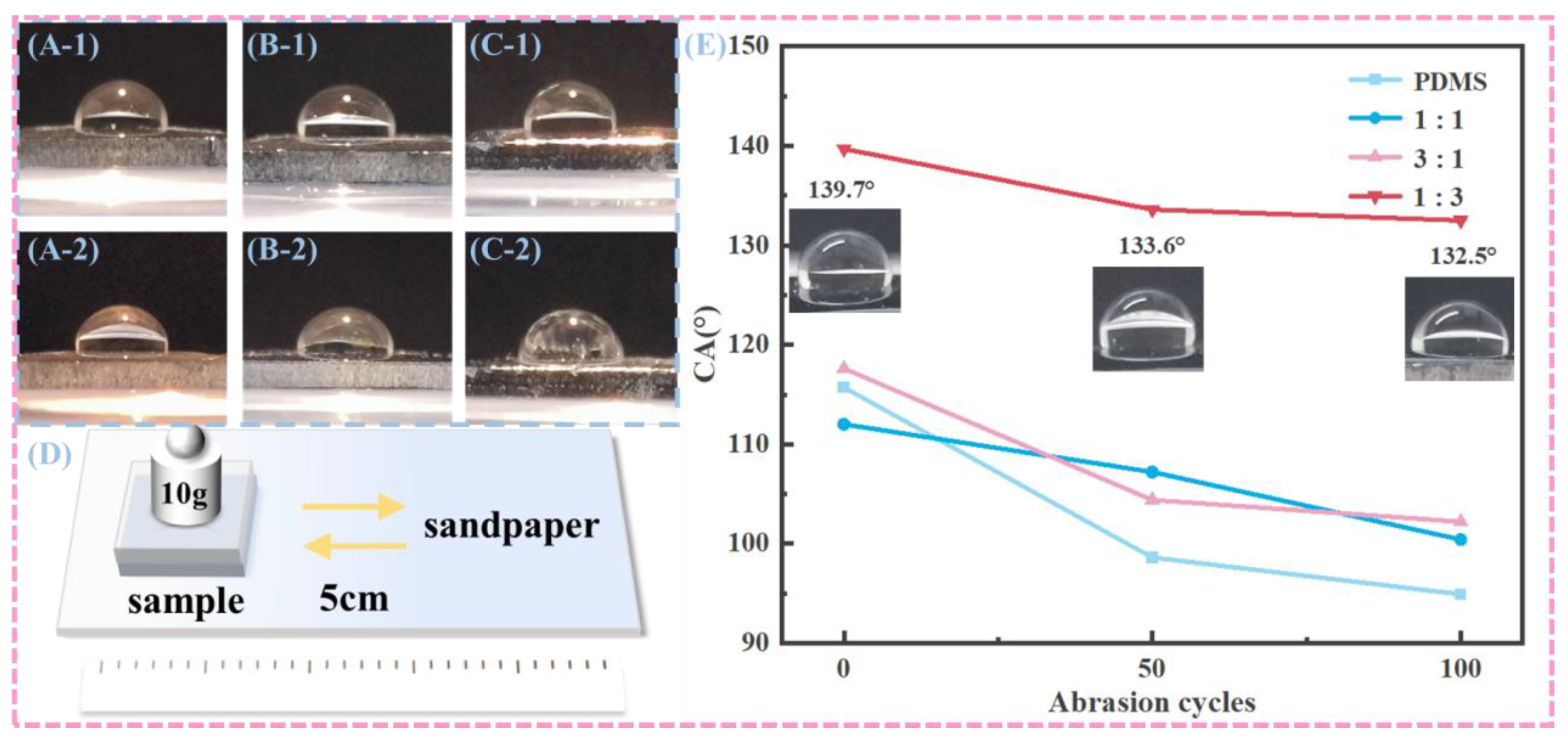
To evaluate the abrasion resistance related to wettability stability, the surface wetting properties of samples subjected to friction with sandpaper were systematically characterized, as illustrated in
Figure 7.
Figure 7D depicts the schematic of the friction test conducted between the sample surface and sandpaper, where a weight of 10g was applied over a friction distance of 5cm. The quantitative bar chart in
Figure 7E shows the contact angles of various sample surfaces after 50 and 100 abrasion cycles. Initially, the PDMS sample exhibited a contact angle of 116.3°, which decreased to approximately 95° after 100 abrasion cycles. The P11 surface started with a contact angle of about 112° and dropped to around 100° after 100 cycles. The P31 surface had an initial contact angle of 118° and reduced to about 105° following 100 cycles. The P13 surface began with a contact angle of 139.7° and decreased to approximately 132.5° after 100 cycles. These findings indicate that while the contact angles of all samples decreased with an increase in abrasion cycles, they eventually stabilized. Notably, the samples containing CNTs and nano-carbon powder generally maintained relatively higher contact angles compared to pure PDMS after abrasion, suggesting that the incorporation of these carbon-based nanomaterials can enhance the abrasion-resistance-related wettability stability of the samples to some extent. This phenomenon can be attributed to the reinforcing effect of carbon nanotubes and nano-carbon powder on the surface structure, as reported in previous studies [
28,
39,
40].
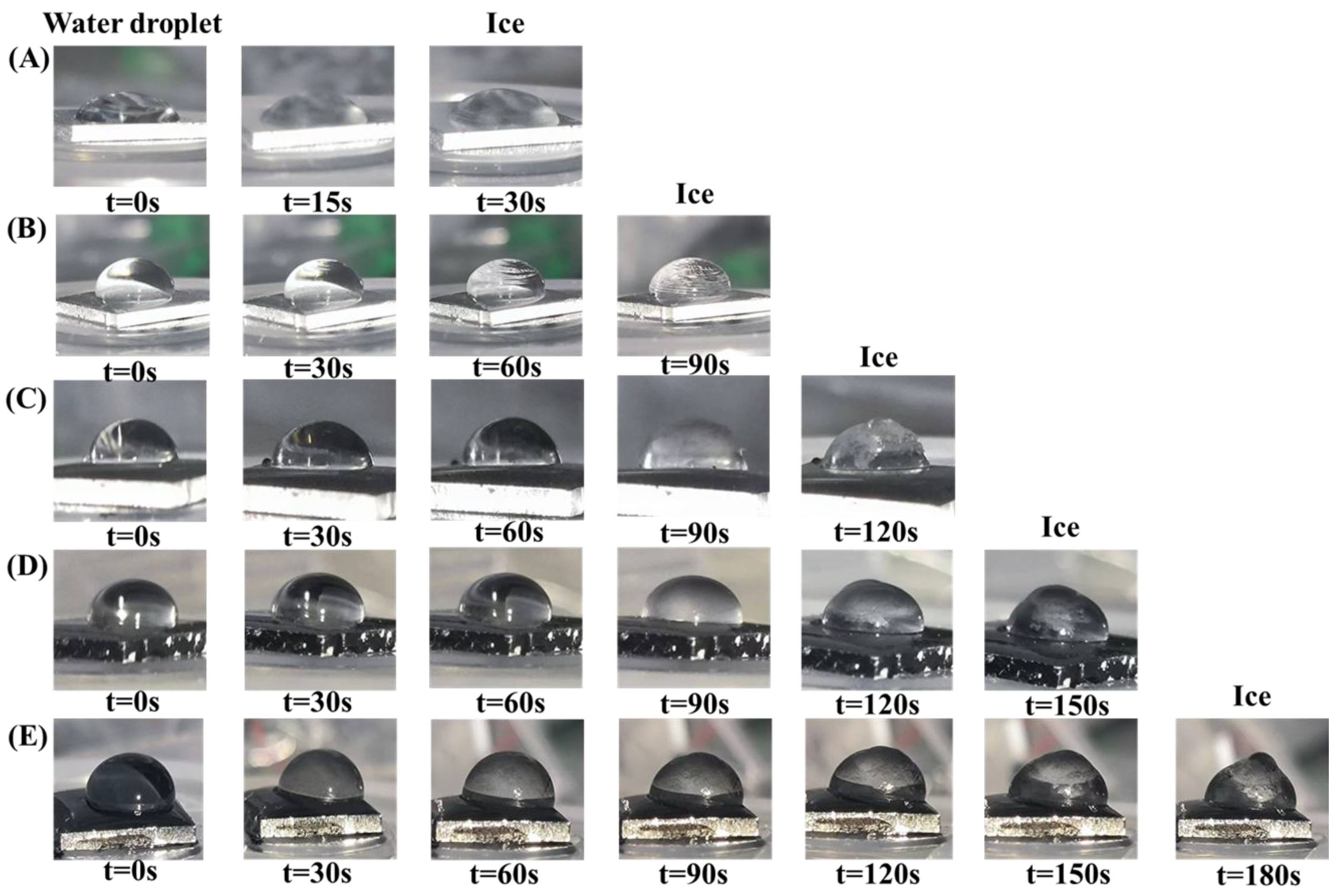
Figure 8 illustrates the ice resistance performance of various surfaces. In
Figure 8A and
Figure 9A, the ice formation process on the aluminum-based surface is depicted, while
Figure 8B–E showcase the water-freezing delay experiments conducted on PDMS coatings infused with CNTs and carbon powder in ratios of 1:1, 3:1, and 1:3, respectively. Notably, the surface with a CNT-to-carbon powder ratio of 1:3, as shown in
Figure 8E, demonstrates the most significant delay in ice formation, with the water droplet remaining in a liquid state for the longest period, lasting up to 180 s before freezing. To further expand the applicability of the findings, we supplemented tests under a −10 °C condition (detailed in
Figure S2 of the Supplementary Materials), which consistently confirmed that the 1:3 ratio sample still exhibited optimal performance, with the freezing delay extended to 240 s. Results of ice resistance tests on samples containing only carbon nanotubes or only carbon powder (detailed in
Figure S1) further indicate that the composite filling system exhibits better anti-icing performance than single filler systems. The incorporation of CNTs and carbon powder significantly prolongs the ice formation delay time, mainly due to their ability to alter the surface wettability and thermal conductivity of the PDMS coating. The entangled CNTs and aggregated carbon powder form hierarchical micro/nano structures that create a more heterogeneous surface. This increased surface complexity reduces the contact area between water and the coating, thereby hindering the process of ice nucleation; additionally, the high thermal conductivity of CNTs plays a significant role in enhancing heat dissipation, which in turn reduces the rate at which surface temperatures rise and postpones the phase transition of water into ice [
23]. This combined effect of modifying both structural and thermal properties makes the sample with a 1:3 ratio particularly effective in delaying ice formation. This observation underscores the importance of the filler proportions in optimizing anti-icing performance.
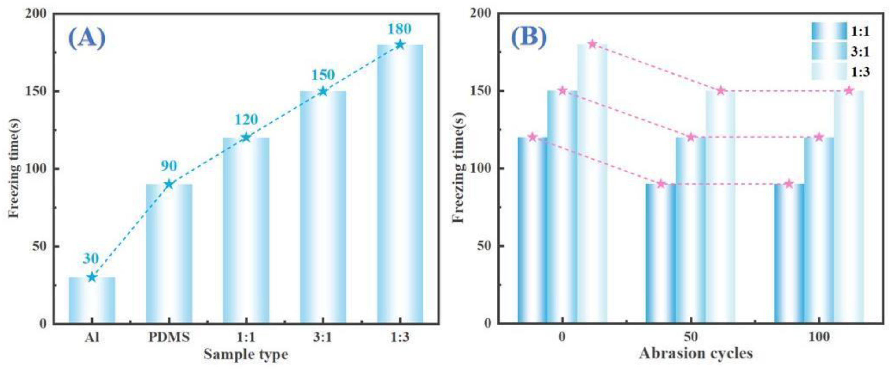
Figure 10 shows the anti-icing performance of P11, P31, and P13 surfaces following abrasion on sandpaper for 50 and 100 cycles. Specifically, (9A-1)/(9A-2), (9B-1)/(9B-2), and (9C-1)/(9C-2) correspond to the P11, P31, and P13 samples after undergoing 50 and 100 cycles of abrasion, respectively. Visual inspection indicates that abrasion leads to some degradation in anti-icing performance compared to the non-abraded state, as noted in previous studies. However, the ability to delay ice formation remains relatively stable after 50 cycles of abrasion. This stability can be attributed to the high-performing wear-resistant properties of CNTs and carbon powder, which effectively maintain the performance of the hydrophobic anti-icing surfaces [
41]. The quantitative freezing time data presented in
Figure 9B support these observations by showing the freezing times of samples with varying CNT-to-carbon powder ratios (1:1, 3:1, 1:3) after 0, 50, and 100 abrasion cycles. The findings indicate that although the freezing time decreases following abrasion, it remains relatively stable after 50 cycles. This stability underscores the critical role of carbon-based fillers in preserving the anti-icing performance of coatings even when subjected to abrasive conditions.
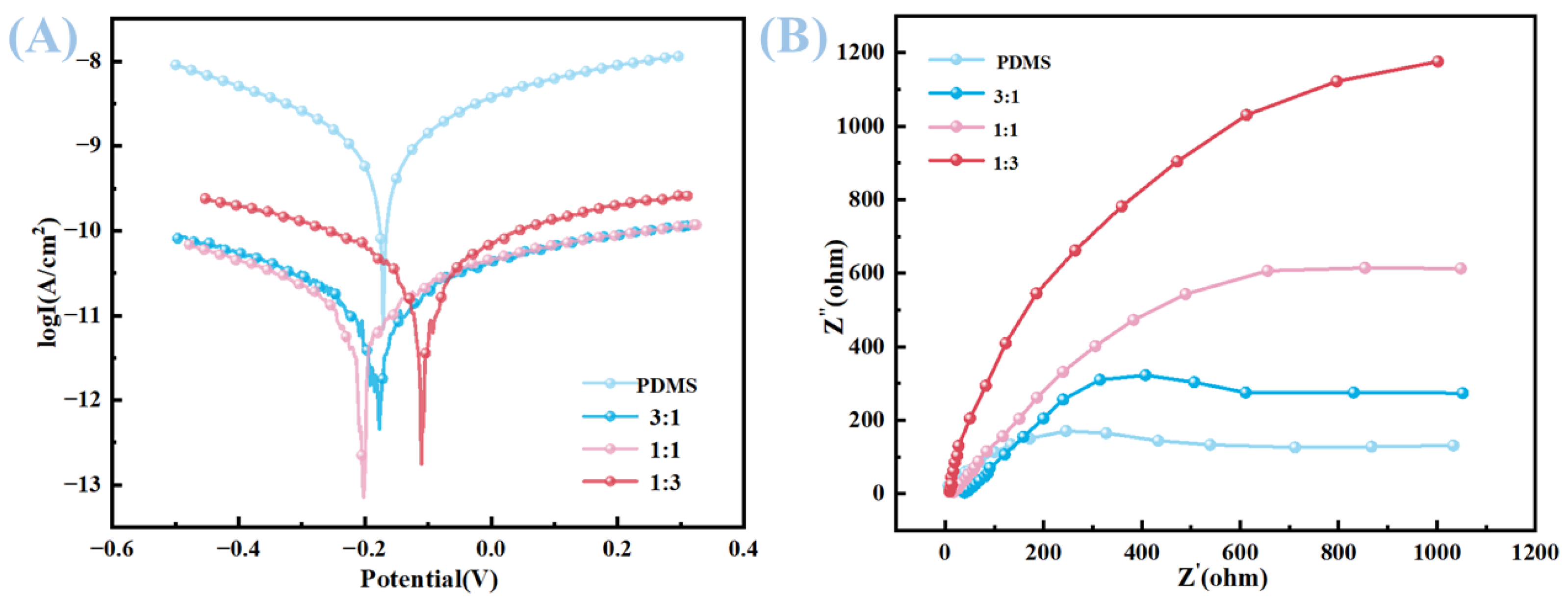
The corrosion resistance of the samples was assessed through Tafel polarization curve measurements, as illustrated in the first figure. The corrosion potential (E
corr) and corrosion current density (i
corr) obtained from curve fitting, along with the calculated corrosion inhibition efficiency (IE%), are presented in the second table. For the pure PDMS sample, the E
corr was −0.171 V, and the i
corr was 6.07 × 10
−10 μA·cm
−2. Upon the addition of carbon nanotubes and carbon powder to create various composite samples in ratios of 3:1, 1:1, and 1:3, the E
corr values shifted to −0.190 V for the 3:1 ratio, −0.200 V for the 1:1 ratio, and −0.071 V for the 1:3 ratio. Concurrently, the i
corr values showed a significant decrease, measuring 6.46 × 10
−12 μA·cm
−2 for the P31 sample, 7.63 × 10
−12 μA·cm
−2 for the P11 sample, and 2.07 × 10
−12 μA·cm
−2 for the P13 sample (
Table 2). The corresponding IE% values reached notable levels of 98.94%, 98.74%, and 99.66% for the P31, P11, and P13 samples, respectively, as calculated using Equation (1). The corrosion resistance of PDMS substrates filled with carbon powder and carbon nanotubes in different proportions was analyzed by measuring the EIS of each electrode. For the Nyquist curve, the larger the arc of the impedance arc, the higher the charge transfer resistance on the metal surface and the stronger the corrosion resistance. The Nyquist curves of the samples are shown in
Figure 11B. It can be seen that the impedance arc of the PDMS substrate without fillers is the smallest, indicating that the coating has poor compactness and poor isolation effect on the electrolyte. After adding carbon powder and carbon nanotube fillers, the impedance arc increases, and the degree of increase varies with different proportions of fillers, among which the impedance arc of the P13 coating is the largest. This enhancement in corrosion resistance is attributed to the creation of a tortuous diffusion path formed by the carbon nanotubes and carbon powder within the PDMS matrix. These nanomaterials effectively impede the ingress of corrosive ions, such as chloride ions (Cl
−), and moisture to the substrate, thereby improving the barrier properties of the coating. The carbon-based nanomaterials contribute to the formation of a dense network structure within the polymer matrix, which significantly delays the diffusion of corrosive species, ultimately leading to an overall improvement in the corrosion resistance of the composite coating [
4,
17,
20]. Such a strategy of incorporating carbon nanotubes and carbon powder proves to be effective in enhancing the corrosion resistance of PDMS-based coatings, which is of great significance for applications in corrosive environments.
4. Conclusions
This study successfully developed a multifunctional anti-icing coating by combining carbon nanotubes (CNTs), carbon powder, and polydimethylsiloxane (PDMS) on an aluminum substrate, presenting a promising approach to addressing ice accumulation issues in transportation infrastructure. The ratio of CNTs to carbon powder plays a crucial role in determining the coating’s effectiveness, with the optimized formulation, referred to as P13, exhibiting outstanding overall properties. The key conclusions of the research are summarized as follows.
(1) Morphology and hydrophobicity: Composite coatings create intricate micro/nano-structures by intertwining CNTs and aggregating carbon powder, which greatly alters the surface topography of PDMS. The P13 coating, in particular, demonstrates remarkable hydrophobic properties, with a static contact angle of 139.7° and a sliding angle of 9.4°. This exceptional hydrophobicity is due to the coating’s distinctive dense and porous agglomerates, which significantly reduce the contact area between the solid and the liquid, thereby minimizing interfacial interactions.
(2) Anti-icing performance and durability: P13 demonstrates notable anti-icing performance and durability, achieving the longest freezing delay time of 180 s at −20 °C. This is accomplished by effectively reducing the water contact area and enhancing heat dissipation, which together work to impede ice nucleation. Additionally, P13 shows remarkable mechanical stability, as evidenced by its ability to maintain a water contact angle of 132.5° after undergoing 100 abrasion cycles without any significant loss in its anti-icing capabilities, highlighting its strong wear resistance. Moreover, electrochemical analysis reveals that P13 possesses exceptional corrosion resistance, achieving a notable 99.66% corrosion inhibition efficiency. This is due to the formation of a highly tortuous barrier that effectively prevents the penetration of corrosive species, further underscoring the material’s durability and effectiveness in harsh conditions.
(3) Synergistic design and application: This composite architecture effectively utilizes the combined strengths of CNTs for their photothermal capabilities, carbon powder for its affordable broad-spectrum absorption, PDMS for its naturally low surface energy, and aluminum for its high-performing thermal conductivity. The result is a robust, high-performance coating that is well-suited for challenging anti-icing applications in cold and corrosive settings. Future research should aim to measure the photothermal effects under realistic icing scenarios, assess the long-term durability of the coating in various environmental conditions, and explore methods to scale up the production process for practical use.
