Article

Energy Sustainability, Resilience, and Climate Adaptability of Modular and Panelized Buildings with a Lightweight Envelope Integrating Active Thermal Protection. Part 1—Parametric Study and Computer Simulation

1
Department of Building Services, Faculty of Civil Engineering, Slovak University of Technology in Bratislava, Radlinského 11, 810 05 Bratislava, Slovakia
2
Faculty of Industrial Engineering, Šegova 112, 8000 Novo Mesto, Slovenia
*
Author to whom correspondence should be addressed.
Coatings 2025, 15(7), 756; https://doi.org/10.3390/coatings15070756
Submission received: 16 May 2025 / Revised: 6 June 2025 / Accepted: 16 June 2025 / Published: 25 June 2025

Abstract

Modular and prefabricated buildings are advantageous in terms of construction, transport, energy efficiency, fixed costs, and the use of environmentally friendly materials. Our research aims to analyze, evaluate, and optimize a lightweight perimeter structure with an integrated active thermal protection (ATP). We have developed a mathematical–physical model of a wall fragment, in which we have analyzed several variants through a parametric study. ATP in the energy function of a thermal barrier (TB) represents a high potential for energy savings. Cold tap water (an average temperature of +6 °C, thermal untreated) in the ATP layer of the investigated building structure increases its thermal resistance by up to 27.24%. The TB’s mean temperature can be thermally adjusted to a level comparable to the heated space (e.g., +20 °C). For the fragment under consideration, optimizing the axial distance between the pipes (in the ATP layer) and the insulation thickness (using computer simulation) reveals that a pipe distance of 150 mm and an insulation thickness of 100 mm are the most suitable. ATP has significant potential in the design of sustainable, resilient, and climate-adaptive buildings, thereby meeting the UN SDGs, in particular the Sustainable Development Goal 7 ‘Affordable and Clean Energy’ and the Goal 13 ‘Climate Action’.

1. Introduction

Directive (EU) 2024/1275 [1] of the European Parliament and the Council, dated 24 April 2024, sets several ambitious targets for reducing the energy performance of buildings, which will have a lasting impact on long-term energy consumption. New and substantially renovated existing buildings are to meet minimum energy performance requirements adapted to local climatic conditions, taking into account their impact on long-term energy consumption. The potential of alternative energy supply systems has not yet been fully explored; therefore, it is first necessary to ensure that energy requirements for heating and cooling are reduced to a cost-optimal level. These requirements apply to both new and renovated buildings, irrespective of their size.
In 2015, the United Nations (UN) established seventeen Sustainable Development Goals (SDGs), outlined in the official document Transforming Our World: The 2030 Agenda for Sustainable Development [2]. To meet all the goals set out in the 2030 agenda, all sectors must collaborate to find standard solutions to global challenges. Our research has a long-term focus on Goal 7 “affordable and clean energy” and Goal 13 “climate protection”.
The present work focuses on the research area of active thermal protection (ATP), i.e., combined building–energy systems, in the energy function of the thermal barrier (TB). A thermal barrier is defined as an active element in a building structure that can be used to control the passage of heat through the external building structure (eliminating heat loss or heat gain), thereby allowing the building to adapt to sudden or prolonged changes in climate flexibly. The physical principle of TB is predicated on dynamic thermal resistance, which is defined as a controlled and regulated temperature change between the static load-bearing structure and the external thermal insulation layer. This area of research has been investigated in our department for over two decades, by Prof. Ing. Daniel Kalús, PhD, who is the author of three national utility models and one European patent [3,4,5,6]. The most significant outcomes of our analyses, parametric studies, and experimental measurements have been published in scientific articles [7,8,9,10,11,12,13].
The utilization of advanced technical solutions for implementing active thermal protection in buildings has garnered increasing interest, primarily due to the significant potential for enhancing the energy sustainability, resilience, and adaptability of buildings to climate change, as well as the imperative for decarbonisation in the building sector. These solutions offer optimal strategies for achieving a balance between energy consumption and thermal comfort of the built environment. An overview of the most important works is given in Section 2.1. However, there is a paucity of analysis on the thermal barrier (TB) integrated into the lightweight envelope of modular and panelized buildings using a low-temperature heat transfer fluid, e.g., cold water from a well or public water supply.
This study aims to analyze the potential of thermal barriers in terms of energy savings through a parametric study during the heating and cooling seasons (as specified in this document). It has been found that the implementation of active thermal protection (ATP) has the potential to reduce the thickness of thermal insulation, so we focused on optimizing the axial distance of the pipes and the thickness of the thermal insulation through computer simulation for a specific type of wall construction.
The innovation of our research is based on the analysis of the energy potential of cold water from a well or public water supply without any heat treatment introduced into the ATP layer of the building structure under investigation in the TB function, where assuming an average heat transfer medium temperature of only +6 °C, its thermal resistance is theoretically increased by up to 27.24%. However, it is recognized that the energy function of TB has significantly higher potential, given that the average temperature of the heat transfer medium can be thermally treated to a level comparable to that of a heated space, for example +20 °C. For this purpose, a reversible heat transfer medium from the heating system is used as waste heat and/or any renewable energy source (RES). As a result, heat losses through the building envelope are negligible. TB is also very important for cooling, as the average heat transfer medium temperature of +20 °C can only be achieved with cold water, which can be heated by waste heat from the building’s energy systems and RES. We assume that preheating of domestic hot water (DHW) and cooling of the façade, using external active thermal protection (ATP) located under the outer surface of the façade, has a more significant impact on passive cooling than TB between the load-bearing and thermal insulation layers of the building envelope.
The utilization of cold water without undergoing any thermal treatment serves to enhance the thermal resistance of a building structure in a straightforward yet effective manner. This approach aligns with the philosophical tenet that Leonardo da Vinci expressed, “Simplicity is the ultimate sophistication”.
The ATP system actively controls the heat transfer through the building structure, enabling buildings to be energy-sustainable, resilient, and able to respond flexibly to climate change, thereby meeting the UN Sustainable Development Goals, particularly Sustainable Development Goal 7, “Affordable and clean energy”, and Goal 13, “Climate Action”.

2. Materials and Methods

The optimal calculation, design, and assessment of modular and panelized buildings with a lightweight envelope integrating active thermal protection must bridge the differences between research, development, design, and actual implementation. In the first part of Section 2.1, we provide an overview of scientific and professional papers. In Section 2.2, we demonstrate the analysis strategy, validation methods, and optimization of ATP in a lightweight building envelope through a parametric study and computer simulation.

2.1. Overview of Scientific and Professional Studies

An overview of scientific and technical publications with a clear link to energy use in buildings with combined construction and energy systems provides information on research, innovations in active thermal protection, computer simulations, optimal use of energy sources, analysis and optimization of energy processes, multi-energy systems, pollution mitigation strategies through sustainable, safe, and efficient building energy systems, climate resilience and adaptability of buildings, and a fair and effective transition to a zero-energy future.
The overview of scientific and professional work was divided into research areas, including publications on active thermal protection, dynamic thermal resistance, dynamic thermal insulation, energy savings using thermal barriers, and applications with phase change materials (PCM), as well as computer simulations of energy phenomena in buildings.

2.1.1. Research Area—Active Thermal Protection

A pioneer in the field of active thermal protection is the engineer and physicist Edmond D. Krecké, who made significant contributions to the practical application of ATP, particularly in the energy function of the thermal barrier. By harnessing the sun’s energy through solar energy roofs and storing it in ground heat storage, he developed a patented system called ISOMAX, designed for residential buildings [14]. This system started to be implemented in the 1990s, and its development continues to this day. ISOMAX uses ATP in thermal insulation in three main ways: first, by placing it between the supporting structure and the thermal insulation; second, by combining the placement between the supporting structure and the insulation with the addition of ATP on the exterior side of the insulation; and third, by incorporating it into the reinforced concrete core of the building’s exterior walls, which are poured with concrete on site using special expanded polystyrene (EPS) formwork [15].
Other important scientific and professional publications in this research area include Xu X., Wang S., Wang J. and Xiao F. [16] reporting that using renewable energy sources (RES) and waste heat from low-energy sources can reduce our daily reliance on high-energy sources such as electricity, thereby reducing greenhouse gas emissions and promoting environmental protection. Active embedded pipes, typically used in floor and ceiling systems, utilize water to transfer heat or cold. The compact arrangement of the pipes has been shown to enhance heat exchange between the slab mass and the water in the duct. The heat or cold storage inherent in the design can be utilized for preheating or precooling, as well as for load shifting and taking advantage of nighttime electricity tariffs in certain regions. The paper introduces active structure technology with embedded ductwork, utilizing widely available low-energy resources. It also reviews computational heat transfer models of this structure and their practical applications in real building systems. The review demonstrates the suitability of developing active structures for practical applications where low-energy resources are advantageous.
Krzaczek M. and Kowalczuk Z. [17] present the TB technique, an indirect heating and cooling technique for residential buildings driven by solar thermal radiation. This consists of U-tubes placed inside external walls, with a circulating fluid of variable mass flow rate and inlet temperature. The formation of a semi-surface parallel to the wall surface, along with a spatially averaged temperature close to the reference temperature of 17 °C throughout the year, is key. The TB technique stabilizes and reduces the heat flux normal to the wall surface, ensuring its direction remains from the indoor air to the ambient air throughout the year. The paper’s central objective is to examine the thermal performance and stability of the TB. Utilizing ABAQUS, a three-dimensional finite element model of a prefabricated exterior wall element incorporating a TB U-tube system with fluid flow was created, with the FE analysis supported by a novel SVC control system implemented in FORTRAN to simulate realistic operating conditions. The paper also presents the advantages of the TB heating and cooling technique.
Zhang Z., Sun Z. and Duan C. [18] argue that wall heat transfer affects energy savings and indoor thermal comfort. When adjustable, it can regulate indoor temperature, reducing building energy consumption. This paper proposes the wall-implanted heat pipe (WIHP) for solar energy utilization, investigating heat transfer and energy saving. Using Jinan city’s meteorological data, the findings show a strong correlation between theory and experiments, indicating model reliability. The adjustable and controllable WIHP can reduce heating loads and enhance thermal environments. In winter, the south external wall experienced a 14.47% reduction in heat loss. This suggests that this wall type could improve the indoor thermal environment, making it a viable engineering application.
Li A., Xu X., and Sun Y. [19] propose a novel low-energy utilization system, i.e., a wall with tubes integrated with a ground heat exchanger, and investigate its energy-saving potential in five regions of China. The cold or hot water from the ground source, coupled with a heat exchanger, is fed into the pipe-integrated wall to capture the heat gains or losses. The authors developed a real-scale energy simulation platform to estimate the energy-saving potential. The study’s findings show that the system’s energy-saving potential varies by region. The building attains its maximum percentage energy savings in warm climates, followed by hot summer, cold winter, very cold, cold and hot summer, and warm winter climate regions, respectively. A multi-criteria performance evaluation concurrently determines the optimal low-energy system size in each region. The inset tube wall system can be implemented to conserve energy, with the study’s results guiding its practical applications in different regions.
In the next section, references to other necessary research in the field of combined building and energy systems, renewable energy sources (RES), and experimental measurements of research objects are provided without further description [20,21,22,23,24,25,26,27,28,29,30,31,32,33,34,35,36,37,38,39,40,41,42,43,44,45,46,47,48,49,50,51,52,53,54].

2.1.2. Research Area—Computer Simulation and Modelling of Energy Phenomena in Buildings

Yan et al. [55] report that buildings consume 30% of the world’s energy, making it crucial to reduce consumption to conserve energy and tackle climate change. Building performance simulations estimate and optimize building performance, providing reference values for assessing energy consumption and the effects of energy-saving technologies. Occupant behaviour is a key factor influencing energy consumption, including presence, movement, and interaction with building energy devices and systems. However, occupant behaviour modelling is lacking, as different energy modellers use varied data and tools, producing different and incomparable results. To address this, the International Energy Agen (IEA) Energy in Buildings and Community Programme has established a scientific methodological framework, including data collection, behaviour model representation, modelling and evaluation approaches, and the integration of behaviour modelling tools with building performance simulation programmes. Annex 66 also includes case studies and application guidelines for building design, operation, and policymaking, using interdisciplinary approaches to reduce energy use and improve comfort and productivity. This paper highlights the key research issues, methods, and outcomes of Annex 66, and outlines the future research needs.
Santos-Herrero J.M. et al. [56] state that most human activities currently pollute the atmosphere, making it vital to reduce CO2 emissions. The construction sector is a key offender, and the EU’s ‘nearly Zero Energy Building’ (nZEB) concept aims to minimize the ecological footprint and ensure energy sufficiency. More than a decade has passed since its inception, and recent advances in computer technology have made it a viable option. Research on this topic has been published in reputable journals and conferences, and a review of this research is presented here. The paper explains the nZEB concept and reviews research articles on achieving it. A research gap has been identified, so enabling concepts and technologies such as ‘Building Energy Performance Simulation’ (BEPS) and ‘Model Predictive Control’ (MPC) are discussed, and included in a specific state-of-the-art for each concept, since the academic community considers these tools should apply to building air conditioning to achieve nZEB. Following a comprehensive analysis, it is concluded that significant opportunities exist to optimize energy consumption when combining BEPS’s (for modelling and simulation) and MPC (for control strategies) properly. This can help manage a HVAC system practically using RES, reducing CO2 emissions worldwide, and achieving substantial energy savings.
Yang Y., Chen S., Zhang J., Zhang Z., Li S., Chen K., and Xiao X. [57] present thermally activated building envelopes (TABEs) as multifunctional components that combine structural and energy properties, re-examining the heat charging processes. They propose Arc-finTABE with directional heat charging features to optimize thermal barrier formation. A comprehensive, parameterized analysis based on a validated mathematical model explores five fin-structure design parameters and insulation thickness. Results verify that directional charging strengthening fins can improve Arc-finTABE’s transient thermal performances and enlarge its thermal energy accumulation area, with maximum heat loss growth of less than 3.17%. Straight main fin configurations with 30° fin angles, 0.4 shank length ratios, and no leftward fin mounting are preferred in load-reduction mode. In comparison, 150° fin angles, 0.8 shank length ratios, and multiple fin designs (especially one horizontal fin) are more favourable in auxiliary-heating mode. Branch fins should be balanced between performance improvement and material usage, with larger arc angles preferable in the load-reduction mode and smaller arc angles in the auxiliary-heating mode. The strengthened invisible thermal barrier reduces the static insulation layer by 20%–80%, achieving equivalent thermal performance to conventional high-performance walls.
Zhou S. and Razaqpur A.G. [58] propose a phase change material (PCM) Trombe wall with a novel dynamic layer to minimize heat loss and enhance thermal efficiency. When the PCM wall is charging, its face is exposed to solar irradiation while the insulation side is exposed to air. Then the walls switch positions. A large-scale model is constructed and tested. It is analyzed using CFD, which agrees with other methods. Three building units are then examined: one with the proposed wall, another with an analogous static wall, and a third with a static wall but without PCM. During discharging, temperatures are measured. Energy efficiency and thermal efficiency are analyzed. The wall with PCM is 25.3% more energy efficient and 79.8% more thermally efficient than the static wall. The wall with an analogous static wall is 17.5% more efficient. To achieve even higher efficiency, it is recommended that thermal resistance be reduced by using materials with low density and heat capacity.
Mendes V.F., Cruz A.S., Gomes A.P. and Mendes J.C. [59] explain how researchers and designers assess strategies to improve building thermal performance and energy efficiency. However, regional standards and research groups vary in their methods. These systematic reviews examine the procedures for evaluating building thermal performance through energy simulations. Articles from Scopus and Web of Science were surveyed from 2011 to 2022. A total of 158 were read in full, and the most used methods were identified. Most publications were authored by researchers in the Northern Hemisphere, but some were written by researchers in the Southern Hemisphere, notably those from Brazil. The three most used were thermal load (94%), degree-hour (or degree-day) (9%), and design days (5%). EnergyPlus is used in 65% of studies, and 62% incorporate validation or calibration. Articles are often unclear and lacking complete simulation parameters. This study introduces a checklist of best practices. The provision of a valuable framework for future assessments of building thermal performance through simulation is a key strength of the approach.
In addition to the scientific papers described in more detail, which deal with computer simulations and modelling of energy phenomena in buildings, further studies closely related to these promising research methods are recommended, particularly in the construction and building energy systems [60,61,62,63,64,65,66,67,68,69,70,71,72,73,74,75,76,77,78,79,80,81,82,83,84,85,86,87,88,89,90,91,92,93,94,95,96].

2.2. Analysis Strategy, Validation Methods, and Optimization of ATP in Lightweight Building Envelope

In terms of the analysis strategy—validation method and optimization of ATP in a lightweight building envelope—we first present the theoretical background used in the research, describe the mathematical and physical model of the envelope wall fragment, show the results of the parametric study for different variants, and finally define the input data for the computer simulation of the optimization of the axial distance of the tubes in the ATP layer and the thickness of the thermal insulation.

2.2.1. Theoretical Foundations

In this section, the fundamental calculation procedure according to STN 73 0540-2+Z1+Z2:2019 [97] is delineated, on the basis of which a mathematical–physical model related to the present research was created. An illustration of this model, accompanied by an explanatory note, is provided in Section 2.2.2 below.
The calculation, design, parametric study, computer simulation, and subsequent analysis of modular and prefabricated buildings with lightweight envelopes integrating ATP, are based on the boundary conditions of location, external and internal design temperature, building structure composition, thermal resistances R ((m2·K)/W) and heat transfer coefficients U (W/(m2·K)) of the individual materials. The fundamental theoretical assumption is the calculation of the temperature evolution in the considered building structure according to STN 73 0540-2+Z1+Z2:2019.
To calculate the thermal resistance (1) of the j-th structure, it is necessary to use the following formula:
R j = d j λ j
Here Ri is the thermal resistance of the j-th layer of the structure ((m2·K)/W), dj is the thickness of the j-th layer of the structure (m), and λj is the coefficient of thermal conductivity of the j-th layer of the structure (W/(m·K)).
To calculate the thermal resistance of a multilayer structure, the formula from should be used:
Rc = ∑ Ri
R = Rsi + Rc + Rse
Here R is the thermal resistance of the structure ((m2·K)/W), Rc is the total thermal resistance of the structure ((m2·K)/W), Rj is the thermal resistance of the j-th layer of the structure ((m2·K)/W), Rsi is the thermal resistance to heat transfer at the internal surface of the structure ((m2·K)/W), and Rse is the thermal resistance to heat transfer at the external surface of the structure ((m2·K)/W).
The static transmission heat loss coefficient of a multilayer structure can be written as:
U = 1 R s i + R c + R s e
Here U is the static transmission heat loss coefficient (W/(m2·K)/), Rc is the total thermal resistance of the structure ((m2·K)/W), Rsi is the thermal resistance to heat transfer at the internal surface of the structure ((m2·K)/W), and Rse is the thermal resistance to heat transfer at the external surface of the structure ((m2·K)/W).
The temperature in the j-th layer of the structure is given as:
θj = θiU × (θiθe) × (Rsi + ∑Rj)
Here U is the static transmission heat loss coefficient of the structure (W/(m2·K)), Rsi is the thermal resistance to heat transfer at the internal surface of the structure ((m2·K)/W), ∑Rj is the sum of thermal resistances of the j-th layers of the structure ((m2·K)/W), θe is the outdoor design temperature in winter (°C), θi is the indoor design temperature (°C), and θj is the temperature in the j-th layer of the structure (°C).
In our research, we assume a 3D prefabricated component system. The heat transfer equation for the transition conditions in Cartesian coordinates is given as [98,99,100,101,102,103]:
C p ρ T t = λ 2 T x + 2 T y + 2 T z
Here Cp is the specific heat capacity (kJ/(kg·K)), T is the temperature (°C), t is the time (s), ρ is the density of the wall layer material (kg/m3).
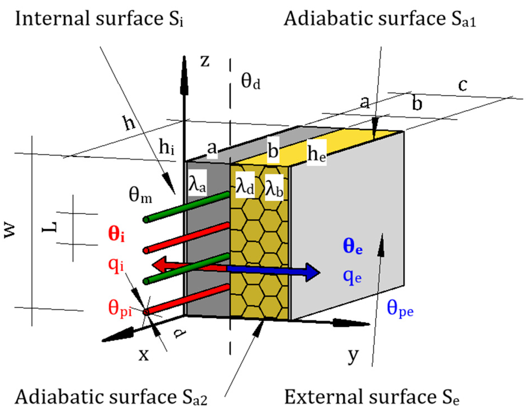
To use or calculate the heat transfer equation, it is necessary to specify the boundary conditions. In our case, the outer wall construction separates the interior spaces with space temperature Ti from the ambient conditions. That is, Newton’s law defines the boundary conditions of the Si and Se surfaces. Consequently, the heat transfer coefficient by radiation and convection, respectively, is determined by the rate of heat exchange by convection and radiation on the indoor surface Si. That is, the boundary conditions on the Si surface are determined by the formula:
λ T ( t ) x S i = h i T F i t T i
In the structure, heat is exchanged between the outdoor surface of the Se and the outdoor environment. The heat exchange is composed of convection and radiation, and these two components must be considered separately. The solar air temperature defines radiation, and the convective heat transfer coefficient determines convection. The solar air temperature Ti can be defined as the fictitious outdoor air temperature that, in the absence of radiative exchange at the exterior roof or wall surface, would provide the same rate of heat transfer through the wall or ceiling as the actual combined heat transfer mechanism between the sun, the roof or wall surface, and the outdoor air and environment. Since the ambient conditions are variable, the boundary conditions on the outdoor surface of Se can be defined as:
λ T ( t ) x S e = h e ( t ) T e t T F e ( t )
Here he(t) is the convection heat transfer coefficient at the outdoor surface (W/(m2·K)), TFe(t) is the outdoor surface temperature (°C), Te(t) is the solar air temperature (°C).
The boundary conditions on the adiabatic surfaces Sa1 and Sa2 are defined as:
q(t)|Sa1 = 0
and
q(t)|Sa2 = 0
Here q(t) is the thermal flow perpendicular to the surface (W/m2).
To calculate the heat output or heat flux density q (W/m2) from the ATP layer, it is necessary to know or determine the axial distance of the heating pipes, the thermal resistance of the surface layer of the wall, the outer diameter of the heating pipes, the method of contact of the pipes with the spreading layer (characterized by the coefficient ak), the thickness and the thermal conductivity of the wall layer in front of the heating pipes towards the interior and the exterior. The calculation is carried out according to EN 1264—Part 1 to 5. The specific thermal power can be written as:
q = B · i ( a i m i ) · Δ θ H
Here q is the specific thermal power (W/m2), B is the coefficient dependent on the system (W/(m2·K)), i ( a i m i ) is the power product combining the parameters of the construction; while:
Δ θ H = θ V θ R ln θ V θ i θ R θ i
Here, ΔθH is the average temperature of the heating fluid (°C), θV is the temperature of the supply heating fluid (°C), θR is the temperature of the return heating fluid (°C), and θi is the nominal interior temperature of the room (°C).
The standard STN EN 1264—parts 1 to 5 lists several types of construction. The design with the ATP is adequate for the standard design type B, as shown in Figure 1.
For this type of construction, the specific thermal power q is calculated according to STN EN 1264—parts 1 to 5 as:
q = B · a B · a T m T · a u m u · a W L · a k · Δ θ H
Here q is the specific thermal power (W/m2), B is the coefficient dependent on the system (W/(m2·K)), while:
a B = 1 1 + B   ·   a u   ·   a T m T   ·   a W L   ·   a K   ·   R λ , B   ·   f   ( L )
herewith:
F   ( T ) = 1 + 0.44   L
Here aB is the covering coefficient (-), aT is the pipe spacing coefficient (-), λE is the thermal conductivity of the distribution layer (W/(m·K)), su is the thickness of the distribution layer above the pipes (m), mi is the exponents for calculating the characteristic curves (mT, mu) (-), while:
m T = 1 L 0.075   valid   for   0.050   m L 0.375   m
mu = 100 (0.045 − su) valid for su ≥ 0.010 m
Here L is the spacing of the heating pipes (m), su is the thickness of the distribution layer above the pipes (m).

2.2.2. Mathematical–Physical Model of a Lightweight Building Envelope

Theoretical analyses and computer simulations of the energy functions of the ATP are based on the three-dimensional non-stationary differential heat conduction equation (see Figure 2 and Equation (18)) under Newtonian boundary conditions, i.e., heat transfer at the boundary of the structure with the outside and inside air (see Equation (19)) [89,104]. Colleagues mathematically modified these equations and boundary conditions from the Department of Mathematics at the Faculty of Civil Engineering, Slovak University of Technology in Bratislava.
The three-dimensional non-stationary differential heat conduction equation can be written as [104]:
c ( x , y , z ) ρ ( x , y , z ) θ x , y , z , t t   =   x λ x , y , z θ x , y , z , t x + +     y λ ( x , y , z ) θ x , y , z , t y +   z λ ( x , y , z ) θ x , y , z , t z
The Newtonian boundary conditions, i.e., heat transfer at the boundary of the structure with the outside and inside air [89,104] is as follows:
qj = hj (θ(x,y,z,t) − θj)
qj = −λ∇θ.n
Here c(x,y,z) is the specific heat capacity of the material (J/(kg·K)), ρ(x,y,z) is the material density (kg/m3), θ(x,y,z,t) is the temperature as a function of three spatial variables and time (°C), t is the time (s), x, y, z are the spatial coordinates, λ(x,y,z) is the thermal conductivity coefficient, which varies for each of the isotropic materials in the computational domain (W/(m·K)), is the gradient, ∇· is the divergence, and is the partial derivative.
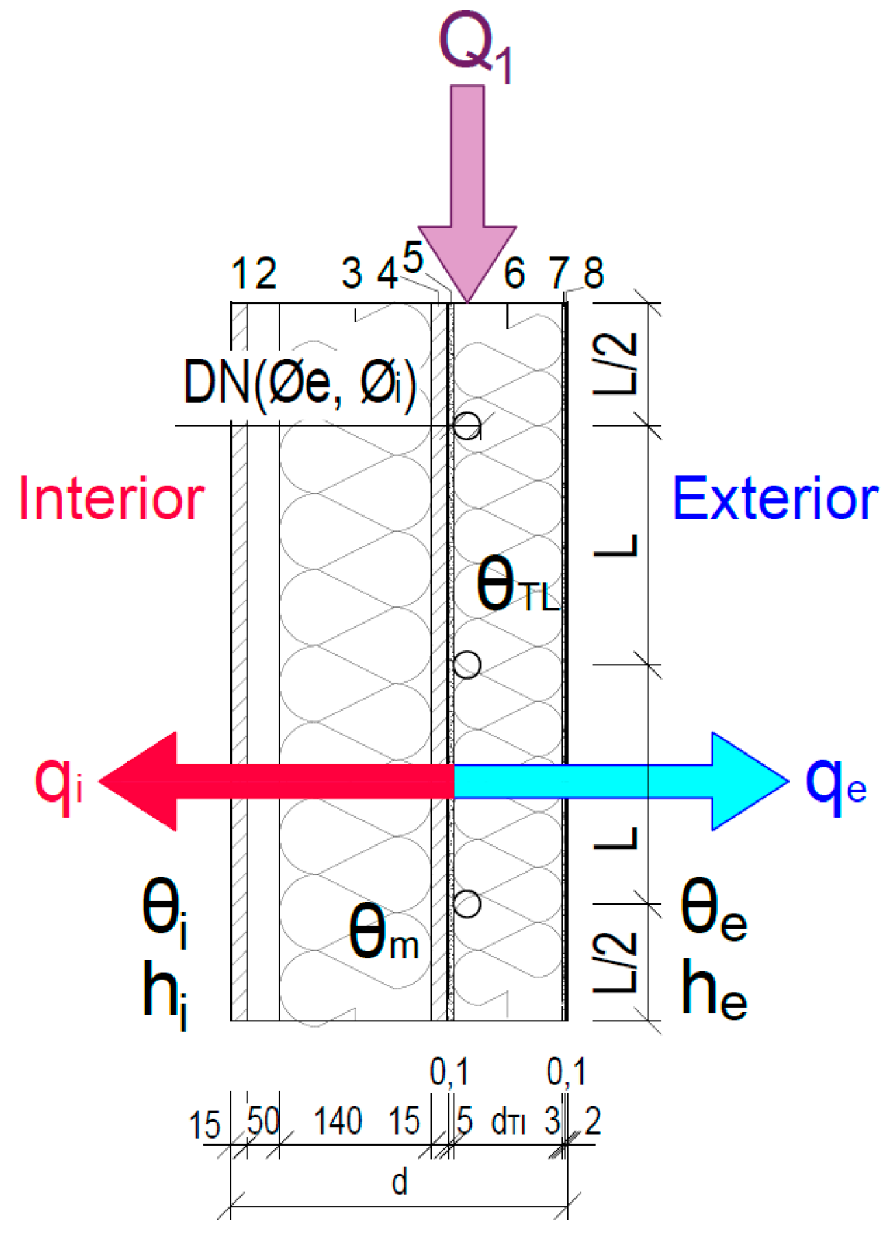
Based on these theoretical backgrounds, a simplified mathematical–physical model of the lightweight building envelope of modular and panelised buildings was developed. In this model, a two-dimensional non-stationary heat conduction equation was considered to verify the ATP as a function of the thermal barrier through a parametric study and computer simulation in ANSYS (ANSYS Fluent R2 (2024)) on a defined domain. The fragment of the perimeter wall was designed as follows: the interior consisted of a plasterboard attached to a wooden lathing, which was connected to the load-bearing part of the structure, consisting of load-bearing columns of the wooden perimeter structure with dimensions of 60 mm × 140 mm, filled with thermal insulation with a thickness of 140 mm, see Figure 3. On the outside, the fragment was insulated with EPS thermal insulation into which the active thermal protection pipes were inserted. The exterior side of the fragment was made of plaster. The thermal and technical properties of the materials used are presented in Table 1.
In a parametric study, ATP fragments were analyzed in the energy function of the thermal barrier with the following variables: internal temperature, external temperature, thickness of the external thermal insulation, and average temperature in the ATP layer. Additional variables were added for computer simulation purposes (Table 2): outer pipe diameter, inner pipe diameter, and axial distance of the pipes.
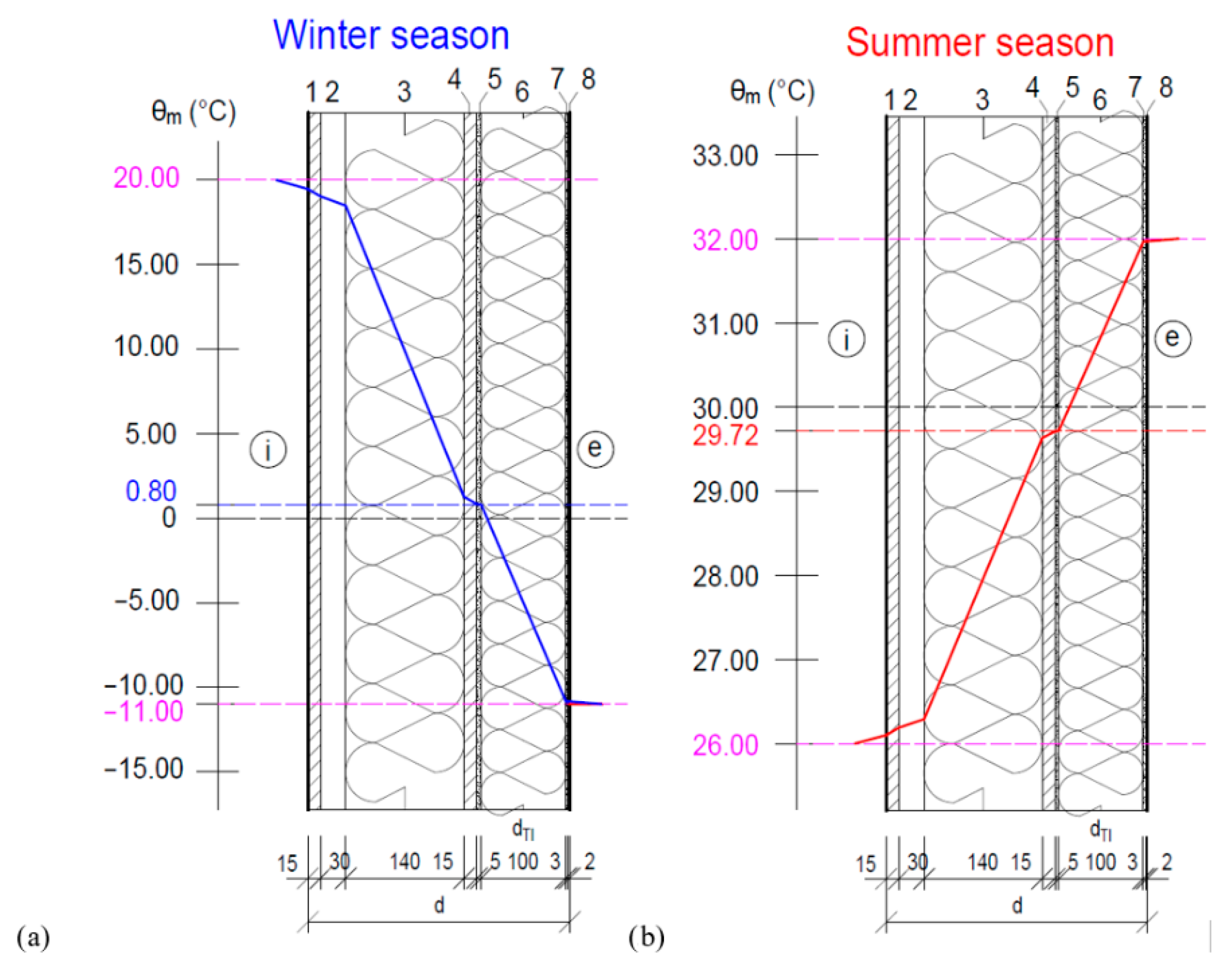
Figure 4 illustrates the temperature history within the structure, which is unaffected by the application of integrated energy elements. The blue curve shows the temperatures during the winter period, while the red curve shows the temperatures during the summer period.
The following boundary conditions are set for the winter period:
  • indoor temperature θi = 20 °C;
  • outdoor temperature θe = −11 °C.
For the summer period, the boundary conditions are:
  • indoor temperature θi = 26 °C;
  • outdoor temperature θe = 32 °C.
For both seasons, the boundary conditions are the same:
  • heat transfer coefficient at the internal surface horizontally hi = 8 W/(m2K);
  • heat transfer coefficient on the external surface in winter he = 23 W/(m2K).

2.2.3. Parametric Study of the Energy Potential of a Lightweight Envelope with TB

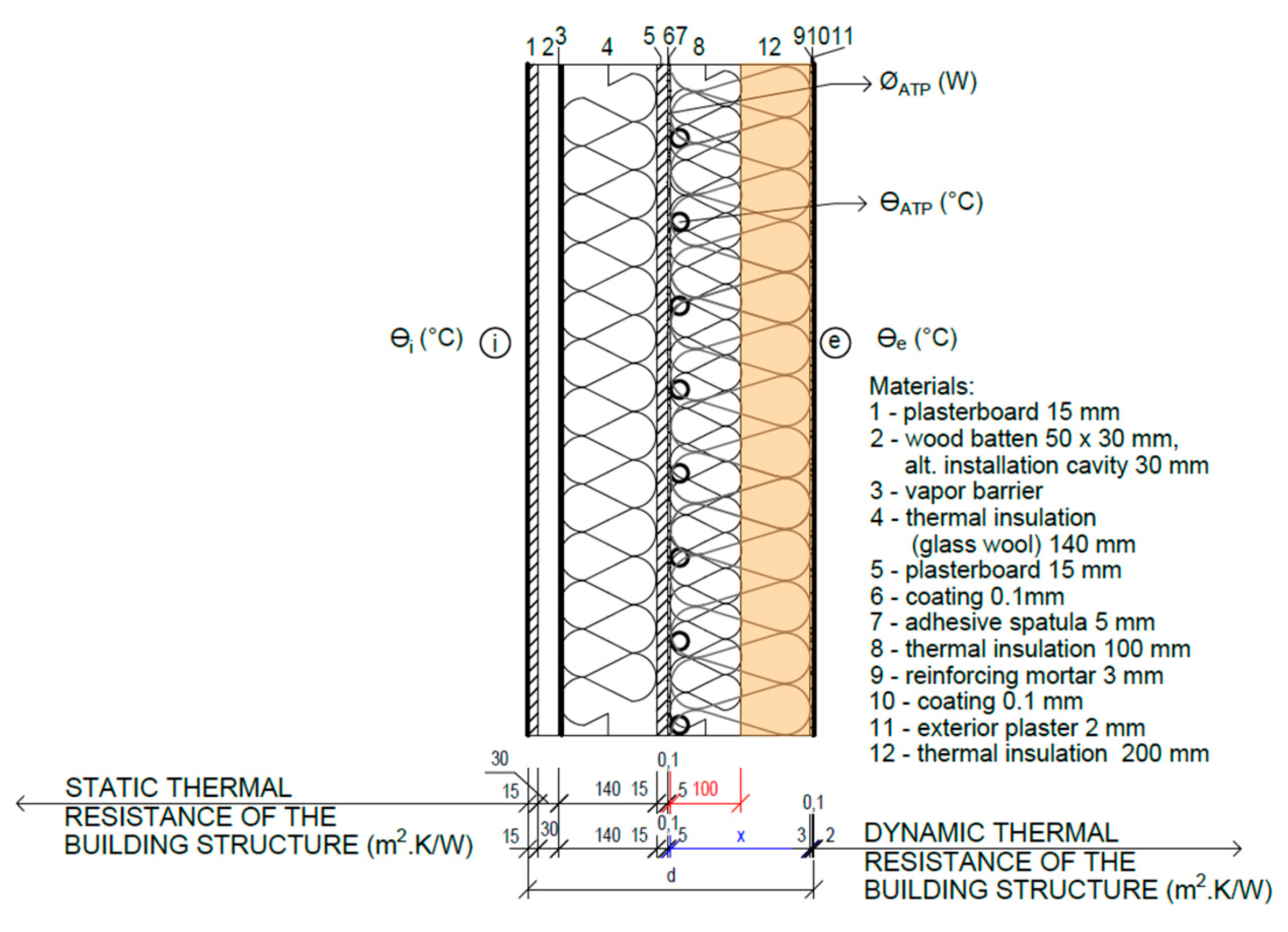
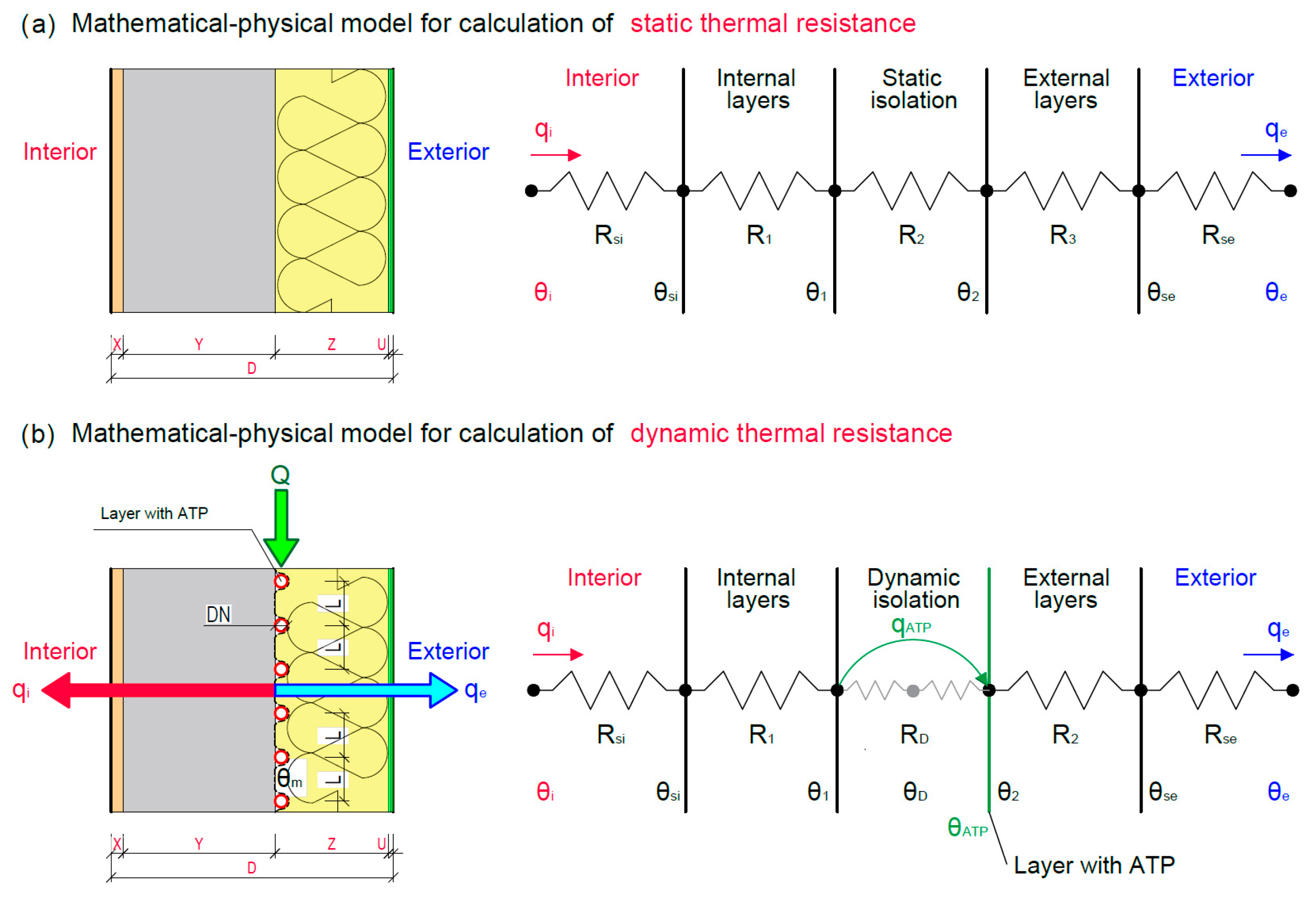
The objective of the parametric study is to determine the energy savings potential of ATP in the TB energy function for lightweight modular and panelized buildings. The parametric study shall be conducted for a heating period with a TB temperature change of up to θm, ATP = 20 °C, corresponding to the indoor temperature of the heated space, and for a cooling period with a TB temperature change of up to θm, ATP = 26 °C, or 20 °C in the case of a requirement to achieve an extreme indoor temperature in the cooled space. The physical principle of TB is based on dynamic thermal resistance—a controlled temperature change between the static load-bearing structure and the external thermal insulation layer. The principle of the TB energy function and the distinction between static and dynamic thermal resistance are illustrated in Figure 5 and Figure 6. By changing the temperature in the TB layer, the dynamic thermal resistance of the building structure RDYN ((m2.K)/W), respectively, the dynamic heat transfer coefficient UDYN (W/(m2.K)) changes, which ultimately affects the dynamic thickness of the thermal insulation dDYN (m).
For the purpose of the parametric study, the following boundary conditions were defined as follows:
Heating period:
  • θi—indoor temperature (θi = 20 °C);
  • θe—outdoor temperature (θe = −11 °C).
Cooling period:
  • θi—indoor temperature (θi = 26 °C, extreme requirement θi = 20 °C);
  • θe—outdoor temperature (θe = 32 °C, extreme temperature due to climate change θe = 36 °C).
The building structure without TB, represented by the thickness of the exterior thermal insulation d = 100 mm, has a constant static thermal resistance RSTATIC ((m2.K)/W) characterized by the thickness and thermal properties of the individual building materials of which it is composed. The dynamic thermal resistance RDYN ((m2.K)/W) and the dynamic thermal insulation thickness dDYN (m) is represented by the variable x (mm), which is a function of the heat input of the ΦATP (W) and the temperature in the θATP (°C).

2.2.4. Computer Simulation of a Lightweight Building Envelope with ATP

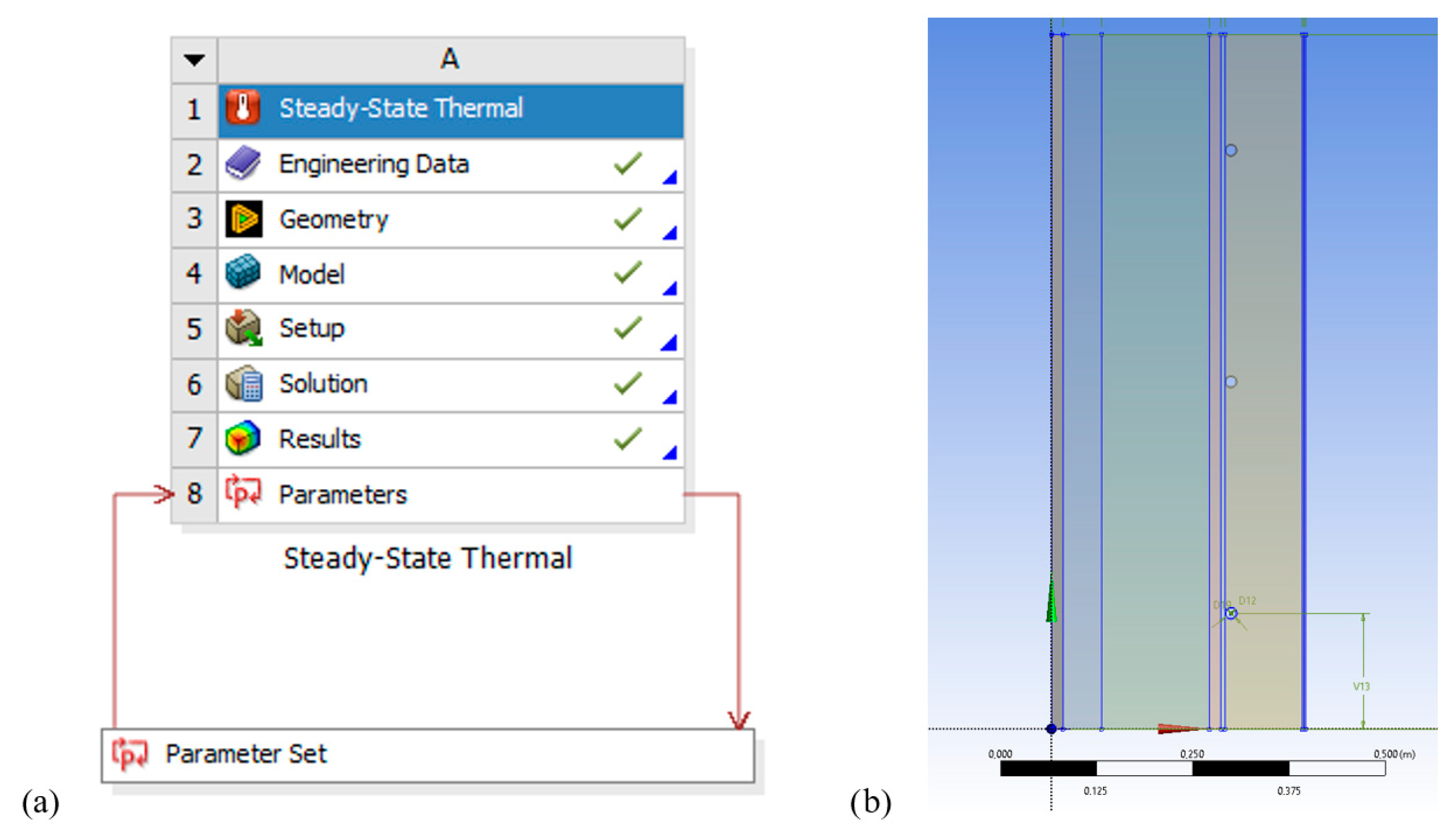
The simulation of the wall construction with integrated energy-active elements (ATP) was performed in ANSYS Mechanical, Figure 7 [89,104]. In this case, these energy-active elements act as a thermal barrier. This thermal barrier does not affect heating or cooling but serves to prevent heat loss to the exterior and heat gain to the interior.
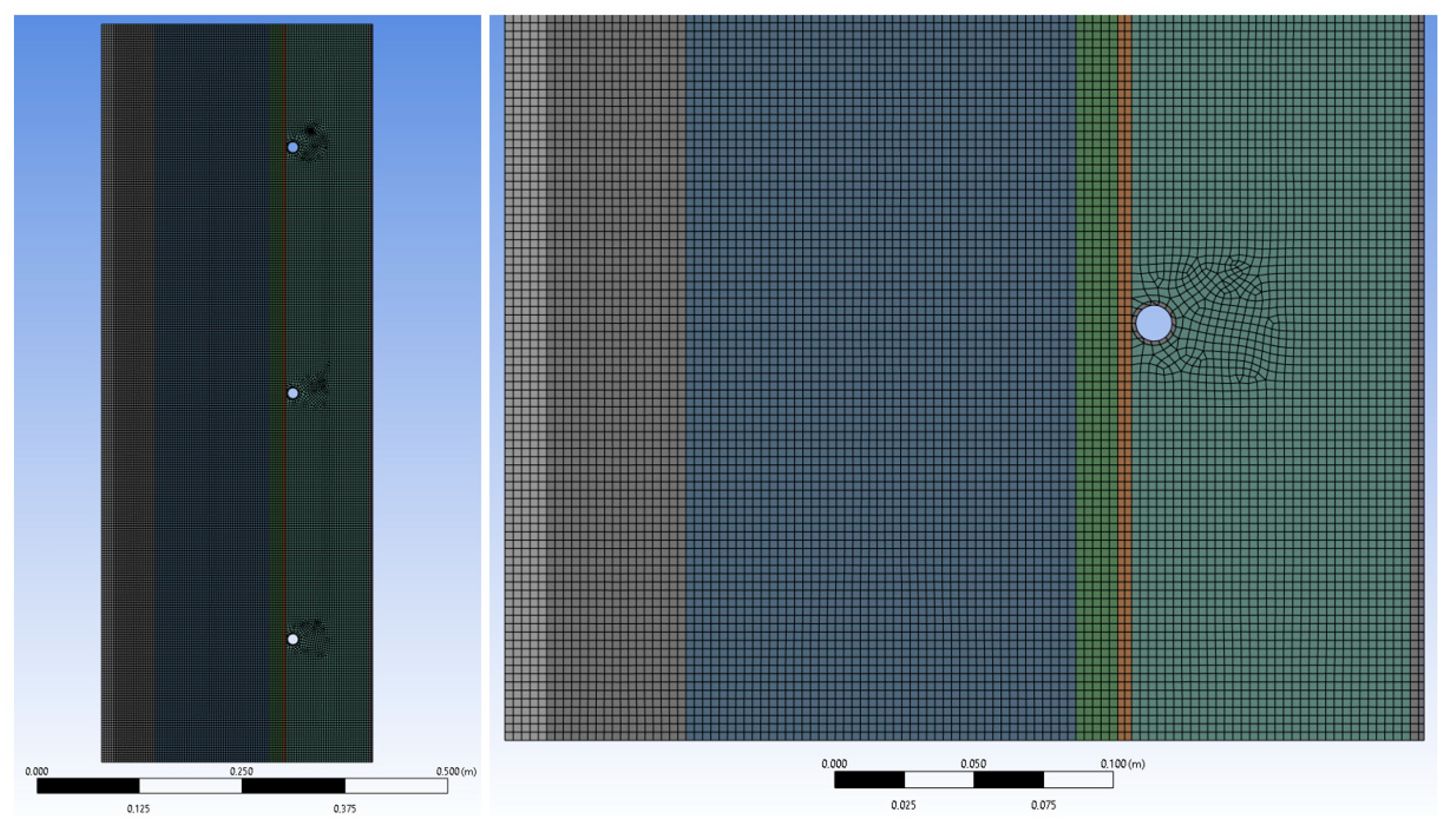
The 2D model under consideration encompasses three axial distances of heating pipes, designated L = 100 mm, 150 mm, and 200 mm, and three thicknesses of thermal insulation, denoted as d = 100 mm, 150 mm, and 200 mm, respectively. By computer simulation, the optimum thickness of thermal insulation and the optimum axial distance of the pipes is determined. The parametric study’s assumption and hypothesis is verified as follows: at the mean temperature of the heat transfer medium θm,ATP = +6 °C supplied to the ATP layer, the thermal insulation thickness can be eliminated from d = 200 mm to 100 mm. The mesh creation for the model was adapted to the requirements of the simulation, with the element size set to 3−003 m, as shown in Figure 8 [104].
Three boundary conditions were defined for this simulation:
  • Convection on the interior layer:
    • θi—interior temperature (20 °C);
    • hi—heat transfer coefficient on the inner surface horizontally (hi = 8 W/(m2·K)).
2.
Convection on the exterior layer:
  • θe—exterior temperature (−11 °C);
  • he—heat transfer coefficient on the outer surface in winter (he = 23 W/(m2·K)).
3.
Water temperature in the pipes:
  • θTL—heat transfer fluid temperature (6 °C).
On the left (interior surface) and right wall (exterior surface), Newton’s boundary conditions are applied in the form of [104]:
qj = hj (θ(x,y,t) − θj)
qj = −λ∇θ.n
Here qj—radiant heat flux density in the direction of the outer normal (W/m2); qi—radiant heat flux density directed towards the interior (W/m2); qe—radiant heat flux density directed towards the exterior (W/m2); hj—heat transfer coefficient between the computational domain and the external environment; hi—heat transfer coefficient on the inner surface horizontally (hi = 8 W/(m2·K)); he—heat transfer coefficient on the outer surface during the winter period (he = 23 W/(m2·K)); θ(x;y;t)—temperature as a function of three spatial variables and time (°C); θj—temperature in the environment (°C); θi—interior temperature (θi = 20 °C); θe—exterior temperature (θe = −11 °C); θm—temperature in the construction (°C); —gradient; n—unit vector of the outer normal.
We solved the heat transfer problem of active thermal protection, where a two-dimensional transient heat conduction equation was applied to the defined area (specified wall structure). The mathematical relationship that applies is [89,104] the following equation:
c ( x , y ) ρ ( x , y ) θ ( x , y , t ) t =   x λ ( x , y ) θ x , y , t x +   y λ ( x , y ) θ x , y , t y ,
and after simplification:
c ρ   θ t = 𝛻 · ( λ 𝛻 θ )
Here c(x,y) is specific heat capacity of the material (J/(kg·K)), ρ(x,y) is material density (kg/m3), θ(x,y,t) is temperature as a function of three spatial variables and time (°C), t is time (s), x, y is spatial coordinates, λ(x,y) is thermal conductivity coefficient, which varies for each of the isotropic materials in the computational domain (W/(m·K)), is gradient, ∇· is divergence, is partial derivative [104].

3. Results

3.1. Results of the Parametric Study

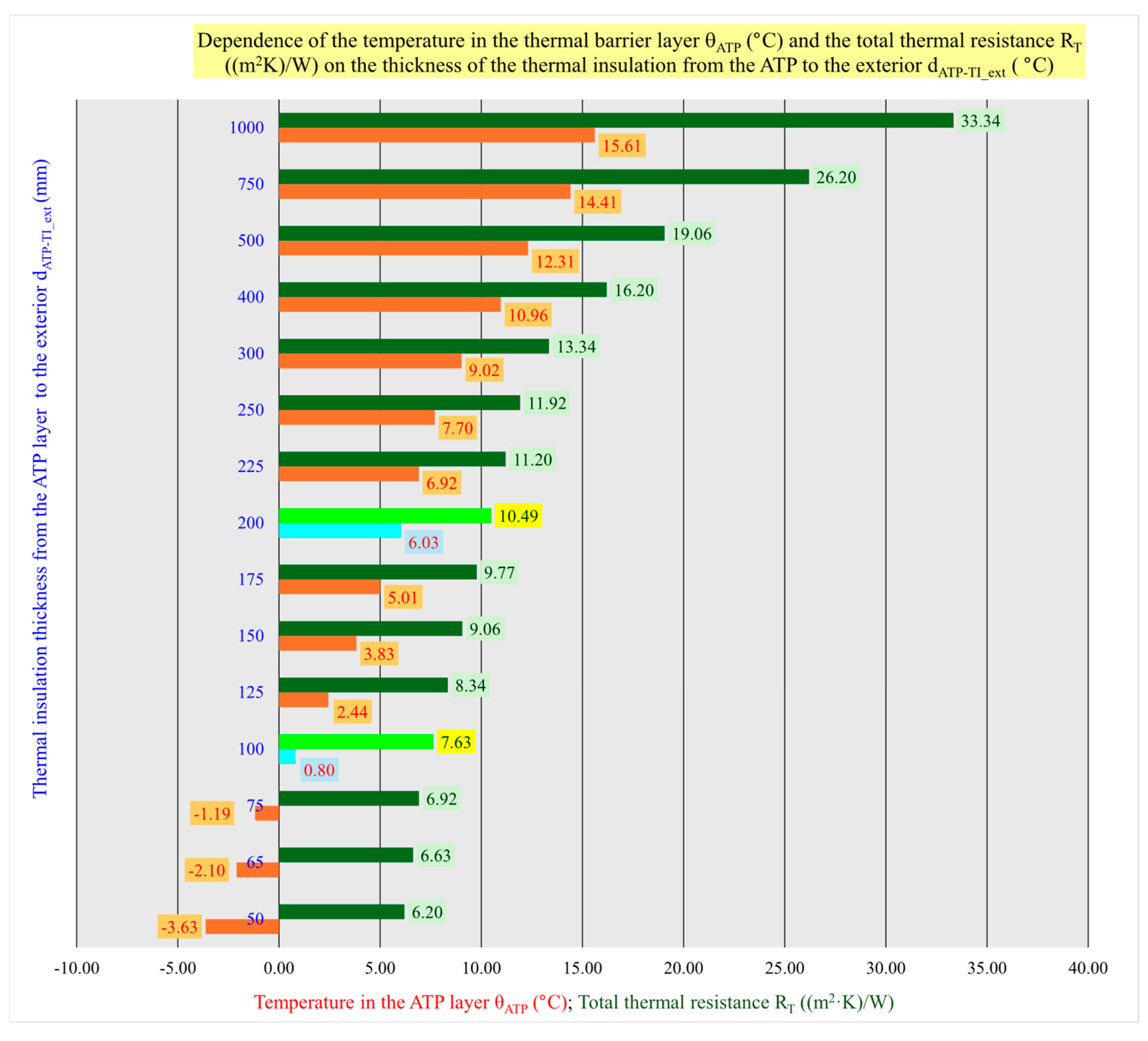
From the results of the parametric analyses published in previous papers [10,14,15,16,18], it is clear that the temperature between the static load-bearing structure and the thermal insulation layer in the lightweight envelope of modular and panelized buildings for the mathematical–physical model investigated is θm,ATP = 0.80 °C for an EPS thickness of d = 100 mm and θm = 6.03 °C for an EPS thickness of d = 200 mm. These results show that the heat delivered by the heat transfer medium to the layer causes an increase in the temperature of the layer of Δθ = 5.23 °C, on the basis of which we can eliminate the required thickness of the thermal insulation by Δd = 100 mm. For a thermal insulation thickness of d = 100 mm, the heat transfer coefficient is U100 = 0.131 W/(m2K), at a temperature of θm,ATP = +6 °C in the ATP layer, which is sufficient for the energy function of the thermal barrier, the dynamic heat transfer coefficient is UDYN_200 = 0.095 W/(m2K).
Based on the results of the parametric study, namely that the temperature of θm,ATP = +6 °C in the thermal insulation layer, which can be provided, for example, by cold water from a public tap or a well without the need for thermal energy supply, meets the target values and requirements of thermal engineering standards for building structures by its dynamic thermal resistance, we focus the computer simulations on the optimization of the axial spacing of the pipes in the ATP and the thickness of the thermal insulation at this temperature.
However, the thermal barrier used in the lightweight envelope of modular and panelized buildings has an even greater potential to increase the thermal resistance of the building structure and, thus, save energy in the heating season, up to a temperature in the ATP layer of θm,ATP = +20 °C, which is equal to the internal temperature. A heat carrier with an average temperature of θm,H = +20 °C can be obtained in the building, for example, from the return water of a low-temperature heating system, RES, or waste heat. A temperature in the ATP layer close to the indoor temperature, e.g., θm,ATP = +19.8 °C, represents a dynamic thermal resistance of RDYN = 719 ((m2.K)/W), which is a dynamic heat transfer coefficient of UDYN = 0.00139 (W/(m2.K)). These values represent a dynamic thermal insulation thickness of dDYN = 25 m.
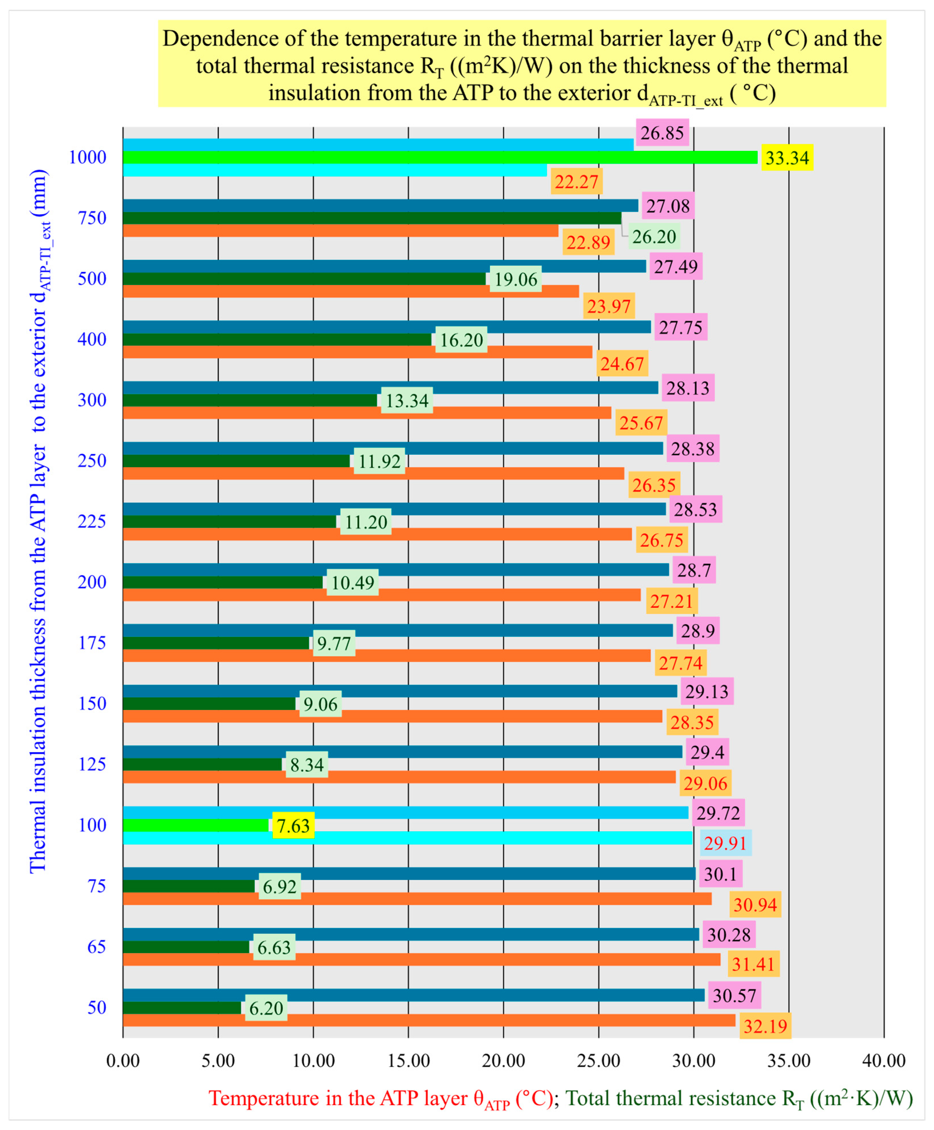
Table 3 presents the results of the parametric study conducted on a mathematical–physical model of the lightweight envelope of modular and panelized buildings with integrated ATP. Based on the variation in the thermal insulation thickness from d = 50 mm to d = 1000 mm, the values of the temperatures in the ATP layer, the total thermal resistance, and the total heat transfer coefficient of the building envelope were calculated. A graphical evaluation and analysis of the calculated values of the ATP layer temperatures and total thermal resistances is presented in Figure 9. For a dynamic thermal insulation thickness dDYN = 1000 mm, the mean temperature in the ATP layer is θm,ATP = +15.61 °C, the dynamic heat transfer coefficient is UDYN = 0.030 (W/(m2.a)), and the dynamic thermal resistance is RDYN = 33.344 ((m2.K)/W), which is approximately 4.4 times greater than the static thermal resistance of the building structure without the use of ATP RSTAT = 7.63 ((m2.K)/W).
A parametric study for the cooling period was also developed. The detailed results are presented in Table 4. The graphical representation and analysis of the calculated values of ATP layer temperatures and total thermal resistances are presented in Figure 10. During the cooling period (an internal temperature of θi = +26 °C and an external temperature of θe = +32 °C), the potential for energy savings in comparison with the heating period is also very high, given that the temperature in the ATP layer of θm,ATP = +26.10 °C represents a total thermal resistance of the building structure of up to RDYN = 290.487 ((m2.K)/W). The dynamic thermal resistance is approximately 38 times greater than the thermal resistance of the building structure in the absence of a thermal barrier. In this case, the dynamic heat transfer coefficient would be UDYN = 0.003 (W/(m2.K)). These values represent a dynamic thermal insulation thickness of dDYN = 10 m.
Figure 10 illustrates the dependence of the mean temperature in the ATP layer on the change in thermal insulation thickness from d = 50 mm to d = 1000 mm, as well as for extreme values: an internal temperature of θi = +20 °C and an external temperature of θe = +36 °C. If we consider a mean temperature in the ATP close to the internal temperature of θi = +20 °C, for example, θm,ATP = +20.11 °C, then the dynamic thickness of the thermal insulation would be dDYN = 25 m, the dynamic heat transfer coefficient UDYN = 0.001 (W/(m2.a)), and the dynamic thermal resistance RDYN = 719.058 ((m2.K)/W), which is approximately 94 times greater than the static thermal resistance of the building structure without the use of ATP RSTAT = 7.63 ((m2.K)/W).
A parametric study for the cooling period was also developed. The detailed results are presented in Table 4.
Graphical representation and analysis of the calculated values of ATP layer temperatures and total thermal resistances are presented in Figure 10. During the cooling period (internal temperature of θi = +26 °C and external temperature of θe = +32 °C), the potential for energy savings in comparison with the heating period is also very high, given that the temperature in the ATP layer of θm,ATP = +26.10 °C represents a total thermal resistance of the building structure of up to RDYN = 290.487 ((m2.K)/W). The dynamic thermal resistance is approximately 38 times greater than the thermal resistance of the building structure in the absence of a thermal barrier. In this case, the dynamic heat transfer coefficient would be UDYN = 0.003 (W/(m2.K)) and these values represent a dynamic thermal insulation thickness of dDYN = 10 m.
Figure 10 illustrates the dependence of the mean temperature in the ATP layer on the change in thermal insulation thickness from d = 50 mm to d = 1000 mm, as well as for extreme values: internal temperature of θi = +20 °C and external temperature of θe = +36 °C. If we consider a mean temperature in the ATP close to the internal temperature of θi = +20 °C, for example, θm,ATP = +20.11 °C, then the dynamic thickness of the thermal insulation would be dDYN = 25 m, the dynamic heat transfer coefficient UDYN = 0.001 (W/(m2.a)) and the dynamic thermal resistance RDYN = 719.058 ((m2.K)/W), which is approximately 94 times greater than the static thermal resistance of the building structure without the use of ATP RSTAT = 7.63 ((m2.K)/W).

3.2. Results of the Computer Simulation

Computer simulations were carried out for different thicknesses of thermal insulation with ATP d = 100 mm, 150 mm, and 200 mm and three different axial distances between these pipes L = 100 mm, 150 mm, and 200 mm. The dimensions of the tubes remained unchanged at Ø16 × 1.5 mm (13 mm inner diameter). The theoretical assumption is that the average temperature in the ATP layer would be θm,ATP = +6 °C.
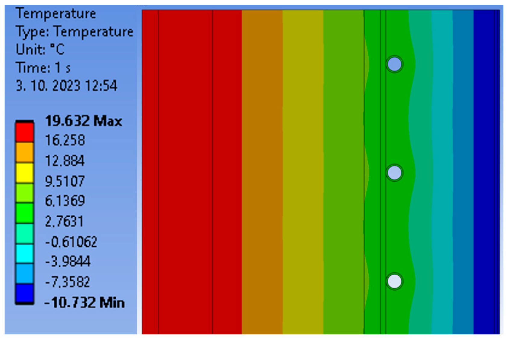
Figure 11 shows the temperature history for a thermal insulation with a thickness of d = 100 mm, a distance between the pipe centrelines of L = 100 mm, and pipe dimensions of Ø16 × 1.5 mm.
Table 5 summarizes the results of the computer simulation for the ATP with a Ø16 × 1.5 mm tube for tube spacings of L = 100 mm, 150 mm, and 200 mm, also for thermal insulation thicknesses of d = 100 mm, 150 mm, and 200 mm, where we report the average total radiant flux density, the radiant flux density at the outer surface of the pipe, the radiant flux density at the inner surface of the pipe, the average total temperature in the structure, the minimum temperature at the pipe joint, and the maximum temperature at the pipe joint.
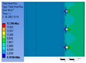
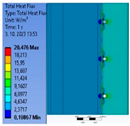
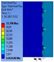
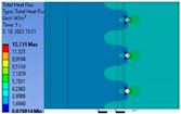
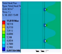
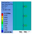
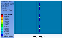
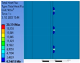
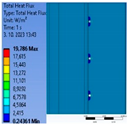
Table 6 shows the graphical outputs = results of the total radiant flux for different variations in thermal insulation thickness d = 100 mm, 150 mm, and 200 mm and pipe centre distances L = 100 mm, 150 mm, and 200 mm.
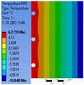
Table 7 shows the graphical outputs = simulation results of the temperature distribution in the structure. From the graphical representation, it can be concluded that at the analyzed thermal barrier temperature θm, ATP = +6 °C, the optimum thermal insulation thickness is d = 100 mm. Increasing the thickness beyond this value (e.g., d = 150 mm or d = 200 mm) has been shown to reduce the energy efficiency of the system. The heat distribution between the layers of the lightweight building envelope becomes ineffective in this case.
The axial distance between the pipes is found to be a pivotal factor in ensuring optimal performance. The graphical representation of the computer simulation results indicates that the optimum axial distance between the pipes is L = 150 mm. In contrast, smaller axial distances of L = 100 mm result in excessive heat accumulation and unnecessary heat dissipation, while larger axial distances of L = 200 mm compromise the continuity and uniformity of the thermal coupling between the pipes.

4. Discussion

It is evident from the findings of the parametric study and computer simulation that the active thermal protection (ATP) system is efficacious in diminishing the heat flux through the building structure in the energy function of the thermal barrier for the examined lightweight envelope of modular and panelized buildings. This finding is further validated by simulations conducted in ANSYS Mechanical, which corroborate the theoretical assumptions derived from the parametric study. The optimal thermal insulation thickness, determined to be d = 100 mm, is substantiated when the thermal resistance of the lightweight building envelope under consideration is R100 = 7.63 ((m2.K)/W). It is important to note that when the mean temperature of the ATP heat transfer medium is set to θm,ATP = +6 °C, the dynamic thermal resistance is assumed to be RDYN_200 = 10.49 (m2.K)/W. This represents a 27.24% increase in thermal resistance compared to a building structure in which ATP is not used and the dynamic thermal insulation thickness is twice as thick, i.e., dDYN = 200 mm. This result aligns with the findings of other studies, which indicate that the optimal thickness of thermal insulation incorporating energy-active components constitutes a technically, economically, and environmentally sustainable solution.
The thermal insulation thickness d = 100 mm represents the optimum solution for the investigated lightweight building envelope construction for modular and panelized buildings, also from the point of view that when the energy function TB is shut down (pumps shut down for any reason), at an internal temperature of θi = +20 °C and an external temperature of θe = −11 °C, the mean temperature of the heat transfer medium in the ATP would be θm,ATP = +0.8 °C, so this internal ATP circuit does not need to be filled with a frost-resistant heat transfer medium.
An accurate definition of thermal–moisture properties for all construction layers, model parameters, and boundary conditions, such as convection and heat carrier temperature, is essential for reliable simulation results. Parametric analysis, verified by computer simulation, predicts that at a mean thermal barrier temperature of approximately θm, ATP = +6 °C, and typical winter conditions (θi = 20 °C indoor temperature and θe = −11 °C outdoor temperature), the ATP system can perform its task effectively. By analogy, it can be argued that ATP in the thermal barrier (TB) energy function is capable of performing its function even during the cooling period, with a high potential for energy savings, under typical summer conditions (θi = 26/20 °C indoor temperature and θe = 32/36 °C outdoor temperature).
At the analyzed thermal barrier temperature of θm, ATP = +6 °C, the optimum thermal insulation thickness is d = 100 mm, as increasing the thickness beyond this value (e.g., d = 150 mm or d = 200 mm), reduces the energy efficiency of the system. The heat distribution between the layers of the lightweight building envelope becomes inefficient in this case. The axial distance between the pipes is crucial for optimum performance. Based on parametric analysis and computer simulation, we conclude that the optimum axial spacing of the pipes is L = 150 mm. Smaller pipe centerline distances L = 100 mm lead to excessive heat build-up and unnecessary heat loss, while larger pipe centerline distances L = 200 mm reduce the continuity and uniformity of the thermal coupling between the pipes.
The ATP application enables one to reduce the thermal insulation thickness requirements and improve the energy efficiency of combined building–energy systems, particularly for applications in lightweight envelopes of modular and panelized buildings. This lowers investment costs for materials, increases energy sustainability and resilience, and makes buildings more adaptable to climate change. The combination of ATP with renewable energy sources, waste heat, and low-temperature heating or high-temperature cooling optimizes the operation of energy systems in buildings, increases energy savings, and contributes to the reduction in greenhouse gases, especially CO2, thus actively contributing to the decarbonisation of the building sector.

5. Conclusions

This work demonstrates the analysis, evaluation, and optimization of the energy performance of active thermal protection (ATP) integrated into the lightweight envelope of modular and panelised buildings. A comprehensive review of the extant literature on the subject was conducted, encompassing research contributions from multiple authors. The results achieved in this field on a global scale are presented. This study also led to the development of a mathematical and physical model of the lightweight envelope wall. A parametric study was undertaken to examine the energy efficiency of TB during both heating and cooling periods. The axial distance of the tubes and the thickness of the thermal insulation were optimized using a computer simulation.
Based on the simulation of the wall envelope fragment, we arrived at the following findings, which are key to the mathematical–physical (parametric) model:
  • it is necessary to properly define the thermal–moisture properties of all layers that make up the construction;
  • it is essential to identify the parameters of the model that will be subject to changes;
  • the boundary conditions such as convection on the inner and outer surfaces of the wall and the temperature of the heat transfer fluid in the pipes, must be defined;
  • proper mesh generation is essential.
From the results of previous studies and the parametric study of ATP in the TB energy function presented in this work for the heating season, it can be concluded that at an average thermal barrier temperature of approximately θm,ATP = +6 °C, the dynamic thermal resistance is approximately 27.24% higher compared to the thermal resistance of a building structure without integrated ATP.
By analogy, it can be argued that ATP in the energy function of the thermal barrier (TB), during the cooling period (boundary conditions indoor temperature of θi = +26/20 °C and outdoor temperature θe = +32/36 °C), has the potential for energy savings in comparison to the heating period, which is also very high, given that the temperature in the ATP layer of θm,ATP = +26.10 °C represents a total thermal resistance of the building structure of up to RDYN = 290.487 ((m2.K)/W), and the dynamic thermal resistance is approximately 38 times greater than the thermal resistance of the building structure in the absence of a thermal barrier. In this case, the dynamic heat transfer coefficient would be UDYN = 0.003 (W/(m2.K)). These values represent a dynamic thermal insulation thickness of dDYN = 10 m.
Computer simulations have shown the following:
  • thermal insulation thickness of d = 100 mm towards the exterior in front of the ATP layer in the energy function TB is optimal in terms of radiant flux, temperature differences in the structure, and thermal resistance as long as the average temperature of the heat transfer medium is approximately θm,ATP = +6 °C;
  • thermal insulation thickness d = 100 mm represents the optimum solution for the investigated lightweight building envelope construction for modular and panelized buildings, also from the point of view that when the energy function TB is shut down the mean temperature of the heat transfer medium in the ATP would be θm,ATP = +0.8 °C, so this internal ATP circuit does not need to be filled with a frost-resistant heat transfer medium;
  • for a thermal insulation thickness of d = 100 mm, an axial distance between the pipes of L = 150 mm is the most appropriate, because at an axial distance of L = 100 mm there is excessive heat production, which increases heat loss. At an axial distance of L = 200 mm the continuity and uniformity of the thermal barrier between the pipes is almost broken.
Based on the demonstration of results from the parametric study and computer simulations, we can assume that ATP has high potential in designing energy-sustainable, resilient, and climate-adaptive buildings. The utilization of cold water, whether from a well or a public water supply, without undergoing any thermal treatment, serves to enhance the thermal resistance of a building structure in a straightforward yet effective manner. This approach aligns with the philosophical tenet expressed by Leonardo da Vinci—“Simplicity is the ultimate sophistication.”

Author Contributions

V.M.: Conceptualization, resources, parametric studies and computer simulations, data curation, writing—original draft, and writing—review and editing. D.K.: conceptualization, methodology, validation, formal analysis, resources, parametric studies, data curation, writing—original draft, and writing—review and editing. S.M.: conceptualization, methodology, validation, investigation, resources, and parametric studies and computer simulations. Z.S.: conceptualization, methodology, validation, resources, writing—original draft, and writing—review and editing. M.M.: conceptualization, resources, and data curation. A.P.: conceptualization, resources, and data curation. M.F.: conceptualization, resources, and data curation. M.B.: conceptualization, resources, and data curation. All authors have read and agreed to the published version of the manuscript.

Funding

The research work in the field of combined building–energy systems is significantly financially supported by EHBconsulting Ltd. (Nitra, Slovakia), for which we express our sincere thanks.

Institutional Review Board Statement

Not applicable.

Informed Consent Statement

Not applicable.

Data Availability Statement

Data sharing policy does not apply to this article.

Acknowledgments

This work was supported by the Ministry of Education, Science, Research and Sport of the Slovak Republic under the VEGA grant 01/0118/23 and the VEGA grant 01/0482/25.

Conflicts of Interest

The authors declare that they have no known competing financial interests or personal relationships that could have influence the work reported in this paper.

Abbreviations

The following abbreviations are used in this manuscript:
ANSYSName of engineering simulation software
AOTRAverage operative temperature reduction
ATFRAverage temperature fluctuation reduction
ATPActive thermal protection
BEPSBuilding energy performance simulation
CFDComputational fluid dynamics
CNKIChina national knowledge infrastructure
CO2Carbon dioxide
DHWDomestic hot water
EPSExpanded polystyrene
EUEuropean Union
FEMathematical–physical model (computer code) of a software package ABAQUS for finite element analysis and computer-aided engineering
HVACHeating, ventilation, and air conditioning
IEAInternational energy agency
IFCIndustry foundation classes
MPCModel predictive control
MITRMaximum indoor temperature reduction
nZEBNear-zero energy buildings
PCMPhase change materials
RESRenewable energy sources
SDGsSustainable Development Goals
STNSlovak technical norm
TABEsThermally activated building envelopes
TBThermal barrier
TLTime lag
TOPTemperature operative
UNUnited Nations
WIHPWall-implanted heat pipe

References

  1. Directive (EU) 2024/1275 of the European Parliament and the Council (of 24 April 2024) on the Energy Performance of Buildings. Available online: https://eur-lex.europa.eu/eli/dir/2024/1275/oj/eng (accessed on 23 March 2025).
  2. United Nations Office at Vienna (UNOV). Available online: https://unis.unvienna.org/unis/en/topics/sustainable_development_goals.html (accessed on 23 March 2025).
  3. Kalús, D. UTILITY MODEL SK 5749 Y1 (UTILITY MODEL): Method of Operation of a Combined Construction-Energy System of Buildings and Equipment. Date of Entry into Force of the Utility Model: 1.4.2011. In Vestník ÚPV SR č.: 5/2011, 23p. Spôsob Prevádzky Kombinovaného Stavebno-Energetického Systému Budov a Zariadenie: Číslo Prihlášky 5027-2010, Zverejnená 8. 11. 2010 vo Vestníku ÚPV SR č. 11/2010; Úrad Priemyselného Vlastníctva Slovenskej Republiky: Banská Bystrica, Slovakia, 2011; 23p. Available online: https://wbr.indprop.gov.sk/WebRegistre/UzitkovyVzor/Detail/5027-2010 (accessed on 23 March 2025).
  4. Kalús, D. UTILITY MODEL SK 5729 Y1 (UTILITY MODEL): Samonosný Tepelnoizolačný Panel pre Systémy s Aktívnym Riadením Prechodu Tepla. [Self-Supporting Thermal Insulation Panel for Systems with Active Heat Transfer Control]. Date of Entry into Force of the Utility Model: 28.2.2011. In Vestník ÚPV SR No. 4/2011, Banská Bystrica, Slovak Republic, 32 p. Samonosný Tepelnoizolačný Panel pre Systémy s Aktívnym Riadením Prechodu Tepla: Číslo Prihlášky UV 5030-2010, Zverejnená 7. 10. 2010 vo Vestníku ÚPV SR č. 10/2010; Úrad Priemyselného Vlastníctva Slovenskej Republiky: Banská Bystrica, Slovakia, 2011; 32p. Available online: https://wbr.indprop.gov.sk/WebRegistre/UzitkovyVzor/Detail/5030-2010 (accessed on 23 March 2025).
  5. Kalús, D. UTILITY MODEL SK 5725 Y1 (UTILITY MODEL): Tepelnoizolačný Panel pre Systémy s Aktívnym Riadením Prechodu Tepla: Číslo Prihlášky UV 5031-2010, Zverejnená 7.10. 2010 vo Vestníku ÚPV SR č. 10/2010; Úrad Priemyselného Vlastníctva Slovenskej Republiky: Banská Bystrica, Slovakia, 2011; 63p. Available online: https://wbr.indprop.gov.sk/WebRegistre/UzitkovyVzor/Detail/5031-2010 (accessed on 23 March 2025).
  6. Kalús, D. EUROPEAN PATENT EP 2 572 057 B1. Heat-Insulating Panel with Active Regulation of Heat Transfer. International Application Number: PCT/SK2011/000004, International Publication Number: WO 2011/146025 (24.11.2011 Gazette 2011/47). 15 October 2014. 67p. Available online: https://register.epo.org/application?number=EP11716446&tab=main&lng=en10 (accessed on 23 March 2025).
  7. Kalús, D.; Gašparík, J.; Janík, P.; Kubica, M.; Šťastný, P. Innovative building technology implemented into facades with active thermal protection. Sustainability 2021, 13, 4438. [Google Scholar] [CrossRef]
  8. Kalús, D.; Mučková, V.; Koudelková, D. Energy, Economic and Environmental Assessment of Thermal Barrier Application in Building Envelope Structures. Coatings 2021, 11, 1538. [Google Scholar] [CrossRef]
  9. Kalús, D.; Koudelková, D.; Mučková, V.; Sokol, M.; Kurčová, M.; Šťastný, P. Parametric study of the energy potential of a building’s envelope with integrated energy-active elements. Acta Polytech. 2022, 62, 595–606. [Google Scholar] [CrossRef]
  10. Kalús, D.; Koudelková, D.; Mučková, V.; Sokol, M.; Kurčová, M. Contribution to the Research and Development of Innovative Building Components with Embedded Energy-Active Elements. Coatings 2022, 12, 1021. [Google Scholar] [CrossRef]
  11. Mučková, V.; Kalús, D.; Koudelková, D.; Kurčová, M.; Straková, Z.; Sokol, M.; Ingeli, R.; Šťastný, P.; Janík, P. Contribution to Active Thermal Protection Research—Part 1 Analysis of Energy Functions by Parametric Study. Energies 2023, 16, 4391. [Google Scholar] [CrossRef]
  12. Kalús, D.; Mučková, V.; Koudelková, D.; Kurčová, M.; Straková, Z.; Sokol, M.; Ingeli, R.; Šťastný, P.; Janík, P. Contribution to Active Thermal Protection Research—Part 2 Verification by Experimental Measurement. Energies 2023, 16, 4595. [Google Scholar] [CrossRef]
  13. Mučková, V.; Kalús, D.; Koudelková, D.; Kurčová, M.; Straková, Z.; Sokol, M.; Ingeli, R.; Šťastný, P. Analysis of the Dynamic Thermal Barrier in Building Envelopes. Coatings 2023, 13, 648. [Google Scholar] [CrossRef]
  14. Isomax–Terrasol Building Technologies. Successor to Isomax—Solinterra. Available online: https://www.solinterra.si/en/about-solinterra.html (accessed on 23 March 2025).
  15. Krecké, E.; Ulbrich, R.; Radlak, G. Connection of Solar and Near-Surface Geothermal Energy in Isomax Technology. In Proceedings of the CESB 07 PRAGUE Conference, Prague, Czech Republic, 24–26 September 2007; pp. 622–628. Available online: https://www.yumpu.com/en/document/read/4706674/connection-of-solar-and-near-surface-geothermal-energy-in-isomax- (accessed on 23 March 2025).
  16. Xu, X.; Wang, S.; Wang, J.; Xiao, F. Active pipe-embedded structures in buildings for utilizing low-grade energy sources: A review. Energy Build. 2010, 42, 1567–1581. [Google Scholar] [CrossRef]
  17. Krzaczek, M.; Kowalczuk, Z. Thermal Barrier as a technique of indirect heating and cooling for residential buildings. Energy Build. 2011, 43, 823–837. [Google Scholar] [CrossRef]
  18. Zhang, Z.; Sun, Z.; Duan, C. A new type of passive solar energy utilization technology—The wall is implanted with heat pipes. Energy Build. 2014, 84, 111–116. [Google Scholar] [CrossRef]
  19. Li, A.; Xu, X.; Sun, Y. A study on pipe-embedded wall integrated with ground source-coupled heat exchanger for enhanced building energy efficiency in diverse climate regions. Energy Build. 2016, 121, 139–151. [Google Scholar] [CrossRef]
  20. Koenders, S.J.; Loonen, R.C.; Hensen, J.L. Investigating the potential of a closed-loop dynamic insulation system for opaque building elements. Energy Build. 2018, 173, 409–427. [Google Scholar] [CrossRef]
  21. Krzaczek, M.; Florczuk, J.; Tejchman, J.J. Improved energy management technique in pipe-embedded wall heating/cooling system in residential buildings. Appl. Energy 2019, 254, 113711. [Google Scholar] [CrossRef]
  22. Congedo, P.M.; Baglivo, C.; Seyhan, A.K.; Marchetti, R. Worldwide dynamic predictive analysis of building performance under long-term climate change conditions. J. Build. Eng. 2021, 42, 103057. [Google Scholar] [CrossRef]
  23. Fawaier, M.; Bokor, B. Dynamic insulation systems of building envelopes: A review. Energy Build. 2022, 270, 112268. [Google Scholar] [CrossRef]
  24. Karanafti, A.; Theodosiou, T.; Tsikaloudaki, K. Assessment of buildings’ dynamic thermal insulation technologies—A review. Appl. Energy 2022, 326, 119985. [Google Scholar] [CrossRef]
  25. Al-Yasiri, Q.; Szabó, M. Building envelope-combined phase change material and thermal insulation for energy-effective buildings during harsh summer: Simulation-based analysis. Energy Sustain. Dev. 2023, 72, 326–339. [Google Scholar] [CrossRef]
  26. Ibrahim, M.; Wurtz, E.; Biwole, P.H.; Achard, P. Transferring solar energy from the south to the north facade through embedded water pipes. Energy 2014, 78, 834–845. [Google Scholar] [CrossRef]
  27. Xie, J.; Xu, X.; Li, A.; Zhu, Q. Experimental validation of frequency-domain finite-difference model of active pipe-embedded building envelope in time domain by using Fourier series analysis. Energy Build. 2015, 99, 177–188. [Google Scholar] [CrossRef]
  28. Shen, C.; Li, X. Thermal performance of double skin façade with built-in pipes utilizing evaporative cooling water in cooling season. Sol. Energy 2016, 137, 55–65. [Google Scholar] [CrossRef]
  29. Shen, C.; Li, X. Dynamic thermal performance of pipe-embedded building envelope utilizing evaporative cooling water in the cooling season. Appl. Therm. Eng. 2016, 106, 1103–1113. [Google Scholar] [CrossRef]
  30. Zhu, Q.; Li, A.; Xie, J.; Li, W.; Xu, X. Experimental validation of a semi-dynamic simplified model of active pipe-embedded building envelope. Int. J. Therm. Sci. 2016, 108, 70–80. [Google Scholar] [CrossRef]
  31. Shen, C.; Li, X. Energy saving potential of pipe-embedded building envelope utilizing low-temperature hot water in the heating season. Energy Build. 2017, 138, 318–331. [Google Scholar] [CrossRef]
  32. Shen, C.; Li, X. Potential of utilizing different natural cooling sources to reduce the building cooling load and cooling energy consumption: A case study in Urumqi. Energies 2017, 10, 366. [Google Scholar] [CrossRef]
  33. Shekar, V.; Krarti, M. Control strategies for dynamic insulation materials applied to commercial buildings. Energy Build. 2017, 154, 305–320. [Google Scholar] [CrossRef]
  34. Alongi, A.; Angelotti, A.; Mazzarella, L. Analytical modelling of Breathing Walls: Experimental verification using the Dual Air Vented Thermal Box lab facility. Energy Procedia 2017, 140, 36–47. [Google Scholar] [CrossRef]
  35. Palme, M.; Salvati, A. UWG-TRNSYS Simulation Coupling for Urban Building Energy Modeling. Available online: http://bura.brunel.ac.uk/handle/2438/16798 (accessed on 15 March 2018).
  36. Asad, H.S.; Kit, Y.R.; Ming, L.E. Energy modeling with nonlinear-autoregressive exogenous neural network. InE3S Web Conf. 2019, 111, 03059. [Google Scholar] [CrossRef]
  37. Kisilewicz, T.; Fedorczak-Cisak, M.; Barkanyi, T. Active thermal insulation as an element limiting heat loss through external walls. Energy Build. 2019, 205, 109541. [Google Scholar] [CrossRef]
  38. Rupp, S.; Krarti, M. Analysis of multi-step control strategies for dynamic insulation systems. Energy Build. 2019, 204, 109459. [Google Scholar] [CrossRef]
  39. Alongi, A.; Angelotti, A.; Mazzarella, L. Experimental validation of a steady periodic analytical model for Breathing Walls. Build. Environ. 2020, 168, 106509. [Google Scholar] [CrossRef]
  40. Čurpek, J.; Čekon, M. Climate response of a BiPV façade system enhanced with latent PCM-based thermal energy storage. Renew. Energy 2020, 152, 368–384. [Google Scholar] [CrossRef]
  41. Drgoňa, J.; Arroyo, J.; Figueroa, I.C.; Blum, D.; Arendt, K.; Kim, D.; Ollé, E.P.; Oravec, J.; Wetter, M.; Vrabie, D.L.; et al. All you need to know about model predictive control for buildings. Annu. Rev. Control 2020, 50, 190–232. [Google Scholar] [CrossRef]
  42. Bokor, B.; Akhan, H.; Eryener, D.; Horváth, M. Nocturnal passive cooling by transpired solar collectors. Appl. Therm. Eng. 2021, 188, 116650. [Google Scholar] [CrossRef]
  43. Motuzienė, V.; Čiuprinskas, K.; Rogoža, A.; Lapinskienė, V. A review of the life cycle analysis results for different energy conversion technologies. Energies 2022, 15, 8488. [Google Scholar] [CrossRef]
  44. He, Y.; Zhou, H.; Fahimi, F. Modeling and demand-based control of responsive building envelope with integrated thermal mass and active thermal insulations. Energy Build. 2022, 276, 112495. [Google Scholar] [CrossRef]
  45. Cui, B.; Dong, J.; Lee, S.; Im, P.; Salonvaara, M.; Hun, D.; Shrestha, S. Model predictive control for active insulation in building envelopes. Energy Build. 2022, 267, 112108. [Google Scholar] [CrossRef]
  46. Arıcı, M.; Bilgin, F.; Krajčík, M.; Nižetić, S.; Karabay, H. Energy saving and CO2 reduction potential of external building walls containing two layers of phase change material. Energy 2022, 252, 124010. [Google Scholar] [CrossRef]
  47. Rogoža, A.; Misevičiūtė, V. Research of technological possibilities of heat pumps’ application in district heating of residential buildings. Moksl.–Liet. Ateitis/Sci.–Future Lithuania 2022, 14, 1–7. [Google Scholar] [CrossRef]
  48. Yan, B.; Han, X.; Malkawi, A.; Dokka, T.H.; Howard, P.; Knowles, J.; Hegli, T.; Edwards, K. Comprehensive assessment of operational performance of coupled natural ventilation and thermally active building systems via an extensive sensor network. Energy Build. 2022, 260, 111921. [Google Scholar] [CrossRef]
  49. Gopalan, A.; Antony, A.S.M.; Suresh, R.; Sahoo, S.; Livingston, L.M.; Titus, A.; Nanammal, V.; Mohanavel, V.; Sathyamurthy, R. Performance enhancement of building energy through the combination of dynamic insulation panels and phase changing materials. Energy Rep. 2022, 8, 945–958. [Google Scholar] [CrossRef]
  50. Wang, P.; Liu, Z.; Zhang, X.; Hu, M.; Zhang, L.; Fan, J. Adaptive dynamic building envelope integrated with phase change material to enhance the heat storage and release efficiency: A state-of-the-art review. Energy Build. 2023, 286, 112928. [Google Scholar] [CrossRef]
  51. Zhang, G.; Wu, H.; Liu, J.; Yang, J.; Huang, H.; Ding, Y.; Xie, L. Dynamic performance and energy efficiency of reflective and insulating composite coating on building exterior wall. Build. Simul. 2023, 16, 2245–2259. Available online: https://link.springer.com/article/10.1007/s12273-022-0932-x (accessed on 15 March 2018). [CrossRef]
  52. Procházka, J.; Procházková, D.; Rusko, M.; Rockel, G.; Iľko, J. Methodology for Selecting a Source of Electrical Energy Suitable for the Site. In Proceedings of the 34th International DAAAM Symposium on Intelligent Manufacturing and Automation; DAAAM International: Vienna, Austria, 2023. [Google Scholar] [CrossRef]
  53. Ponechal, R.; Jandačka, J.; Ďurica, P. Evaluation of Residential Buildings Savings for Various Envelope Retrofits and Heating Energy Sources: A Simulation Study. Buildings 2024, 14, 332. [Google Scholar] [CrossRef]
  54. Gorás, M.; Domanický, J.; Káposztásová, D.; Vranay, F.; Vranayová, Z. Innovative Approaches to Bridging Energy Supply and Demand Gaps Through Thermal Energy Storage: A Case Study. Energies 2024, 17, 6197. [Google Scholar] [CrossRef]
  55. Yan, D.; Hong, T.; Dong, B.; Mahdavi, A.; D’Oca, S.; Gaetani, I.; Feng, X. IEA EBC Annex 66: Definition and simulation of occupant behavior in buildings. Energy Build. 2017, 156, 258–270. [Google Scholar] [CrossRef]
  56. Santos-Herrero, J.M.; Lopez-Guede, J.M.; Flores-Abascal, I. Modeling, simulation and control tools for nZEB: A state-of-the-art review. Renew. Sustain. Energy Rev. 2021, 142, 110851. [Google Scholar] [CrossRef]
  57. Yang, Y.; Chen, S.; Zhang, J.; Zhang, Z.; Li, S.; Chen, K.; Xiao, X. Thermal performances and invisible thermal barrier formation mechanism of arc-shaped metal-fin-enhanced thermally activated building envelopes with directional heat charging feature. Build. Simul. 2023, 17, 1461–1489. Available online: https://link.springer.com/article/10.1007/s12273-024-1141-6 (accessed on 18 April 2023). [CrossRef]
  58. Zhou, S.; Razaqpur, A.G. CFD modeling and experimental validation of the thermal performance of a novel dynamic PCM Trombe wall: Comparison with the companion static wall with and without PCM. Appl. Energy 2024, 353, 121985. [Google Scholar] [CrossRef]
  59. Mendes, V.F.; Cruz, A.S.; Gomes, A.P.; Mendes, J.C. A systematic review of methods for evaluating the thermal performance of buildings through energy simulations. Renew. Sustain. Energy Rev. 2024, 189, 113875. [Google Scholar] [CrossRef]
  60. Poljak, M.; Ponechal, R. Optimisation of Attic Space Ventilation in a Listed Church: Integration of Microclimatic Monitoring and Dynamic Simulations. In Proceedings of the International Conference on Protection of Historical Constructions, Naples, Italy, 26–28 March 2025; Springer Nature: Cham, Switzerland, 2025; pp. 470–477. Available online: https://link.springer.com/chapter/10.1007/978-3-031-87312-6_58 (accessed on 2 January 2025).
  61. Li, Y.; Chen, H.; Yu, P.; Yang, L. A Review of Artificial Intelligence Applications in Architectural Design: Energy-Saving Renovations and Adaptive Building Envelopes. Energies 2025, 18, 918. [Google Scholar] [CrossRef]
  62. Li, F.; Peng, T.; Chen, J.; Wu, J.; Cao, J.; Luo, H.; Wang, Z. Prediction and strategies of buildings’ energy consumption: A review of modeling approaches and energy-saving technologies. Int. J. Green Energy 2025, 15, 1740. [Google Scholar] [CrossRef]
  63. Chang, S.J.; Kang, Y.; Yun, B.Y.; Yang, S.; Kim, S. Assessment of the Effect of Climate Change on the Hygrothermal Performance of Cross-Laminated Timber Building Envelopes with Modular Construction. Case Stud. Therm. Eng. 2021, 28, 101703. [Google Scholar] [CrossRef]
  64. Volpe, S.; Sangiorgio, V.; Petrella, A.; Coppola, A.; Notarnicola, M.; Fiorito, F. Building envelope prefabricated with 3D printing technology. Sustainability 2021, 13, 8923. [Google Scholar] [CrossRef]
  65. Maracchini, G.; D’Orazio, M. Improving the livability of lightweight emergency architectures: A numerical investigation on a novel reinforced-EPS based construction system. Build. Environ. 2022, 208, 108601. [Google Scholar] [CrossRef]
  66. Blanchet, P.; Perez, C.; Cabral, M.R. Wood building construction: Trends and opportunities in structural and envelope systems. Curr. For. Rep. 2024, 10, 21–38. Available online: https://link.springer.com/article/10.1007/s40725-023-00196-z (accessed on 12 April 2024). [CrossRef]
  67. Sarmento, R.; Posani, M.; Fernandes, P.; Rodrigues, A.M.; Gomes, M.G. Energy efficiency in modular emergency shelters: Impact of envelope finishings and shadowing. J. Build. Eng. 2024, 94, 110029. [Google Scholar] [CrossRef]
  68. Jia, Y.H.; Niu, Z.R.; Qiao, W.T.; Zhang, X.; Wang, R.Q.; Mei, S.Q. Thermal performance study on the outer wall of a new ultra-low energy modular wall prefabricated building. J. Build. Eng. 2024, 98, 111382. [Google Scholar] [CrossRef]
  69. Hu, Y.; Ai, Z.; Zhang, G.; Zong, J.; Liu, Z. Analyzing the impact of design factors on external walls in lightweight modular construction based on life-cycle analysis: Energy, economic, and environmental trade-offs. J. Build. Eng. 2025, 103, 112090. [Google Scholar] [CrossRef]
  70. Zhang, Y.; Chen, T.; Gasparri, E.; Lucchi, E. A Modular Agrivoltaics Building Envelope Integrating Thin-Film Photovoltaics and Hydroponic Urban Farming Systems: A Circular Design Approach with the Multi-Objective Optimization of Energy, Light, Water and Structure. Sustainability 2025, 17, 666. [Google Scholar] [CrossRef]
  71. Parracho, D.F.R.; Nour El-Din, M.; Esmaeili, I.; Freitas, S.S.; Rodrigues, L.; Poças Martins, J.; Corvacho, H.; Delgado, J.M.P.Q.; Guimarães, A.S. Modular Construction in the Digital Age: A Systematic Review on Smart and Sustainable Innovations. Buildings 2025, 15, 765. [Google Scholar] [CrossRef]
  72. Gong, Q.; Ding, W.; Liu, X.; Zeng, Y.; Adu, E.; Shao, H. Multi-objective Optimization Framework for the Building Envelope of Public Rental Housing in China’s Cold Regions. J. Build. Eng. 2025, 104, 112261. [Google Scholar] [CrossRef]
  73. Li, Y.; Chen, L. A study on a database of modular façade retrofitting building envelopes. Energy Build. 2020, 214, 109826. [Google Scholar] [CrossRef]
  74. Huang, B.; Wang, Y.; Lu, W.; Cheng, M. Fabrication and energy efficiency of translucent concrete panel for building envelope. Energy 2022, 248, 123635. [Google Scholar] [CrossRef]
  75. Pless, S.; Podder, A.; Kaufman, Z.; Klammer, N.; Dennehy, C.; Muthumanickam, N.K.; Rothgeb, S.; Louis, J.; Swanson, C.; Wallace, H.; et al. The Energy in Modular (EMOD) Buildings Method: A Guide to Energy-Efficient Design for Industrialized Construction of Modular Buildings; National Renewable Energy Lab.(NREL): Golden, CO, USA, 2022. [Google Scholar] [CrossRef]
  76. Kysela, P.; Ponechal, R.; Michálková, D. Airtightness of a critical joint in a timber-based building affected by the seasonal climate change. Buildings 2023, 13, 698. [Google Scholar] [CrossRef]
  77. Sah, T.P.; Lacey, A.W.; Hao, H.; Chen, W. Prefabricated concrete sandwich and other lightweight wall panels for sustainable building construction: State-of-the-art review. J. Build. Eng. 2024, 89, 109391. [Google Scholar] [CrossRef]
  78. Mohammed, M.A.; Budaiwi, I.M.; Al-Osta, M.A.; Abdou, A.A. Thermo-Environmental Performance of Modular Building Envelope Panel Technologies: A Focused Review. Buildings 2024, 14, 917. [Google Scholar] [CrossRef]
  79. Pan, Y.; Zhu, M.; Lv, Y.; Yang, Y.; Liang, Y.; Yin, R.; Yan, Y.; Jia, X.; Wang, X.; Zeng, F.; et al. Building energy simulation and its application for building performance optimization: A review of methods, tools, and case studies. Adv. Appl. Energy 2023, 10, 100135. [Google Scholar] [CrossRef]
  80. Alhammad, M.; Eames, M.; Vinai, R. Enhancing building energy efficiency through building information modeling (BIM) and building energy modeling (BEM) integration: A systematic review. Buildings 2024, 14, 581. [Google Scholar] [CrossRef]
  81. Guo, H.; Chen, Z.; Chen, X.; Yang, J.; Song, C.; Chen, Y. UAV-BIM-BEM: An automatic unmanned aerial vehicles-based building energy model generation platform. Energy Build. 2025, 328, 115120. [Google Scholar] [CrossRef]
  82. Lydon, G.P.; Caranovic, S.; Hischier, I.; Schlueter, A. Coupled simulation of thermally active building systems to support a digital twin. Energy Build. 2019, 202, 109298. [Google Scholar] [CrossRef]
  83. Ponechal, R.; Krušinský, P.; Kysela, P.; Pisca, P. Simulations of airflow in the roof space of a Gothic sanctuary using CFD models. Energies 2021, 14, 3694. [Google Scholar] [CrossRef]
  84. Ponechal, R.; Barňák, P.; Ďurica, P. Comparison of simulation and measurement in a short-term evaluation of the thermal comfort parameters of an office in a low-carbon building. Buildings 2022, 12, 349. [Google Scholar] [CrossRef]
  85. An, J.; Wu, Y.; Gui, C.; Yan, D. Chinese prototype building models for simulating the energy performance of the nationwide building stock. Build. Simul. 2023, 16, 1559–1582. Available online: https://link.springer.com/article/10.1007/s12273-023-1058-5 (accessed on 15 November 2023). [CrossRef]
  86. Liu, Z.; Zhang, X.; Sun, Y.; Zhou, Y. Advanced controls on energy reliability, flexibility, and occupant-centric control for smart and energy-efficient buildings. Energy Build. 2023, 297, 113436. [Google Scholar] [CrossRef]
  87. Kiaulakis, A.; Vilutienė, T.; Šarka, V.; Šarkienė, E.; Rogoža, A. The Conceptual Model of the BIM4NZEB-DS System for Selecting Technological Variants of Rational Passive Energy Efficiency Measures for a Sustainable Building. Vilnius Univ. Proc. 2023, 37, 41–47. Available online: https://www.zurnalai.vu.lt/proceedings/article/view/33495 (accessed on 21 September 2023). [CrossRef]
  88. Zhang, Z.; Yao, J.; Zheng, R. Multi-Objective optimization of building energy saving based on the randomness of energy-related occupant behavior. Sustainability 2024, 16, 1935. [Google Scholar] [CrossRef]
  89. Muhič, S.; Čikić, A.; Perić, M. Building with an Active Thermal Protection in Combination with a High Share of Renewable Energy Sources Use. In Proceedings of the 2024 9th International Conference on Smart and Sustainable Technologies (SpliTech), Bol and Split, Croatia, 25–28 June 2024; IEEE: New York City, NY, USA, 2024; pp. 1–4. Available online: https://ieeexplore.ieee.org/abstract/document/10612420 (accessed on 15 July 2024).
  90. Kozlovska, M.; Petkanic, S.; Vranay, F.; Vranay, D. Enhancing energy efficiency and building performance through BEMS-BIM integration. Energies 2023, 16, 6327. [Google Scholar] [CrossRef]
  91. Al Khiro, H.A.; Boukhanouf, R. Analytical and computer modelling of a thermo-mechanical vapour compression system for space air conditioning in buildings. Energy Convers. Manag. 2025, 323, 119252. [Google Scholar] [CrossRef]
  92. Fawaier, M.; Róbert, G.; Bokor, B. Simulation study of dynamic building insulation with transpired solar collectors. Energy Rep. 2024, 12, 1325–1343. [Google Scholar] [CrossRef]
  93. Straková, Z.; Takács, J. Indoor Air Quality and Mechanical Ventilation for Technology Buildings. Pollack Period.—Int. J. Eng. Inf. Sci. 2017, 12, 141–150. [Google Scholar] [CrossRef]
  94. Funtík, T.; Makýš, P.; Ďubek, M.; Erdélyi, J.; Honti, R.; Cerovšek, T. The Status of Building Information Modeling Adoption in Slovakia. Buildings 2023, 13, 2997. [Google Scholar] [CrossRef]
  95. Straková, Z.; Vojtaššák, J.; Beňovský, P.; Koudelková, D. CFD Simulations—Efficient Tool for Designers of Industrial HVAC Applications. Period. Polytech. Mech. Eng. 2019, 63, 201–206. [Google Scholar] [CrossRef]
  96. Zhangabay, N.; Oner, A.; Rakhimov, M.; Tursunkululy, T.; Abdikerova, U. Thermal Performance Evaluation of a Retrofitted Building with Adaptive Composite Energy-Saving Facade Systems. Energies 2025, 18, 1402. [Google Scholar] [CrossRef]
  97. STN 73 0540-2+Z1 + Z2:2019; Tepelná Ochrana Budov. Tepelnotechnické Vlastnosti Stavebných Konštrukcií a Budov Časť 2 Funkčné Požiadavky. (Thermal Protection of Buildings. Thermal Performance of Building Structures and Buildings Part 2 Functional Requirements). Slovenská Technická Norma (Slovak Technical Standard): Bratislava, Slovakia, 2019.
  98. Benča, Š. Výpočtové Postupy MKP pri Riešení Lineárnych úloh Mechaniky (FEM Computational Procedures for Solving Linear Mechanics Problems); STU v Bratislave: Bratislava, Slovakia, 2004; 150p, ISBN 80-227-2032-1. Available online: https://kis.stuba.sk/arl-stu/sk/detail-stu_us_cat-stu84989-Vypoctove-postupy-MKP-pri-rieseni-linearnych-uloh-mechaniky/ (accessed on 11 February 2004).
  99. STN EN 1264-1; Vykurovacie a Chladiace Systémy Zabudované pod Povrchom s Vodou ako Teplonosnou Látkou. Časť 1: Termíny, Definície a Symboly (Heating and Cooling Systems Embedded in the Floor with Water as the Heat Carrier. Part 1: Terms, Definitions, and Symbols). Slovenská Technická Norma (Slovak Technical Standard): Bratislava, Slovakia, 2001.
  100. STN EN 1264-2+A1; Vykurovacie a Chladiace Systémy Zabudované pod Povrchom s Vodou ako Teplonosnou Látkou. Časť 2: Podlahové Vykurovanie, Skúšobné Metódy na Určenie Tepelného Výkonu Pomocou Výpočtových Experimentálnych Metód (Heating and Cooling Systems Embedded in the Floor with Water as the Heat Carrier. Part 2: Underfloor Heating, Test Methods for Determining Thermal Output Using Computational Experimental Methods). Slovenská Technická Norma (Slovak Technical Standard): Bratislava, Slovakia, 2001.
  101. STN EN 1264-3; Vykurovacie a Chladiace Systémy Zabudované pod Povrchom s Vodou ako Teplonosnou Látkou. Časť 3: Dimenzovanie (Heating and Cooling Systems Embedded in the Floor with Water as the Heat Carrier. Part 3: Design). Slovenská Technická Norma (Slovak Technical Standard): Bratislava, Slovakia, 2001.
  102. STN EN 1264-4; Vykurovacie a Chladiace Systémy Zabudované pod Povrchom s Vodou ako Teplonosnou Látkou. Časť 4: Inštalácia (Heating and Cooling Systems Embedded in the Floor with Water as the Heat Carrier. Part 4: Installation). Slovenská Technická Norma (Slovak Technical Standard): Bratislava, Slovakia, 2001.
  103. STN EN 1264-5; Vykurovacie a Chladiace Systémy Zabudované pod Povrchom s Vodou ako Teplonosnou Látkou. Časť 5: Vykurovacie a Chladiace Systémy Zabudované v Podlahách, Stropoch a Stenách, Určenie Tepelného Výkonu (Heating and Cooling Systems Embedded in the Floor with Water as the Heat Carrier. Part 5: Heating and Cooling Systems Embedded in Floors, Ceilings, and Walls, Determination of Thermal Output). Slovenská Technická Norma (Slovak Technical Standard): Bratislava, Slovakia, 2001.
  104. Sacks, R.; Eastman, C.; Lee, G.; Teicholz, P. BIM Handbook, a Guide to Building Information Modeling for Owners, Managers, Designers, Engineers, and Contractors, 3rd ed.; John Wiley & Sons Inc.: Hoboken, NJ, USA, 2018. [Google Scholar] [CrossRef]
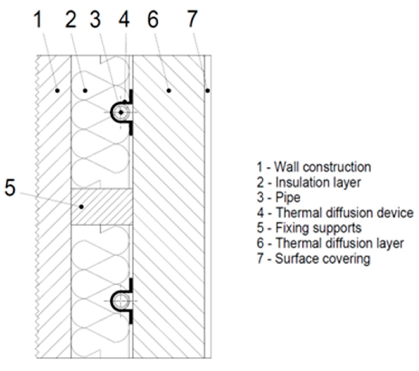
Figure 1. Wall system with pipes embedded in an insulation layer with thermal diffusion devices, type B [98,99,100,101,102,103].
Coatings 15 00756 g001
Figure 2. Three-dimensional mathematical–physical model of a building envelope fragment with ATP. [Authors]. Legend: qi—radiant flux density towards the interior (W/m2); qe—radiant flux density towards the exterior (W/m2); θi—inside air temperature (°C); θe—outside air temperature (°C); θpi—interior surface temperature (°C); θpe—exterior surface temperature (°C); L—an axial distance of pipes (m); d—pipe diameter (m); Λa—thermal permeability of the layer in front of the pipes toward the interior (W/(m2.K)); Λb—thermal permeability of the layer behind the pipes toward the exterior (W/(m2.K)); Λd—thermal conductivity of the pipe material (W/(m2.K)); θd—the average temperature of the structure in the axis of the pipes (°C); θm—average heating water temperature (°C); hi—heat transfer coefficient toward the interior (W/(m2.K)); he—heat transfer coefficient toward the exterior (W/(m2.K)); a—thickness of the layer in front of the pipes (m); b—thickness of the layer behind the pipes (m).
Coatings 15 00756 g002
Figure 3. A simplified mathematical–physical model of the lightweight building envelope of modular and panelised buildings. [Authors] Legend: d—total thickness of the construction (mm); qi—radiant heat flux density directed towards the interior (W/m2); qeradiant heat flux density directed towards the exterior (W/m2); θm—temperature within the construction (°C); ATP—active thermal protection. Boundary conditions: θTL—temperature of the heat carrier fluid (6 °C); θi—interior temperature (20 °C); θe—exterior temperature (−11 °C); hi—heat transfer coefficient on the inner surface horizontally (8 W/(m2.K)); he—heat transfer coefficient on the outer surface during the winter period (23 W/(m2.K)). Parameters: L—axial distance of ATP pipes (mm); DN—pipe dimension; i.e.; Øe—outer diameter of the pipe (mm) and Øi—inner diameter of the pipe (mm); dTI—thickness of thermal insulation (mm); Q—heat/cold (kWh) delivered to the pipe layer by the heat carrier fluid at temperature θ (°C) over time t (s); layer with ATP.
Coatings 15 00756 g003
Figure 4. (a) Temperature profile in the construction during the winter period, (b) Temperature profile in the construction during the summer period [Authors]. Legend: i—interior; e—exterior; dTIthickness of thermal insulation (mm).
Coatings 15 00756 g004
Figure 5. Principal representation of the thermal barrier (TB) function [Authors]. Legend: i—interior; e—exterior; x—thickness of thermal insulation (mm); d—total thickness of the construction (mm); θi—interior temperature (20 °C); θe—exterior temperature (−11 °C); θATP—mean temperature in the ATP layer (°C); ΦATP—heat output (W).
Coatings 15 00756 g005
Figure 6. Principle of static and dynamic thermal resistance of building structures, Authors [20]. (a) Mathematical–physical model for calculation of static thermal resistance, (b) Mathematical–physical model for calculation of dynamic thermal resistance.
Coatings 15 00756 g006
Figure 7. (a) Steady-State Thermal model schematic in ANSYS, (b) Parametric model geometry in DesignModeler [Authors].
Coatings 15 00756 g007
Figure 8. Model of the construction fragment with generated mesh [Authors].
Coatings 15 00756 g008
Figure 9. Dependence of the mean temperature θm,ATP (°C) in the ATP layer and the dynamic thermal resistance of the building structure RDYN ((m2.K)/W), when the thermal insulation thickness is changed from 50 to 1000 mm in the heating period at internal temperature of θi = +20 °C and external temperature is θe = −11 °C [Authors].
Coatings 15 00756 g009
Figure 10. Dependence of the mean temperature θm,ATP (°C) in the ATP layer and the dynamic thermal resistance of the building structure RDYN ((m2.K)/W) for a change in thermal insulation thickness from 50 to 1000 mm in the cooling season at an internal temperature of θi = +26 °C and an external temperature of θe = +32 °C, or θi = +20 °C and an external temperature of θe = +36 °C. [Authors].
Coatings 15 00756 g010
Figure 11. Overall temperature distribution in the fragment with ATP [Authors].
Coatings 15 00756 g011
Table 1. Thermal-technical properties of the construction [Authors].
Material NameThicknessDensityThermal Conductivity CoefficientSpecific Heat Capacity
Symboldρλc
Unitmkg/m3W/(m·K)J/(kg·K)
1.Gypsum board0.0158400.142960
2.Lat0.056000.222510
3.Thermal insulation
(glass wool)
0.140210.033840
4.Gypsum board0.0158400.142960
5.Adhesive plaster0.00513000.8001020
6.Thermal insulation (EPS)dTI *1000.0351020
7.Reinforcing plaster0.00313000.8001020
8.Exterior plaster0.00218000.800920
9.Pe-Xa pipee x Øi) **9200.3501470
* Parameter: thickness of thermal insulation (dTI). ** Parameter of pipe: outer diameter of pipe (Øe) and inner diameter of pipe (Øi).
Table 2. Changing parameters in the simulation [Authors].
Parameter NameSymbolUnit in ANSYS
1.Thickness of Thermal InsulationdTIm
2.Outer Diameter of PipeØem
3.Inner Diameter of PipeØim
4.Axial Distance of the ATP PipesLm
Table 3. Results of the parametric study for the heating period [Authors].
Thermal insulation thickness from the ATP layer to the exterior
dATP-TI_ext (mm)
5065751001251501752002252503004005007501000
Temperature in the ATP layer θATP (°C)−3.63−2.10−1.190.802.443.835.016.036.927.709.0210.9612.3114.4115.61
Total thermal resistance
RT ((m2·K)/W)
6.206.636.927.638.349.069.7710.4911.2011.9213.3416.2019.0626.2033.34
Total heat transfer coefficient
UT (W/(m2·K))
0.1610.1510.1450.1310.1200.1100.1020.0950.0890.0840.0750.0620.0520.0380.030
Table 4. Results of the parametric study for the cooling period [Authors].
Thermal insulation thickness from the ATP layer to the exterior
dATP-TI_ext (mm)
5065751001251501752002252503004005007501000
Temperature in the ATP layer
θATP (°C),
θi = +20 °C,
θe = +36 °C
32.1931.4130.9429.9129.0628.3527.7427.2126.7526.3525.6724.6723.9722.8922.27
Temperature in the ATP layer
θATP (°C),
θi = +26 °C,
θe = +32 °C
30.5730.2830.129.7229.429.1328.928.728.5328.3828.1327.7527.4927.0826.85
Total thermal resistance
RT ((m2·K)/W)
6.206.636.927.638.349.069.7710.4911.2011.9213.3416.2019.0626.2033.34
Total heat transfer coefficient
UT (W/(m2·K))
0.1610.1510.1450.1310.1200.1100.1020.0950.0890.0840.0750.0620.0520.0380.030
Table 5. Summary of simulation results (pipe Ø16 × 1.5 mm) [Authors].
Thermal Insulation ThicknessAxial Distance of the PipeAverage Total Radiant Flux DensityRadiant Flux Density on the Outer Surface of the PipeRadiant Flux Density on the Inner Surface of the PipeAverage Total Temperature in the StructureMinimum Temperature at the Pipe JunctionMaximum Temperature at the Pipe Junction
dTI (m)L (m)q (W/m2)qext (W/m2)qint (W/m2)θ (°C)θm-min (°C)θm-max (°C)
1.0.100.104.006.297.958.515.755.98
2.0.100.154.108.5310.788.315.215.87
3.0.100.204.1610.2912.968.124.635.79
4.0.150.103.374.675.837.186.076.10
5.0.150.153.374.325.447.095.886.05
6.0.150.203.384.085.157.015.666.01
7.0.200.102.974.395.466.096.146.23
8.0.200.152.954.425.496.096.146.23
9.0.200.202.954.405.456.066.136.21
Table 6. Simulation results of the total radiant heat flux (pipe Ø16 × 1.5 mm) [Authors].
Axial distance of the pipe
100 mm150 mm200 mm
Thickness of thermal insulation100 mmCoatings 15 00756 i001Coatings 15 00756 i002Coatings 15 00756 i003
150 mmCoatings 15 00756 i004Coatings 15 00756 i005Coatings 15 00756 i006
200 mmCoatings 15 00756 i007Coatings 15 00756 i008Coatings 15 00756 i009
Table 7. Simulation results of temperature distribution in the structure (pipe Ø16 × 1.5 mm) [Authors].
Axial distance of the pipe
100 mm150 mm200 mm
Thickness of thermal insulation100 mmCoatings 15 00756 i010Coatings 15 00756 i011Coatings 15 00756 i012
150 mmCoatings 15 00756 i013Coatings 15 00756 i014Coatings 15 00756 i015
200 mmCoatings 15 00756 i016Coatings 15 00756 i017Coatings 15 00756 i018
Disclaimer/Publisher’s Note: The statements, opinions and data contained in all publications are solely those of the individual author(s) and contributor(s) and not of MDPI and/or the editor(s). MDPI and/or the editor(s) disclaim responsibility for any injury to people or property resulting from any ideas, methods, instructions or products referred to in the content.