Article

Coating of Cubic Boron Nitride Powder with TiN in a Rotating Drum via Gas Phase Processes

Fraunhofer Institute for Ceramic Technologies and Systems IKTS, 01277 Dresden, Germany
*
Author to whom correspondence should be addressed.
Coatings 2025, 15(6), 711; https://doi.org/10.3390/coatings15060711
Submission received: 9 May 2025 / Revised: 6 June 2025 / Accepted: 11 June 2025 / Published: 13 June 2025

Abstract

To improve the performance of superhard ceramic composites, this study aims to develop a dense, phase-pure, and uniform TiN coating on cubic boron nitride (cBN) particles with a target thickness of at least 150 nm. TiN coatings were applied using atomic layer deposition (ALD) alone, as well as a combined ALD/chemical vapor deposition (CVD) process. While ALD produced uniform and dense coatings, the thickness remained below 50 nm. The combined ALD/CVD approach achieved greater thicknesses up to 500 nm, though coating homogeneity remained a challenge. Optimization efforts, including increased ALD cycles and reduced CVD pressure, led to improved coating uniformity, with 25%–30% of particles coated to thicknesses ≥ 80 nm. Structural analysis confirmed dense, pore-free TiN1−x layers for all synthesized powders. In contrast, the commercial reference powder showed a non-uniform, multiphase coating (α − Ti, Ti2N, and TiN0.53) with defects. While the ALD/CVD powders exhibited better phase purity than the commercial sample, further optimization is needed to achieve consistent coatings above 150 nm. These results suggest the ALD/CVD route is promising for producing coatings suitable for use in ceramic matrix composites.

Graphical Abstract

1. Introduction

Superhard materials play a significant role in modern industrial applications, particularly in fields such as cutting material in mechanical and plant engineering or as bearings and seals where extremely high demands are placed on wear resistance, hardness, and thermal stability [1,2,3,4]. Cubic boron nitride (cBN) is widely used for its outstanding properties, such as its low thermal expansion and chemical stability and high elastic modulus, thermal conductivity, and hardness [5,6,7,8,9]. As a result, efforts have been made to incorporate cBN into structural ceramics like Al2O3 [10,11,12,13,14,15,16], SiAlON, [13,17,18,19,20,21,22], and Si3N4 [22], as well as WC-Co/(W,Ti,Ta)C-based hard metals and cermets [13,23]. Traditional production methods for cBN in the form of polycrystalline cubic boron nitride (PcBN) require high pressures (approx. 14 GPa) and temperatures (approx. 1300–2000 °C) [24,25]. The preparation of superhard ceramic composites is increasingly carried out using low-pressure techniques such as Spark Plasma Sintering (SPS) to reduce production costs and achieve higher geometric flexibility. However, it has been observed that the integration of cBN by using low pressure is often accompanied by the transformation of cBN into hexagonal boron nitride (hBN) at sintering temperatures, weakening the interface between the matrix material and cBN [13,17,18,22]. This phenomenon leads to a deterioration in the material’s mechanical properties, like elastic modulus [12], hardness [11,17,20,22,26], fracture toughness [10,15,22,26], and tribological properties [15,22].
To inhibit the transformation of cBN and improve the bonding between cBN and the matrix, coatings of Ni [14,27,28], SiO2 [29], Al [30], Ti [22], TiN [31,32], and Al2O3 [23] on the cBN are utilized in the literature. In these cases, the coating plays a crucial role in strengthening the interface between cBN and the surrounding matrix or secondary phases, significantly influencing the mechanical and tribological properties of the resulting composites. However, these properties are only improved if the coating maintains its chemical and physical stability throughout the sintering process. To achieve this, it is essential to produce coatings that are uniform, dense, and sufficiently thick. In [22] a titanium coating on cBN was applied to protect the cBN particles from the oxynitride liquid phase present in SiAlON composites. During the process, Ti was transformed into TiN, so that the formation of hBN could not be fully suppressed.
TiN is considered to be a highly promising coating material for Al2O3 and Si3N4 ceramic matrices due to its phase stability when applied to cBN and sintered at low pressures and fast heating regimes. Furthermore, TiN can be deposited by both CVD and ALD using the same titanium precursor (TiCl4), which is leveraged in this study. Research has shown that TiN effectively inhibits the transformation of cBN into hBN at temperatures up to 1650 °C [26,31]. In [31] the thermal stability of cBN powder coated with TiN was examined, revealing that TiN does not react with cBN in a nitrogen atmosphere at ambient pressure, even up to 1600 °C.
Several reports have demonstrated the preparation of a TiN coating on cBN powder [33,34,35,36]. However, achieving a uniform, phase-pure, and precisely controlled coating with a minimum thickness of approximately 100 nm remains a significant challenge. A recurring challenge in the synthesis of TiN coatings lies in either insufficient layer thickness < 100 nm [35,36], avoiding the formation of discontinuous or nanoparticulate morphologies [36], preparation associated with high costs at high temperature and high pressure (HPHT) (in the respective study the layer thickness of the TiN coating was not determined) [33], or compositional inhomogeneities (for example, high oxygen content) arising from the broad homogeneity range of TiN [34,35,36]. As a representative example in [35], Ti layers can be deposited onto cBN substrates using the decomposition of Ti salts containing halides. The layer can be subsequently converted to TiN via reaction with nitrogen. However, it is accompanied by reaction with the cBN powder and beside TiN TiB2 can also be formed. Also, remains of the starting salts can be incorporated into the layer. Additionally, it is not a classical CVD process.
Conversely, a gas phase process is suitable for producing TiN coatings on powders. To produce homogeneous coatings, it is necessary to ensure ideal contact between the powder surface and the gaseous precursors. This requires the powder to be in movement. There are several ways to agitate fine powders in a coating process in the gas phase: (1) a fluidized bed, (2) a rotating drum, or (3) a vibrating bed. Atomic layer deposition (ALD) provides a coating method to deposit ultra-thin films with thickness control at the atomic scale. It is based on chemisorption using sequential self-limiting surface reactions of gaseous precursors and thus it is considered as a variety of the chemical vapor deposition (CVD) technique. In contrast to the CVD technique, ALD does not run in a continuous mode but in cycles and half reactions. The coating material is typically achieved by using two precursors (A and B) reacting individually on the substrate surface and separated by a purging step usually performed with inert gases. The sequence created in this manner of “half-reaction A—purge; half-reaction B—purge” represents a so-called ALD cycle. This procedure can be considered as an optimization between precursor utilization and the time needed to reach the desired thickness, which is proportionately connected to the number of ALD cycles (growth per cycle = GPC). With these properties of the ALD coating process, it is considered as the most appropriate thin film method to deposit uniform and homogeneous ultra-thin films on high-aspect-ratio substrates or powders even down to submicron- and nano-scale particle size.
The goal of this research is to apply a phase-pure, homogenous TiN coating with proper adhesion to cBN, thereby enhancing its compatibility and performance when integrated into superhard ceramic composites.

2. Materials and Methods

As a substrate for the coating, two cBN grades (V-cBN-MB20 and V-cBN-C41) with a grain size of 20 μm were used. Both powders have a similar grain size and impurities (Supplementary Materials). However, the V-cBN-C41 has shown in certain applications superior thermal stability (determined by the supplier; the exact methods are not publicly available), which makes it more suitable for incorporation into a ceramic matrix. Therefore, mostly V-cBN-C41 was used. Nevertheless, no clear differences between the powders V-cBN-MB20 and V-cBN-C41 were found in this research. For comparison of the developed TiN coatings against state-of-the-art commercial coated cBN powder, the coated cBN powder BT4 (Table 1) was also analyzed in this study. All three powders, uncoated cBN powders V-cBN-MB20 and V-cBN-C41 and coated cBN powder BT4, were supplied by the company vdiamant (Vollstädt Diamant GmbH, Seddiner See, Germany). The chemical analysis of the uncoated cBN powders was performed using X-ray fluorescence analysis (XRF) and hot gas extraction (HGE). XRF (Bruker S8 Tiger, Bruker AXS, Karlsruhe, Germany) was used to investigate metallic impurities. HGE was employed to measure the oxygen content of the cBN powder with a LECO ONH 836 elemental analyzer (Laboratory Equipment Company, St. Joseph, MI, USA). The oxygen fraction was quantified through infrared (IR) absorption.
For coating cBN particles a tubular hot-walled reactor that can combine ALD and CVD processes was modified to use a rotating drum. The hot-walled reactor consists of an Inconel tube, which was protected against the corrosive atmosphere by an inner tube made of quartz glass. The powder was put into a graphite drum, which was connected to the carrier tube. This carrier tube was connected to a rotary feedthrough and was driven by an electric motor outside of the reactor. A rotating speed of 15 to 48 rpm could be realized. The reactor is encased by an electrical clamshell-type furnace and is designed for process temperatures of up to 1050 °C, which are necessary for CVD processes. As ALD processes are often slow, a combination of ALD and CVD processes was also used to coat cBN particles. For the combination of both processes in a first coating step, a TiN ALD layer was deposited at 420 °C to ensure a homogenous coating of the particle surface. Afterwards the process regime was switched to CVD mode, which means a substrate temperature of 950 °C was adjusted with the appropriate gas flows. For both coating methods, TiCl4 was used as the titanium precursor and NH3 acted as the nitrogen precursor in the ALD process, whereas N2 was used as the nitrogen precursor in the CVD process. The utilized gases had a purity of 99.995% for NH3 and 99.9% for H2 and N2, which were further cleaned by an Oxisorb cartridge (Air Liquide Deutschland GmbH, Düsseldorf, Germany). The liquid TiCl4 evaporated by a bubbler system had a purity of about 99%.
The effort of developing a suitable TiN coating on the cBN included the coated powder BT1, which was already previously analyzed by Hering et al. [31] (powder BT) with respect to its thermal stability. In this study [31], the TiN coating with a thickness < 50 nm demonstrated recrystallization after heat treatment at 1600 °C for 60 min in a nitrogen atmosphere (ambient pressure). Consequently, a thicker coating is desired to ensure enhanced stability during sintering. The design of coating experiments is depicted in Table 1.
To evaluate the thermal properties of the powders BT3 (with a pure TiN coating) and BT4 (characterized by excess Ti in the coating, including TiN1−x and Ti2N phases; see Section 3), both powders were subjected to TGA treatment at 1400 °C under flowing nitrogen (5 L/h) in a graphite crucible. These samples were also analyzed as follows.
The TiN-coated cBN powders BT1–BT4 were characterized by detailed investigation of both the particle surface and the cross-section (for cross-section analysis powders BT3 (TGA) and BT4 (TGA) were also used). For the surface analysis the TiN-coated particles were dispersed onto a small holder pre-coated with a carbon film. Additionally, the samples were coated with a thin layer of carbon. For the analyzation of the samples, a field emission scanning electron microscope Crossbeam 550 (FESEM; Zeiss Ltd., Oberkochen, Germany) with a BSE (backscattered electron) detector for material contrast and an SE (secondary electron) detector (Zeiss Ltd., Oberkochen, Germany) for topography contrast was used. It should be noted that, in the case of very thin coatings (<100 nm), qualitative differences in coating thicknesses can be detected in surface images using backscattered electron (BSE) contrast at accelerating voltages below 2 kV. Therefore, the statistics of the coating density and thickness were estimated by using low accelerating voltages (0.7–2 kV). For a more precise determination of the layer thickness of the coating, cross-sections of the respective powders were analyzed. The cross-section was prepared by infiltrating the particles with epoxy resin and subsequently preparing them artifact-free through ion beam cutting [37]. Subsequently, the samples were analyzed in the FESEM using the BSE detector. The layer thickness of the powders was estimated based on the observed minimum and maximum thickness of the respective cross-section that belongs to the coating.
X-Ray diffraction (XRD) analysis (D8 Advance, Bruker AXS, Karlsruhe, Germany) was conducted with CuKα radiation (two-theta range of 10–100° 2θ with a step size of 0.02° 2θ) to determine the phase composition of the coated powders. Phase identification was carried out using the software DIFFRAC.EVA V7 (Bruker AXS, Karlsruhe, Germany) and the reference data from the Powder Diffraction File (PDF), including α -Ti (PDF 01-077-3482), TiN (PDF 00-038-1420), TiN0.76 (PDF 01-087-0626), TiN0.53 (PDF 01-085-5172), Ti2N (PDF 01-076-0198), and cBN (PDF 00-035-1365). The phase content of the TiN-coated cBN powders was analyzed using Rietveld refinement with the TOPAS V5 software (Bruker AXS). For this analysis, structural information from α -Ti (ICSD 653278), TiN (ICSD 64905), TiN0.76 (ICSD 64902), TiN0.53 (ICSD 197544), Ti2N (ICSD 33715), and cBN (ICSD 42002) was utilized.

3. Results

In the following, the coated powders (Table 1) are examined by analyzing the surface (Section 3.1) and the cross-section (Section 3.2) of the respective powders in detail. After that the phase composition of the titanium nitride phases are evaluated (Section 3.3).

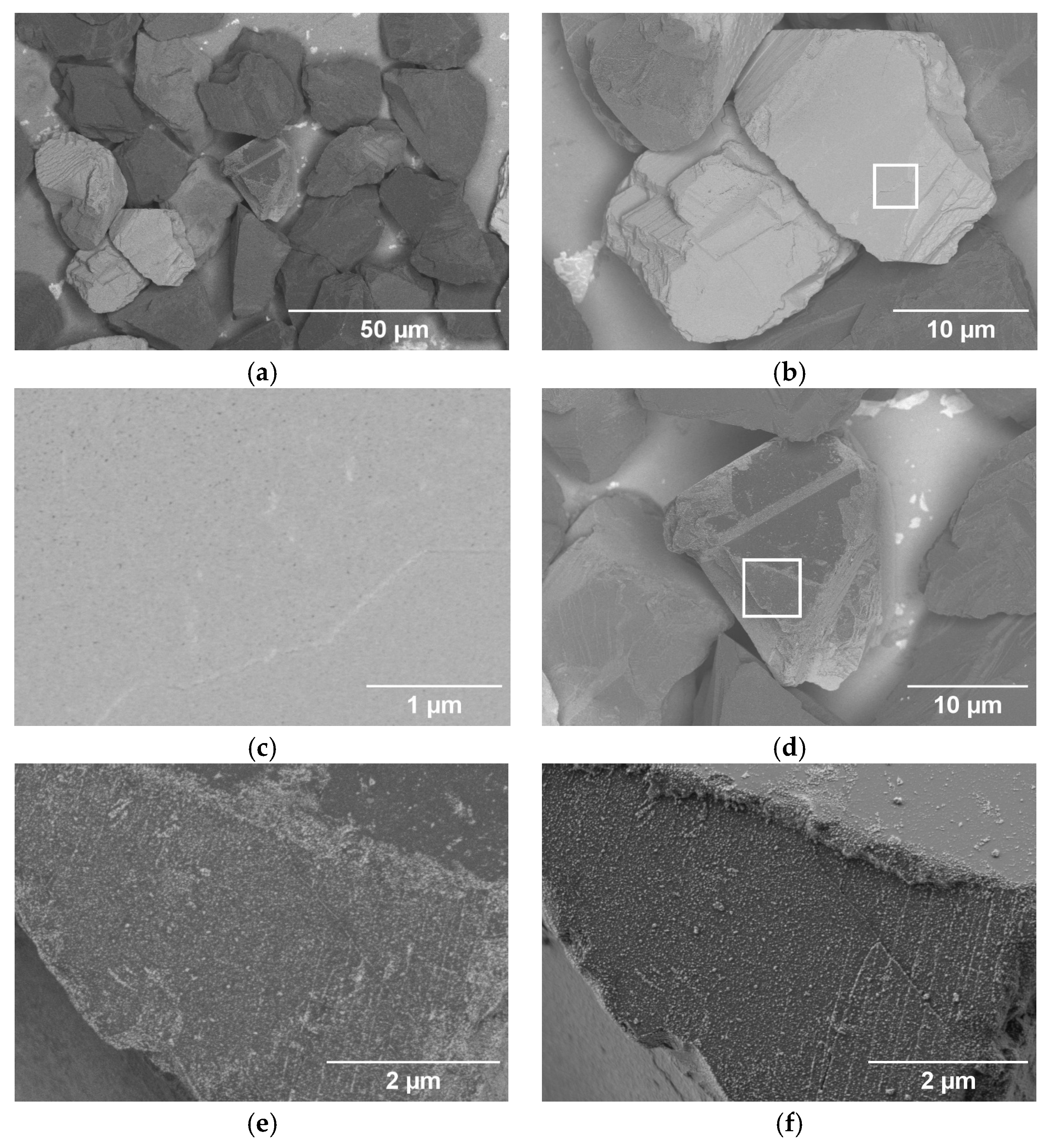
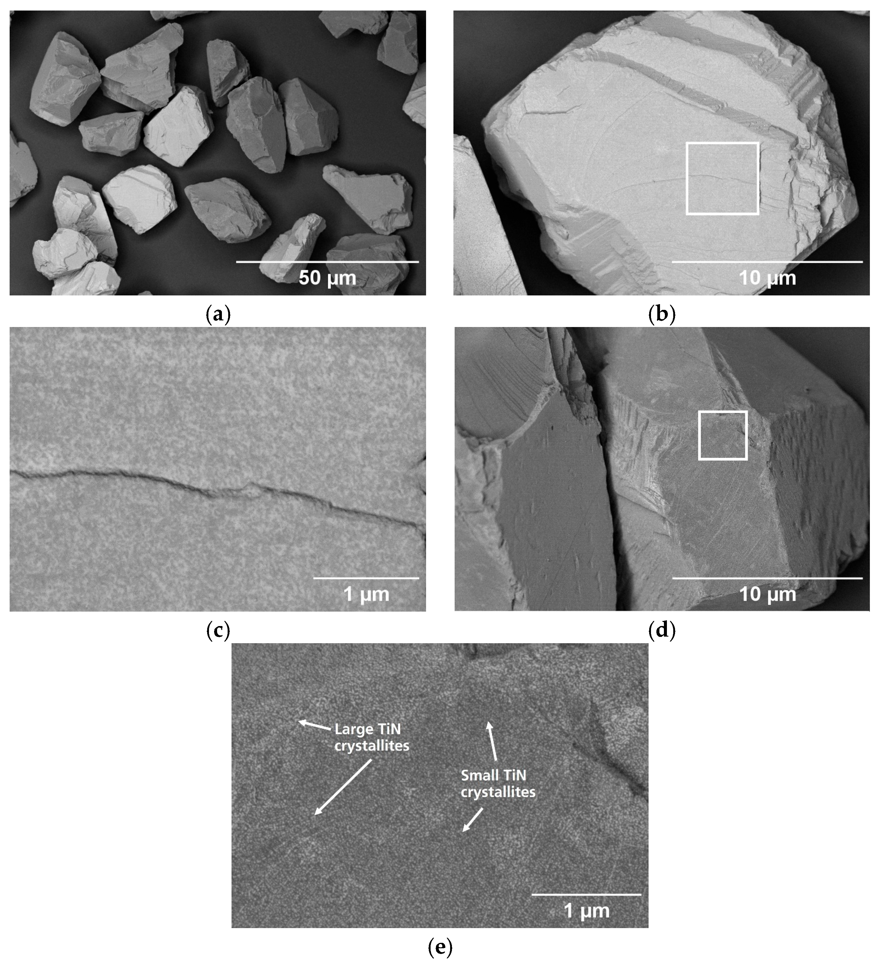
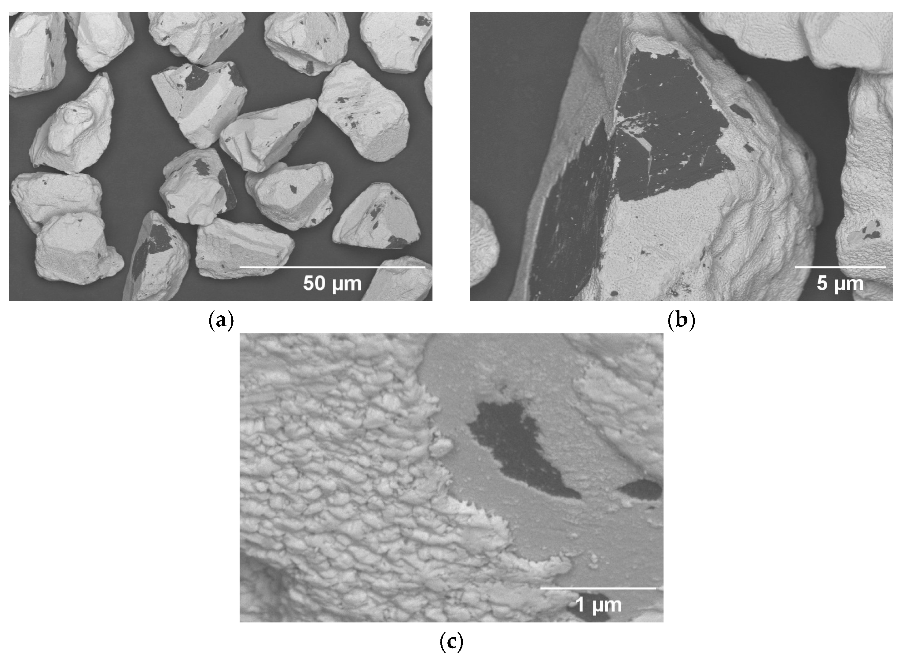
3.1. Particle Surface Characterization

At first, the TiN was deposited on the cBN using only the ALD process and the rotating drum (see Section 2) to achieve a high-quality coating. The surface of the coated cBN particles of experiment BT1 (Figure 1) shows that a TiN coating is present on nearly all cBN grains (Figure 1a). The coating uniformly covers the whole particle and appears dense (Figure 1b,c). Only a few particles exhibit a partly damaged coating (Figure 1d) with material contrast. The same damage is visible via topography contrast (Figure 1e) and is likely caused by contact with another cBN particle during the coating process [31].
The powder BT2 was prepared by a combined ALD/CVD approach to increase the layer thickness of the coating. In contrast to the findings for powder BT1, only approximately 15%–20% of the particles exhibit a thick coating (approx. 100–500 nm; Figure 2a) and layer thickness estimation (Section 3.3). The use of a low accelerating voltage and the BSE detector allows the different brightnesses to be directly correlated with the thickness of the coating. The large variation in brightness is an indication of the wide variation in thickness (20–500 nm). However, it gives no absolute values of the coating thickness. At least for the darker grains, the signal comes from both the coating and the underlying cBN. This indicates a very thin coating. The higher magnification of the particles (Figure 2b,c) reveals that the coatings of these particles are dense. Beside this there exist particles with only partial coating (Figure 2d–f). It is visible that TiN precipitates have only formed locally. This becomes more evident by comparing the micrographs detected in the different modes (Figure 2d,f).
The surfaces of the powder BT3 exhibit different characteristics. The images (Figure 3a–c) reveal that 25%–35% of particles exhibit a dense and thick coating. However, some particles exhibit only local coating, while others show a very thin layer. This variation is evident from the different gray levels of the particles (Figure 3) and the higher-magnification images in Figure 3d,e. Regions containing both smaller and larger TiN crystallites can be observed on the surface (Figure 3e).
The surface of the coated cBN particles of the commercial coated cBN powder BT4 (Figure 4) reveals that, unlike BT2 and BT3, the coating is homogeneously distributed across all particles (Figure 4a). Numerous artifacts and areas without coating are visible on the surfaces. Closer inspection at higher magnification (Figure 4b,c) reveals that the coating consists of two layers: a thicker outer layer and a thinner inner layer on top of the cBN.

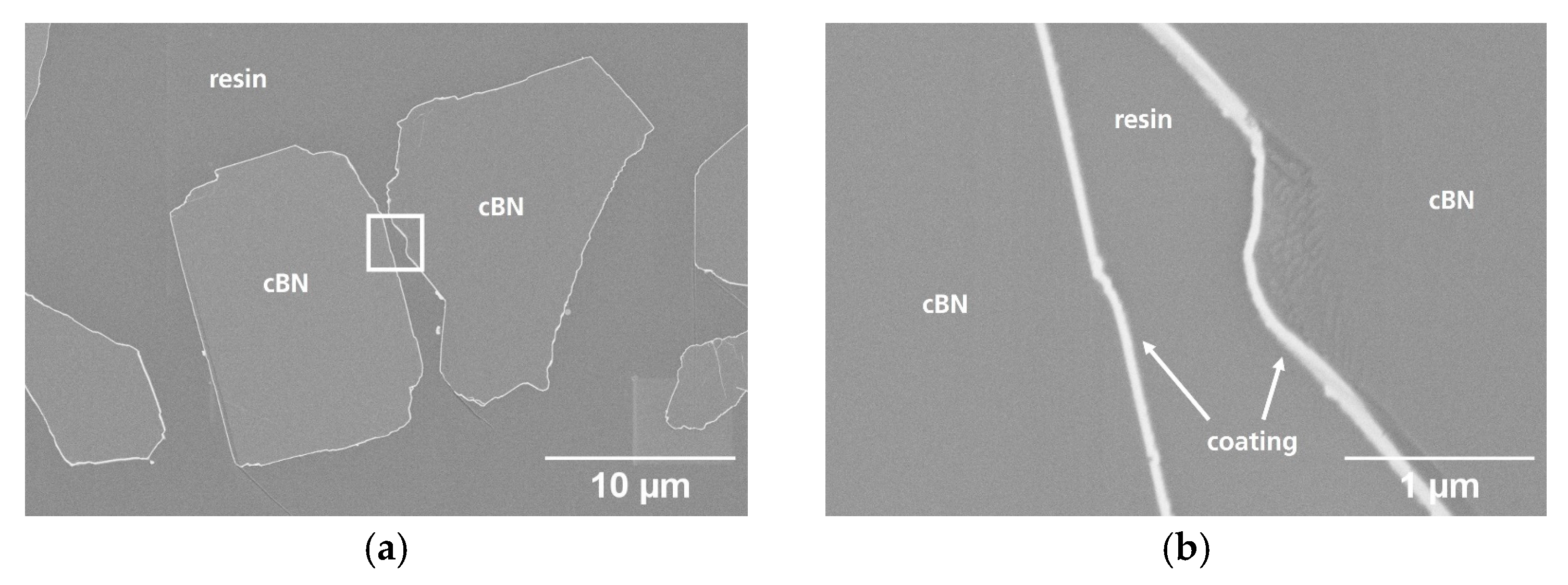
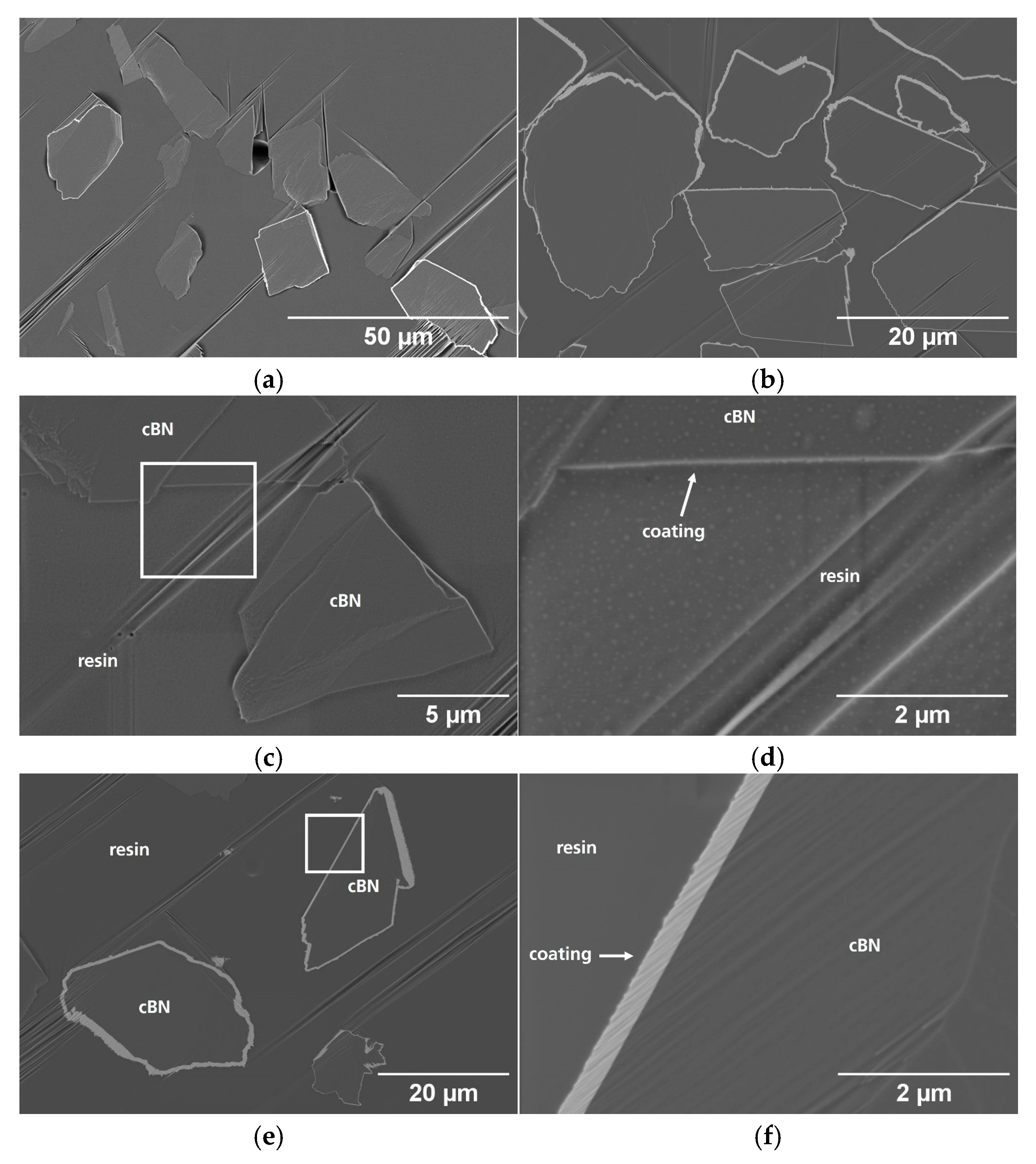
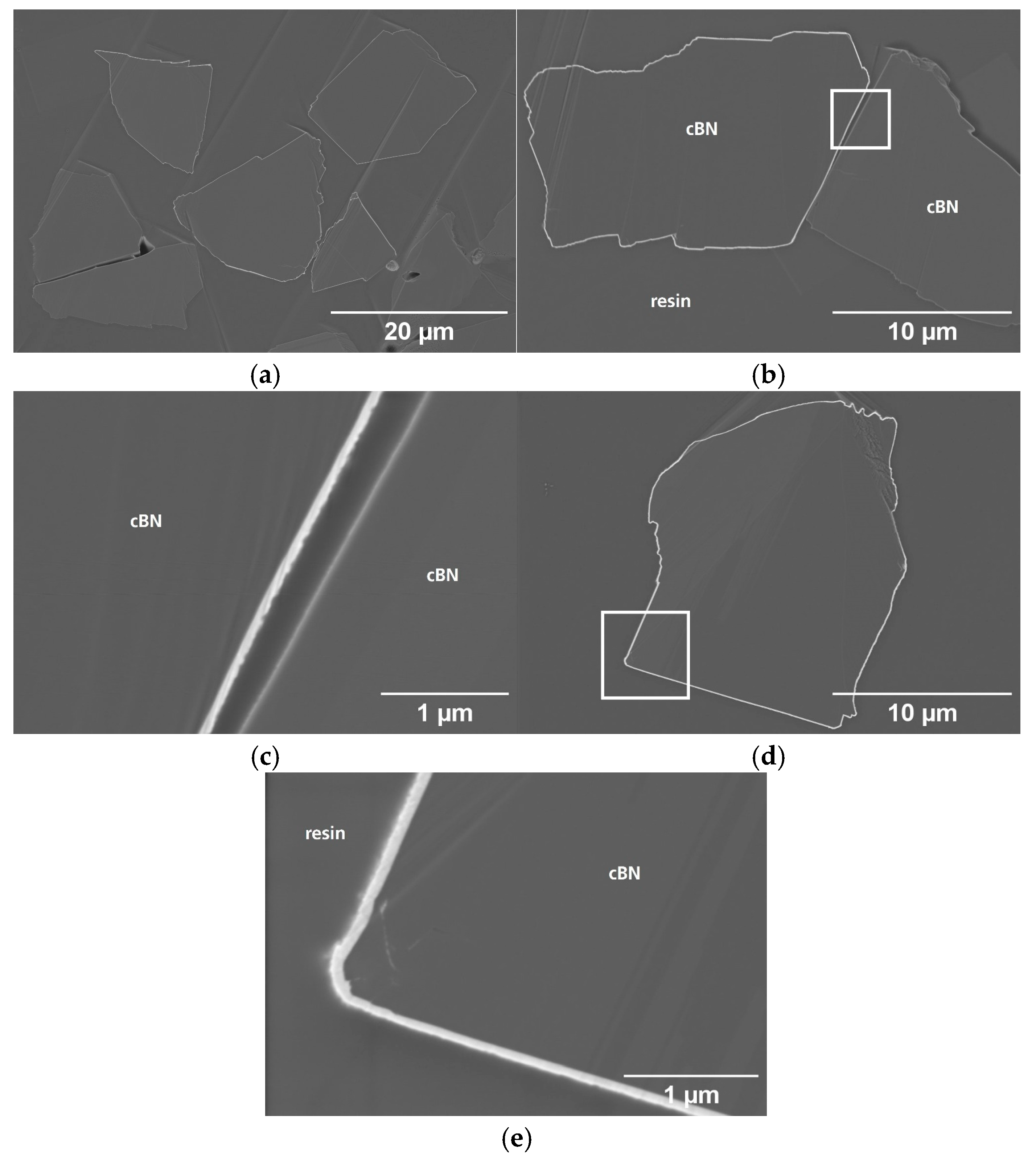
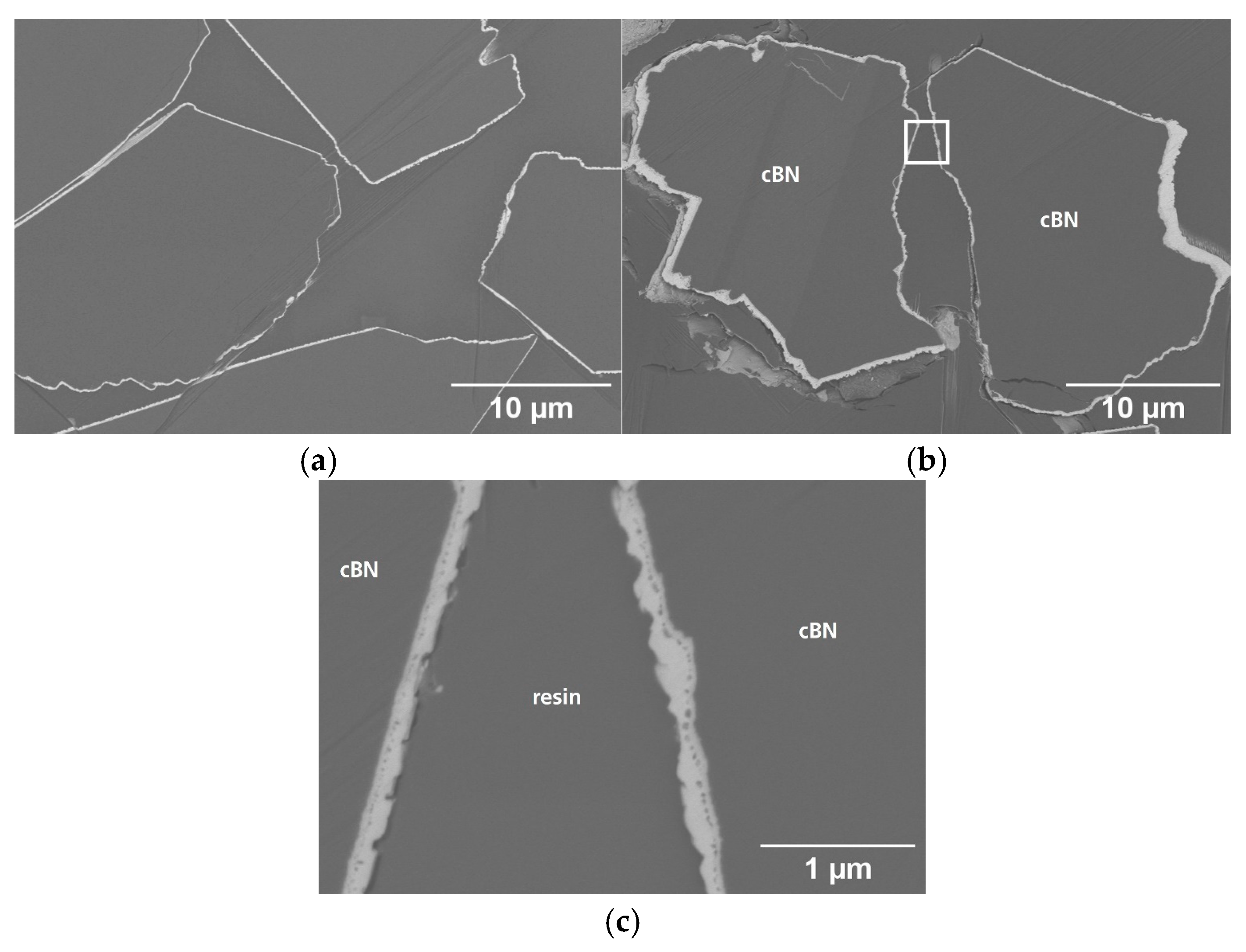
3.2. Particle Cross-Section Analysis

The cross-sections of the coated particles of BT1 (Figure 5) show that the coating (white area) is homogenous across the particle surface, as was previously concluded from the surface analysis (Figure 1). The coating is dense and uniform, with a thickness of approximately 40–50 nm (Figure 5b).
However, since a greater layer thickness is desirable for the application of coated particles in superhard ceramic composites, a combined ALD/CVD process was employed to achieve this in experiments BT2 and BT3, which are analyzed in the following.
Powder BT2 possesses thicker (Figure 6b) and thinner coatings, as previously described (Figure 2). A detailed view of the thinner coating on the cBN (Figure 6c,d) reveals the presence of a coating with a thickness ranging from 20 to 40 nm. In contrast, the thicker coating (Figure 6e,f) demonstrates that the coating can reach thicknesses of up to 500 nm in certain surface areas. It is evident that the coating is dense, similar to the BT1 coating. Consequently, it is desirable to increase the number of adequately coated particles, with a targeted minimum coating thickness of 100 nm. For this reason, the coating process was optimized during the preparation of powder BT3 (Table 1).
The TiN coating of the cBN powder BT3 in Figure 7 also exhibits variations in thickness. Here, both thinner and thicker coatings are present (Figure 7a). A comparison between these thicknesses is provided (Figure 7b,c), revealing a range of approximately 20–100 nm. A closer examination (Figure 7d,e) demonstrates that the coating is dense.
A significant difference in coating characteristics is observed for the commercial cBN powder BT4 (Figure 8). The thickness of the coating seems more uniform in comparison to the coated cBN powders BT1–3 (Figure 8a). However certain areas exhibit thicknesses of up to 1 µm (Figure 8b), although the overall thickness is at least around 100 nm. The surface appears rough. At higher magnification (Figure 8c), it becomes evident that the coating contains voids, possibly separating two layers of the coating, which were also observed in the surface analysis in Figure 4c.

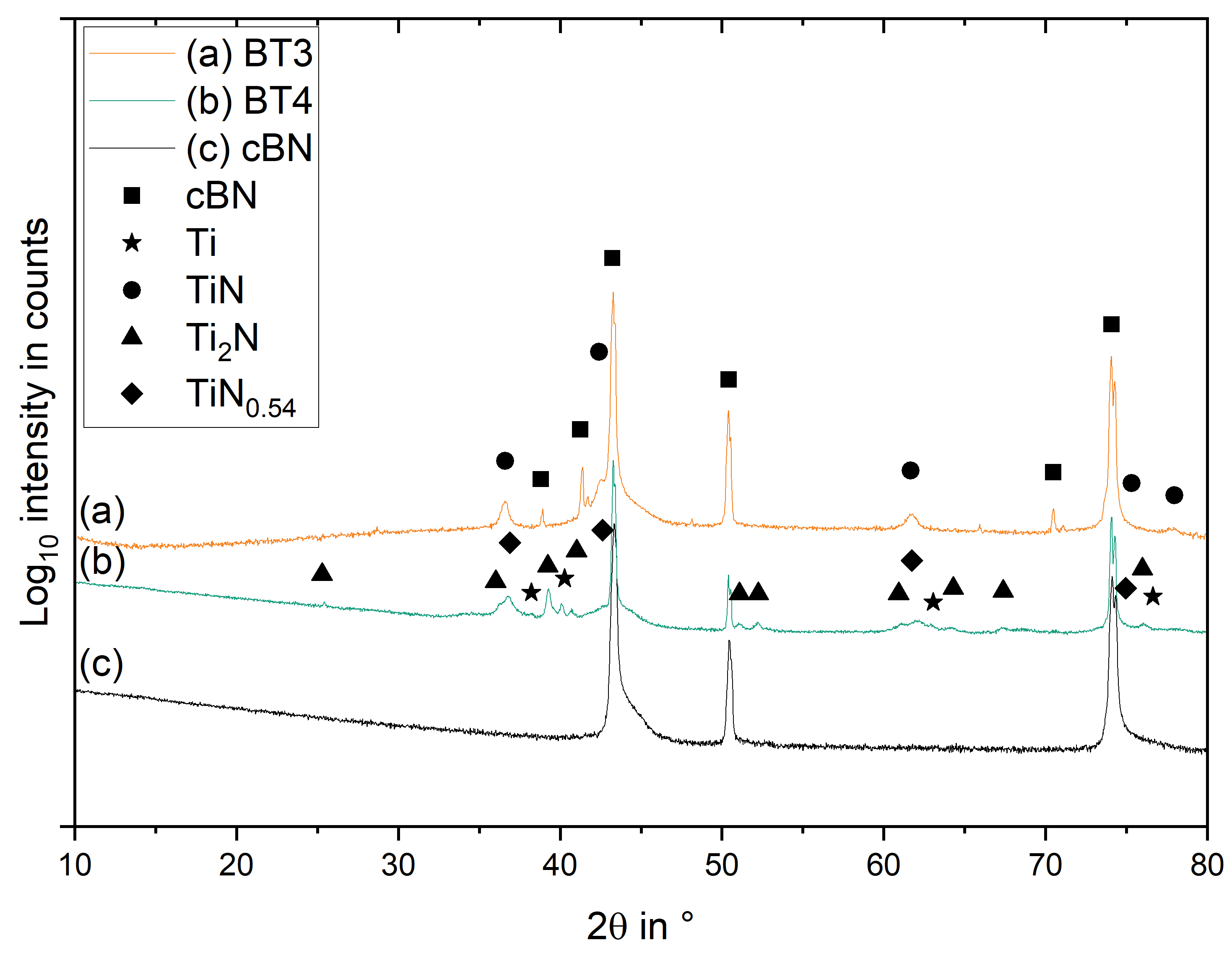
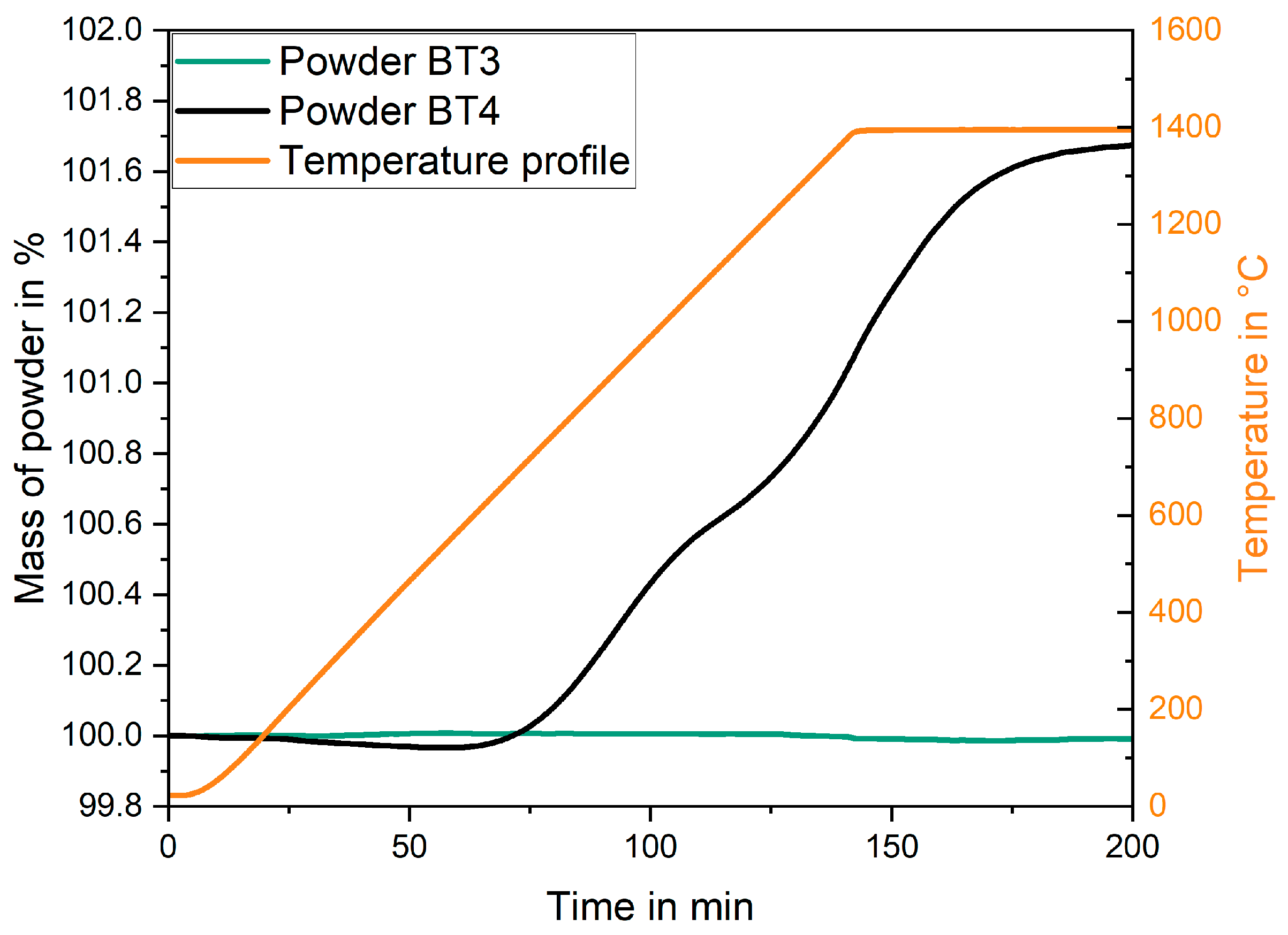
3.3. Phase Formation

To evaluate the suitability of the coated powders for use in superhard ceramic composites, it is crucial to determine the phase composition of the coatings (Table 2). For successful application, the coating should ideally consist of stoichiometric TiN (visible in XRD for BT1 and BT2 in Figure 9). It is clearly visible that, beside the cBN phase, cubic TiN is formed. However, the peaks of the TiN phase in the powders are shifted against each other. This indicates that the stoichiometry of the coating is different. The peaks of the TiN1−x phase of sample BT1 are shifted to lower angles, indicating a lower lattice parameter (Table 2). The peak positions and the lattice parameter of the TiN phase in the material BT2 correspond to the values of stoichiometric TiN. This indicates that the pure ALD process does not produce a stochiometric TiN coating, whereas the combined ALD/CVD approach significantly improves the phase purity. Additionally the half width of the TiN peaks in BT2 is lower. This implies that either the crystallite size of TiN is smaller or, alternatively, that a higher defect density has been introduced.
In the diffractograms for the BT3 and BT4 coatings (Figure 10), it is evident that BT3 exhibits a coating consisting only of TiN (which underlines that the combined ALD/CVD approach is successful in depositing a stoichiometric TiN phase), whereas the commercial powder BT4 consists, beside cBN, of Ti, Ti2N, and TiN0.54.
In the following, thermogravimetric analysis (TGA) was conducted on powders BT3 and BT4 to evaluate their thermal behavior (Figure 11).
It is evident that the BT3 powder exhibits only a negligible mass loss, whereas BT4 shows a significant mass gain of approximately 1.7 wt%. This pronounced increase can be attributed to a phase transformation occurring in the coating, which initially contains a substantial excess of titanium. During heating, the titanium and the Ti2N (Table 2) react with atmospheric nitrogen, forming stoichiometric titanium nitride. As the formation of TiN incorporates nitrogen atoms into the lattice, this reaction leads to a net increase in mass, as described by Equations (1) and (2).
x N 2 + 2 T i N 1 x 2 T i N
2 T i + N 2 2 T i N
The sharp increase in mass starting at 726.6 °C suggests a highly reactive surface and a substantial driving force for nitridation, possibly due to the high surface area and nanosized microstructure of the coating. The mass increase shows two distinct steps, one below 1020.3 °C and a second one above this temperature. These steps may be associated with the sequential nitridation of Ti and Ti2N. However, this was not investigated in detail.
After TGA measurements, the high-magnification image of powder BT3 (TGA) (Figure 12a) reveals some recrystallization in areas where the coating thickness is approximately 20–30 nm, resulting in interruptions in the otherwise continuous coating. In areas where the TiN coating has a thickness of at least 50 nm, the coating remains continuous and stable. In contrast, powder BT4 (TGA) (Figure 12b) shows recrystallization (layer thickness > 1.4 µm), defects, and a significant amount of hBN at the cBN-TiN interface and within the coating itself. This is possibly attributed to the nitridation of Ti and Ti2N (see above). On the other hand, the stoichiometric TiN phase (Figure 13) contributes to better coating stability.
These results of the TG analysis are further supported by the XRD measurement shown in Figure 14. As expected, the diffractogram of powder BT3 remains unchanged, indicating no structural transformation. In contrast, the diffractogram of powder BT4 clearly reveals the presence of TiN. Based on the calculated lattice parameter (see Table 2), the phase corresponds closely to stoichiometric TiN, with possibly a small amount of carbon incorporated into the structure (see Discussion). Additionally, the diffractogram of the BT4 powder after the TGA measurement reveals the presence of both hexagonal boron nitride (hBN) and graphite. A clear distinction between the two phases is challenging due to overlapping main reflections in the XRD pattern at similar 2θ positions (26.5 2θ).
However, in the analysis of the cross-section of the coating, evidence of hBN was found (Figure 12). Therefore, the formation of hBN is more likely. It may result from the transformation of the stoichiometry of the coating. Also, as a metastable intermediate TiB2 could be formed by the reaction of Ti with cBN. The nitridation of the latter would result in hBN and TiN.
In summary, the results of Rietveld refinement for all coated powders (Table 2) show that the variation in the lattice parameter of the TiN1−x phase indicates differences in stoichiometry. However, the exact stoichiometry cannot be directly determined from Rietveld refinement alone.
The calculated mass fractions exhibit good correlation with the observed layer thickness ranges of the coating of the powders BT1–BT4, determined in cross-sections. The only exception is that the mass fraction of TiN0.76, of 1.77 wt%, is significantly higher than the mass fraction of TiN in the BT3 powder, which is 0.85 wt%. Meanwhile, the coating layer thickness ranges from 40–50 nm for BT1 to 20 –100 nm for BT3.
For the samples subjected to TGA, powder BT3 shows only minor deviations in the mass fraction of the TiN1−x phase, which are likely due to slight variations in the XRD measurements. In contrast, powder BT4 exhibits a significantly higher mass fraction of TiN1−x (6.32 wt%), which can be attributed to the TiN formation during the TGA process (Equations (1) and (2)).
To determine the stoichiometry of the TiN1−x phases, the lattice parameters determined must be compared with literature values [38,39,40] as a function of the composition. These values show strong mutual agreement (Figure 14). As the nitrogen content in TiN1−x increases, the lattice parameter of the cubic structure also gets larger.
The lattice parameters of the fitted TiN phases of the coated cBN powders BT1, BT2, BT4 based on the above data are also listed in Table 2 and are shown in Figure 14 in comparison to the literature data. The lattice parameters of BT2 and BT3 are slightly larger than the largest value at 1.0 N/Ti (highest value of lattice parameter is 0.4241 nm (Lengauer et al. [39])). The lattice parameter of the TiN coating is 0.42503 (±0.00003) for BT2 and 0.42519 (±0.00017) for BT3. The error of the lattice parameter of BT3 is larger due to the lower phase content. The reason for the higher value of the TiN lattice parameter in BT2 and BT3 could be the incorporation of small amounts of carbon in the coating, which is further discussed in Section 4.

4. Discussion

The objective of this research was to develop a phase-pure TiN-coated cBN powder with high density, uniformity, and a coating thickness of at least 100 nm. The TiN0.84 coating on the BT1 powder, produced by the ALD process (Table 2), exhibits high density and uniformity but reaches only a thickness of <50 nm (Figure 1 and Figure 5). As previously stated, this results in recrystallization after heat treatment at 1600 °C for 60 min in a nitrogen atmosphere (ambient pressure) [31]. It must be pointed out that recrystallization itself is not necessarily detrimental, provided that the integrity of the coating is preserved. To address this, the combined ALD/CVD process was employed to increase the TiN layer thickness. For the BT2 powder, the process achieved coating thicknesses of up to 500 nm. However, the variation in thickness is quite large, from 20 nm to 500 nm. Approximately only 15%–20% of the grains exhibit a thick coating. Nevertheless, the TiN layer exhibits no porosity and a smooth surface, likely due to the initial use of ALD in the coating process. Since most of the particles have a coating thickness of approximately 15–40 nm (Figure 2 and Figure 6), an attempt was made to optimize the process (BT3) by increasing the number of ALD cycles to increase the thickness of the initial TiN layer. This should allow for improved control of the subsequent CVD process. Additionally, during the CVD process the gas pressure was reduced (28–45 mbar) to promote uniform TiN growth (Table 1). As a result, the TiN layer on the cBN grains is distributed more homogeneously, with 25%–30% of the particles exhibiting a uniform coating thickness of >80 nm (Figure 3 and Figure 7), while maintaining high density and uniformity. However, the maximum layer thickness achieved is only approximately 100 nm. This needs further optimization in future work by extending the CVD deposition time to promote further growth.
The properties of the coated BT1, BT2, and BT3 powders can be compared to those of the commercial reference powder BT4. In the latter, all particles exhibit a coating thickness of approximately 100–180 nm, but with local uncoated areas. Additionally, the coating consists of two distinct Ti-containing layers. Furthermore, the coating is a mixture of different phases. It contains α -Ti, Ti2N, and TiN0.54 (Table 2). The excess Ti in the coating may pose challenges during the sintering of ceramic composites, as these phases tend to be more reactive than a pure TiN phase. The Ti can also directly react with the cBN, forming TiB2 and TiN. However, the formation of TiB2 was not observed in the TG analysis in nitrogen. The influence of these phases on the sintering behavior will be the subject of future investigations. The comparison between the BT1–BT3 and the BT4 powder shows that the BT1–BT3 powders exhibit a higher phase homogeneity and are also free of pores. This makes them more favorable in comparison to the BT4 powder during sintering. However further work has to be performed to increase the thickness of the coating.
The determination of the stoichiometry of the TiN1−x phases was conducted by fitting the lattice parameters of the respective TiN1−x phases to literature values (Table 2, Figure 14). The lattice parameter of the TiN phase in BT2, BT3, BT3 (TGA), and BT4 (TGA) is slightly higher than the values reported in the literature for stoichiometric TiN [38,39,40] (0.4241 nm in [38]). This could be caused by internal stresses or/and by the presence of a small amount of carbon in the coating, resulting in the formation of a TiCxN1−x phase. This is plausible for powders BT1, BT2, and BT3 because the coating took place in a graphite reactor (unknown for BT4). The lattice parameter falls within the range of approximately 0.4226 nm for TiN and 0.4334 nm for TiC [41,42]. However, it is only slightly higher than the lattice parameter of TiN. These investigations show that the gradual increase in the lattice parameter of the TiCxN1−x phase as a function of the carbon content is quite consistent with Vegard’s Rule [43]. Based on the approach described in [42], the carbon stoichiometry in the TiCxN1−x phase was calculated from the measured lattice parameters, yielding x = 0.20 for powder BT2 and x = 0.24 for powders BT3 and BT3 (TGA). Due to significant measurement uncertainties for powder BT3 (Table 2), this value should be regarded as an approximate estimate. However, the TiN1−x phase, particularly for the BT4 powder, exhibits a distinct amount of nitrogen deficiency in the crystal lattice, which may be not optimal for further processing. A heat treatment of the coating of powder BT4 in nitrogen at higher temperatures result in the formation of nearly stochiometric TiN (Figure 13 and Figure 14). The coating recrystallizes and generates defects during the heat treatment (Figure 12b). This is not observed for powder BT3 (TGA), where the high phase purity of the coating ensures that it remains stable as long as the layer thickness exceeds 50 nm. Therefore, powders processed using the combined ALD/CVD approach (BT2 and BT3) seem to be the most promising for use in ceramic matrix composites.

5. Conclusions

This study investigates the morphology and phase content of TiN coatings deposited on 20 µm cBN powder using ALD and a combined ALD/CVD process. Based on the results from the coated cBN powders (Table 1), it is evident that the ALD process (BT1) alone generates dense TiN layers < 50 nm; however, to achieve higher thicknesses of coatings, long process times are necessary. The formed coating is slightly substoichiometric (TiN0.84 in BT1). A combined ALD/CVD process could produce significantly thicker coatings compared to ALD alone, while maintaining high density. The primary issue with BT2 is that only a small proportion of particles exhibited the desired thick coating. The changed deposition parameter (BT3; Table 1) however, improved the situation only gradually. Further optimization is necessary to improve the thickness of the coating.
In contrast to the coatings of the commercial powder, a stoichiometric coating is possible to achieve. Such a stoichiometric coating has a lower reactivity with respect to cBN and ceramic matrix materials.

Supplementary Materials

The following supporting information can be downloaded at https://www.mdpi.com/article/10.3390/coatings15060711/s1, Figure S1: Impurities of the cBN grades V-cBN-MB20 and V-cBN-C41; Table S1: Oxygen content of the powders B20, C41, BT3 and BT4.

Author Contributions

Conceptualization, A.-K.W., B.M., M.H. (Mathias Herrmann), and A.M.; Methodology, A.-K.W., B.M., L.M., and M.H. (Mathias Herrmann); Investigation, L.M., M.K., and S.H.; Data Curation, L.M.; Writing—Original Draft Preparation, L.M., M.K., and M.H. (Mandy Höhn); Writing—Review and Editing, A.-K.W., B.M., M.H. (Mandy Höhn), M.K., and M.H. (Mathias Herrmann); Visualization, L.M.; Supervision, A.-K.W., B.M., A.M., M.H. (Mandy Höhn), and M.H. (Mathias Herrmann); Project Administration, A.-K.W.; Funding Acquisition, A.-K.W. All authors have read and agreed to the published version of the manuscript.

Funding

This research was funded by the Deutsche Forschungsgemeinschaft (DFG), project no.429418801.

Institutional Review Board Statement

Not applicable.

Informed Consent Statement

Not applicable.

Data Availability Statement

Data are contained within the article and Supplementary Materials.

Acknowledgments

The hot gas extraction was carried out at the Fraunhofer Institut für Fertigungstechnik und Angewandte Materialforschung IFAM (Dresden, Germany). The author especially thanks Sören Höhn at the Fraunhofer IKTS for his support in sample preparation and microstructure analysis.

Conflicts of Interest

The authors declare no conflicts of interest.

Abbreviations

The following abbreviations are used in this manuscript:
ALDAtomic layer deposition
BSEsBackscattered electrons
CVDChemical vapor deposition
FESEMField emission scanning electron microscope
GPCGrowth per cycle
hBNHexagonal boron nitride
HGEHot gas extraction
PcBNPolycrystalline cubic boron nitride
PDFPowder Diffraction File
SESecondary electron
SPSSpark plasma sintering
TG(A)Thermogravimetric analysis/Thermogravimetry
XRDX-ray diffraction
XRFX-ray fluorescence analysis

References

  1. Mills, B. Recent developments in cutting tool materials. J. Mater. Process. Technol. 1996, 56, 16–23. [Google Scholar] [CrossRef]
  2. Klimenko, S.A.; Mukovoz, Y.A.; Polonsky, L.G. Cutting Tools of Superhard Materials. In Advanced Ceramic Tools for Machining Application—II; Trans Tech Publications Ltd.: Baech, Switzerland, 1995; pp. 1–66. [Google Scholar]
  3. Haines, J.; Léger, J.M.; Bocquillon, G. Synthesis and Design of Superhard Materials. Annu. Rev. Mater. Res. 2001, 31, 1–23. [Google Scholar] [CrossRef]
  4. Rizzo, A.; Goel, S.; Luisa Grilli, M.; Iglesias, R.; Jaworska, L.; Lapkovskis, V.; Novak, P.; Postolnyi, B.O.; Valerini, D. The Critical Raw Materials in Cutting Tools for Machining Applications: A Review. Materials 2020, 13, 1377. [Google Scholar] [CrossRef] [PubMed]
  5. Xu, B.; Tian, Y. Superhard materials: Recent research progress and prospects. Sci. China Mater. 2015, 58, 132–142. [Google Scholar] [CrossRef]
  6. Riedel, R. Novel Ultrahard Materials. Adv. Mater. 1994, 6, 549–560. [Google Scholar] [CrossRef]
  7. Pierson, H.O. Handbook of Carbon, Graphite, Diamond, and Fullerenes: Properties, Processing, and Applications; Noyes Publications: Park Ridge, NJ, USA, 1993. [Google Scholar]
  8. Zou, L.; Yin, J.; Huang, Y.; Zhou, M. Essential causes for tool wear of single crystal diamond in ultra-precision cutting of ferrous metals. Diam. Relat. Mater. 2018, 86, 29–40. [Google Scholar] [CrossRef]
  9. Monteiro, S.N.; Skury, A.L.D.; de Azevedo, M.G.; Bobrovnitchii, G.S. Cubic boron nitride competing with diamond as a superhard engineering material—An overview. J. Mater. Res. Technol. 2013, 2, 68–74. [Google Scholar] [CrossRef]
  10. Wu, J.; Wang, H.; Zhang, Z.; Hou, Z.; Wu, D.; Ouyang, X. Analysis of mechanical properties of Al2O3-cBN-hBN composites and identification of main influencing factors. Int. J. Appl. Ceram. Technol. 2022, 19, 3255–3266. [Google Scholar] [CrossRef]
  11. Hotta, M.; Goto, T. Effects of cubic BN addition and phase transformation on hardness of Al2O3–cubic BN composites. Ceram. Int. 2011, 37, 1453–1457. [Google Scholar] [CrossRef]
  12. Klimczyk, P.; Wyżga, P.; Cyboroń, J.; Laszkiewicz-Łukasik, J.; Podsiadło, M.; Cygan, S.; Jaworska, L. Phase stability and mechanical properties of Al2O3-cBN composites prepared via spark plasma sintering. Diam. Relat. Mater. 2020, 104, 107762. [Google Scholar] [CrossRef]
  13. Zhang, J.; Tu, R.; Goto, T. Cubic boron nitride-containing ceramic matrix composites for cutting tools. Adv. Ceram. Matrix Compos. 2014, 570–586. [Google Scholar] [CrossRef]
  14. Zhang, J.; Tu, R.; Goto, T. Spark plasma sintering of Al2O3–cBN composites facilitated by Ni nanoparticle precipitation on cBN powder by rotary chemical vapor deposition. J. Eur. Ceram. Soc. 2011, 31, 2083–2087. [Google Scholar] [CrossRef]
  15. Yaman Islak, B.; Mandal, H. Friction and wear behavior of spark plasma-sintered cBN-added Al2O3–PSZ-based composites. J. Aust. Ceram. Soc. 2017, 53, 163–172. [Google Scholar] [CrossRef]
  16. Hotta, M.; Goto, T. Densification and microstructure of Al2O3-cBN composites prepared by spark plasma sintering. J. Ceram. Soc. Jpn. 2008, 116, 744–748. [Google Scholar] [CrossRef]
  17. Garrett, J.C.; Sigalas, I.; Herrmann, M.; Olivier, E.J.; O’Connell, J.H. cBN reinforced Y-α-SiAlON composites. J. Eur. Ceram. Soc. 2013, 33, 2191–2198. [Google Scholar] [CrossRef]
  18. Garrett, J.C.; Sigalas, I.; Herrmann, M. TEM investigation of the interface formation in cubic boron nitride containing α-SiAlON composites. Ceram. Int. 2014, 40, 16169–16175. [Google Scholar] [CrossRef]
  19. Hotta, M.; Goto, T. Densification and Phase Transformation of β-SiAlON–Cubic Boron Nitride Composites Prepared by Spark Plasma Sintering. J. Am. Ceram. Soc. 2009, 92, 1684–1690. [Google Scholar] [CrossRef]
  20. Hotta, M.; Goto, T. Effect of time on microstructure and hardness of βSiAlON–cubic boron nitride composites during spark plasma sintering. Ceram. Int. 2011, 37, 521–524. [Google Scholar] [CrossRef]
  21. Ye, F.; Hou, Z.; Zhang, H.; Liu, L.; Zhou, Y. Spark plasma sintering of cBN/β-SiAlON composites. Mater. Sci. Eng. A 2010, 527, 4723–4726. [Google Scholar] [CrossRef]
  22. Wolfrum, A.-K. Verdichtung und Eigenschaften von hartstoffverstärkten Siliciumnitridwerkstoffen. Ph.D. Dissertation, Technical University of Dresden, Dresden, Germany, 2019. [Google Scholar]
  23. Yi, M.; Jing, G.; Li, D.; Xiao, G.; Chen, Z.; Zhang, J.; Wang, L.; Xu, C. Strengthening and toughening mechanism of (W,Ti,Ta)C based cermet with the addition of c-BN@Al2O3. Ceram. Int. 2021, 47, 32075–32085. [Google Scholar] [CrossRef]
  24. Zhao, M.; Kou, Z.; Zhang, Y.; Peng, B.; Wang, Y.; Wang, Z.; Yin, X.; Jiang, M.; Guan, S.; Zhang, J.; et al. Superhard transparent polycrystalline cubic boron nitride. Appl. Phys. Lett. 2021, 118, 151901. [Google Scholar] [CrossRef]
  25. Angseryd, J.; Elfwing, M.; Olsson, E.; Andrén, H.-O. Detailed microstructure of a cBN based cutting tool material. Int. J. Refract. Met. Hard Mater. 2009, 27, 249–255. [Google Scholar] [CrossRef]
  26. Hotta, M.; Goto, T. Spark plasma sintering of TiN-cubic BN composites. J. Ceram. Soc. Jpn. 2010, 118, 137–140. [Google Scholar] [CrossRef]
  27. Irshad, H.M.; Ahmed, B.A.; Ehsan, M.A.; Khan, T.I.; Laoui, T.; Yousaf, M.R.; Ibrahim, A.; Hakeem, A.S. Investigation of the structural and mechanical properties of micro-/nano-sized Al2O3 and cBN composites prepared by spark plasma sintering. Ceram. Int. 2017, 43, 10645–10653. [Google Scholar] [CrossRef]
  28. Azam, M.U.; Ahmed, B.A.; Hakeem, A.S.; Irshad, H.M.; Laoui, T.; Ehsan, M.A.; Patel, F.; Khalid, F.A. Tribological behaviour of alumina-based nanocomposites reinforced with uncoated and Ni-coated cubic boron nitride. J. Mater. Res. Technol. 2019, 8, 5066–5079. [Google Scholar] [CrossRef]
  29. Zhang, J.; Tu, R.; Goto, T. Evaluation of CVD-Deposited SiO2 as a Sintering Aid for Cubic Boron Nitride Consolidated with Alumina by Spark Plasma Sintering. J. Am. Ceram. Soc. 2012, 95, 2827–2832. [Google Scholar] [CrossRef]
  30. Chu, D.; Ma, H.; Zhang, Z.; Peng, F.; Jia, X. Synthesis and characterization of cubic boron nitride (Al)-Al2O3 composites under high pressure and high temperature conditions. Int. J. Refract. Met. Hard Mater. 2022, 106, 105876. [Google Scholar] [CrossRef]
  31. Hering, B.; Wolfrum, A.-K.; Gestrich, T.; Herrmann, M. Thermal Stability of TiN Coated Cubic Boron Nitride Powder. Materials 2021, 14, 1642. [Google Scholar] [CrossRef]
  32. Umer, M.A.; Sub, P.H.; Lee, D.J.; Ryu, H.J.; Hong, S.H. Polycrystalline cubic boron nitride sintered compacts prepared from nanocrystalline TiN coated cBN powder. Mater. Sci. Eng. A 2012, 552, 151–156. [Google Scholar] [CrossRef]
  33. Chen, D.; Liu, Z.; Fan, B.; Li, J.; Cao, W.; Wang, H.; Lu, H.; Xu, H.; Zhang, R. Synthesis and Characterization of TiN-coated Cubic Boron Nitride Powders. Int. J. Appl. Ceram. Technol. 2014, 11, 946–953. [Google Scholar] [CrossRef]
  34. Umer, M.A.; Park, H.S.; Lee, D.J.; Ryu, H.J.; Hong, S.H. A sol–gel route to nanocrystalline TiN coated cubic boron nitride particles. J. Alloys Compd. 2011, 509, 9764–9769. [Google Scholar] [CrossRef]
  35. Daoush, W.M.; Park, H.S.; Hong, S.H. Fabrication of TiN/cBN and TiC/diamond coated particles by titanium deposition process. Trans. Nonferrous Met. Soc. China 2014, 24, 3562–3570. [Google Scholar] [CrossRef]
  36. Wang, S.; Guo, W.; Ma, H.-A.; Jia, X. Direct coating of cubic boron nitride with titanium powder under high pressure and high temperature. Mater. Lett. 2014, 123, 210–213. [Google Scholar] [CrossRef]
  37. Hoehn, S.; Sempf, K.; Herrmann, M. Artefact-free Preparation and Characterisation of Ceramic Materials and Interfaces. Ceram. Forum Int. 2011, 88, E16–E20. [Google Scholar]
  38. Aigner, K.; Lengauer, W.; Rafaja, D.; Ettmayer, P. Lattice parameters and thermal expansion of Ti(CxN1−x), Zr(CxN1−x), Hf(CxN1−x) and TiN1−x from 298 to 1473 K as investigated by high-temperature X-ray diffraction. J. Alloys Compd. 1994, 215, 121–126. [Google Scholar] [CrossRef]
  39. Lengauer, W. Properties of bulk δ-TiN1−x prepared by nitrogen diffusion into titanium metal. J. Alloys Compd. 1992, 186, 293–307. [Google Scholar] [CrossRef]
  40. Wriedt, H.A.; Murray, J.L. The N-Ti (Nitrogen-Titanium) system. Bull. Alloy Phase Diagr. 1987, 8, 378–388. [Google Scholar] [CrossRef]
  41. Farhadizadeh, A.R.; Amadeh, A.A.; Ghomi, H. Structural and Mechanical Properties of TiN-TiC-TiO System: First Principle Study*. Commun. Theor. Phys. 2017, 68, 678. [Google Scholar] [CrossRef]
  42. Chen, H.T.; Yan, M.F. Population analysis solution to hardness enhancement in TiCxN1−x. Phys. B Condens. Matter 2012, 407, 1183–1185. [Google Scholar] [CrossRef]
  43. Vegard, L. Die Konstitution der Mischkristalle und die Raumfüllung der Atome. Z. Für Phys. 1921, 5, 17–26. [Google Scholar] [CrossRef]
Figure 1. Particle surfaces of the coated cBN particles of experiment BT1. (a) Overview of different coated cBN particles; (b) overview of an exemplary cBN particle with a (c) detailed view of the TiN coating of this particle as a section of (b). Additionally, a cBN particle is shown with a damaged TiN-coating with (d) material contrast and (e) topography contrast. In (f) a detailed view of the damaged coating is visible as a section of (d). Pictures (df) were already published by Hering et al. [31].
Coatings 15 00711 g001
Figure 2. Particle surfaces of the coated cBN particles of experiment BT2 (a) as an overview. The cBN grains with a larger coating thickness are shown in (b), with a detailed view of the coating in (c) as a section of (b). An exemplary particle with partial coating is depicted in (d) and parts of the coating are shown in (e,f) with higher magnification. (ae) BSE detector and (f) SE detector.
Coatings 15 00711 g002
Figure 3. Particle surfaces of the coated cBN particles of experiment BT3. In (a) an overview is provided, where a particle with more coating is shown in (b). A section of (b) is visible with higher magnification in (c). A particle with less coating from (a) is visible in (d). A section of (d) is provided in (e), where larger and smaller TiN crystallites are visible.
Coatings 15 00711 g003
Figure 4. Particle surfaces of the coated cBN powder BT4. In (a) an overview of the surfaces is provided, and a typical defect of the coating is shown in (b). (c) A detailed image of the 2-layer coating is depicted.
Coatings 15 00711 g004
Figure 5. Cross-section of the coated cBN powder BT1. (a) Overview of the cross-sections of different particles. (b) Detailed view of 2 cross-sections. Picture already published by Hering et al. [31].
Coatings 15 00711 g005
Figure 6. Cross-section of the coated cBN powder BT2. (a) cBN particles with a low to medium coating thickness (20–150 nm). (b) Particles with a thicker coating (150–500 nm). (c) Detailed view of particles with a thin coating and (d) with higher magnification as a section of (c). (e) Detailed image of particles with a thick coating and (f) with higher magnification as a section of (e).
Coatings 15 00711 g006
Figure 7. Cross-section of the coated cBN powder BT3 (a) as an overview. Particles with thin and thick coatings are shown in (b) and in (c) with higher magnification as a section of (b). (d) Detailed image of a cBN particle with a thick coating. A section of (d) is visible in (e) with higher magnification.
Coatings 15 00711 g007
Figure 8. Cross-section of the particles of the coated cBN powder BT4. (a) Overview of the coated cBN grains of powder BT4 with (b) areas exhibiting coating thicknesses of up to 1 µm. A section of (b) is visible in (c) with higher magnification.
Coatings 15 00711 g008
Figure 9. X-ray diffractograms of the BT1 (ALD) and BT2 (ALD/CVD) coated powders. The diffractogram for BT1 was already published in Hering et al. [31].
Coatings 15 00711 g009
Figure 10. X-ray diffractograms of the BT3 (ALD/CVD) and BT4 (commercial) coated cBN powders in comparison to the uncoated powder.
Coatings 15 00711 g010
Figure 11. Results of the TG analysis of the powders BT3 and BT4 in a N2 atmosphere (5 L/h; graphite crucible). Mass increase of powder BT4 indicates phase transformation of the titanium nitride coating.
Coatings 15 00711 g011
Figure 12. High-magnification images of the cross-sections of (a) powders BT3 (TGA) and (b) BT4 (TGA) after TG measurement.
Coatings 15 00711 g012
Figure 13. X-ray diffractogram of powders BT3 and BT4 after TG measurement at 1400 °C.
Coatings 15 00711 g013
Figure 14. Lattice parameter of TiN1−x as a function of composition, based on literature values [38,39,40]. The values of BT1–BT4, BT3 (TGA), and BT4 (TGA) are given too.
Coatings 15 00711 g014
Table 1. Cubic boron nitride coating experiments in a rotating drum.
NameProcessNumber of Cycles (ALD)Temperature in °CCoating Time in min (CVD)Utilized Nitrogen Source (ALD/CVD)Pressure in mbarcBN GradeRange of Coating Thickness in nm
BT1ALD1500420/NH33.7B2040–50
BT2ALD30420/NH32.4–3.320–500
CVD/95090N282
BT3ALD100420/NH312.5–16C4120–100
CVD/95090 (and reduced gas flow)N238–45
BT4unknown/////unknown100–1000
Table 2. Weight content and lattice parameter determined by Rietveld refinement of the coated cBN powders BT1, BT2, BT3, BT4, BT3 (TGA), and BT4 (TGA); (BT4 (TGA) additionally exhibits 2.80 ± 0.4 wt% of hBN.; the remaining phase is cBN).
Powderα-Ti, wt%Ti2N, wt%TiN1−x, wt%X in TiN1−x *Lattice Parameter of Titanium Nitride in nm
BT1//1.77 (±0.05)0.160.42338 (±0.00009)
BT2//4.63 (±0.08)00.42503 (±0.00003)
BT3//0.85 (±0.08)00.42519 (±0.00017)
BT40.37 (±0.02)0.81 (±0.02)4.29 (±0.08)0.460.42168 (±0.00012)
BT3 (TGA)//0.98 (±0.05)0.0. 42556 (±0.000011)
BT4 (TGA)//6.32 (±0.09)00.42576 (±0.000004)
* Determined based on the lattice parameter.
Disclaimer/Publisher’s Note: The statements, opinions and data contained in all publications are solely those of the individual author(s) and contributor(s) and not of MDPI and/or the editor(s). MDPI and/or the editor(s) disclaim responsibility for any injury to people or property resulting from any ideas, methods, instructions or products referred to in the content.

