Abstract
La-doped Li1.2Ni0.13Mn0.54Co0.13O2 cathode materials were successfully synthesized by the sol-gel method. The structure, morphology, element valence states, cyclic voltammetry, and cyclic properties were characterized to investigate the properties of the synthesized materials. The as-prepared La-doped Li1.2Ni0.13Mn0.54Co0.13O2 materials exhibit well the crystalline hexagonal layered structures with lamellar-like particles featuring a rough surface. The optimal sample, designated as LLRMO-2 with 1/100 La3+ doping, delivers an impressive discharge capacity of 271.2 mAh g−1 with a capacity retention of 87.8% after 100 cycles at the current density of 100 mA g−1 compared with that of 203.5 mAh g−1 with only 110.6 mAh g−1 after 100 cycles for the pristine sample. Furthermore, the LLRMO-2 cathode exhibits a superior rate capability compared to the pristine sample and shows excellent cyclic performances with the capacity retention of 48.1% after 400 cycles. The voltage decay per cycle is only 1.60 mV, which is less than 3.70 mV of the pristine one. The enhanced capacity, rate capability, and cyclic performance observed in the La-doped Li-rich layered cathode can be attributed to the improved structural stability as well as the higher diffusion coefficient of lithium ions. These results suggest that the strategy of introducing La3+ into the transition metal slabs is an efficient approach for boosting electrochemical performances of Li-rich Mn-based cathode materials via enhancing structural stability.
1. Introduction
The rapid development of vehicles and large-scale energy storage systems has significantly increased the demand for more sophisticated lithium-ion batteries (LIBs) [1,2,3,4]. To achieve long-range capabilities and lightweight designs in new energy vehicles, LIBs need to develop toward lower costs and higher energy densities. The choice of cathode materials is crucial in determining the performances of LIBs, as they directly influence or indirectly enhance electrochemical reactions, such as the cycle stability, capability, thermal stability, and voltage potential [5,6]. The lithium-rich layered oxides xLi2MnO3·(1−x) LiMO2 (0 < x < 1, M = Ni, Co, Mn, etc.) (LLO) are considered as one of the most promising alternatives to LiCoO2 cathode material owing to the high operational voltage, substantial reversible capacity (more than 250 mAh g−1), thermal stability, and low cost [7,8,9,10]. The LLO cathode materials with exceptional performances have been believed to be one of the most promising cathode materials for LIBs [11,12]. Nevertheless, the practical application of LLO faces several challenges, including voltage decay, capacity degradation, and structural instability ascribed to the removal of oxygen and the migration of transition metal ions to the lithium layers, particularly in operating conditions characterized by prolonged cycles of charge and discharge or elevated temperature [13].
Numerous strategies have been proposed to enhance the electrochemical performances of the cathodes, including ion doping [14,15,16,17,18,19,20,21,22], surface coating [23,24,25,26], and modification with an auxiliary reagent [27,28,29,30,31]. Among these approaches, ion doping has demonstrated its efficacy as a viable strategy for mitigating structural deterioration, thereby significantly improving the cyclic stability of materials [32,33]. So far, various studies have focused on designing ion-doping approaches that replace transition metal (TM) ions, lithium ions, or oxygen in the materials with other elements. It has also been explored by several research groups that the metal ions with a large ionic radius such as Zr4+ [20], Sb3+ [34], Cr3+ [35], Y3+ [36], and Nb5+ [37] were incorporated at the TM sites in lithium-rich cathodes, which proves to be effective in enhancing electrochemical performances by mitigating voltage decay or capacity loss. The introducing of La3+ to replace TM elements in lithium-rich cathodes has been reported to stabilize the structure of these materials due to the greater bond energy of La-O than that of Co-O, and the larger ionic radius of La3+ compared to Ni2+, Mn4+, and Co3+ also facilitates an expansion of the Li+ pathway [22,38,39,40]. Furthermore, La doping can effectively inhibit the migration of TM ions from the transition metal layer to the lithium layer during the prolonged repeated charge–discharge cycles, thereby enhancing the structural stability of the LLO cathodes. Consequently, it could be inferred that La doping in LLO cathodes significantly boosts their electrochemical performances.
However, according to the literature, the synthesis process of the LLO cathode materials necessitates either inert gas protection to prevent the oxidation of Mn2+ or conditions involving high temperature and high pressure. Therefore, the sol-gel method is considered a favorable strategy, which does not require inert gas protection or the preparation of precursors, widely used in the material synthesis through simple evaporation concentration and subsequent calcination process, saving energy and time over other synthesis methods [37,41,42,43]. In this work, La was proposed as a dopant in Li1.2Ni0.13Mn0.54Co0.13O2 (LRMO) to enhance the electrochemical performances through a facile sol-gel method, and the effect of La3+ doping on the structure and electrochemical properties of Li1.2Ni0.13Mn0.54Co0.13O2 was studied. Additionally, the potential mechanism of boosting electrochemical performances for La doped in Li1.2Ni0.13Mn0.54Co0.13O2 has also been discussed.
2. Experimental
2.1. Material Preparation
All the chemical reagents were utilized without any prior purification. The lanthanum-doped LRMO cathodes were synthesized by the sol-gel method and the schematic diagram of synthesis progress of LRMO was shown in Figure 1. Typically, the mixture of LiC2H5O, Mn(C2H5O)2, Ni(C2H5O)2, and Co(C2H5O)2 with a molar ratio of Li:Mn:Ni:Co = 1.32:0.54:0.13:0.13 was dissolved in distilled water to form a homogeneous solution. Subsequently, an aqueous solution of citric acid (CA) was pumped into the aforementioned solution. After magnetically stirring for 10 h at 80 °C, the mixtures were heated to 120 °C to evaporate the water to obtain a gel, which was pre-treated at 500 °C for 2 h to remove the organic contents. Then, the sol-gel precursor was annealed at 950 °C for 12 h in air atmospheres. Similarly, in order to prepare the La-doped LRMO cathode materials, the gel was combined with La2(SO4)3 in a molar ratio of (Mn+Ni+Co):La = 1−x:x, where x = 1/200, 1/100, 1/99, 1/98, and 1/97 for LLRMO-1, LLRMO-2, LLRMO-3, LLRMO-4, and LLRMO-5, respectively.
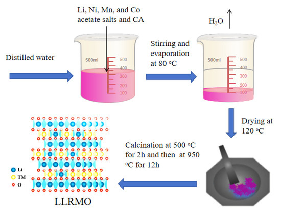
Figure 1.
Schematic diagram of synthesis progress of LRMO.
2.2. Material Characterization
The powder X-ray diffraction (XRD) and ex situ XRD measurement were conducted using a Bruker D8 Advance diffractometer equipped with a Cu-Kα radiation source in the 2θ range of 10–80°. The morphology and elemental distribution analyses of the samples were performed utilizing a scanning electron microscope (SEM, USAFEI Quanta 250 FEG, USA) and Transmission Electron Microscope (TEM, FEI Talos F200X, USA). The chemical states of the selected elements were examined by X-ray photoelectron spectrometry (XPS) on a ThermoFisher spectrometer (PHI Quantera II, ulvac-phi, Chigasaki, Japan). The contents of the chemical composition of the prepared samples were surveyed by inductively coupled plasma atomic analysis (ICP, Atomscan Advantage, TJA, USA).
2.3. Electrochemical Measurements
The cathode slurry was made of the active material, acetylene black, and polyvinylidene fluoride (PVDF, dissolved in N-methyl-2-pyrrolidone, NMP) in a mass proportion of 8:1:1. And then the slurry was coated onto aluminum foil, achieving a loading of approximately 3.0 mg cm−2. The electrodes were cut into 13 mm discs after drying under vacuum at 120 °C overnight. Battery assembly was carried out in an argon-filled glove box. The electrolyte used was 1M LiPF6 in a ratio of 1:1 ethylene carbonate/diethyl carbonate, while lithium foil was utilized as the anode. The charge and discharge profiles were obtained by galvanostatically cycling between 2.0 and 4.8 V on multi-channel battery testers (Shenzhen Neware, BTS, Shenzhen, China). Cyclic voltammetry (CV) measured at a scanning rate of 0.1 mV s−1 between 2.0 and 4.8 V (vs. Li/Li+) and electrochemical impedance spectroscopy (EIS) surveyed in a frequency range from 0.1 MHz to 0.01 Hz utilizing an amplitude of 5 mV were performed on an electrochemical workstation (CHI660C, Shanghai, China).
3. Results
3.1. Structure and Morphology
The results of the ICP are summarized in Table 1. The determined cation rations of Li:Mn:Ni:Co:La are well in accord with the intended composition, which implies that metal acetates are homogeneously reacted by the sol-gel method.

Table 1.
Chemical composition (wt.%) of the prepared samples determined by ICP.
The powder XRD analysis shown in Figure 2 reveals that all the diffraction peaks for the pristine LRMO and La-doped materials LLRMO-1, LLRMO-2, LLRMO-3, LLRMO-4, and LLRMO-5 well match a hexagonal α-NaFeO2 with the space group of R-3m. Meanwhile, the small diffraction peaks located at 20–25° correspond to the superstructure reflection of Li2MnO3 with the space group of C2/m [44,45]. Notably, the distinct peak splitting observed in the (006)/(012) and (018)/(110) reflections is a strong indicator of a well-crystallized hexagonal layered structure, which is characteristic of Li-rich layered cathode materials. Furthermore, some low-intensity peaks appear in the La-doped samples compared to LRMO, which could be attributed to the formation of the La-related impurity phase [38] and may degrade the electrochemical properties of the composite. However, the incorporation of La does not alter the main layered structure. The enlarged view of the (003) peak (Figure 2b) reveals the LLRMO peak has shifted slightly to a lower angle relative to LRMO, manifesting that the bulk doping of La3+ ions may result in the expansion of the c-axis parameter with an increasing amount of La3+. The Rietveld refinement of the XRD data was performed to obtain the quantitative crystallographic information presented in Figure 2c–h and Table 2. The lattice parameters of a, c, and the volume for LLRMO are considerably increased in comparison to the pristine material due to the larger ionic radium of La ions (La3+ = 1.15Å), which is considerably larger than that of the Li ions and TM ions. When comparing the intensity ratio of I(003)/I(104) for both the pristine LRMO and LLRMO, it is evident that the La-doped cathode exhibits a higher I(003)/I(104) ratio, signifying that well-ordered layered structures have been effectively preserved after cation doping [46]. In addition, the transfer of lithium ions can be blocked by the cation mixing through the layer during cycling, resulting in poor electrochemical performance. It can be speculated that the ordering of lithium and nickel ions could be effectively improved by La3+ doping, which is beneficial for improving the cyclability and rate capability.
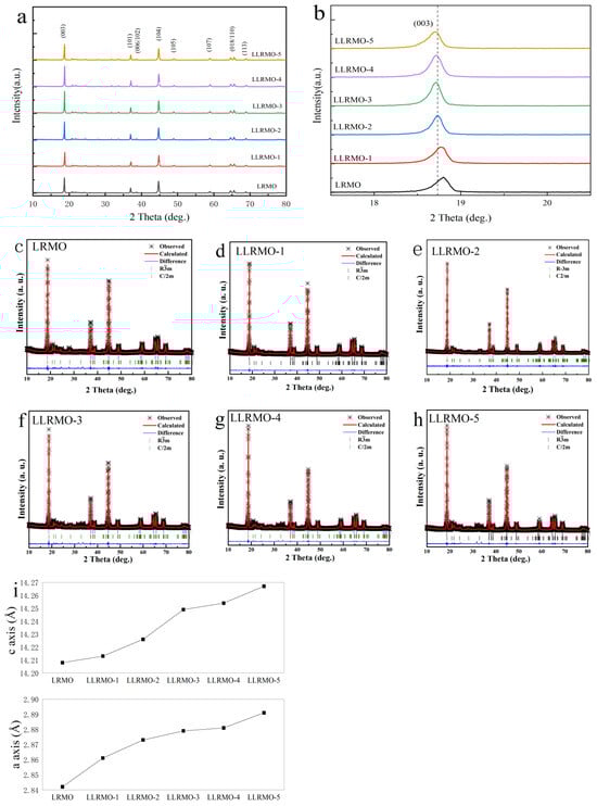
Figure 2.
XRD patterns (a,b), Rietveld refinement (c–h), and (i) lattice parameter of LRMO and La-doped LRMO materials.
Table 2.
Rietveld refinement results of XRD data for pristine and La-doped samples.
Figure 3 presents the SEM images of both the pristine LRMO and La-doped LLRMO samples. A careful examination indicates that it is challenging to discern the detailed changes in the materials before and after La doping. All the samples consist of the lamellar-like particles with a rough surface. The particle sizes are not uniform, though most of them are smaller than 1 μm. Additionally, HRTEM analysis was performed to investigate the microstructure of the materials, as illustrated in Figure 4. In Figure 4a, the interplanar spacing of 0.474 nm is clearly observed for LRMO, corresponding to the (003) plane of the R-3m phase. Conversely, for LLRMO-2, a lattice spacing of 0.474 nm can also be detected in the region marked by the curves; however, in the other areas, the lattice spacing increases to 0.475 nm (Figure 4c). Meanwhile, for LLRMO-5, the lattice spacing expands further to 0.476 nm due to increased La3+ doping (Figure 4e). These findings support that the TM spacing increases with La3+ doping, which aligns with the bulk doping results from the above XRD refinement analyses. The EDS mapping results for the pristine LRMO, LLRMO-2, and LLRMO-5 indicate a homogeneous distribution of Mn, Ni, Co, La, and O throughout the particles (Figure 4b,d,f).
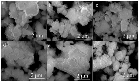
Figure 3.
SEM images of the LRMO (a), LLRMO-1 (b), LLRMO-2 (c), LLRMO-3 (d), LLRMO-4 (e), and LLRMO-5 (f).
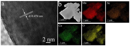
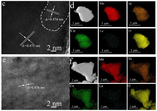
Figure 4.
HRTEM images and the corresponding EDS elemental mappings for LRMO (a,b), LLRMO-2 (c,d), and LLRMO-5 (e,f).
X-ray photoelectron spectroscopy (XPS) was employed to determine the valence states of the Mn, Ni, Co, and La elements. Figure 5 represents the typical XPS spectra for Mn 2p, Ni 2p, Co 2p, and La 3d of the LRMO and LLRMO samples. Figure 5a displays the XPS survey spectra of the pristine LRMO and LLRMO, confirming the presence of the corresponding elements in all the materials. Notably, with the increase in lanthanum doping, the XPS peaks associated with Mn, Ni, and Co exhibit a slight shift to a higher bonding energy position. Specifically, the Mn 2p3/2 peak shifts from 641.8 eV of LRMO to 642.4 eV of LLRMO-5, which is quite close to the reported value of Mn4+ in MnO2 [47] (Figure 5b). The binding energy for the Ni 2p3/2 peak changes from 854.6 eV of LRMO to 855.2 eV of LLRMO-5. Previous studies have indicated that the binding energy of Ni2+ in Li1.16Ni0.15Co0.19Mn0.50O2 is approximately at 854.0 eV [48], while that for Ni3+ in LiNiO2 is around 855.5 eV [49]. Therefore, the oxidation state of the Ni ions consists predominantly of mixed +2 and +3 states in the LRMO and La-doped samples. Furthermore, the binding energy peak of Co 2p3/2 is centered from 799.6 eV in the LRMO to 780.4 eV in LLRMO-5, which is in good agreement with the data recorded for Co3+ in LiNi1/3Co1/3Mn1/3O2 [50]. The observed shift of the binding energy position indicates changes in the chemical environment surrounding Co atoms because La is of a high affinity for oxygen and the bond energy of La-O is stronger than that of Co-O, weakening the bond of TM-O [40]. As for the La 3d spectra, the peaks of La 3d5/2 are centered at 834.6 eV and 836.3 eV, while the peaks of La 3d3/2 are located at 849.7 eV and 851.8 eV, in accordance with the La 3d peaks for La3+ [51].
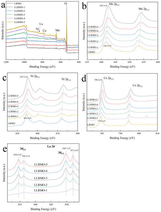
Figure 5.
XPS spectra of pristine LRMO and La-doped LLRMO samples, (a) survey lines, (b) Mn 2p, (c) Ni 2p, (d) Co 2p, and (e) La 3d.
3.2. Electrochemical Characterization
Figure 6 depicts the cyclic voltammogram (CV) curves of the pristine LRMO and LLRMO-2 samples at the scan rate of 0.1 mV s−1 in the voltage range of 2.0 and 4.8 V. In the first cycle, two anodic peaks are observed at 4.26 V and 4.77 V for the LRMO and 4.19 V and 4.76 V for the LLRMO-2 cathode. The peak around 4.2 V in both cathodes is indicative of the Ni2+/Co3+→Ni4+/Co4+ conversion, whereas the peak above 4.7 V signifies an irreversible transformation of Li2MnO3 [52,53]. The cathodic peak recorded at 3.77 V and 3.72 V in the LRMO and LLRMO-2 electrodes in their initial cycle, respectively, can be attributed to the reduction of Ni4+ and Co4+. Given the activation of the Li2MnO3 component is irreversible, the peak above 4.7 V observed in the initial charge disappears in the subsequent charge cycles; instead, a subtle peak around 3.2 V emerges, representing the reduction of Mn4+, which compensates for the charge loss resulting from irreversible oxygen loss [54]. Furthermore, potential differences between the anodic peaks and the cathodic peaks observed in both the second and third cycles related to the Ni2+/Ni4+ and Co3+/Co4+ redox couples are smaller for LLRMO-2 (0.36 V/0.25 V) compared to those seen with the pristine LRMO electrode (0.41 V/0.31 V), indicating that La doping facilitates the oxygen redox while reducing polarization [55].
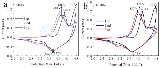
Figure 6.
Cyclic voltammetry curves of (a) LRMO and (b) LLRMO-2.
Figure 7 illustrates the cycle performance and discharge curves of LRMO and La-doped LLRMO with the current density of 100 mA g−1. As shown in Figure 7a, among all the tested electrodes, the LLRMO-2 electrode consistently demonstrates the highest discharge capacities throughout the cycling process, achieving a remarkable discharge capacity of 271.2 mAh g−1 with a capacity retention of 87.8% after 100 cycles. Although the LLRMO-1, LLRMO-3, and LLRMO-4 demonstrate similar discharge capacities to that of LLRMO-2 in the initial cycle, they gradually surpass LRMO in subsequent cycles. After 100 cycles, the LLRMO-1, LLRMO-3, and LLRMO-4 still remain at 265.3, 260.6, and 264.6 mAh g−1 with a capacity retention of 65.6%, 73.0%, and 68.2%, respectively. Conversely, the LRMO electrode remains at only 54.4% (110.6 mAh g−1) of its initial discharge capacity. For LLRMO-5, although its initial discharge capacities are significantly lower than those of the other samples, it demonstrates relatively high capacity retention at 67.3 %. The La-doped samples exhibit enhanced discharge capacities compared to the pristine LRMO, which may be due to La3+ with the large ionic diameter expanding the pathway of Li+, facilitating the diffusion of Li+. These findings also indicate that a doping amount of x = 1/100 for La3+ is optimal among the five La-doped samples, effectively enhancing both the specific capacity and cycle performance of the LRMO cathode. Additionally, as depicted in Figure 7b,c, LLRMO-2 shows markedly reduced voltage decay over extended cycling when compared to LRMO. Specifically, after 100 cycles at the current density of 100 mA g−1, the voltage degradation of LLRMO-2 is measured at just 1.60 mV per cycle, while that for LRMO is 3.70 mV and LLRMO-3 is 2.80 mV degradation. Furthermore, it also has been observed that the initial discharge curve for the LLRMO-2 cathode electrode extends significantly longer compared to the LRMO and LLRMO-3 cathode, indicating an advantageous effect of La3+ doping on reducing electrode polarization. Moreover, the electrochemical performances of the layered cathode materials doped with La3+ prepared in this work and reported in the literature were compared and the results are illustrated in Table 3. It can be found that the La-doped lithium-rich layered oxides synthesized with the sol-gel method in this work do have advantages in cyclic performance.
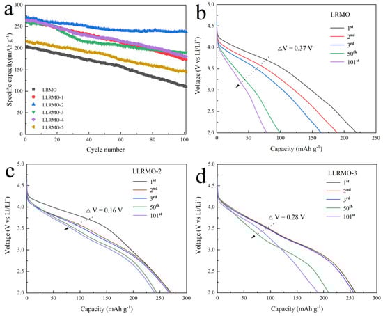
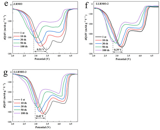
Figure 7.
Cycle performance of LRMO, LLRMO-1, LLRMO-2, LLRMO-3, LLRMO-4, and LLRMO-5 (a); discharge curves of the (b) LRMO, (c) LLRMO-2, and (d) LLRMO-3 electrodes in the 1st, 2nd, 3rd, 50th, and 101st cycles at 0.5 C between 2.0 and 4.8 V, and the corresponding dQ/dV profiles of (e) LRMO, (f) LLRMO-2, and (g) LLRMO-3 at different cycle numbers.
Table 3.
Comparison of electrochemical performances of La-doped cathode materials.
The corresponding dQ/dV profiles of the 1st, 10th, 30th, 50th, and 100th cycles are presented in Figure 7e–g to examine the structure transformation during cycling. The peak below 3.5 V is assigned to the reduction of Mn4+ to Mn3+. As the charging and discharging proceeds, the peak migrates to the lower potential, demonstrating the transition of the structure from a layered to a spinel phase [56], which is believed to be one of the major causes of voltage fading of the lithium-rich layered materials [57]. The cathodic peak of Mn4+ reduction decay is 0.51 V for LRMO, while LLRMO-2 has the smallest cathodic peak decay, at only 0.39 V among all the samples, and the decay of LLRMO-3 is 0.42 V. Apparently, in La-doped samples, the cathodic peak of Mn4+ reduction decay is depressed, and the structure stability of LLRMO-2 is greatly enhanced by an appropriate amount of La3+ doping. The good electrochemical performance of LLRMO-2 can be attributed to the alleviation the structure transformation from the layered to spinel phase and voltage fading during the cycling.
Figure 8a illustrates the rate performances of the pristine LRMO and La-doped LLRMO samples at various current densities between 2.0 and 4.8 V. With the increasing discharge current density, the discharge capacities for all the electrodes decrease, attributed to the increased polarization at a high-density current [58]. The LLRMO-1, LLRMO-2, and LLRMO-3 electrodes exhibit the significant enhanced rate capability compared with the LRMO. Though the LLRMO-4 and LLRMO-5 show a similar discharge capacity to LRMO at a low discharge current, they deliver a larger discharge capacity at high rates. As shown in Figure 8a, the LLRMO-2 cathode exhibits the best rate capabilities among all the samples. At 100 mA g−1, it shows a specific capacity of 260.8 mAh g−1. Under the high discharge rate of 800 mA g−1 and 1000 mA g−1, LLRMO-2 delivers impressive capacities of 155.3 and 138.9 mAh g−1, respectively, in contrast to the capacity of 127.8 and 103.3 mAh g−1 for the pristine material. Notably, when the current density is reverted back to 100 mA g−1 after 25 cycles, LLRMO-2 significantly achieves a higher capacity of 253.2 mAh g−1, with respect to the value of 217.8 mAh g−1 for the pristine LRMO. Such a prominent rate capability of La-doped samples is attributed to the enlargement of Li+ diffusion channels caused by the doping of La3+, facilitating the intercalation and deintercalation of Li+ [39,40]. In addition, at elevated current densities, the intercalation and deintercalation of Li ions would occur at a high speed, demonstrating stable layer structures to facilitate the movement of Li+. Therefore, it could be concluded that LLRMO-2 exhibits an improved rate capability, meaning that La3+ doping is beneficial to enhance structure stability at a high rate [59]. In addition, the lower Li/Ni mixing degree of LLRMO-2 further promotes the electrochemical reactivity, leading to better rate capabilities [40].
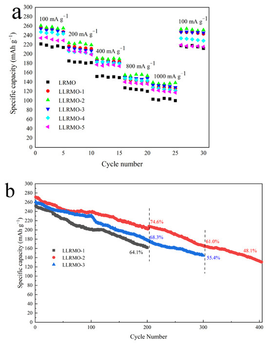
Figure 8.
Rate capabilities (a) and comparison of electrochemical performance of long cycle at the current density of 100 mA g−1 (b) of the pristine LRMO and La-doped LLRMO samples.
Figure 8b shows the electrochemical performances of different samples for long cycles at a current density of 100 mA g−1. LLRMO-2 exhibits the highest retention rate with 74.6% after 200 cycles, and the capacity decay is only 0.344 mAh g−1 per cycle. In contrast, the sample LLRMO-1 demonstrates rapid degradation, showing a capacity rate of 64.1% after 200 cycles and the capacity decay is 0.452 mAh g−1 per cycle. Furthermore, after 300 cycles, the LLRMO-2 sample maintains a specific capacity of 165.4 mAh g−1 with a retention rate of 61.0%, while LLRMO-3 delivers a specific capacity of 144.4 mAh g−1 with a retention rate of 55.4%. These results indicate that LLRMO-2 experiences less voltage polarization compared to LRMO and LLRMO-3, implying an enhancement in structural stability after modification by doping La with 1/100. This improvement can be attributed to the facilitated Li+ diffusion and the enlargement of the (003) interlayer resulting from the doping.
To gain a deeper understanding of the improved electrochemical performance of the La-doped sample, an EIS analysis was performed and the corresponding results about impedance are shown as the Nyquist plots in Figure 9a. The insert in Figure 9a depicts the equivalent circuits designed to correlate with the experimental data obtained. The onset of the semicircles indicates the solution resistance (Rs) of the lithium-ion battery system. These semicircles are associated with the charge transfer resistance (Rct). CPE refers to a constant phase element while Wo is associated with the semi-infinite Warburg diffusion impedance in the bulk. The simulated values of Rs and Rct are summarized in Table 4. It is evident that La-doped samples exhibit significantly lower charge transfer resistances compared to the pristine sample, thereby confirming the remarkable modification effect of La3+ doping to the LRMO sample. Additionally, the diffusion coefficient of Li+ can also be determined from the Warburg impedance derived from EIS, as outlined in Equation (1):
where R represents the gas constant (8.314 J K−1 mol−1); T denotes the Kelvin temperature (298 K); and n, A, F, and C refer to the number of electrons transferred during the reaction, the electrode area, the Faraday constant (96,500 C mol−1), and the lithium-ion bulk concentration, respectively. The variable stands for the slope of inclined line fitting Z’ vs. ω−1/2 (Figure 9b) [60]. The average DLi+ values of the pristine sample and La-doped samples are listed in Table 4. Notably, LLRMO-2 exhibits a DLi+ value that is over 23 times greater than that of LRMO and maintains a high DLi+ in all the samples. Due to the the higher Li+ diffusion coefficient and lower electrochemical impedance of LLRMO-2, its cyclic performance and rate capability surpass those of the other samples. This finding indicated that La doping contributes to the increase in the Li+ diffusion coefficient of the Li-rich Mn-based layered cathode materials to a certain extent; however, this enhancement does not consistently correlate with the amount of doping. With the increase in La3+, the DLi+ of samples LLRMO-3, LLRMO-4, and LLRMO-5 becomes smaller and the DLi+ of LLRMO-5 is smallest but larger than the pristine sample LRMO. Many factors such as the Li/Ni mixing degree, the c/a ratio, the doping amount, and the structural stability of the cathode can influence the Li+ diffusion coefficient of these materials. However, too much La3+ leads to the generation of impurities, which blocks the Li+ diffusion channel and is unfavorable to the migration of Li+. This result is in good accordance with the variation trend of the cyclic performances and rate capability, essentially illustrating the performance improvement in the LLRMO-2 cathode materials.
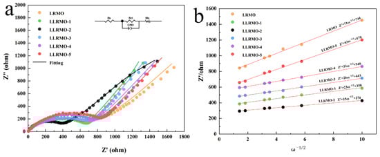
Figure 9.
(a) Nyquist surveys of as-synthesized materials; (b) plots of Z′ vs. w−1/2 in the low-frequency region of the LRMO, LLRMO-1, LLRMO-2, LLRMO-3, LLRMO-4, and LLRMO-5 in open-circuit conditions.
Table 4.
Simulated data from the EIS spectra of the LRMO, LLRMO-1, LLRMO-2, LLRMO-3, LLRMO-4, and LLRMO-5.
To further elucidate structural evolution during the initial charging and discharging processes, the ex situ XRD profiles at 100 mA g−1 within a voltage range of 2.0–4.8 V are presented in Figure 10. As illustrated in Figure 10a,b, for both the LRMO and LLRMO-2 cathodes, the evolution of the peaks is quite similar. The (003) peak gradually shifts to lower angles during the charging process, which corresponds to an increased interlayer distance along the c-axis due to the enhanced electrostatic repulsion between the O layers as the continuous extraction of Li+ and the activation of Li2MnO3 upon the extraction of Li+ from the TM layer [20]. Conversely, the (104) peak shifts to a higher angle, consistent with a contracted interlayer distance along the a-axis resulting from the reduced ionic radius of the TM ions after oxidation. Notably, both the (003) and (104) peaks in LLRMO-2 demonstrate smaller shifts compared to those observed in LRMO, indicating that La doping can stabilize the crystal structure. In addition, during discharging, the (003) peaks show an obvious reverse shift, and the location of the (003) peak for LRMO deviates from its location prior to charging, suggesting that LRMO has suffered irreversible structural degradation, while the structure of LLRMO-2 can be well maintained [13,61,62]. This can be quantitatively evidenced by the changes in lattice parameters a and c during charging and discharging, as shown in Figure 10c,d. A relatively smaller change in both a and c could be observed for LLRMO-2 during charge and discharge, implying less severe lattice distortion and strains. In contrast, LRMO exhibits a significantly greater variation in these parameters. Notably, during the initial charge processes, LRMO demonstrates a substantial volume change of 1.3480 Å3, whereas LLRMO-2 achieves a smaller ΔV of 0.8405 Å3, which indicates that La doping effectively alleviates lattice strain and reduces the irreversible distortion of the MnO6 octahedron during the charging process at high voltage, ultimately leading to excellent electrochemical properties. Furthermore, after the initial cycle, LLRMO-2 shows less expansion of the unit cell volume compared to the LRMO material. The improvement mechanism of the La-doping strategy on the Li deintercalation/intercalation was elucidated by the above study, which primarily attributed to the suppression of lattice strain. These effects play a significant role in mitigating structural deterioration post-cycling.
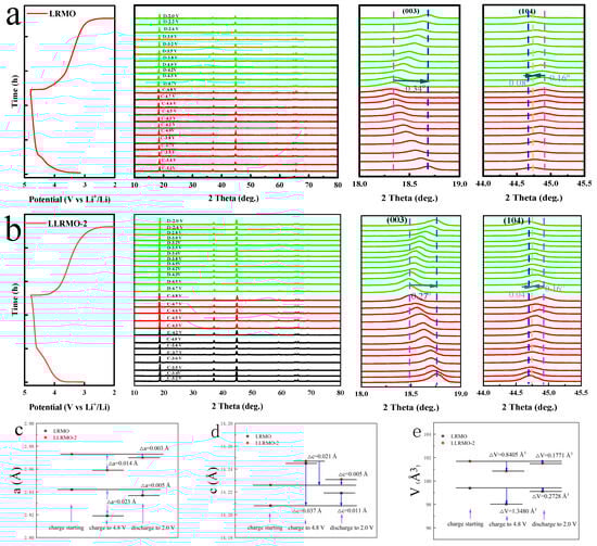
Figure 10.
Ex situ XRD patterns of the LRMO (a) and LLRMO-2 (b). The change in lattice parameters a, b, and volume V (c–e) in the initial charge and discharge process for LRMO and LLRMO-2.
4. Conclusions
The doping of the La3+ ions in the Li-rich Mn-based cathode materials was achieved by a simple sol-gel method, significantly enhancing cyclic stability. Various characterization techniques, including XRD, XPS, TEM, and electrochemical measurements, were employed to investigate the structure, morphology, and electrochemical properties of the materials. The Rietveld refinement results of the parameters of the La-doped samples are larger than those of the pristine sample. And the increased interatomic layer spacing facilitates lithium-ion diffusion, thereby improving the rate capability and cyclic stability. Notably, the capacity retention improved from 54.4% to 87.8% at the current density of 100 mA g−1 after 100 cycles for the pristine and doped La with 1/100 samples. Specially, the LLRMO-2 shows 48.1% capacity retention after 400 cycles. With the increase in the current density, the doping effect gets more noticeable. At the high discharge rate of 800 mA g−1 and 1000 mA g−1, LLRMO-2 delivers impressive capacities of 155.3 and 138.9 mAh g−1, respectively, in contrast to the capacity of 127.8 and 103.3 mAh g−1 for the pristine material. Furthermore, compared to the pristine material, the La-doped cathode material exhibits reduced crystal lattice change during the charge–discharge process and enhanced the structural stability. Simultaneously, the La-doped samples exhibit significantly lower charge transfer resistances and a higher Li+ diffusion coefficient compared to the pristine sample. Therefore, the sol-gel strategy for La doping is crucial for designing next-generation high-performance lithium-rich Mn-based layered cathode materials.
Author Contributions
S.D. proposed the concept of this work. B.L., R.T. and Z.G. conducted the experiments and data analysis. W.Z. and L.R. carried out the measurements. F.W. supervised the research. S.D., B.L. and H.L. wrote this manuscript. All the authors discussed the results and commented on this manuscript. All authors have read and agreed to the published version of the manuscript.
Funding
This work was financially supported by the National Natural Science Foundation of China (52472083), the Natural Science Foundation Research Project of Shaanxi Province (2023-JC-YB-120), the Scientific Research Foundation for Talented Scholars of Baoji University of Arts and Sciences (203408), and the National Undergraduate Training Programs for Innovation and Entrepreneurship (202410721008).
Institutional Review Board Statement
Not applicable.
Informed Consent Statement
Not applicable.
Data Availability Statement
The original contributions presented in this study are included in the article. Further inquiries can be directed to the corresponding author.
Conflicts of Interest
The authors declare no conflicts of interest.
References
- Goodenough, J.B.; Gao, H. A perspective on the Li-ion battery. Sci. China Chem. 2019, 62, 1555–1556. [Google Scholar] [CrossRef]
- Li, M.; Lu, J.; Chen, Z.; Amine, K. 30 Years of Lithium-Ion Batteries. Adv. Mater. 2018, 30, 1800561. [Google Scholar] [CrossRef] [PubMed]
- Manthiram, A. An Outlook on Lithium Ion Battery Technology. ACS Cent. Sci. 2017, 10, 1063–1069. [Google Scholar] [CrossRef]
- Xie, J.; Lu, Y. A retrospective on lithium-ion batteries. Nat. Commun. 2020, 11, 2499. [Google Scholar] [CrossRef]
- Cheng, Q.; He, W.; Zhang, X.; Li, M.; Wang, L. Modification of Li2MnSiO4 cathode materials for lithium-ion battery: A review. J. Mater. Chem. A 2017, 7, 10772. [Google Scholar] [CrossRef]
- Wang, F.; Wu, X.; Li, C.; Fu, L.; Liu, X. Nanostructured positive electrode materials for post-lithium ion batteries. Energy Environ. Sci. 2016, 6, 3570–3611. [Google Scholar] [CrossRef]
- Toprakci, O.; Toprakci, H.; Li, Y.; Jim, L.; Xue, L.; Lee, H.; Zhang, S.; Zhang, X. Synthesis and characterization of xLi2MnO3·(1−x)LiMn1/3Ni1/3Co1/3O2 composite cathode materials for rechargeable lithium-ion batteries. J. Power Sources 2013, 241, 522–528. [Google Scholar] [CrossRef]
- Liu, J.; Chen, L.; Hou, M.; Wang, F.; Che, R.; Xia, Y. General synthesis of xLi2MnO3·(1-x)LiMn1/3Ni1/3Co1/3O2 nanomaterials by a molten-salt method: Towards a high capacity and high power cathode for rechargeable lithium batteries. J. Mater. Chem. 2012, 22, 25380–25387. [Google Scholar] [CrossRef]
- Thackeray, M.; Johnson, C.; Vaughey, J.; Li, N.; Hackney, S. Advances in manganese-oxide composite electrodes for lithium-ion batteries. J. Mater. Chem. 2019, 15, 2257–2267. [Google Scholar] [CrossRef]
- Wu, F.; Maier, J.; Yu, Y. Guidelines and trends for next-generation rechargeable lithium and lithium-ion batteries. Chem. Soc. Rev. 2020, 49, 1569–1614. [Google Scholar] [CrossRef]
- Zheng, F.; Yang, C.; Xiong, X.; Xiong, J.; Hu, R.; Chen, Y.; Liu, M. Nanoscale surface modification of lithium-rich layered-oxide composite cathodes for suppressing voltage fade. Angew. Chem. Int. Ed. Engl. 2019, 54, 13058–13062. [Google Scholar] [CrossRef] [PubMed]
- Fu, F.; Wang, Q.; Deng, Y.; Shen, C.; Peng, X.; Huang, L.; Sun, S. Effect of synthetic routes on the rate performance of Li-rich layered Li1.2Mn0.56Ni0.12Co0.12O2. J. Mater. Chem. A 2015, 3, 5197–5203. [Google Scholar] [CrossRef]
- Guo, J.; Lai, Y.; Gao, X.; Li, S.; Zhang, H.; Guan, C.; Chen, L.; Yang, Z.; Li, S.; Zhang, Z. Triggering cationic/anionic hybrid redox stabilizes high-temperature Li-rich cathodes materials via three-in-one strategy. Energy Storage Mater. 2024, 69, 103383. [Google Scholar] [CrossRef]
- Liu, Q.; Xie, T.; Xie, Q.; He, W.; Zhang, Y.; Zheng, H.; Lu, X.; Wei, W.; Sa, B.; Wang, L.; et al. Multiscale deficiency integration by Na-rich engineering for high stability Li-rich layered oxide cathodes. ACS Appl. Mater. Interfaces 2021, 13, 8239–8248. [Google Scholar] [CrossRef]
- Wang, E.; Xiao, D.; Wu, T.; Liu, X.; Zhou, Y.; Wang, B.; Lin, T.; Zhang, X.; Yu, H. Al/Ti synergistic doping enhanced cycle stability of Li-rich layered oxides. Adv. Funct. Mater. 2022, 32, 2201744. [Google Scholar] [CrossRef]
- Guo, L.; Tan, X.; Mao, D.; Zhao, T.; Song, L.; Liu, Y.; Kang, X.; Wang, H.; Sun, L.; Chu, W. Improved electrochemical activity of the Li2MnO3-like superstructure in high-nickel Li-rich layered oxide Li1.2Ni0.4Mn0.4O2 and its enhanced performances via tungsten doping. Electrochim. Acta 2021, 370, 137808. [Google Scholar] [CrossRef]
- Zhang, K.; Sheng, H.; Wu, X.; Fu, L.; Liu, Z.; Zhou, C.; Holze, R.; Wu, Y. Improving electrochemical properties by sodium doping for lithium-rich layered oxides. ACS Appl. Energy Mater. 2020, 3, 8953–8959. [Google Scholar] [CrossRef]
- Wang, E.; Xiao, D.; Wu, T.; Wang, B.; Wang, Y.; Wu, L.; Zhang, X.; Yu, H. Stabilizing Oxygen by High Valance Element Doping for High-Performance Li-Rich Layered Oxides. Battery Energy 2023, 2, 20220030. [Google Scholar] [CrossRef]
- He, W.; Liu, P.; Qu, B.; Zheng, Z.; Zheng, H.; Pan, D.; Li, P.; Li, S.; Huang, H.; Wang, L.; et al. Uniform Na+ Doping-Induced Defects in Li- and Mn-Rich Cathodes for High-Performance Lithium-Ion Batteries. Adv. Sci. 2019, 6, 1802114. [Google Scholar] [CrossRef]
- Wang, G.; Xie, C.; Wang, H.; Li, Q.; Xia, F.; Zeng, W.; Peng, H.; Tendeloo, G.; Tan, G.J.; Tian, J.; et al. Mitigated Oxygen Loss in Lithium-Rich Manganese-Based Cathode Enabled by Strong Zr-O Affinity. Adv. Funct. Mater. 2024, 34, 2313672. [Google Scholar] [CrossRef]
- Peng, P.; Chen, Y.; Zhou, Q.; Shen, L.; Wen, Y.; Du, F.; Chen, Y.; Zheng, J. Structure engineering with sodium doping for cobalt-free Li-rich layered oxide toward improving electrochemical stability. J. Colloid. Interf. Sci. 2024, 676, 847–858. [Google Scholar] [CrossRef] [PubMed]
- Zhang, C.; Wei, B.; Wang, M.; Zhang, D.; Uchiyama, T.; Liang, C.; Chen, L.; Uchimoto, Y.; Zhang, R.; Wang, P.; et al. Regulating oxygen covalent electron localization to enhance anionic redox reversibility of lithium-rich layered oxide cathodes. Energy Storage Mater. 2022, 46, 512–522. [Google Scholar] [CrossRef]
- Hu, S.; Li, Y.; Chen, Y.; Peng, J.; Zhou, T.; Pang, W.; Didier, C.; Peterson, V.; Wang, H.; Li, Q.; et al. Insight of a Phase Compatible Surface Coating for Long-Durable Li-Rich Layered Oxide Cathode. Adv. Energy Mater. 2019, 9, 1901795. [Google Scholar] [CrossRef]
- Hall, D.; Gauthier, R.; Eldesoky, A.; Murray, V.; Dahn, J. New Chemical Insights Into the Beneficial Role of Al2O3 Cathode Coatings in Lithium-Ion Cells. ACS Appl. Mater. Interfaces 2019, 11, 14095–14100. [Google Scholar] [CrossRef]
- Ran, X.; Tao, J.; Chen, Z.; Yan, Z.; Yang, Y.; Li, J.X.; Lin, Y.; Huang, Z. Surface heterostructure induced by TiO2 modification in Li-rich cathode materials for enhanced electrochemical performance. Electrochim. Acta 2020, 353, 135959. [Google Scholar] [CrossRef]
- Jiao, C.; Wang, M.; Huang, B.; Zhang, M.; Xu, G.; Liu, Y.; Zhao, Y.; Hu, X. Surface modification single crystal Li-rich Li1.2Mn0.54Ni0.13Co0.13O2 as high performance cathode materials for Li-ion batteries. J. Alloy Compd. 2023, 937, 168389. [Google Scholar] [CrossRef]
- Zhuang, Y.; Du, F.; Zhu, L.; Cao, H.; Dai, H.; Adkins, J.; Zhou, Q.; Zheng, J. Trimethylsilyl (trimethylsiloxy) acetate as a novel electrolyte additive for improvement of electrochemical performance of lithium-rich Li1.2Ni0.2Mn0.6O2 cathode in lithium-ion batteries. Electrochim. Acta 2018, 290, 220–227. [Google Scholar] [CrossRef]
- Song, J.; Li, B.; Chen, Y.; Zuo, Y.; Ning, F.; Shang, H.; Feng, G.; Liu, N.; Shen, C.; Ai, X.; et al. A High-Performance Li-Mn-O Li-Rich Cathode Material with Rhombohedral Symmetry via Intralayer Li/Mn Disordering. Adv. Mater. 2020, 32, 2000190. [Google Scholar] [CrossRef]
- Jiang, Y.; Yu, F.; Que, L.; Deng, L.; Xia, Y.; Ke, W.; Han, Y.; Wang, Z. Revealing the Thermodynamics and Kinetics of in-Plane Disordered Li2MnO3 Structure in Li-Rich Cathodes. ACS Energy Lett. 2021, 6, 3836–3843. [Google Scholar] [CrossRef]
- Ning, F.; Li, B.; Song, J.; Zuo, Y.; Shang, H.; Zhao, Z.; Yu, Z.; Chu, W.; Zhang, K.; Feng, G.; et al. Inhibition of Oxygen Dimerization by Local Symmetry Tuning in Li-Rich Layered Oxides for Improved Stability. Nat. Commun. 2020, 11, 4973. [Google Scholar] [CrossRef]
- Jiang, Y.; Liao, Z.; Yu, F.; Ke, W.; Li, X.; Xia, Y.; Xu, G.; Sun, G.; Xia, Y.; Yin, W.; et al. A Cable-Stayed Honeycomb Superstructure to Improve the Stability of Li-Rich Materials via Inhibiting Interlaminar Lattice Strain. Adv. Mater. 2024, 36, 2404982. [Google Scholar] [CrossRef] [PubMed]
- Zhang, B.; Zhang, Y.; Wang, X.; Liu, H.; Yan, Y.; Zhou, S.; Tang, Y.; Zeng, G.; Wu, X.; Liao, H.; et al. Role of Substitution Elements in Enhancing the Structural Stability of Li-Rich Layered Cathodes. J. Am. Chem. Soc. 2023, 145, 8700–8713. [Google Scholar] [CrossRef] [PubMed]
- Dou, S.; Tan, D.; Li, P.; Li, H.; Wei, F.; Zhang, H. Research progress and prospect in element doping of lithium-rich layered oxides as cathode materials for lithium-ion batteries. J. Solid State Electr. 2023, 27, 1–23. [Google Scholar] [CrossRef]
- Yu, R.; Zhang, Z.; Jamil, S.; Chen, J.; Zhang, X.; Wang, X.; Yang, Z.; Shu, H.; Yang, X. Effects of nanofiber architecture and antimony doping on the performance of lithium-rich layered oxides: Enhancing lithium diffusivity and lattice oxygen stability. ACS Appl. Mater. Interfaces 2018, 10, 16561–16571. [Google Scholar] [CrossRef]
- Wang, C.; Lin, Y.; Chiu, K. Alleviation of voltage fade of lithium-rich layered oxide cathodes of Li-ion battery by incorporation of Cr. J. Alloys Compd. 2017, 721, 600–608. [Google Scholar] [CrossRef]
- Kang, S.; Qin, H.; Fang, Y.; Li, X.; Wang, Y. Preparation and electrochemical performance of yttrium-doped Li[Li0.20Mn0.534Ni0.133Co0.133]O2 as cathode material for lithium-ion batteries. Electrochim. Acta 2014, 144, 22–30. [Google Scholar] [CrossRef]
- Xie, Z.; Wu, X.; Zhang, Y.; Li, G.; Ma, F.; Yan, W.; Chen, Y.; Li, F.; Zhou, M. Insight into the effect of Nb5+ on the crystal structure and electrochemical performance of the Li-rich cathode materials. J. Electroanal. Chem. 2022, 922, 116762. [Google Scholar] [CrossRef]
- Yu, R.; Wang, G.; Liu, M.; Zhang, X.; Wang, X.; Shu, H.; Yang, X.; Huang, W. Mitigating voltage and capacity fading of lithium-rich layered cathodes by lanthanum doping. J. Power Sources 2016, 335, 65–75. [Google Scholar] [CrossRef]
- Li, M.; Wang, H.; Zhao, L.; Zhou, F.; Zhang, F.; He, D. Improving the electrochemical performance of lithium-rich oxide layer material with Mg and La cooping. J. Alloy Compd. 2019, 782, 451–460. [Google Scholar] [CrossRef]
- Wang, M.; Chen, L.; Liu, M.; Chen, Y.; Gu, Y. Enhanced electrochemical performance of La-doped Li-rich layered cathode material. J. Alloy Compd. 2020, 848, 156620. [Google Scholar] [CrossRef]
- Lu, C.-H.; Li, W.; Subburaj, T.; Ou, C.; Kumar, P.S. Influence of bio-derived agar addition on the electrochemical performance of LiFePO4 cathode powders for Li-ion batteries. Ceram. Int. 2019, 45, 12218–12224. [Google Scholar] [CrossRef]
- Dong, P.; Xia, S.; Zhang, Y.-J.; Zhang, Y.; Qiu, Z.; Yao, Y. Influence of Complexing Agents on the Structure and Electrochemical Properties of LiNi0.80Co0.15Al0.05O2 Cathode Synthesized by Sol-Gel Method: A Comparative Study. Int. J. Electrochem. Sci. 2017, 12, 561–575. [Google Scholar]
- Chen, C.; Wu, H.; Zhou, D.; Xu, D.; Zhou, Y.; Guo, J. Sol-gel synthesis of nano Li1.2Mn0.54Ni0.13Co0.13O2 cathode materials using DL-lactic acid as chelating agent. Ceram. Int. 2021, 47, 6270–6278. [Google Scholar] [CrossRef]
- Jiang, W.; Zhang, C.; Feng, Y.; Wei, B.; Chen, L.; Zhang, R.; Ivey, D.; Wang, P.; Wei, W. Achieving high structure and voltage stability in cobalt-free Li-rich layered oxide cathodes via selective dual-cation doping. Energy Storage Mater. 2020, 32, 37–45. [Google Scholar] [CrossRef]
- Wang, J.; Qiu, B.; Cao, H.; Xia, Y.; Liu, Z. Electrochemical properties of 0.6Li[Li1/3Mn2/3]O2-0.4LiNixMnyCo1-x-yO2 cathode materials for lithium-ion batteries. J. Power Sources 2012, 218, 128–133. [Google Scholar] [CrossRef]
- Zheng, J.; Ye, Y.; Liu, T.; Xiao, Y.; Wang, C.; Wang, F.; Pan, F. Ni/Li Disordering in Layered Transition Metal Oxide: Electrochemical Impact, Origin, and Control. Acc. Chem. Res. 2019, 52, 2201–2209. [Google Scholar] [CrossRef]
- Mao, G.; Yang, Y.; Yao, Y.; Jiao, W.; Yao, Y.; Yu, W.; Tong, H.; He, H. Boron and Magnesium Ions Co-doping Synergistically Enhances the Electrochemical Performance of Nickel-rich Cathode Materials. J. Electroanal. Chem. 2023, 946, 17730. [Google Scholar] [CrossRef]
- Oishi, M.; Fujimoto, T.; Takanashi, Y.; Orikasa, Y.; Kawamura, A.; Ina, T.; Yamashige, H.; Takamatsu, D.; Sato, K.; Murayama, H.; et al. Charge compensation mechanisms in Li1.16Ni0.15Co0.19Mn0.50O2 positive electrode material for Li-ion batteries analyzed by a combination of hard and soft X-ray absorption near edge structure. J. Power Sources 2023, 222, 45–51. [Google Scholar] [CrossRef]
- Wang, Y.; Bie, X.; Nikolowski, K.; Ehrenberg, H.; Du, F.; Hinterstein, M.; Wang, C.; Chen, G.; Wei, Y. Relationships between Structural Changes and Electrochemical Kinetics of Li-Excess Li1.13Ni0.3Mn0.57O2 during the First Charge. J. Phys. Chem. C 2013, 117, 3279–3286. [Google Scholar] [CrossRef]
- Sun, Y.; Shiosaki, Y.; Xia, Y.; Noguchi, H. The preparation and electrochemical performance of solid solutions LiCoO2-Li2MnO3 as cathode materials for lithium ion batteries. J. Power Sources 2006, 159, 1353–1359. [Google Scholar] [CrossRef]
- Tang, Q.; Liu, C.; Lv, D.; Zhao, L.; Jiang, L.; Wang, J. Biotemplated Fe/La-co-doped TiO2 for photocatalytic depth treatment of compressed leachate from refuse transfer station. Environ. Sci. Pollut. R. 2024, 31, 40941–40957. [Google Scholar] [CrossRef] [PubMed]
- Liu, J.; Liu, Q.; Zhu, H.; Lin, F.; Ji, Y.; Li, B.; Duan, J.; Li, L.; Chen, Z. Effect of different composition on voltage attenuation of Li-rich cathode material for Lithium-ion batteries. Materials 2021, 13, 40. [Google Scholar] [CrossRef] [PubMed]
- Liu, Z.; Zhang, Z.; Liu, Y.; Li, L.; Fu, S. Facile and scalable fabrication of K+-doped Li1.2Ni0.2Co0.08Mn0.52O2 cathode with ultra high capacity and enhanced cycling stability for lithium ion batteries. Solid State Ion. 2019, 332, 47–54. [Google Scholar] [CrossRef]
- Etefagh, R.; Rozati, S.; Mohammad, D.; Ahmad, A.; Poursalehi, F.; Keshmarzi, M.K. Enhanced Li-storage performance of In-doped Li1.21[Mn0.54Ni0.125Co0.125]O2 as Li-and Mn-rich cathode materials for lithium-ion batteries. J. Appl. Electrochem. 2022, 52, 461–475. [Google Scholar] [CrossRef]
- Wang, H.; Liu, F.; Yu, R.; Xiao, Z.; Zhu, Z.; Zhou, L.; Wu, J. Co-gradient Li-rich cathode relieving the capacity decay in Lithium-ion batteries. Nano Energy 2022, 100, 107439. [Google Scholar] [CrossRef]
- Zhou, Z.; Luo, Z.; He, Z.; Zheng, J.; Li, Y.; Yan, C.; Mao, J. Suppress voltage decay of lithium-rich materials by coating layers with different crystalline states. J. Energy Chem. 2021, 60, 591–598. [Google Scholar] [CrossRef]
- Yang, F.; Liu, Y.; Martha, S.K.; Wu, Z.; Andrews, J.C.; Ice, G.E.; Pianetta, P.; Nanda, J. Nanoscale morphological and chemical changes of high voltage lithium-manganese rich NMC composite cathodes with cycling. Nano Lett. 2014, 14, 4334–4341. [Google Scholar] [CrossRef]
- Chen, M.; Chen, D.; Liao, Y.; Zhong, X.; Li, W.; Zhang, Y. Layered lithium-rich oxide nanoparticles doped with spinel phase: Acidic sucrose-assistant synthesis and excellent performance as cathode of lithium ion battery. ACS Appl. Mater. Interfaces 2016, 8, 4575–4584. [Google Scholar] [CrossRef]
- Fu, C.; Meng, L.; Wang, J.; Wang, Q.; Yang, K.; Zhang, W.; Li, L. Bonding the Terminal Isocyanate-Related Functional Group to the Surface Manganese Ions to Enhance Li-Rich Cathode’s Cycling Stability. ACS Appl. Mater. Interfaces 2021, 13, 17565–17576. [Google Scholar] [CrossRef]
- Lu, G.; Peng, W.; Zhang, Y.; Wang, X.; Shi, X.; Song, D.; Zhang, H.; Zhang, L. Study on the formation, development and coating mechanism of new phases on interface in LiNbO3-coated LiCoO2. Electrochim. Acta 2021, 368, 137639. [Google Scholar] [CrossRef]
- Zhang, X.; Shi, J.; Liang, J.; Yin, Y.; Zhang, J.; Yu, X.; Guo, Y. Suppressing Surface Lattice Oxygen Release of Li-Rich Cathode Materials via Heterostructured Spinel Li4Mn5O12 Coating. Adv. Mater. 2018, 30, 1801751. [Google Scholar] [CrossRef]
- Ni, L.; Chen, H.; Gao, J.; Mei, Y.; Wang, H.; Deng, W.; Zou, G.; Hou, H.; Ji, X. Multiscale Crystal Field Effect for High-Performance Ultrahigh-Ni Layered Cathode. ACS Nano 2023, 17, 12759–12773. [Google Scholar] [CrossRef]
Disclaimer/Publisher’s Note: The statements, opinions and data contained in all publications are solely those of the individual author(s) and contributor(s) and not of MDPI and/or the editor(s). MDPI and/or the editor(s) disclaim responsibility for any injury to people or property resulting from any ideas, methods, instructions or products referred to in the content. |
© 2025 by the authors. Licensee MDPI, Basel, Switzerland. This article is an open access article distributed under the terms and conditions of the Creative Commons Attribution (CC BY) license (https://creativecommons.org/licenses/by/4.0/).