Article

Study on the Energy Storage and Driving Performance of IPMC with Laminated Structure Electrodes

1
School of Mechanical and Power Engineering, Harbin University of Science and Technology, 52 Xuefu Road, Harbin 150080, China
2
Rongcheng Campus, Harbin University of Science and Technology, 2006 College Road, Weihai 264200, China
*
Author to whom correspondence should be addressed.
Coatings 2025, 15(5), 577; https://doi.org/10.3390/coatings15050577
Submission received: 17 April 2025 / Revised: 1 May 2025 / Accepted: 7 May 2025 / Published: 13 May 2025
(This article belongs to the Special Issue Cutting Performance of Coated Tools)

Abstract

:
Ionic polymer–metal composites (IPMC) have the advantages of a large driving mass ratio, low driving voltage, and high current sensitivity, but their low electrode continuity, low energy storage, and unclear driving response mechanisms limit further application and development. In this study, Nafion is used as the base film and metallic silver is used as the electrode material to modify IPMC electrodes. The physical and electrochemical properties of silver-based IPMC with three electrode preparation processes are tested, and the effects of different electrode preparation processes and structures on the energy storage performance and driving performance of IPMC are analyzed. The results show that the electrode coating effect of the Hot Press Chemical Plating method (HPCP) is good and maintains better continuity, and the formed layer electrode can improve the energy storage performance of IPMC, and the enhancement of energy storage performance can improve the driving performance of IPMC. This study enhances the energy storage performance and driving performance of IPMC from the perspective of electrode process and structure and provides a basis for the study of the enhancement of energy storage performance of IPMC by the HPCP electrode preparation process.

Graphical Abstract

1. Introduction

Ionic polymer–metal composites (IPMC) have emerged as a highly promising class of smart materials due to their unique performance advantages, such as low energy consumption [1,2], low driving voltage [3], lightweight properties [4], and excellent hydrophilicity [5,6,7]. These characteristics make them particularly attractive for applications in biomimetic robotics [8], sensors, and biomedical devices [9]. However, despite these notable advantages, challenges such as electrode discontinuity, low energy storage capacity, and unclear actuation mechanisms significantly hinder their industrial-scale application.
The performance of IPMC is highly dependent on electrode fabrication processes. Although traditional methods like Chemical Plating (CP) and Hot Pressing (HP) have been extensively studied, they exhibit evident limitations. For instance, electrodes prepared by chemical plating often suffer from poor continuity and uneven deposition, leading to crack formation and reduced conductivity [10]. In contrast, hot-pressed electrodes demonstrate superior in-plane conductivity but are prone to vertical discontinuity, while high temperature and pressure can cause membrane deformation [11]. As Wang [12] explicitly demonstrated, electrode quality directly impacts the actuation efficiency of IPMC.
Recent studies have explored various electrode materials and structures to address these issues. Sadat [13] confirmed that nanocomposite electrodes could enhance IPMC performance by improving interfacial adhesion and conductivity, while Hasani [14] found that sputtered electrodes outperformed traditional methods in terms of durability and performance. However, these approaches often face limitations due to complex processes or high costs [15].
The continuity of the electrode layer in both horizontal and vertical directions is critical for IPMC performance. Zhang [16] emphasized that discontinuous electrodes result in uneven electric fields, reducing actuation efficiency. Furthermore, the energy storage capacity of IPMC, typically measured by specific capacitance, plays a decisive role in their actuation performance. Studies by Hall [17] revealed that hierarchical electrode structures could significantly improve capacitive performance by facilitating charge transfer. This corroborates the discovery that porous layered electrodes improve both energy storage and mechanical output.
As research progresses, it has been established that both electrode quality and ion-exchange membrane properties influence the actuation performance of IPMC [18,19]. However, systematic investigations into how electrode fabrication processes and structures affect energy storage and actuation performance remain insufficient. The actuation performance of IPMC exhibits nonlinear variations with improvements in electrode energy storage capacity, while the adhesion between the electrode layer and the exchange membrane layer also impacts energy storage performance [20,21]. In particular, the synergistic effects of combining chemical plating and hot pressing to prepare layered electrodes have not been thoroughly explored. This study innovatively proposes a hybrid HPCP process. By comparatively analyzing the physical characteristics, electrochemical properties, and mechanical performance of HPCP samples against traditional CP and HP samples, we elucidate the correlation mechanism among electrode structure, energy storage performance, and actuation efficiency. The findings will provide a theoretical foundation for developing high-performance IPMC actuators, advancing their practical applications in soft robotics, biomedical devices, and related fields.

2. Materials and Methods

The experiments use a Nafion 117 homemade membrane (State of Delaware, USA) as the ion exchange membrane, metallic silver as the electrode material, and three electrode preparation processes (CP, HP, and HPCP) to prepare IPMC with different electrode structures, in which the CP electrode is horizontally discontinuous, the HP electrode is vertically discontinuous, and the HPCP electrode is laminated. The physical properties and energy storage performance of the three types of IPMC were tested to investigate the influence of the electrode preparation process on the electrical conductivity and driving performance of IPMC.
The Nafion 117 membrane underwent a three-step chemical pretreatment process. Initially, the membrane was immersed in 3% (w/v) H2O2 solution at 80 °C for 1 h to eliminate organic impurities. Subsequently, it was transferred to 1 M H2SO4 solution and maintained at 80 °C for 1 h to achieve complete protonation of sulfonic acid groups. Finally, the membrane was subjected to three cycles of ultrasonic cleaning in deionized water at 60 °C (30 min per cycle), followed by drying in a vacuum oven at 80 °C for 2 h until constant weight was attained. The IPMC silver electrodes were fabricated using three different processes: (1) Hot pressing (HP): the pretreated Nafion 117 membrane was uniformly coated with Nafion D520 solution (State of Delaware, USA) as an adhesive layer on both sides, covered with silver foil, and then placed in a hot press at 80 °C under 1000 N pressure for 80 min, followed by pressure-maintained cooling to room temperature. (2) Chemical plating (CP): the Nafion membrane, after surface roughening with 2000-grit sandpaper, was ultrasonically cleaned for 10 min to remove particles, sequentially immersed in silver ammonia solution ([Ag(NH3)2]+, 5 min) and 5% glucose solution (room temperature, 3 h) to deposit a uniform silver layer (gray-white) on the membrane surface through redox reaction. (3) Hot press chemical plating (HPCP): a silver layer was first formed on the Nafion membrane surface via electroless plating, followed by overlaying silver foil and hot-pressing according to HP parameters to construct a “electroless plating layer-silver foil” composite electrode structure. All preparation processes were carried out in a clean environment, with six parallel samples prepared for each process to ensure data reliability.
The equipment used for the experiment is the HP-100 hot pressing from Hefei Kejing Material Technology Co., Ltd. (Hefei, China); the minimum hot-pressing pressure of this equipment is 1000 N. The HP experiment is designed to measure the effect of HP temperature and time on the molding of IPMC electrodes. From the nature of the material itself, it can be seen that the denaturation temperature of the Nafion membrane is 130 °C. To reduce the influence on the membrane performance, the initial pressure value is set to 1000 N, the temperature is set to 60–100 °C, the HP time is set to 60 min–80 min, and the HP binder is selected as Nafion D520 solution. In this study, a variety of thinner IPMC samples were prepared, and the microscopic morphology of IPMC was characterized using scanning electron microscopy, which allowed the observation of the microstructure, particle size, and distribution of the electrode surface, as well as the assessment of the smoothness, pore structure, and surface properties of the membrane.
In this study, the dry weighing method is proposed for the measurement of the water content of IPMC, and the water content of IPMC is estimated using dry specific gravity. The water content was calculated as shown in Equation (1), where W is the water content (%). The prepared IPMC was soaked in deionized water for 24 h and absorbed water until saturated. During the test, the IPMC was taken out, dried and weighed with the mass of m2, heated in a vacuum drying oven at 80 °C for 10 h, taken out, and weighed with the mass of m1. During the experiment, the water molecules in IPMC were precipitated and evaporated under the thermal effect of the electrode, so the IPMC needed to be immersed in distilled water to rehydrate after a long period of energization, so the water absorption test method was proposed. The IPMC was dried and immersed in water, and the ratio of its mass growth ‘∆m’ to the initial value was tested for different periods. The formula is shown in Equation (2), where WX is the water absorption rate (%).
W = m 2 m 1 m 1 × 100 %
W X = m m 1
In this study, cyclic voltammetry was chosen to electrochemically analyze IPMC to test its energy storage performance (specific capacitance) [22]. The electrochemical properties of the electrode were obtained by applying a reversible potential scan on the electrode and recording the current response. The test procedure includes setting the scan rate, measuring the current–voltage curve, and calculating the specific capacitance and other parameters. In this study, Shanghai Chenhua electrochemical workstation CHl660E was used for cyclic voltammetry testing of IPMC at different scanning rates under the electrochemical windows of 0.5 V and 1 V, as shown in Figure 1. The changes in current and voltage were recorded by controlling the electrode potential in one or more iterative scans with triangular waveforms at different rates. In this study, the area m of the IPMC sample under solution was used as a reference and the ratio of test capacitance to area was used as the specific capacitance c (mF·cm2). The post-test specific capacitance was calculated as shown in Equation (3).
c = 1000 S × m × Δ V V 1 V 2 i d 𝒱
where S is the scanning speed of the electrochemical workstation, V/s; ∆V is the electrochemical window, V; V1 is the starting voltage value of the scan, V; V2 is the ending voltage value of the scan, V; and i is the scanning current, A.

3. Results and Discussion

3.1. Metallic Electrode IPMC Electrode Morphology Study

IPMC is a sandwich structure material, and the electrode-exchange membrane junction plays an important role in its driving performance, and the properties of IPMC interfacial layers prepared by different processes are quite different [23]. As can be seen in 
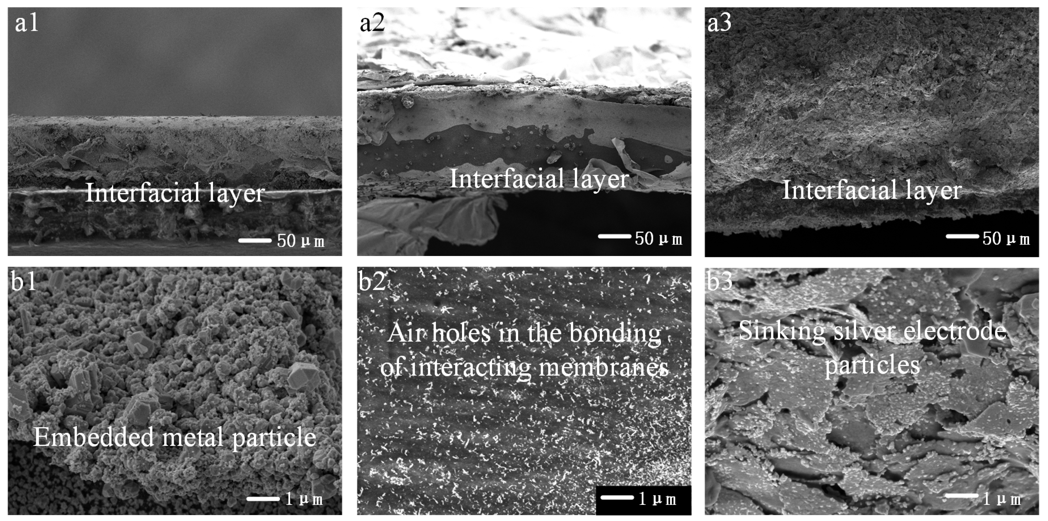
Figure 2, the electrode layer of chemically plated IPMC is unevenly fractured and the surface electrode quality is poor due to the uneven roughening and the reaction speed is difficult to regulate. In the deposition process, the silver particles are mainly concentrated in the glucose droplets. With the stirring of the equipment, the generated silver particles will be brought to various locations in the solution, and also, the silver layer with poor adhesion on the surface of the ion exchange membrane is adsorbed into the solution, resulting in the appearance of irregular cracks on the surface, and the cracks will be gradually decrease as the CP process proceeds.
According to SEM analysis, the HPCP fabricated layered energy storage electrode demonstrates strong adhesion to the membrane, forming an integrated structure. The electrode consists of a CP (chemical plating)-derived dispersed silver layer, reinforced with an additional continuous silver foil electrode serving as the conductive layer. The chemically synthesized silver nanoparticles penetrate into the membrane matrix, forming finely dispersed Ag particles, indicating that the ion reduction process facilitates the formation of a well-bonded interfacial layer. A distinct layered structure is observable at the interface, though the stratification gradually becomes less defined due to the diffusion of metallic silver within the interfacial region. The electrodes prepared by both the HPCP and CP methods have a chemical deposition process, and the electrodes that are not detached are presented as large, deposited electrode structures on the surface, and their adhesion is stronger than that of ordinary HP electrodes. Therefore, the driving effect of IPMC by HPCP method will be greatly improved compared with that of HP IPMC. HPCP IPMC electrode adds a complete silver foil electrode basis on the CP electrode, and the silver particles formed by the chemical reaction penetrate the inner membrane, generating a good laminar structure of the interfacial layer, and the metal monomers of the interfacial layer penetrate inward resulting in a gradual blurring of the laminar shape.

3.2. Study of the Physical Properties of Metal Electrodes IPMC

3.2.1. Metal Electrode IPMC Water Content and Water Absorption Test Analysis

  • IPMC water content test analysis
The water content of the ion exchange membrane has a large impact on both the conductivity and the internal ion migration rate of the IPMC [24]. Three kinds of IPMC with a width of 5 mm were tested for water content, and the mass before and after drying is shown in Table 1, and the water absorption rate is shown in 
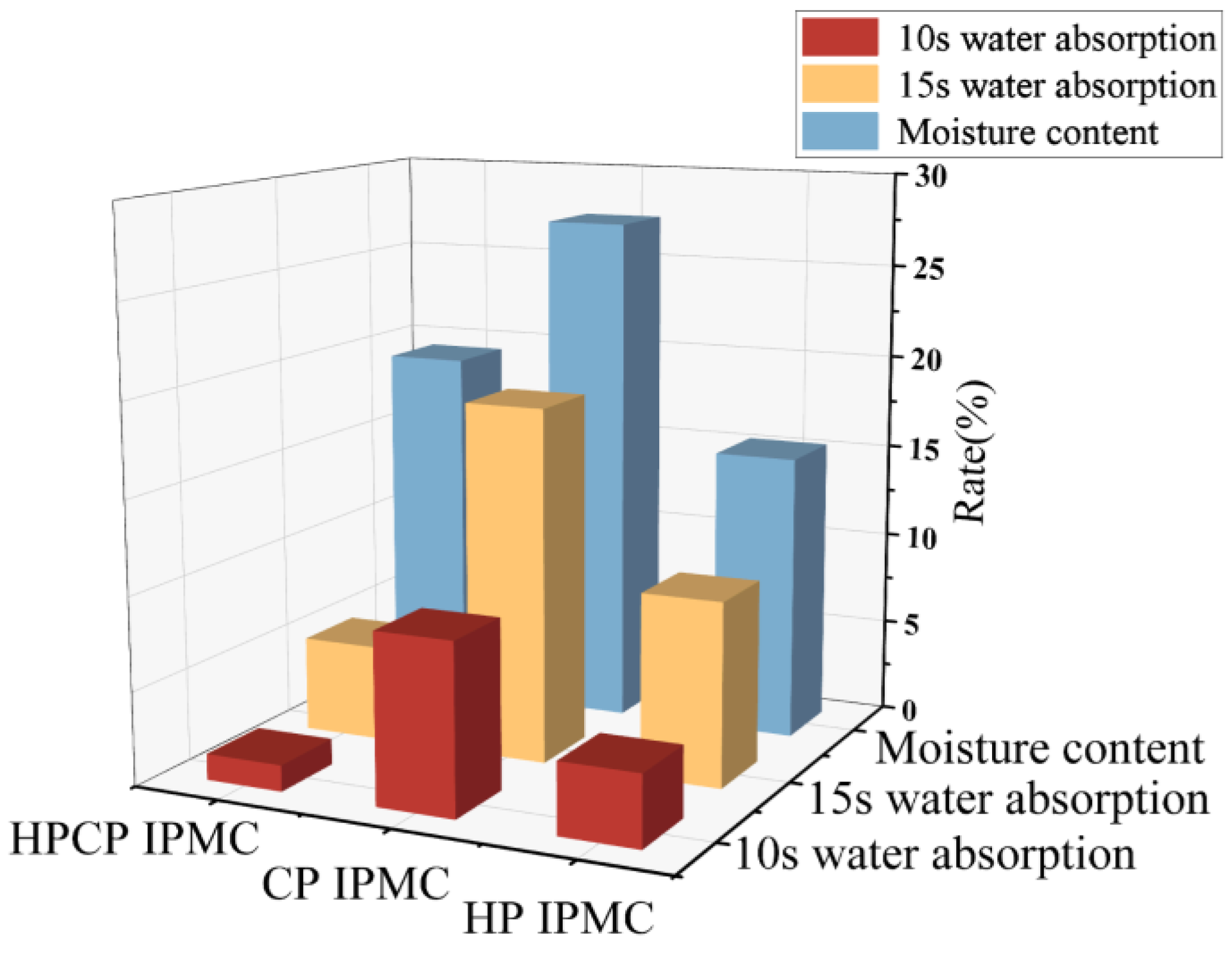
Figure 3. During the preparation process, a small number of tiny bubbles were mixed into the exchange membrane solution, and when the solution condensed, the bubbles stayed inside the exchange membrane, generating tiny pores that could store water. At the same time, the internal molecular chain is hydrophilic and connected with the sulfonic acid group, which can be combined with water molecules to form bound water. Therefore, an ion exchange membrane can store water molecules.
From Figure 3, it can be seen that the water content of chemically plated IPMC is higher, and the water content of the HP method and HPCP IPMC is lower. The reason for this phenomenon is that the HP method reduces the water storage capacity of IPMC. In the HP process, IPMC undergoes high temperature and pressure, and the membrane undergoes large deformation. Ion exchange membranes are thermoplastic and are not susceptible to plastic deformation after solidification. However, when using HP IPMC, the ion exchange membrane undergoes a dissolution reaction with the alcoholic binder and turns back into a viscous state. As the HP electrode needs high-temperature, high pressure, and continuous external load, the internal part of the pore space is closed, so that the structure of the IPMC after HP is compact, the water storage capacity is reduced, and the internal ion channel and water molecule pathway are suddenly reduced, resulting in the reduction of the ion migration rate, and the IPMC loses water easily during the driving process, which affects the driving performance. As the CP electrode preparation has been in the water environment for a long time, the electrode plating process will not affect the ion exchange membrane, and the ion reduction process can promote ion exchange and improve the water content of the ion exchange membrane.
2.
IPMC water absorption test analysis
IPMC is hydrophilic, so to show the hindering effect of the IPMC electrode on the penetration of water molecules, the water absorption rate of IPMC was tested. As shown in Table 2, the change of water absorption weight of IPMC after using for a while indicated the hindering effect of the electrode on the penetration of aqueous solution, and the weight of IPMC after 10 s and 15 s in water was tested, as shown in Figure 3.
As can be seen from Table 2, the permeability of IPMC by the CP method is better, and the permeability of IPMC by the HP method and HPCP method is worse. The main reason is that the CP IPMC electrode is made of loose silver powder accumulation, there are a large number of tiny cracks on the surface of the ion exchange membrane, and the membrane has not been extruded by external force, so the surrounding area is larger, with a large number of air holes and pore channels, and it can continuously absorb water. The two kinds of IPMC after HP have lower water absorption, which is mainly because the electrode layer is a dense silver foil electrode, and after wrapping, the pores of the electrode layer are too few and distributed around, so the surface cannot absorb water. However, during the preparation process, the pores of the ion exchange membrane were closed, which led to the low water absorption of IPMC. After the membrane was internally squeezed and deformed, the pores inside the ion exchange membrane were closed, the water molecule pathway was reduced, and the water absorption was slower.
In the early stage of the infiltration process, the ion exchange membrane and electrode pathway were not all opened, and the infiltration was gradually accelerated over time. Among the three kinds of IPMC, the electrode of the HP method changed more because the electrode layer on both sides was dense, some pores between the silver foils did not easily absorb water, the time into the water became longer, and some of the wrinkled electrodes warped to form a water pathway and increase the water absorption rate. During the experiment, the water absorption rate tends to stabilize and decrease after a gradual increase, and the water solution in the membrane is gradually saturated and overflows outwards, eventually forming a dynamic equilibrium.

3.2.2. Study of the Conductivity of Metal Electrodes IPMC

The electrode of IPMC acts as a conductive body and is the medium between external voltage excitation and internal ion transfer. Its electrode layer is a thin-film electrode, and it is chosen so that the square resistance property can be used to indicate the surface resistance [25], thus reflecting the conductivity of the IPMC electrode. The IPMC electrode preparation process involves the denaturation of the ion exchange membrane [
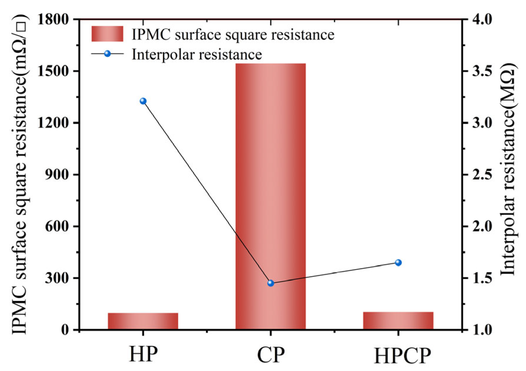
26], so it is necessary to test the resistance between its two poles to indicate the change like the ion exchange membrane. The IPMC samples were fabricated using three different processes (HP, CP, and HPCP), with six parallel samples prepared for each method and subjected to three cyclic tests. The HPCP IPMC samples exhibited a relative standard deviation (RSD) of 4.2%, which was lower than those of HP (7.84%) and CP (11.3%), demonstrating the superior stability of the HPCP process. As shown in Figure 4, the surface resistance of IPMC prepared by CP is large, and the surface resistance of IPMC by HP method and HPCP method is small. The reason for this phenomenon is that the chemically plated IPMC electrode is a deposition electrode, which is formed by the polymerization and precipitation of tiny silver particles, and the gap between the silver particles is much larger than the maximum attraction distance between the atoms, which results in the silver electrode being prone to delamination and cracking. The too-small gravitational force also leads to the loose structure of this electrode, and the electrode surface is prone to delamination or fracture when IPMC is deflected. Because of the high water content of the IPMC prepared by CP, the ion exchange membrane is highly susceptible to the swelling effect, which further aggravates the electrode cracking phenomenon and increases the surface resistance of the IPMC.
The size of the surface square resistance of the HP and HPCP electrodes is similar and the resistance between the HPCP electrodes is larger. This is because the surface electrodes of both preparation methods have silver foil layers, and they are single homogenized silver electrodes, so the resistance values are smaller and similar. During the preparation process of the HPCP electrode, the surface silver electrode will adhere to part of the leaked Nafion binder under high temperature and high pressure, i.e., the surface silver electrode will be bonded to the chemical silver plating layer to form a brand-new electrode layer, so the resistance is larger.
The inter-polar resistance test shows that the chemical-plated IPMC and HPCP IPMC have lower inter-polar resistance. The reason for this phenomenon is the difference in the interfacial layers of the three IPMC. Among them, the CP IPMC and HPCP IPMC have undergone an ion reduction process during the preparation process, and there are more silver monomer particles in the interfacial layer, which come into contact with each other to form an electronic pathway and directly lead to the inside of the ion exchange membrane. Increasing the contact area between the electrode and the ion exchange membrane improves the connection between the electrode and the ion exchange membrane; therefore, the inter-polar resistance of these two IPMC is smaller. Comparing the chemically plated IPMC with the HPCP IPMC, the inter-polar resistance is smaller due to the higher water content of the chemically plated IPMC, and the membrane damage during the preparation process is smaller, so the resistance is the smallest.
The three IPMC resistance tests were analyzed. The size of surface resistance reflects the quality of the IPMC surface electrode. The size of interpolar resistance reflects the damage of the electrode preparation to the ion exchange membrane and the quality of the interfacial layer, and a good interfacial layer improves the degree of bonding between the electrode and the exchange membrane. Comparing the three kinds of IPMC electrodes, the HPCP electrode has a better contact with the membrane, and its surface resistance is reduced by 14.9 times and the interpolar resistance is attenuated by 1.94 times compared with that of ordinary silver electrode IPMC. The formation of a good interfacial layer and the improvement of horizontal continuity and vertical continuity help to make the electric field inside the IPMC more uniform and the deflection process smoother.

3.3. Study of Energy Storage Performance of Metal Electrode IPMC

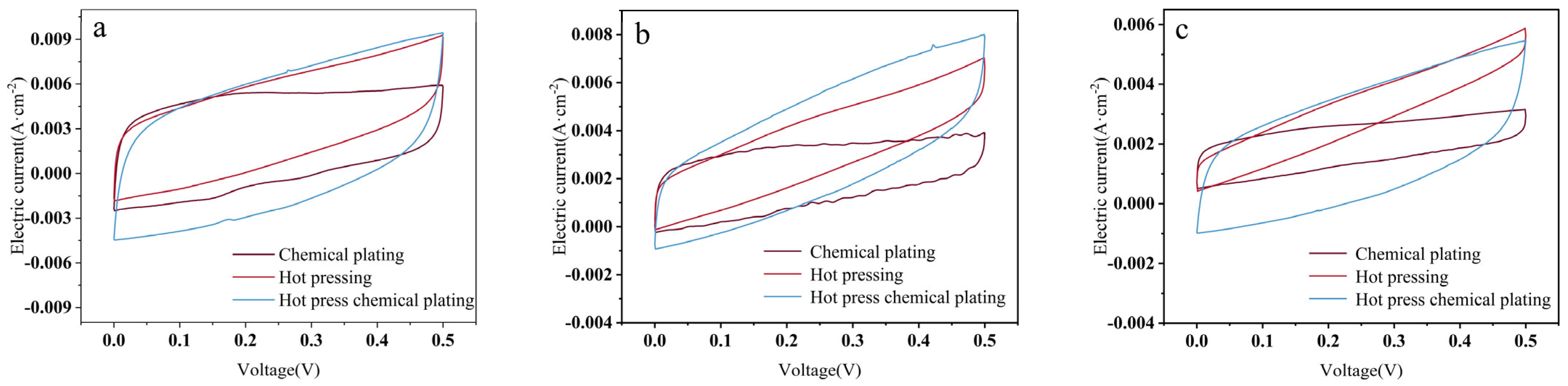
Cyclic voltammetry was performed on the IPMC with electrochemical windows of 0.5 V versus 1VCV curves [27] and scanning speeds set at 100 mV/s, 200 mV/s, and 500 mV/s [28]. The CV curves are shown in Figure 5 and Figure 6, and the specific capacitance comparison graph is shown in Figure 7.
As can be seen from Figure 5, the three CV plots are relatively smooth, so the ion exchange membrane of IPMC has a uniform texture and the electrode layer is plated uniformly and continuously. Among them, the CV curve of IPMC prepared by the CP method has ups and downs, which indicates that there are some defects in the electrode layer of this IPMC, and the CV curve fluctuates greatly because the continuity of the electrode, some defects in the electrode layer of this IPMC, and electrode prepared by CP method is poor, and the electrode is loose and unevenly coated. In the process of electrode preparation by the CP method, the silver particles produced by the chemical reaction are slowly deposited on the surface of the ion exchange membrane, the preparation speed is slow, and it is easy to produce a large number of oxidized silver particles; therefore, the IPMC will have ups and downs during the scanning process, that is, a small amount of redox reaction is carried out, and the fluctuation will be slowed down with the scanning process.
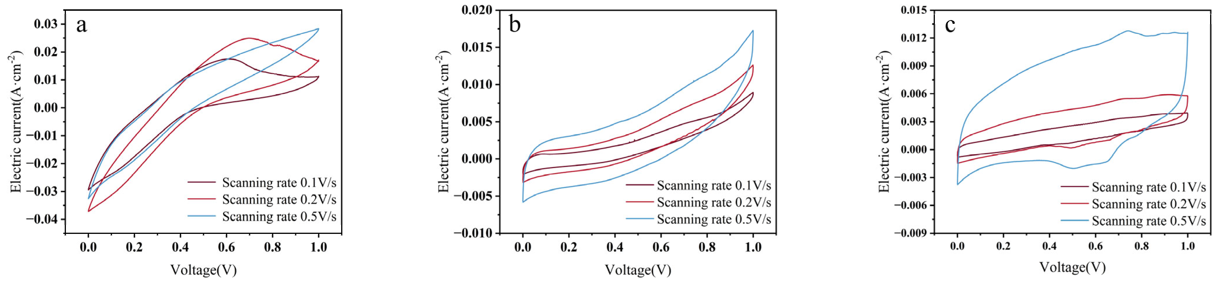
As shown in Figure 6, the IPMC prepared by the HPCP method exhibits the most outstanding double-layer capacitance characteristics, with its CV curve presenting a nearly perfect rectangular shape [29]. This superiority stems from its unique multi-layer composite structure: the hot-pressed silver foil ensures the horizontal conductivity of the electrode, the CP silver layer forms vertical conductive channels through the penetration of ion-exchange membranes, constructing a three-dimensional charge transfer network [30,31]. While this structure enhances electrode continuity and energy storage capacity, it concurrently increases the thickness of the electrode layer. At elevated scan rates, the required charge transfer must occur within a reduced timeframe. However, the thickened electrode layer introduces greater charge transfer resistance, impeding timely charge response and consequently manifesting as capacitance attenuation. This phenomenon becomes particularly pronounced under high scan rate conditions. In contrast, the HP electrode, due to the high-temperature and high-pressure process, causes membrane structure deformation and a significant reduction in water content, resulting in ion transport obstruction. The CP electrode, on the other hand, due to the inherent non-uniformity of the chemical plating process, has a large number of micron-level cracks and silver oxide impurities on its surface, causing obvious fluctuations in the CV curve, indicating defects and poor continuity in its electrode layer. These defects may become more pronounced under high-voltage conditions, where localized micro-scale electrode regions may delaminate due to electrical stress, resulting in the formation of internal microvoids. This further deteriorates the contact efficiency between the electrode and the ion-exchange membrane. Such structural non-uniformity can induce unstable fluctuations in capacitance. These results clearly demonstrate that the continuity of the electrode and the interface structure are the key factors determining the energy storage performance of IPMC [32]. The HPCP process, by constructing a hierarchical structure of “dense conductive layer—porous interface layer”, shows the best double-layer capacitance and energy storage performance, successfully achieving the synergistic optimization of electron/ion transport.
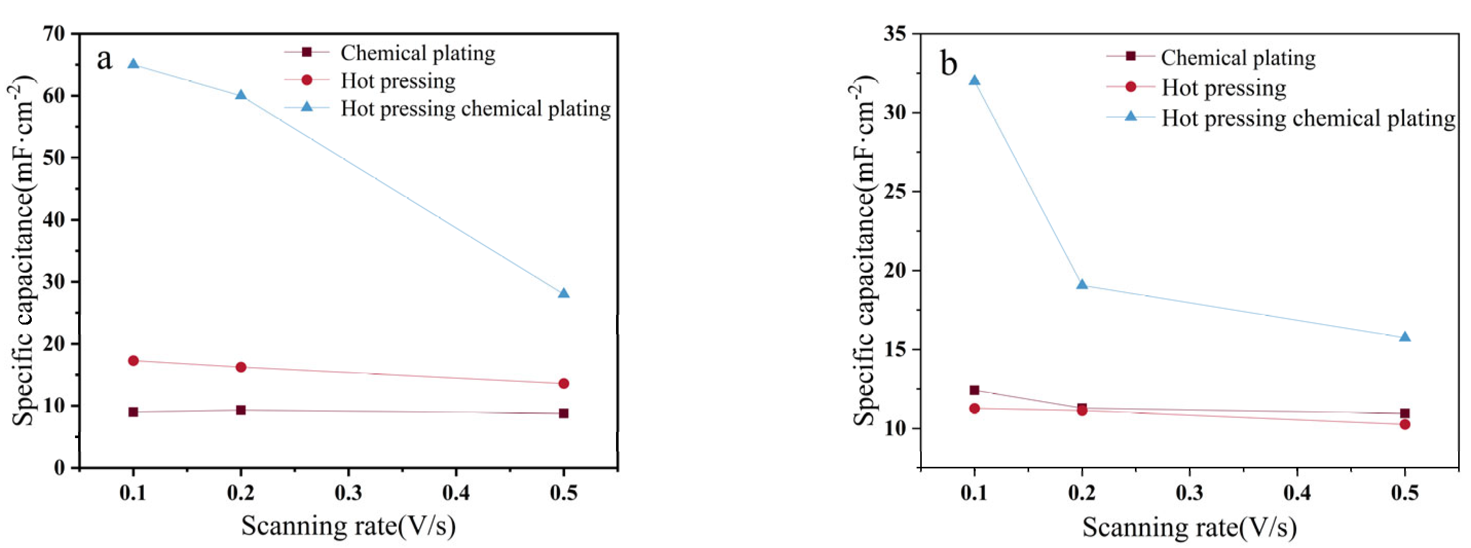
The specific capacitance of HPCP IPMC decreases faster during the scanning speed increase, and the chemical-plated IPMC shows a transient rise in the specific capacitance in the 1 V interval, which is investigated:
  • The reason why the specific capacitance of HPCP IPMC decreases faster is that the electrode layer is too thick. HPCP IPMC is a seven-layer structure, and there are two layers of CP electrodes between the electrodes and the ion exchange membrane, as well as two layers of the Nafion bonding layer, which makes the internal energy storage of IPMC high. However, the IPMC surface charge conduction resistance to the interior is greater, the transfer rate is slower, and the charge will be lost. When the scanning speed is increased, the IPMC electrode layer and the substance inside the film react slower and cannot react fully, and the scanning speed is increased faster than the capacitance is decreased. The second reason for the electrode is that it is not uniform. The HPCP preparation process requires CP, so there are some of the shortcomings of CP preparation, such as the IPMC inner layer electrode not being uniform, causing some of the tiny electrodes in the high-voltage impact under the capacitance to produce separation, the formation of a small cavity inside the membrane, resulting in the reduction of electrode adhesion. The cavity will lead to the weakening of the electrodes and the contact between the ion exchange membrane, then the capacitance decreases more quickly.
  • The silver electrode coating process is affected by external factors, resulting in uneven electrodes and unstable connections between the electrode and the ion exchange membrane, and the CP is affected by the reaction rate and the degree of roughening of the surface of the ion exchange membrane during deposition. Before a CP, the surface of the ion exchange membrane is roughened, and during the chemical deposition process, silver particles will be deposited inside the roughened ‘grooves’ to improve the adhesion ability. If the roughening effect is poor or omitted during the preparation process, the electrode layer of the IPMC will be easily detached, resulting in electrode layer fracture. In the preparation process, the roughing process is not easy to control, the surface grooves are not uniform after roughing, and the electrode layer is easy to change after the current impact, resulting in a sudden change in the specific capacitance of IPMC. In addition, the reaction rate will also affect the quality of the electrode layer. In the CP deposition experiments, the reaction of the initial silver ammonia solution concentration is higher, and the reaction rate is faster. The result is that the silver particles are deposited too quickly, and the silver particles are not firmly deposited in the ‘gullies’ after roughening, or cannot fill the ‘gullies’, forming cavities and leading to poor electrode quality.
In summary, the HPCP method presents a large energy storage performance due to its unique structure, which is 2.58 times higher than that of the common chemical silver-plated electrodes under the scanning speed of 100 mV/s. Therefore, the corresponding actuator has better driving performance. From this experiment, it can be seen that the special energy storage structure as well as the energy storage material can improve the energy storage performance of IPMC.

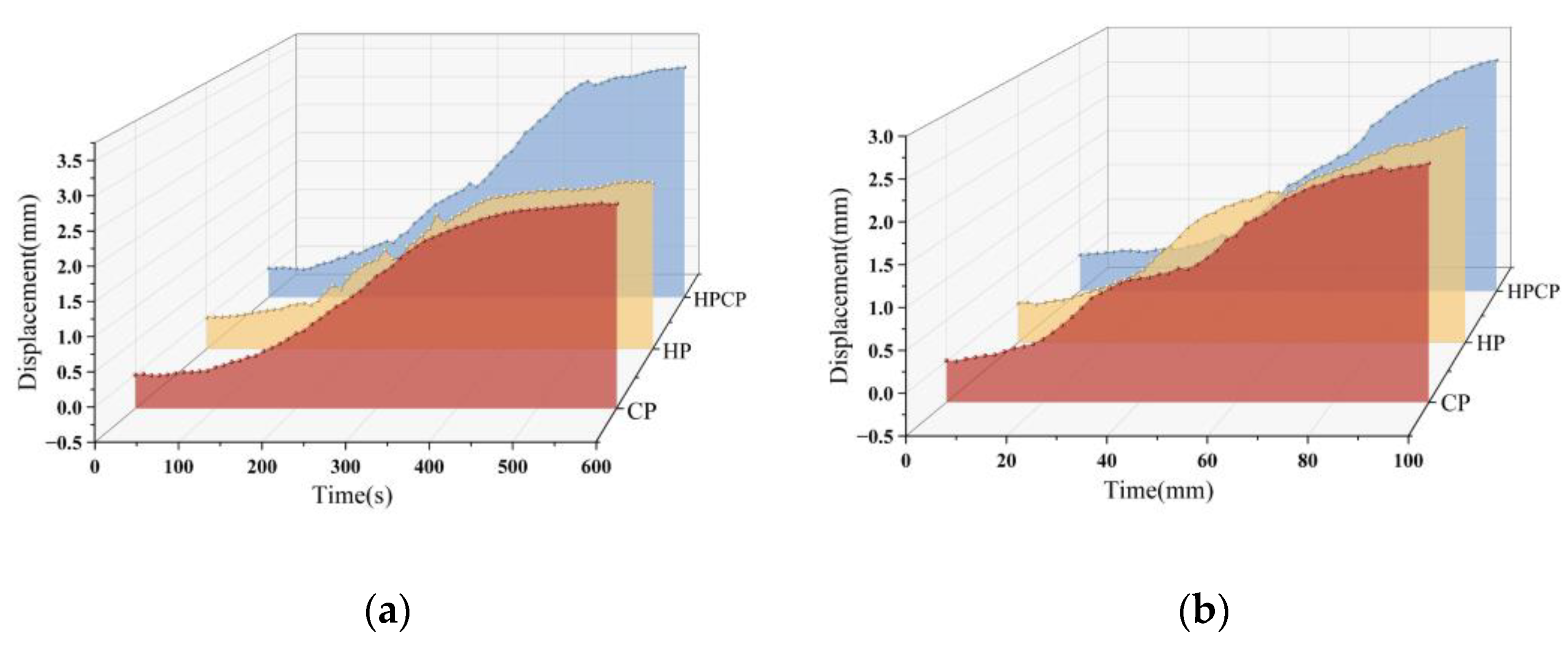
3.3.1. Study on the Effect of IPMC Energy Storage Performance of Metal Electrodes on Output Displacement

IPMC was subjected to tip displacement actuation performance tests to analyze the displacement response of three silver electrodes, chemically plated IPMC, HP IPMC, and HPCP IPMC, at 5 V and 3 V. The displacement map is obtained as shown in Figure 8, and the ultimate displacement and strain are shown in Table 3.
In the displacement performance test, there is a big difference in the displacement deflection of the three IPMC in the 3 V and 600 s test cases, while in the 5 V and 100 s cases, there is not a big gap. And, in the case of the 100 s, the three curves still have a rising trend. It can be seen that the IPMC did not reach the expected value at 100 s. It reached the limit value, and gradually produced a rebound in the case of 3 V. Among the three kinds of IPMC, the HPCP IPMC is much higher than the other two in the case of 3 V. In the 5 V case, the IPMC with high capacitance deflects at a slower rate instead and has a longer charging time. It can be concluded that the limit deflection of IPMC is more related to the size of capacitance, and the deflection rate is more related to capacitance, interface layer, and water content.
The energy storage and actuation performance of the HPCP IPMC demonstrate significant improvements compared to conventional methods and existing studies. Liu [33] proposed a gradient model for IPMC, reporting a typical specific capacitance range of 10–20 mF/cm2. In contrast, the HPCP method achieves a markedly higher specific capacitance of 31.99 mF/cm2, highlighting the substantial advantages of its laminated electrode structure in energy storage. This performance also surpasses that of nanocomposite or sputtered electrodes investigated by Sadat and Hasani, which exhibited specific capacitances of 20–30 mF/cm2. Notably, the HPCP method attains superior capacitance while avoiding the complex processes and high costs associated with these advanced electrode fabrication techniques.
In terms of actuation performance, the HPCP IPMC exhibits a maximum displacement of 3.44 mm and a strain of 5.09% under 3 V excitation, significantly outperforming both HP (2.17 mm, 1.62%) and CP (2.54 mm, 4.58%) methods. This result also exceeds the actuation performance reported by Wang [34] for IPMC-driven robotic fish, where displacements ranged between 2 and 3 mm. The enhanced performance of the HPCP IPMC can be attributed to its optimized electrode structure, which improves both energy storage capacity and electromechanical coupling efficiency. These findings underscore the potential of the HPCP method for developing high-performance IPMC actuators in practical applications.
The displacement deflection of IPMC mainly exists in two processes. At the beginning of the energization, IPMC is first charged to the electrode layer and then flows towards the interior at the end. The reason for the long charging time of HPCP IPMC is the thicker electrode layer. The energy storage performance plays a major role in driving. After the electrode layer is fully charged, the link surface with the ion exchange membrane gradually attracts ions to form a double charge effect, at which time the electrode is charged again to achieve charge conservation. The quality of the interface layer and the energy storage performance both play a major role in the drive. HPCP IPMC can exhibit greater strain, i.e., greater deformation on both sides of the exchange membrane, and have better output performance. Therefore, the strain can somewhat approximately replace the displacement driving ability of IPMC.

3.3.2. Study of the Effect of IPMC Energy Storage Properties on Mechanical Properties of Metal Electrodes

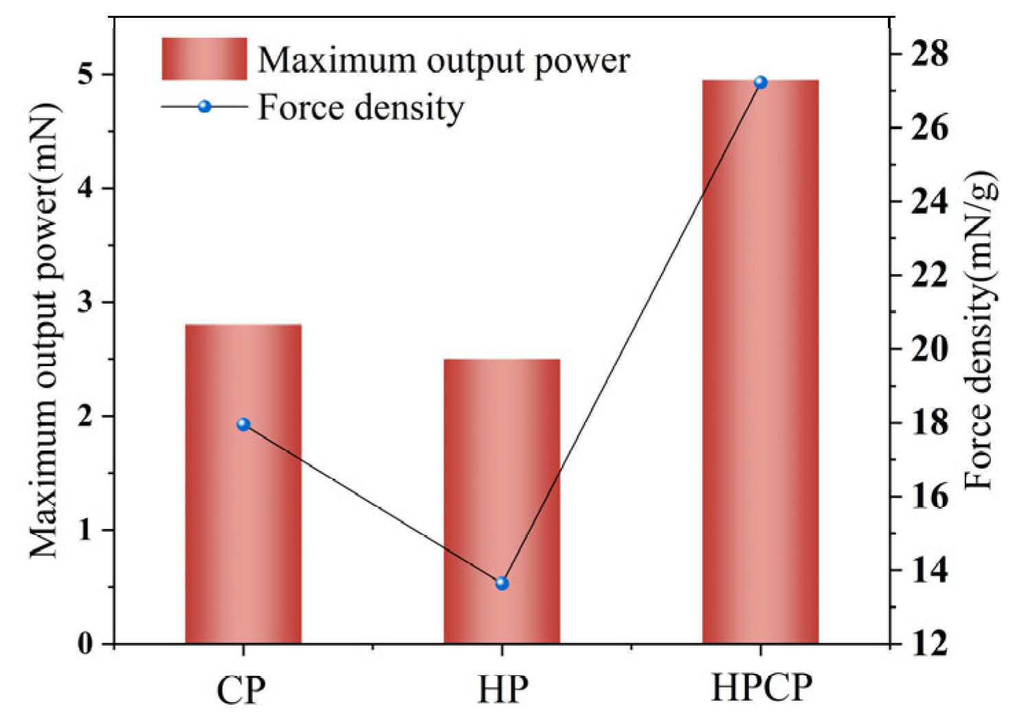
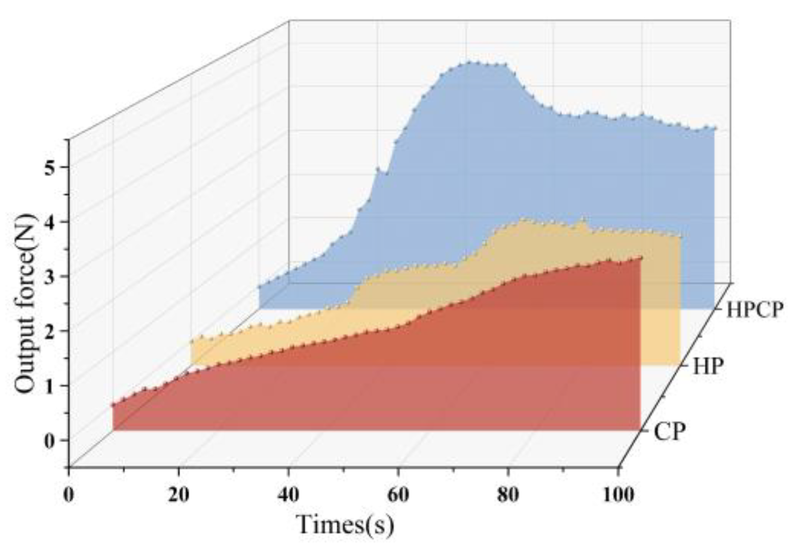
The mechanical response of the IPMC is tested and the results are shown in Figure 9 and Figure 10. The optimum response is 10% taken downwards from the maximum value of the output force, which demonstrates that the IPMC is maintained at the maximum output force, as shown in Figure 11.
From Figure 9 and Figure 10, it can be seen that the IPMC produces displacement deformation at the tip under external voltage, and with the increase of the energization time and voltage intensity, the IPMC deflection intensifies, and some of the IPMC gradually become more and more displacements and rebound phenomenon during the deformation process, which is in line with the expected results.
Comparing the mechanical output, the mechanical properties of IPMC prepared by the HPCP method are stronger than the other two, and the deflection process is more stable without large ups and downs, while the output force and output force density of IPMC prepared by the HP method are lower. This is because the IPMC prepared by the HPCP method has a stronger energy storage performance and the internal electric field is more stable. The IPMC forms a uniform electric field between the two levels after the current is passed through it, and the migrating anions and cations move towards the internal applied electric field. The IPMC prepared by the HPCP method has a layered structure, forming a small capacitor. After energization, the electrode is energized first, and an electric field is formed in the vertical direction. When the current circulates in the horizontal direction of the electrode, the farther the distance, the lower the potential, and the capacitor formed by the lamellar structure supplements electrons for it, so the deflection process is more stable.
In the mechanical test, the performance of single HP and CP IPMC is poor, while the performance of HPCP IPMC is good. The reason for this phenomenon is that in HP IPMC, the electrodes are complete silver electrodes, which have better electrode coherence in the horizontal direction and good electron conduction ability in the horizontal direction. However, the bonding in the vertical direction is poor and easy to fall off, so the vertical conductivity is poor. In chemically plated IPMC, the electrode is a loose powder stacked electrode, there is a good interfacial layer, with good vertical electron conduction capability, but the horizontal direction electrode is easy to crack, and the conductivity is poor. In contrast, HPCP IPMC has an intermediate layer of CP electrodes in the vertical direction, which ensures the conduction of surface charge to the surface of the ion exchange membrane, and conducts electricity horizontally using a low-resistance HP silver electrode, which ensures the continuity of the electrodes. A comparison of the mechanical properties of the chemically plated IPMC electrode and the HP IPMC electrode shows that the chemically plated IPMC electrode has better performance, which is due to the reduction of the internal pores of the IPMC under high temperature and high pressure in the preparation process, which reduces the water content of the IPMC and makes the content of hydrated cations inside the IPMC decrease. At the same time, the distance between the two levels of IPMC is reduced after high pressure, and the anions and cations are closer together after deflection, which makes it easy to produce a rebound phenomenon.
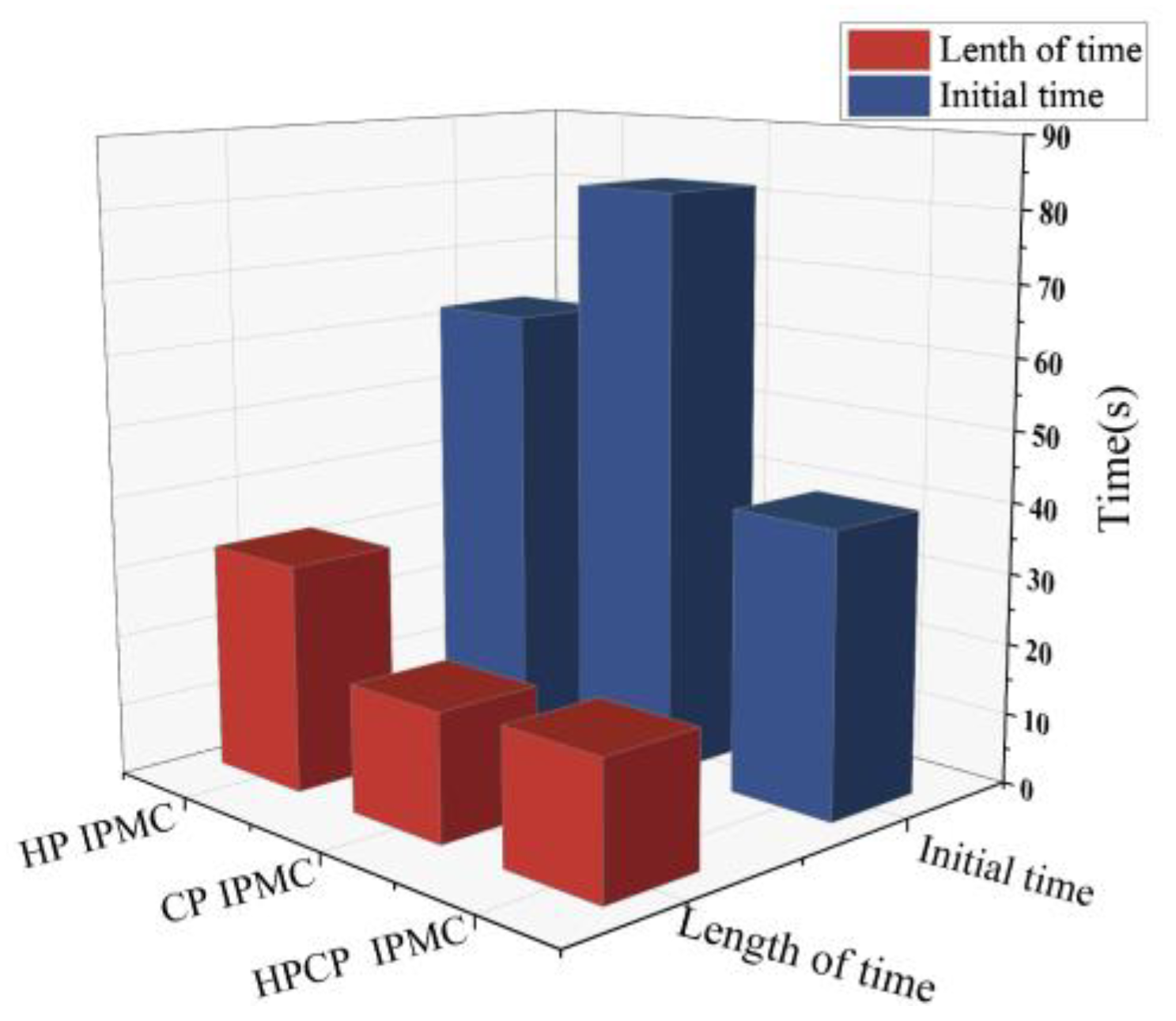
Comparing the single electrode retention capability, the HP IPMC retention capability is better, and the HPCP IPMC reaches the maximum output force earlier, i.e., the fastest response. This is due to the poor and relatively stable performance of HP IPMC. Fewer water molecules are in the IPMC membrane, and the deflection and rebound of IPMC are less sensitive to the current. As the experiment proceeds, the IPMC is susceptible to its water content, in which the chemically plated IPMC has a higher water content and the electrodes are loose and susceptible. The water molecules of this IPMC are easy to volatilize when subjected to an external force and when a current is passed through it, so the retention ability is poor and the response is slower. After HP, the electrodes are denser and therefore have a higher retention capacity. The internal stable large electric field of the HPCP IPMC promotes ion movement and recovery, and the stabilization value is reached earlier.

4. Conclusions

In this study, three silver electrodes with different structures of IPMC were prepared by using traditional electrode preparation processes (HP and CP) and new electrode preparation processes (HPCP), characterization tests, physical property tests, energy storage performance tests, and driving performance tests were carried out. The differences in IPMC electrode structures between the different electrode preparation processes and the effects of electrode preparation processes and structures on the energy storage performance and driving performance of IPMC were investigated.
Conformal characterization test results show that the combination between the IPMC electrode and ion exchange membrane of the HPCP method is dense, the interface layer has no porosity, and the electrode plating effect is better, in which the HPCP electrode maintains better continuity in both horizontal and vertical directions. The tests of the physical and electrochemical properties of IPMC with different electrode structures showed that the electrode structure affected the water absorption, conductivity, and energy storage performance of IPMC. With the improvement of the continuity of the electrode layer, the water absorption rate gradually decreases, that is, the exchange of water molecules between the ion exchange membrane layer and the external environment is reduced. With the improvement of the horizontal continuity of the electrode, the surface resistance of the IPMC gradually decreases. With the improvement of the vertical continuity of the electrode, the inter-polar resistance of the IPMC gradually decreases. Among them, the laminar electrode IPMC has high conductivity in both horizontal and vertical directions, with an inter-polar resistance of 1.653 MΩ and a surface square resistance of 103.62 mΩ/□. The energy storage performance of the IPMC formed by HPCP of the layered electrode is better, with a specific capacitance of 31.99 mF·cm2 at an electrochemical window of 0.5 V and a scanning rate of 100 mV/s, indicating that the layered electrode structure can improve the energy storage performance of the IPMC. The driving performance test results show that the driving performance of the IPMC formed by the laminated electrode of the HPCP method is better, and the ultimate displacement of the IPMC formed by the HPCP method is 3.44 mm at 7 mm at 600 s under the external excitation of 3 V, and the ultimate strain is 5.09%, and the maximum output force reaches 4.95 mN under the external excitation of 5 V, which is much higher than that of the other three kinds of IPMC. Comparative analysis of the results shows that the specific capacitance is 31.99 mF·cm2 under the scanning speed of 100 mV/s. Comparison and analysis with the electrochemical test results show that the ultimate deflection and output force of the IPMC gradually increase with the increase of specific capacitance, and the enhancement of the energy storage performance can improve the driving performance of the IPMC.

Author Contributions

Conceptualization, J.Z.; methodology, Y.D.; validation, Z.Z.; formal analysis, D.Y.; investigation, S.Z.; resources, M.J.; writing—original draft preparation, J.Z.; writing—review and editing, Y.D.; funding acquisition, J.Z. All authors have read and agreed to the published version of the manuscript.

Funding

The authors were supported by the Excellent Young Teachers Basic Research Support Program of Heilongjiang Province (YQJH2023257) in the writing and publication of this paper.

Institutional Review Board Statement

Not applicable.

Informed Consent Statement

Not applicable.

Data Availability Statement

The data supporting the results reported in this study can be made available upon reasonable request from the corresponding author. The data underlying the results presented in this paper are not publicly available at this time but may be obtained from the authors upon reasonable request.

Conflicts of Interest

The authors declare no conflicts of interest.

References

  1. Hao, M.; Wang, Y.; Zhu, Z.; He, Q.; Zhu, D.; Luo, M. A compact review of IPMC as soft actuator and sensor: Current trends, challenges, and potential solutions from our recent work. Front. Robot. AI 2019, 6, 129. [Google Scholar] [CrossRef] [PubMed]
  2. Nguyen Duy, V.; Kim, H.M. A study of the movement, structural stability, and electrical performance for harvesting ocean kinetic energy based on IPMC material. Processes 2020, 8, 641. [Google Scholar] [CrossRef]
  3. Pawar, M.S. Advancement of a Wall Climbing Robot for Various Applications. Int. J. Res. Eng. Technol. 2016, 5, 9–11. [Google Scholar]
  4. Ye, Z.Z.; Hou, P.Q.; Chen, Z. 2D Maneuverable Robotic Fish Propelled by Multiple Ionic Polymer-metal Composite Artificial Fins. Int. J. Intell. Robot. Appl. 2017, 1, 195–208. [Google Scholar] [CrossRef]
  5. Guo, S.; Shi, L.; Ye, X.; Li, L. A New Jellyfish Type of Underwater Microrobot. In Proceedings of the IEEE 2007 International Conference on Mechatronics and Automation, Harbin, China, 5–8 August 2007; pp. 509–514. [Google Scholar]
  6. Ma, Y.J.; Li, X.Y.; Liang, B.; Du, Y.; Liu, J.; Yang, S. Development and Motion Mode Analysis of IPMC Bionic Jellyfish Based on App Bluetooth Remote Control. IOP Conf. Ser. Earth Environ. Sci. 2019, 252, 45–57. [Google Scholar] [CrossRef]
  7. Bernat, J.; Gajewski, P.; Kołota, J.; Marcinkowska, A. Review of Soft Actuators Controlled with Electrical Stimuli: IPMC, DEAP, and MRE. Appl. Sci. 2023, 13, 1651. [Google Scholar] [CrossRef]
  8. Wang, Z.; Dong, C.; Zhang, Z.; Tian, Q.; Sun, A.; Yuan, L.; Zhang, L. Review of multi-fin propulsion and functional materials of underwater bionic robotic fish. Proc. Inst. Mech. Eng. Part C J. Mech. Eng. Sci. 2022, 236, 7350–7367. [Google Scholar] [CrossRef]
  9. Nam, D.; Ahn, K.K. Design of an IPMC Diaphragm for Micropump Application. Sens. Actuators A Phys. 2012, 187, 174–182. [Google Scholar] [CrossRef]
  10. Qin, L.G.; Gong, C.Y.; Hafezi, M.; Mawignon, F.J.; Huang, X.; Zeng, Q.; Zhang, Y.; Dong, G. Carboxylic Multi-Walled Carbon Nanotubes as Reinforcing Fillers in Ionic Polymer-Metal Composite Actuators with Enhanced Driving Performance. Adv. Eng. Mater. 2022, 24, 2200008. [Google Scholar] [CrossRef]
  11. Koichi, S.; Hiroyuki, N.; Kinji, A.; Tetsuya, H. Applying IPMC to Soft Robots. In Electroactive Polymer Actuators and Devices (EAPAD) XXII; SPIE: Bellingham, WA, USA, 2020; Volume 11375, pp. 38–46. [Google Scholar]
  12. Wang, H.; Yang, L.; Yang, Y.; Zhang, D.; Tian, A. Highly flexible, large-deformation ionic polymer metal composites for artificial muscles: Fabrication, properties, applications, and prospects. Chem. Eng. J. 2023, 469, 143976. [Google Scholar] [CrossRef]
  13. Hosseini, S.S.; Yamini, B.; Ichkitidze, L.; Asadi, M.; Fernandez, J.; Gholampour, S. Enhanced Ionic Polymer-Metal Composites with Nanocomposite Electrodes for Restoring Eyelid Movement of Patients with Ptosis. Nanomaterials 2023, 13, 473. [Google Scholar] [CrossRef] [PubMed]
  14. Hasani, M.; Alaei, A.; Mousavi, M.S.S.; Esmaeili, E.; Kolahdouz, M.; Naeini, V.F.; Masnadi-Shirazi, M. Fabrication of Ionic Polymer-metal Composite Actuators with Durable and Quality-enhanced Sputtered Electrodes. J. Micromech. Microeng. 2019, 29, 085008. [Google Scholar] [CrossRef]
  15. Truszkowska, A.; Porfiri, M. Actuation of Ionic Polymer-metal Composites with Alkali Metal Counterions-a Molecular Dynamics Study. Eng. Res. Express 2022, 4, 025031. [Google Scholar] [CrossRef]
  16. Zhang, W.; Mou, J.; Gu, Y. Recent Developments About IPMCs (Ionic Polymer-Metal) Composites: A Review of Performances for Different Conditions. Fluid Dyn. Mater. Process. 2018, 14, 243–258. [Google Scholar] [CrossRef]
  17. Hall, P.J.; Mirzaeian, M.; Fletcher, S.I.; Sillars, F.B.; Rennie, A.J.R.; Shitta-Bey, G.O.; Wilson, G.; Cruden, A.; Carter, R. Energy storage in electrochemical capacitors: Designing functional materials to improve performance. Energy Environ. Sci. 2010, 3, 1238–1251. [Google Scholar] [CrossRef]
  18. Yang, L.; Zhang, D.S.; Zhang, X.N.; Tian, A.; Hui, X.; Yang, J. Fabrication of Cu/Nafion-Based Ionic Polymer Metal Composites by Electroless Plating Method. Integr. Ferroelectr. 2020, 209, 48–57. [Google Scholar] [CrossRef]
  19. Kim, S.S.; Jeon, J.H.; Kee, C.D. Electro-active Hybrid Actuators Based on Freeze-Dried Bacterial Cellulose and PEDOT: PSS. Smart Mater. Struct. 2013, 22, 085026. [Google Scholar] [CrossRef]
  20. Mousavi, M.S.S.; Manteghi, F.; Kolahdouz, M. Enhanced Actuation Application of Nafion-ZnO Nanoparticles Doped Sheet as Ionic Polymer Metal Composite (IPMC); Dopant Piezoelectric Effect. Bull. Mater. Sci. 2020, 46, 94. [Google Scholar] [CrossRef]
  21. Zhang, X.J.; Wang, M.; Li, M.H.; Zhang, M.; Zhang, C. Fabrication of Macroporous Nafion Membrane from Silica Crystal for Ionic Polymer-Metal Composite Actuator. Processes 2020, 8, 94. [Google Scholar] [CrossRef]
  22. Bülter, H.; Denuault, G.; Mátéfi-Tempfli, S.; Mátéfi-Tempfli, M.; Dosche, C.; Wittstock, G. Electrochemical analysis of nanostructured iron oxides using cyclic voltammetry and scanning electrochemical microscopy. Electrochim. Acta 2016, 222, 1326–1334. [Google Scholar] [CrossRef]
  23. Wang, G.; Sun, Y.; Ji, A.; Yin, G.; Ge, H.; Liu, X.; Tong, X.; Yu, M. Review on the Research Progress and Application of IPMC Sensors. J. Bionic Eng. 2024, 21, 2687–2716. [Google Scholar] [CrossRef]
  24. He, Q.; Yu, M.; Song, L.; Ding, H.; Zhang, X.; Dai, Z. Experimental study and model analysis of the performance of IPMC membranes with various thickness. J. Bionic Eng. 2011, 8, 77–85. [Google Scholar] [CrossRef]
  25. Peng, S.; Jin, Z.; Peng, M.; Zhang, D.; Shi, J.; Niu, J.; Wang, X.; Wang, S.; Li, M.; Liu, X.; et al. The sheet resistance of graphene under contact and its effect on the derived specific contact resistivity. Carbon 2015, 82, 500–505. [Google Scholar] [CrossRef]
  26. Roper, D.K.; Lightfoot, E.N. Separation of biomolecules using adsorptive membranes. J. Chromatogr. A 1995, 702, 3–26. [Google Scholar] [CrossRef]
  27. Aoyagi, W.; Omiya, M. Mechanical and electrochemical properties of an IPMC actuator with palladium electrodes in acid and alkaline solutions. Smart Mater. Struct. 2013, 22, 055028. [Google Scholar] [CrossRef]
  28. Wang, X.W.; Zhu, Q.Q.; Wang, X.E.; Zhang, H.C.; Zhang, J.J.; Wang, L.F. Structural and electrochemical properties of La0.85Sr0.15MnO3 powder as an electrode material for supercapacitor. J. Alloys Compd. 2016, 675, 195–200. [Google Scholar] [CrossRef]
  29. Wu, J. Understanding the electric double-layer structure, capacitance, and charging dynamics. Chem. Rev. 2022, 122, 10821–10859. [Google Scholar] [CrossRef]
  30. Minakshi, M.; Mujeeb, A.; Whale, J.; Evans, R.; Aughterson, R.; Shinde, P.A.; Ariga, K.; Shrestha, L.K. Synthesis of porous carbon honeycomb structures derived from hemp for hybrid supercapacitors with improved electrochemistry. ChemPlusChem 2024, 89, e202400408. [Google Scholar] [CrossRef]
  31. Minakshi, M.; Samayamanthry, A.; Whale, J.; Aughterson, R.; Shinde, P.A.; Ariga, K.; Kumar Shrestha, L. Containing Activated Carbon Derived from Natural Honeydew Peel Powers Aqueous Supercapacitors. Chem. Asian J. 2024, 19, e202400622. [Google Scholar] [CrossRef]
  32. Miller, E.E.; Hua, Y.; Tezel, F.H. Materials for energy storage: Review of electrode materials and methods of increasing capacitance for supercapacitors. J. Energy Storage 2018, 20, 30–40. [Google Scholar] [CrossRef]
  33. Liu, H.G.; Xiong, K.; Wang, M. A Gradient Model for Young’s Modulus and Surface Electrode Resistance of Ionic Polymer-Metal Composite. Acta Mech. Solida Sin. 2019, 32, 754–766. [Google Scholar] [CrossRef]
  34. Wang, T.M.; Shen, Q.; Wen, L.; Liang, J.H. On the Thrust Performance of an Ionic Polymer-metal Composite Actuated Robotic Fish: Modeling and Experimental Investigation. Sci. China Technol. Sci. 2012, 55, 3359–3369. [Google Scholar] [CrossRef]
Figure 1. Schematic diagram of the electrochemical workstation used for cyclic voltammetry tests.
Coatings 15 00577 g001
Figure 2. SEM scans of IPMC with different electrode plating methods: (a1a3) cross-sectional morphology of HPCP method, HP method, and CP method, (b1b3) surface topography of HPCP method, HP method, and CP method.
Coatings 15 00577 g002
Figure 3. Water content and water absorption for different electrode processes.
Coatings 15 00577 g003
Figure 4. Interpolar resistance and surface square resistance of electrodes of different processes.
Coatings 15 00577 g004
Figure 5. CV curve of electrochemical window 0.5 V: (a) scanning rate 100 mV/s, (b) scanning rate 200 mV/s, (c) scanning rate 500 mV/s.
Coatings 15 00577 g005
Figure 6. CV curve of electrochemical window 1 V: (a) CV curve of HPCP, (b) CV curve of HP, (c) CV curve of CP.
Coatings 15 00577 g006
Figure 7. Comparison diagram of specific capacitance: (a) comparative analysis of 1 V capacitors for electrochemical windows, (b) comparative analysis of 0.5 V capacitors for electrochemical windows.
Coatings 15 00577 g007
Figure 8. Output displacement of IPMC with different electrode coating methods: (a) 3 V displacement diagram, (b) 5 V displacement diagram.
Coatings 15 00577 g008
Figure 9. IPMC maximum output force and force density.
Coatings 15 00577 g009
Figure 10. Output force test diagram.
Coatings 15 00577 g010
Figure 11. IPMC holding capacity.
Coatings 15 00577 g011
Table 1. Quality of IPMC before and after drying for different electrode plating processes.
TypesInitial Weight (g)Ultimate Weight (g)Lengths (mm)
HP IPMC0.1570.13325.5
CP IPMC0.1970.14330.3
HPCP IPMC0.1690.13827.8
Table 2. Quality of IPMC before and after water absorption for different electrode plating methods.
TypesDry Weight (g)10 s Water Absorption Weight (g)15 s Water Absorption Weight (g)
HP IPMC0.1330.1380.146
CP IPMC0.1430.1560.170
HPCP IPMC0.1380.1400.145
Table 3. IPMC ultimate displacement and strain.
CPHPHPCP
Displacement (mm)2.542.173.44
Strains (%)4.581.625.09
Disclaimer/Publisher’s Note: The statements, opinions and data contained in all publications are solely those of the individual author(s) and contributor(s) and not of MDPI and/or the editor(s). MDPI and/or the editor(s) disclaim responsibility for any injury to people or property resulting from any ideas, methods, instructions or products referred to in the content.

