Article

Preparation and Characterization of Composite Hydrogen Barrier Coatings with (Graphene–Epoxy Resin)/(Silicon Carbide–Epoxy Resin)/(Graphene–Epoxy Resin) Sandwich Structures

School of Materials Science & Engineering, Xi’an University of Technology, No. 5, Jinhua South Road, Beilin District, Xi’an 710048, China
*
Author to whom correspondence should be addressed.
Coatings 2025, 15(5), 518; https://doi.org/10.3390/coatings15050518
Submission received: 31 March 2025 / Revised: 24 April 2025 / Accepted: 24 April 2025 / Published: 25 April 2025

Abstract

:
How to solve hydrogen embrittlement (HE) is a key issue that urgently needs to be addressed in the hydrogen energy industry. The use of hydrogen barrier coatings can effectively reduce the occurrence of HE. In this article, we utilized the epoxy resin (ER) as the base coating and the graphene (GN) and the silicon carbide (SiC) as the additives to prepare the (GN-ER)/(SiC-ER)/(GN-ER) sandwich structure composite hydrogen barrier coatings by the spin coating method and investigated the effect of coating composite ways on the hydrogen barrier performance. The GN-ER and the SiC-ER are used as the hydrogen barrier layer and the hydrogen capture layer, respectively, in order to improve the hydrogen barrier performances jointly. The XRD and the SEM were used to characterize their phase compositions and microstructures, and the hydrogen barrier performances were analyzed by the electrochemical hydrogen permeation curves. The adhesive strength was characterized through the pull-out method. Compared to the single-layer and the double-layer structures, sandwich structures can effectively enhance the hydrogen barrier performance of the coatings, such as the relatively low electrochemical hydrogen diffusion coefficient (Dt, 3.88 × 10⁻⁸ cm2·s−1), the relatively high permeation reduction factor (PRF, 59) and adhesive strength (10.9 MPa). This research may provide a theoretical basis for improving the hydrogen barrier performance of coatings. The (GN-ER)/(SiC ER)/(GN-ER) sandwich structures composite hydrogen barrier coatings can be expected to be used in the field of safe hydrogen storage and transportation.

Graphical Abstract

1. Introduction

Hydrogen energy is the secondary clean energy source, known as the ultimate energy of the 21st century. With its high calorific value, pollution-free nature, and wide sources, hydrogen energy is expected to become a significant candidate for replacing fossil fuels in the future. The safe preparation, transportation, and storage of hydrogen are the keys to the development of the hydrogen energy field [1,2,3,4,5]. The transportation of hydrogen plays a crucial role as a link between preparation and storage. At present, 316L and other stainless steel materials are the main materials for hydrogen transportation, such as pipelines [1,2,3]. Due to the strong permeation and diffusion ability of hydrogen in stainless steel materials, hydrogen embrittlement (HE) often occurs, causing pipeline leaks and fractures, resulting in serious safety issues and huge economic losses [3,4,5,6,7].
In order to reduce and avoid HE, the researchers adopted two methods, including the liquid organic hydrogen carrier (LOHC) and the use of hydrogen barrier coatings [8,9,10,11,12,13]. For the former, the LOHC is a chemical hydrogen storage technology that stores the hydrogen gas in the chemical form in an organic liquid and then releases it when needed through the catalyst [8,9,10]. The LOHC is expected to solve the problem of hydrogen storage and transportation while at the same time not detracting from the search for a solution to the problem of effective hydrogen barrier coatings in the existing pipelines [8,9,10]. For the latter, the researchers have applied the hydrogen barrier coatings on the surface of the stainless steel materials to prevent or delay hydrogen penetration into the surface of stainless steel materials [11,12,13]. Both the inorganic coatings and the organic coatings can serve the purpose of hydrogen barriers, but they have their own advantages and disadvantages in terms of hydrogen barrier performances [14,15,16,17]. The inorganic hydrogen barrier coatings refer to the surface thin film materials obtained solely from the inorganic materials, which have advantages such as high-temperature resistance, acid and alkali resistance, oxidation resistance, and hydrogen barrier performance. However, the disadvantages include the high brittleness, low adhesive, and high thermal expansion coefficient [11,12,13,18,19]. Organic hydrogen barrier coatings are surface thin film materials composed only of organic compounds, which have the advantages of good flexibility, strong adhesive strength, and surface modifiability compared to inorganic hydrogen barrier coatings. Their disadvantages are the poor temperature resistance and low hydrogen barrier performances [13,18,19]. The developed inorganic hydrogen barrier coatings include oxide coatings (SiO2, Cr2O3, ZrO2), silicide coatings (SiC, Si3N4), titanium oxide coatings (TiN, TiC), aluminum oxide coatings (Al2O3, Fe Al), and graphene coatings (GN). The organic hydrogen barrier coatings that have been developed include polymer materials such as epoxy resin (ER), polyurethane, and polyimide [12,13,18,19].
In the above-mentioned coatings, SiC, GN, and ER have been proven to be good candidate materials for the coatings [11,12,13,18,19]. The SiC hydrogen barrier coatings show excellent hydrogen barrier performance and good thermal stability, which have attracted widespread attention from researchers. However, the problem of low adhesive strength needs to be addressed. The GNs have stable physical and chemical properties, and their network-like dense electron cloud distribution has a strong blocking effect on hydrogen. The adsorption of H into the GN requires overcoming the energy barrier of 4.61 eV, which is greater than that of 1.4 eV in commonly used coatings [20,21,22,23]. The ER hydrogen barrier coatings exhibit excellent adhesive strength, but their hydrogen barrier performances need to be improved. The studies have reported that by preparing the inorganic-organic composite coatings, both high hydrogen barrier performances and high adhesive strength can be achieved. This is because the inorganic materials can provide dense structures, while the organic materials fill gaps, which can reduce the hydrogen permeation pathways and improve the hydrogen barrier performance of the coatings [20,21,22]. Meanwhile, the natural flexibility and the high adhesive strength of the organic materials can prevent the coating from cracking and peeling. The preparation of the multi-layer inorganic-organic composite coatings can prolong the hydrogen diffusion path, capture the hydrogen atoms through the difference in the interfacial energy barriers, and lead to the hydrogen barrier and storage, thereby further improving the hydrogen barrier performances of the multi-layer composite coatings [22,23,24,25,26,27].
In this paper, we used the ER as the hydrogen barrier coating substrate and the GN and SiC as the additives to prepare a (GN-ER)/(SiC-ER)/(GN-ER) sandwich structure composite hydrogen barrier coating by the spin coating method. Figure 1 is the schematic diagram of the (GN-ER)/(SiC-ER)/(GN-ER) sandwich structure composite hydrogen barrier coatings. As shown in Figure 1, the first layer of GN-ER has the hydrogen-blocking effect by reducing the hydrogen permeation path, the second layer of SiC-ER has the hydrogen storage effect by extending the hydrogen permeation path, and the third layer of GF-ER is combined with the second layer of SiC-ER and the substrate (316L) to improve bonding strength, prevent coating detachment, and further block hydrogen. By comparing the hydrogen barrier performances of the sandwich structures composite coatings with the single-layer and the double-layer coatings, the hydrogen barrier performances of the sandwich structures composite coatings were studied. This research can provide the idea for designing composite coatings with high barrier performance and high adhesive strength. In addition, it can be applied to the coatings of the hydrogen pipelines and the hydrogen storage tanks to prevent the HE, thereby contributing to the safe storage and transportation of hydrogen energy.

2. Experiments

2.1. Materials

The n-butanol (C4H10O, 99.5%), xylene (C8H10, 99%), epoxy resin (C11H12O3)n, 95%), polyvinylpyrrolidone (PVP, K30, molecular weight 40,000~58,000), and polyamide curing agent (molecular weight 600~1100) are all analytical grade and purchased from the Tianjin Damao Reagent Company. The graphene (GN, the total oxygen content is from 3% to 5%) with a thickness of 0.55 nm~3.74 nm and a diameter of 0.5 μm~3 μm is purchased from Disney’s Aladdin. The silicon carbide (SiC, 99.5%) is made of ultrafine silicon carbide powders with a particle size of 0.5–0.7 μm, purchased from the China National Pharmaceutical Group.

2.2. Preparation

(1)
Substrate treatment
We polished the 316L with sandpaper to remove the oxide layer on their surfaces, and then we soaked the polished substrate in anhydrous ethanol and sonicated it for 10 min. After that, we rinsed with acetone and dried in an oven at 105 °C for 30 min for later use.
(2)
Preparation of the precursors
(a) GN-ER precursors: We mixed the n-butanol with 120 mL and the xylene with 80 mL to prepare the diluent. We placed the GN with 10 g and the PVP with 1 g in the three-necked flask with the diluent and stirred at 500 r/min for 10 min in the water bath at 60 °C, maintaining the condensation reflux with tap water, in order to obtain the uniform system. The PVP, as a dispersant, plays the role of dispersing the GN and SiC, enabling them to be fully dispersed in the ER. Then, we added the epoxy resin with 100 g to the system and kept stirring for 20 min to obtain the homogeneous system. Next, we added the polyamide curing agent with 5 g to the system and kept stirring for 2 h to obtain the GN-ER precursors. The function of the polyamide curing agent is to promote cross-linking reactions and accelerate the curing process.
(b) SiC-ER precursors: We mixed the n-butanol with 120 mL and the xylene with 80 mL to prepare the diluent. We placed the SiC with 5 g and the PVP with 1 g in the diluent and stirred at 1000 r/min for 10 min in the water bath at 50 °C in order to obtain a uniform system. Then, we added the epoxy resin with 100 g to the system and kept stirring for 1 h to obtain the homogeneous system. After that, we added the polyamide curing agent with 5 g to the system and kept stirring for 4 h to obtain the SiC-ER precursors.
(3)
Preparation of the coatings
The coatings were prepared by using the spin coating method, and the coating numbers are shown in Table 1. The S-1 to S-5 are the comparative samples to the S-6, which are used to research and discuss the influence of coating composite ways on the hydrogen barrier performances. We took the preparation of S-6 as an example in order to introduce the preparation process. We applied the GN-ER precursor onto the treated 316L surface with the fine brush, let it stand in the air for 10 min until the surface was dry, and then cured it in the 60 °C drying oven for 12 h. Afterwards, the SiC-ER precursor was coated on the surface of GN-ER and allowed to stand in the air for 10 min until the surface dried. It was then cured in the 60 °C drying oven for 12 h. Then, the GN-ER precursor was coated on the surface of SiC-ER and allowed to stand in the air for 10 min until the surface dried. In order to avoid the peeling of the outermost coatings of GN-ER, the amount of the outermost coatings of GN-ER is half of that of the innermost GN-ER layer. Finally, the composite coating S-6 can be achieved by curing in the 60 °C drying oven for 24 h. The preparation processes of other coatings are similar to that of the S-6.

2.3. Characterization

The phase structures of the coatings were characterized by X-ray diffraction (XRD, Advance, Bruker, Germany), which uses a Cu target with a test angle range of 10°~90° and a scanning speed of 1°/min. The microstructures of the coatings were characterized by scanning electron microscopy (SEM, Quanta-600, FEI, Portland, OR, USA). The electrochemical hydrogen permeation curves of the substrate and the coatings were characterized by the electrochemical workstation (PGSTAT302N, Metrohm, Suzhou, China). The electrochemical hydrogen permeation tests were conducted via a Devanathan-Stachurski double-cell setup, an electrochemical workstation, and a direct current power supply. The working electrode is the sample with Ø25 × 0.5 mm, the auxiliary electrode is the platinum, and the reference electrode is the saturated calomel. The solutions on either side of the cell consisted of 0.2 mol·L−1 NaOH solution and 0.2 mol·L−1 NaOH solution containing 3 g·L−1 thiourea. The uncoated side of the steel plate was coated with nickel to hinder the recombination of diffused hydrogen into hydrogen molecules. The hydrogen-charged steel plate was then analyzed for the content of diffusive and trapped hydrogen via a Bruker G4 PHOENIX DH hydrogen meter. The electrochemical hydrogen diffusion (Dt) is calculated by using the delay time method, which satisfies Formula (1) as follows [1,2,3]:
Dt = d2/(6 × t0.632),
where d is the coating thickness, and t0.632 is the lag time, which is the time corresponding to 0.632 times the saturation current I.
The hydrogen barrier performances of the coatings can be evaluated based on the permeation reduction factor (PRF), and the PRF satisfies Formula (2) as follows [1,2,3]:
PRF = Dt-substrate/Dt-coatings,
where Dt-substrate and Dt-coatings are the electrochemical hydrogen diffusion coefficients of the substrate and the coating, respectively.
The adhesive strength was characterized by the pull-type adhesive strength tester (PosiTest AT-A, AT, New York, NY, USA), via the pull-off method, where a 20 mm diameter cylinder was adhered to the surface of the sample via acrylic resin adhesive. After allowing the cylinder to adhere for 48 h, the bonded sample was placed in a pull-off tester, and a slow and uniform tensile speed was applied until the coating was peeled off.

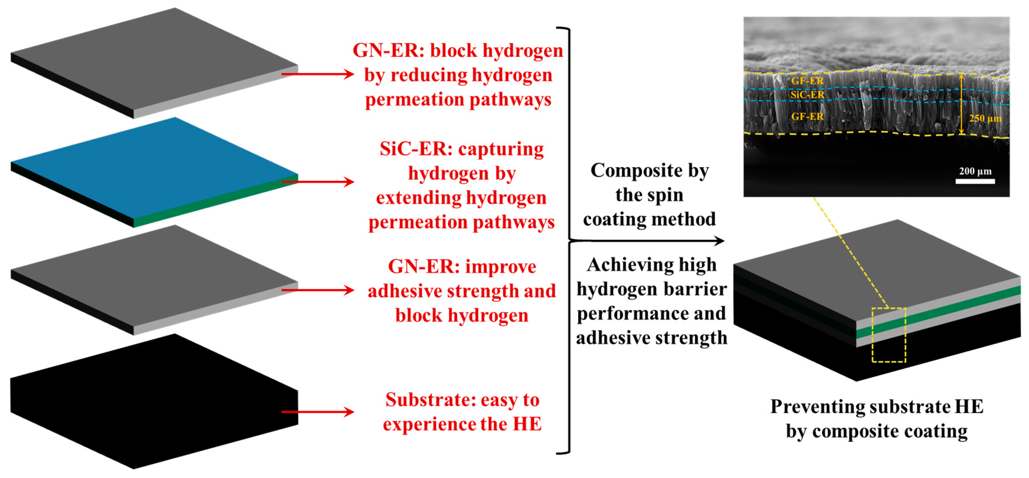
3. Results and Discussion

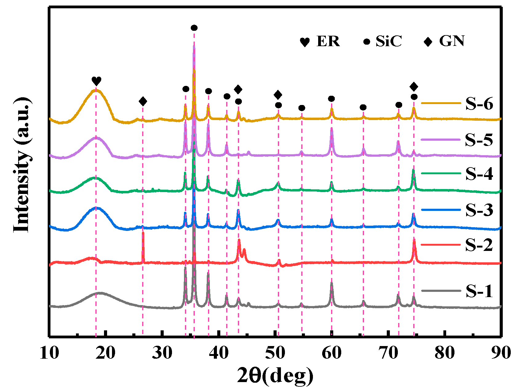
3.1. XRD Diffraction Analysis of the Coatings

Figure 2 displays the XRD from S-1 to S-6. All the samples exhibit relatively broad diffraction peak near the diffraction angle of 18°~19°, with a relatively high intensity, corresponding to the ER diffraction peak, indicating that the phase compositions of the coatings are ER-based [28,29]. The XRD diffraction peaks of the S-1 show the relatively sharp diffraction peaks at 34°, 36°, 38°, 60°, 72°, and 74°, corresponding to the PDF card numbered 29-1130. These diffraction peaks correspond to the XRD characteristic peaks of SiC [30,31,32,33,34]. The XRD diffraction peaks at 36°, 60° and 74° correspond to the (111), (220), and (311) crystal planes in the SiC crystal structure, respectively. Thus, the S-1 contains the SiC phase [30,31,32,33,34].
The XRD diffraction peaks from S-2 to S-6 display the diffraction peaks at 34°, 36°, 38°, 60°, 72°, and 74° (Figure 2), which are the same as S-1, corresponding to the PDF card numbered 29-1130, indicating that they all contain the SiC phase. For the S-2 to S-6, the XRD diffraction peaks appeared at the diffraction angles of 26°, 43°, 51° and 75° (Figure 2), which corresponded to the XRD characteristic peaks of the GN [30,35,36,37,38]. The XRD characteristic peaks at diffraction angles of 26° and 43° correspond to the (002) and (101) crystal planes of GN, respectively, indicating that S-2 to S-6 contain the GN [30,35,36,37,38]. From the diffraction angular displacements of S-2 to S-6, no angular shift was observed, displaying that the samples are composite structures rather than the solid solution [39,40,41,42,43]. This is because if the material is a composite structure, each component maintains the independent crystal structure, and its XRD pattern shows the superposition of different phase characteristic peaks, with each peak position consistent with the pure phase standard card, without systematic shift [39,40,41,42,43]. When the material forms the displacement or interstitial solid solution, solute atoms can cause the change in the lattice constant of the main crystal phase, resulting in an overall shift in XRD diffraction peaks towards higher angles (lattice contraction) or lower angles (lattice expansion) [39,40,41,42,43]. Therefore, the XRD characterization results indicate that S-2 to S-6 are composite phases of the SiC, GN, and GN-SiC with the ER matrix, respectively.
From Figure 2, comparing the relative intensities of XRD diffraction peaks at diffraction angles of 26°, 43°, 51° and 75°, the relative intensity of these diffraction angles of S-6 is higher than that of S-5, indicating that the relative content of GN in S-6 is greater than that in S-5. Comparing the relative intensities of XRD diffraction peaks at diffraction angles of 34°, 36°, 38°, 60° and 72°, the relative intensity of these diffraction angles of S-6 is lower than that of S-5, indicating that the relative content of SiC in S-6 is lower than that of S-5. These are consistent with the compositions of the sandwich composite coatings design. Similarly, comparing the relative intensities of XRD characteristic peaks of GN and SiC, the relative intensities of diffraction peaks of S-3 and S-4 are comparable, showing that the relative contents of GN and SiC in S-3 and S-4 are equivalent. That is consistent with the compositions of the design; only the coating composite sequence is different.

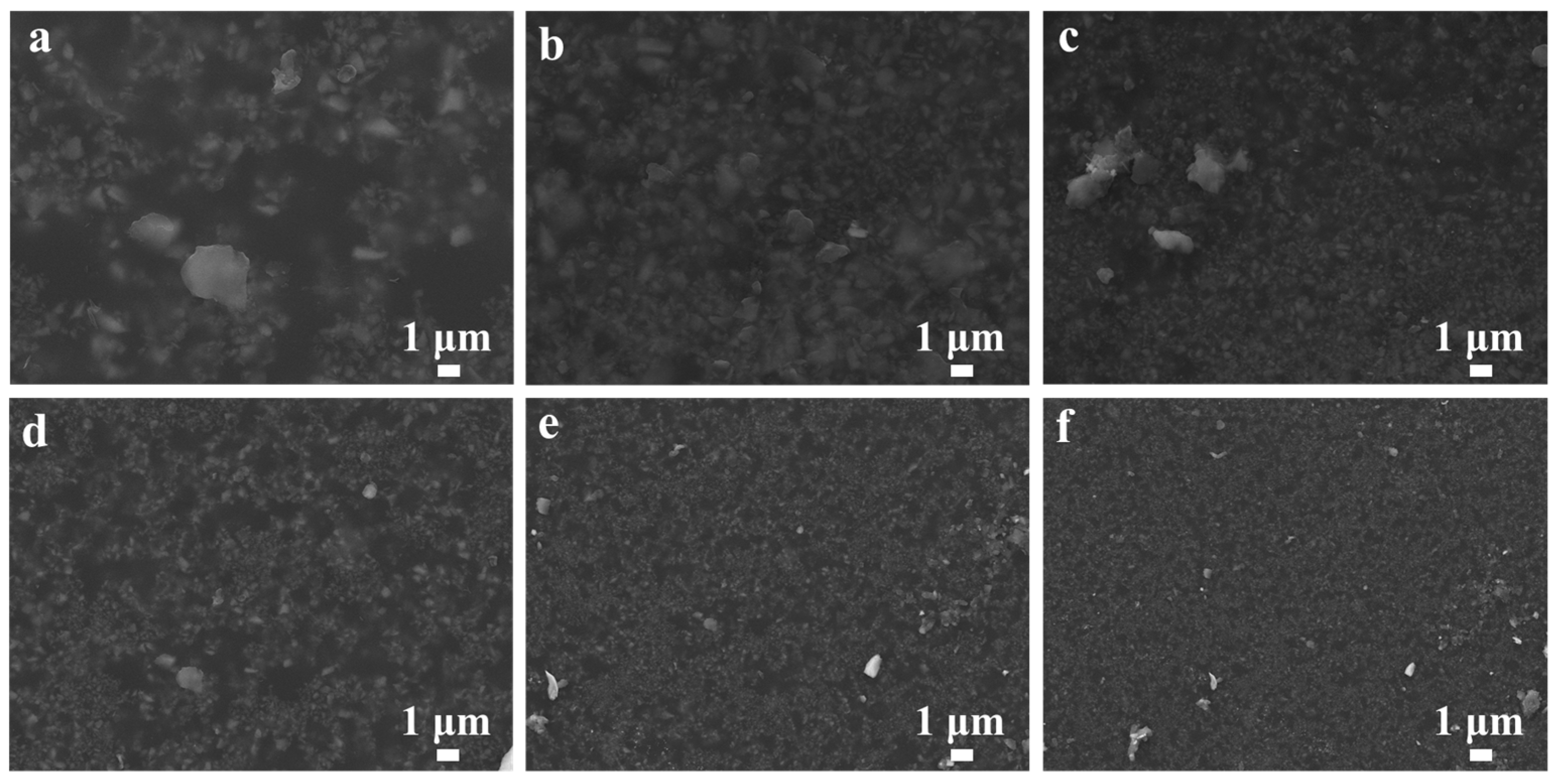
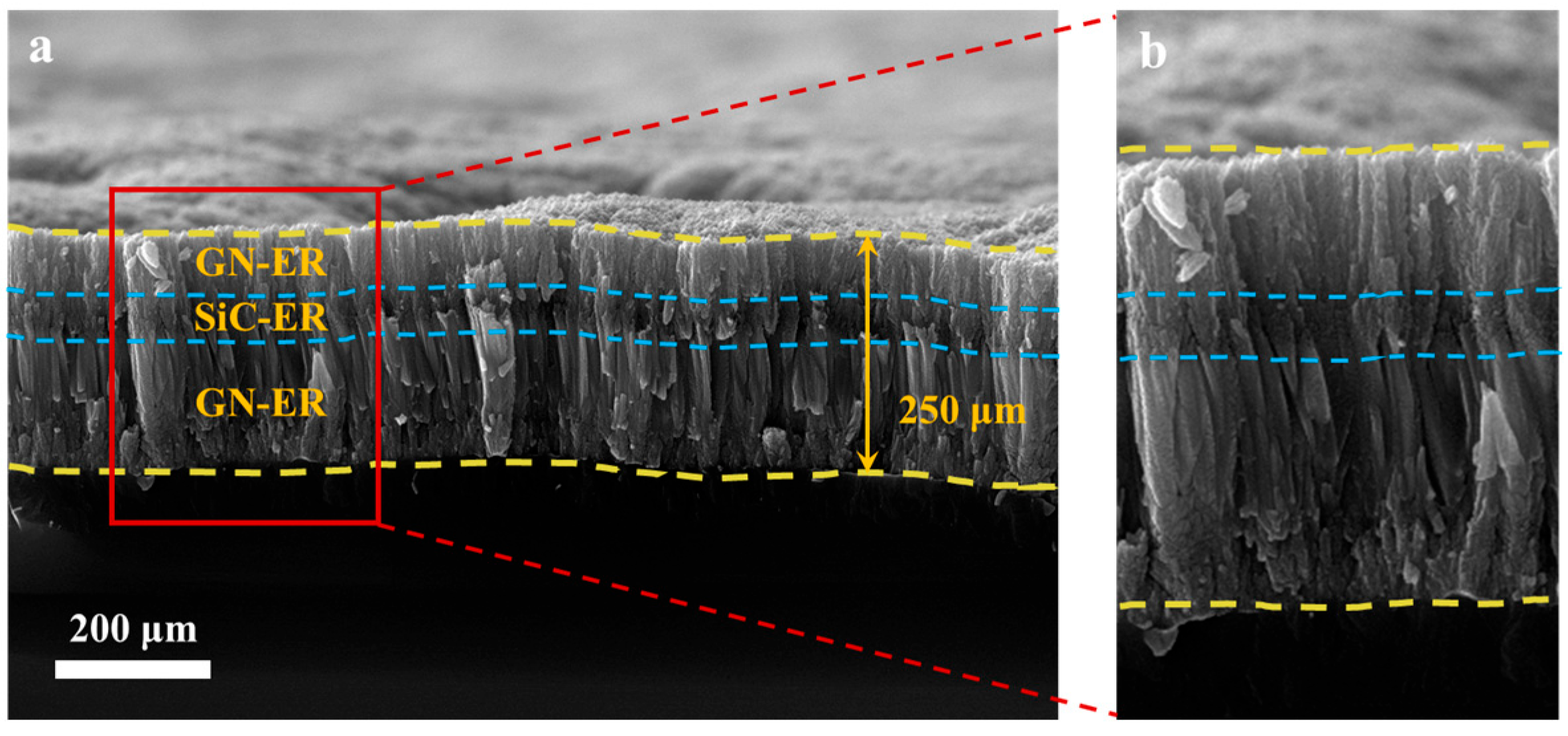
3.2. SEM Research on the Coatings

Figure 3 is the SEM of surfaces S-1 to S-6. Overall, all samples have uniform morphology and flatness, as well as high density. These factors can reduce the diffusion channels, help block the diffusion of H, and improve hydrogen barrier performances [11,12,13,18,19]. Compared to the single-layer coatings (S-1 and S-2), the double-layer coatings (S-3 and S-4) and the three-layer coatings (S-5 and S-6) have smoother surfaces and higher densities. This may be related to the fact that multiple spin coatings can improve surface properties. S-6 has the most uniform morphology and surface smoothness among all samples, and there are no pores in it, which is beneficial for obtaining relatively high hydrogen barrier performance.
Figure 4 displays the SEM of the S-6 cross-section. From Figure 4, it can be seen that there is a clear interface between the layers of S-6, and the thickness of the three layers is about 250 μm, indicating the sandwich structures. The first layer (the innermost layer) of GN-ER is relatively thick, with a thickness of approximately 130 μm, while the second layer (the middle layer) of SiC-ER and the third layer (the outermost layer) of GN-ER have a total thickness of approximately 120 μm (Figure 4b). The thickness of the second layer is slightly smaller than that of the third layer. The more GN-ER is used to effectively prevent the diffusion of H. Moreover, there are no pores and defects at the interface between the layers of S-6, which can help to enhance the adhesive strength [44,45]. This design can reduce the channels for H diffusion at the interface between layers, providing the basis for the middle layer to absorb the H diffused from the outermost layer, which is beneficial for improving the hydrogen barrier performances of the composite coatings [22,23,24,25,26,27].

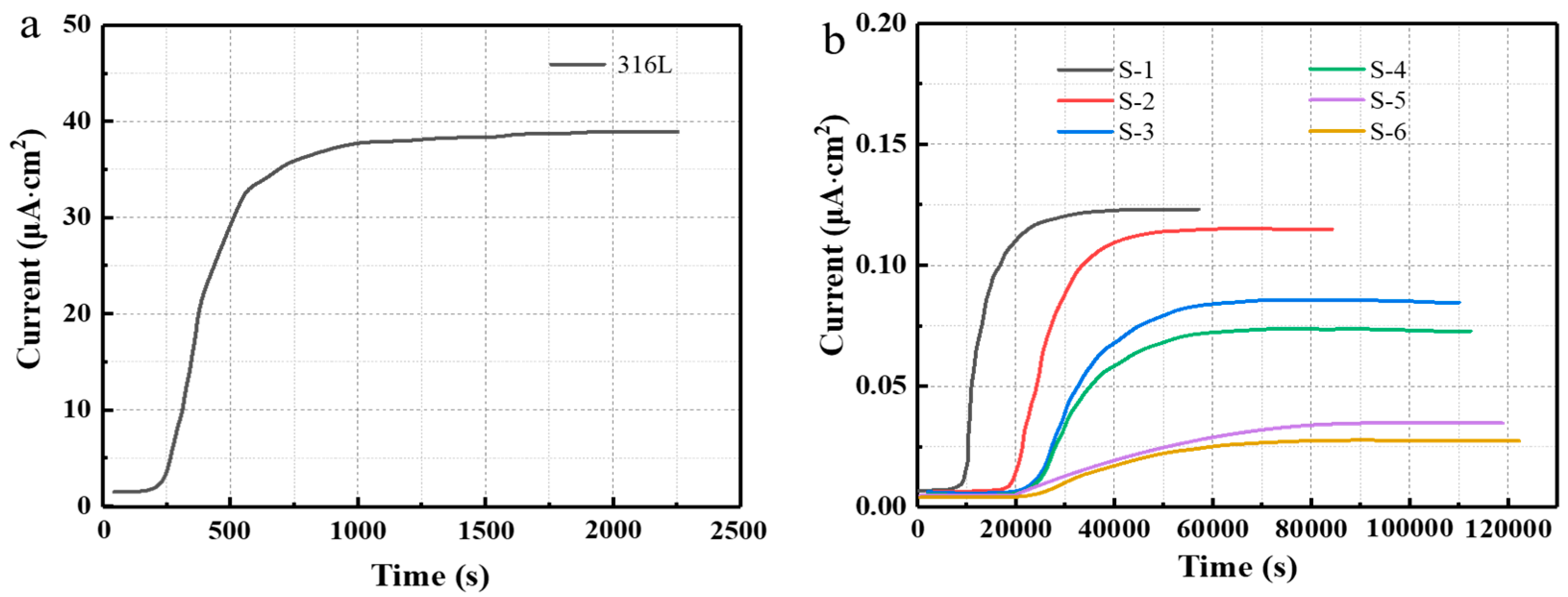
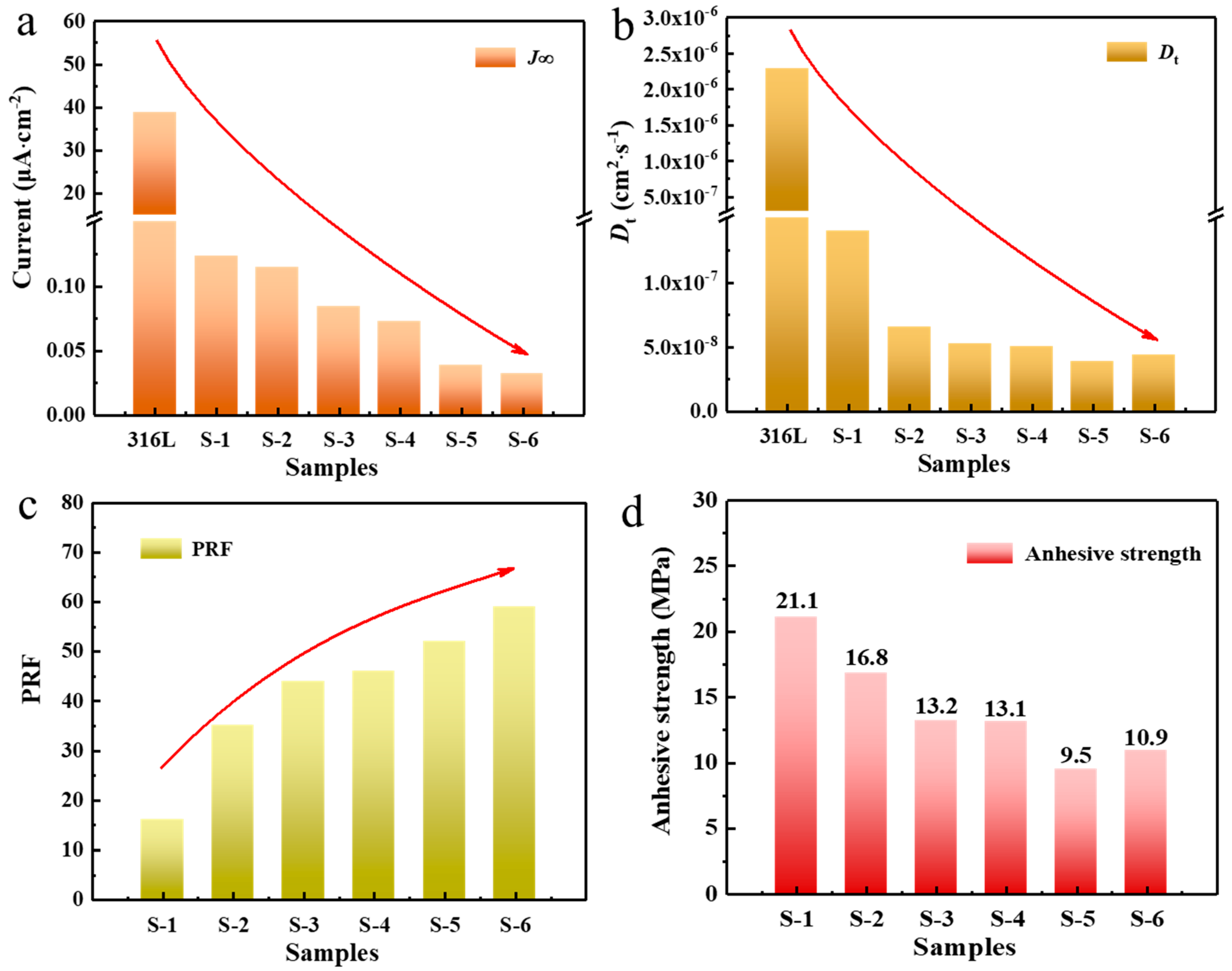
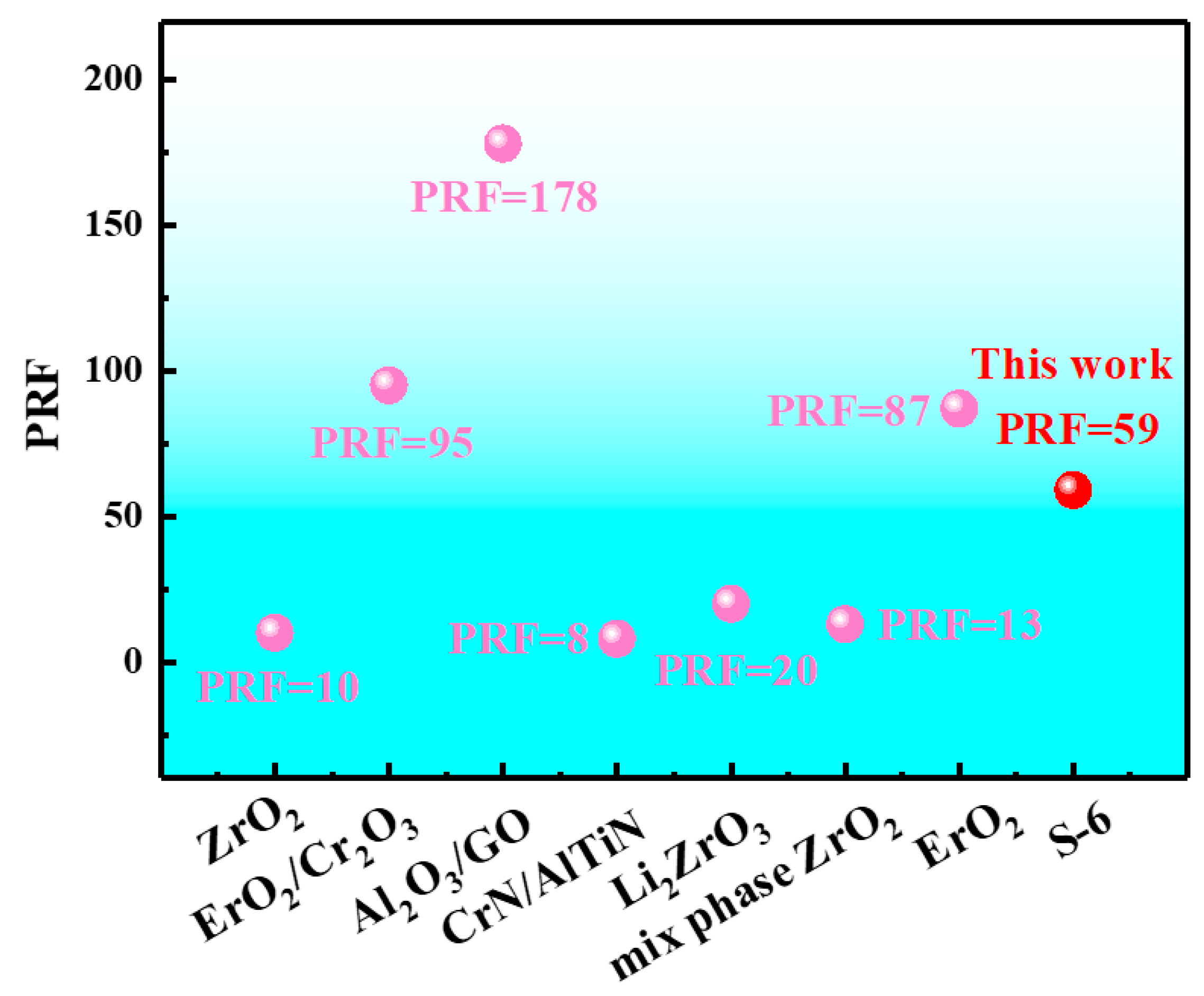
3.3. Hydrogen Barrier Performances of the Coatings

Figure 5 shows the electrochemical hydrogen permeation curves of the substrate and the coatings. Table 2 shows the electrochemical hydrogen permeation parameters of the substrate and the coatings. The electrochemical hydrogen permeation curve of the substrate is shown in Figure 5a. From Figure 5a and Table 2, the current density of the substrate presents a steep trend with the extension of time, first rapidly increasing and then steadily approaching a straight line. The substrate reached J (38.893 μA·cm−2) at 2250 s, indicating the poor hydrogen barrier performance. Figure 5b shows the electrochemical hydrogen permeation curves of the S-1 to S-6. From Table 2 and Figure 5b, the current density of S-1 and S-2 exhibits a trend of rapid increase followed by a stable trend towards a straight line with the extension of time, similar to the curve shape of S-1. The steep shapes of the electrochemical hydrogen permeation curves of the S-3 and S-4 become gentler. The current density of S-5 and S-6 displays an increasing trend followed by a gradual decrease over time. All the samples reached J for more than 58,000 s, which was greater than that of 2250 s of S-1, and J was less than 0.125 μA·cm−2, which was far less than that of S-1 with a value of 38.893 μA·cm−2. Generally, the longer the hydrogen permeation time is and the lower the J is, the less the hydrogen permeation is and the better the hydrogen barrier performance is. The results indicate that the hydrogen barrier performance of S-1 to S-6 has been significantly improved compared to the substrate.
Figure 6a shows the trend of J changes for the substrate and S-1 to S-6. From Figure 5b and Figure 6a, the saturation current time of the substrate and S-1 to S-6 continue to increase, and J continues to decrease, indicating that the ability to block hydrogen penetration of the coatings is constantly strengthening in order to improve the hydrogen barrier performance of coatings. The order of J from top to bottom is substrate > S-1 > S-2 > S-3 > S-4 > S-5 > S-6. This is because the multi-layer composite coatings can effectively reduce the diffusion channels of hydrogen and improve the hydrogen barrier [11,12,13,18,19,46]. When the coatings are three-layered, they have a better hydrogen barrier effect compared to that of the double-layered. Specifically, S-6 exhibited the longest saturation current time (122,000 s) and the lowest J (μA·cm−2) among all the samples, exhibiting the best hydrogen barrier performance.
According to Formulas (1) and (2), the specific values of Dt-substrate, Dt-coatings, and PRF can be calculated as shown in Table 2. Figure 6b,c shows the trend of the Dt and the PRF changes with the coating types, respectively. From Figure 6b,c, as the coating progresses from a single layer to multiple layers, the values of Dt and PRF show a continuous decreasing and increasing trend, respectively. The smaller the values of Dt and the larger the values of PRF are, the better the hydrogen barrier performances of the coatings are. The results indicate that compared to a single layer, the hydrogen barrier performances of the multi-layer coatings (the S-3 to S-6) have significant advantages. Additionally, the hydrogen barrier performances of the three layers (the S-5 and S-6) are superior to that of the double layers (the S-3 and S-4), which may be related to the fact that the three layers have the innermost hydrogen-blocking effect [20,21,22].
S-6 shows a lower value of Dt and a higher value of PRF than those of S-5 (Figure 6b,c), indicating better hydrogen barrier performance. The difference between S-6 and S-5 lies in the stacking ways of the three-layered structures, that is, S-6 with (GN-ER)/(SiC-ER)/(GN-ER) and S-5 with (SiC-ER)/(GN-ER)/(SiC-ER), which results in differences in hydrogen barrier performance. S-6 exhibits superior hydrogen barrier performance that may be attributed to the hydrogen permeation energy barrier and the hydrogen permeation channels [20,21,22,23]. In terms of the hydrogen permeation energy barrier, GN has stable physical and chemical properties, and its dense network electron cloud distribution has a strong blocking effect on hydrogen. The adsorption of H into GN requires overcoming the energy barrier of 4.61 eV, which is greater than the 1.4 eV barrier in common coatings [20,21,22,23]. In terms of the hydrogen permeation channels, the sheet-like structures of GN are uniformly dispersed in the ER, resulting in an increase in curvature. The gas molecules are forced to follow the complex and tortuous routes through the impenetrable filler flakes, leading to a significant increase in the time required for gas molecules to pass through the composite coatings (Figure 5b), thereby reducing the breathability of the composite coatings. When the hydrogen attempts to pass through the ER, it may physically entangle within the GN structures. This mechanical interception can further delay the free movement of hydrogen, resulting in a decrease in permeability [20,21,22,23]. Another possible reason for the difference in hydrogen barrier performance between S-6 and S-5 is that S-6 has higher adhesive strength (10.9 MPa) than S-5 (9.5 MPa), which is shown in Figure 6d. This may be because using SiC-ER as the innermost layer can reduce the adhesive strength of the composite coatings [47,48]. Figure 6d exhibits the trend of the adhesive strength as the layers increase. Blindly increasing the layers will reduce the adhesive strength and may not be conducive to enhancing the hydrogen barrier performance. Therefore, the three-layered coatings show good performance, and the stacking ways need to be adjusted.
We compared the hydrogen barrier performances of previous studies on the inorganic single-layered coatings and the inorganic composite coatings through PRF values, which are shown in Figure 7 [49,50,51,52,53,54,55]. The PRF values of the single-layered oxide coatings are relatively low, such as ZrO2 (10) and Li2ZrO3 (20) [49,53]. The composite coatings present higher PRF values than those of the single-layered oxide coatings, such as ErO2/Cr2O3 (95) and Al2O3/GO (178) [50,51]. Because the composite structures can effectively solve the problems and defects of single-layered coatings and optimize the coating structures, the hydrogen barrier performances can be improved. Moreover, there is a large number of hydrogen traps at the interface between the coatings in the composite structures, which can capture the hydrogen, suppress the diffusion in the coatings and reduce the hydrogen permeability in order to enhance the hydrogen barrier performances. By comparison, the hydrogen barrier performances of the single-layered coatings need further improvement, which restricts their application. The composite coatings have relatively high hydrogen barrier performance and are expected to become the new generation of high-performance hydrogen barrier materials. The PRF value of S-6 in this work reached 59, which can provide ideas for designing organic composite coatings with high hydrogen barrier performance.

4. Conclusions

In this paper, we used the spin coating method to prepare the sandwich-structured (GN-ER)/(SiC-ER)/(GN-ER) coatings and compared the effects of the different composite methods on the hydrogen barrier performances of the coatings, including three-layer stacking sequences (S-5 and S-6), double-layer coatings (S-3 and S-4), and single-layer coatings (S-1 and S-2). The main conclusions are as follows:
Firstly, compared to the 316L substrate, the hydrogen barrier performances of the obtained coatings have been significantly improved, corresponding to PRF values between 16 and 59.
Secondly, the hydrogen barrier performance of the S-6 coatings are superior to the others (S-1 to S-5), including Dt (3.88 × 10⁻⁸ cm2·s−1) and PRF (59).
Thirdly, the composite coatings can improve the hydrogen barrier performance, which, by utilizing the hydrogen barrier–hydrogen storage–hydrogen barrier sandwich structure design, can be expected to provide ideas for designing the new hydrogen barrier coatings.
In summary, this research may provide a theoretical basis for improving the hydrogen barrier performance of coatings. Moreover, the S-6 coatings can be expected to be applied to prevent the HE in the pipelines and containers in order to ensure the safety of hydrogen energy storage and transportation.

Author Contributions

K.C. is responsible for the overall work, data analysis, and manuscript writing of this study. B.J. is responsible for the review and proofreading of the manuscript. All authors have read and agreed to the published version of the manuscript.

Funding

This research received no external funding.

Institutional Review Board Statement

Not applicable.

Informed Consent Statement

Not applicable.

Data Availability Statement

Data will be made available on reasonable request.

Conflicts of Interest

There are no conflicts to declare.

References

  1. Li, X.F.; Yin, J.; Zhang, J.; Wang, Y.F.; Song, X.L.; Zhang, Y.; Ren, X.C. Hydrogen embrittlement and failure mechanisms of multi-principal element alloys: A review. J. Mater. Sci. Technol. 2022, 122, 20–32. [Google Scholar] [CrossRef]
  2. Meda, U.S.; Bhat, N.; Pandey, A.; Subramanya, K.N.; Lourdu Antony Raj, M.A. Challenges associated with hydrogen storage systems due to the hydrogen embrittlement of high strength steels. Int. J. Hydrogen Energy 2023, 48, 17894–17913. [Google Scholar] [CrossRef]
  3. Kim, T.; Lee, J.; Kim, S.; Hong, E.; Lee, H. Hydrogen permeation barrier of carbon-doped TiZrN coatings by laser carburization. Corros. Sci. 2021, 19, 109700. [Google Scholar] [CrossRef]
  4. Bull, S.K.; Champ, T.A.; Raj, S.V.; O’Brien, R.C.; Musgrave, C.B.; Weimer, A.W. Atomic layer deposited boron nitride nanoscale films act as high temperature hydrogen barriers. Appl. Surf. Sci. 2021, 565, 150428. [Google Scholar] [CrossRef]
  5. Dehghanian, H.A.; Hosseinabadi, N. The hydrogen storage capacity of Al-Cu alloy with permeable alumina hydrogen permeation barrier (HPB) applied by plasma electrolytic oxidation (PEO). Int. J. Hydrogen Energy 2022, 47, 7339–7350. [Google Scholar] [CrossRef]
  6. Li, Z.L.; Yan, S.F.; Chen, W.D.; Zhang, Z.H.; Kang, Y.X.; Ma, W. The effect of current density on the anodic oxidation hydrogen barrier film on ZrH1.8 surface. Corros. Sci. 2024, 227, 111740. [Google Scholar] [CrossRef]
  7. Zhou, C.L.; Huang, Y.L.; Liu, X.H.; Huang, Y.; Wu, H.; Hua, Z.L.; Chu, P.K.; Yin, Y.S. Functionalized graphite nanosheet/organosilicon composite coatings with soft-hard structures: Excellent wear resistance and hydrogen barrier properties. Surf. Coat. Technol. 2025, 496, 131684. [Google Scholar] [CrossRef]
  8. Cho, J.; Kim, B.; Venkateshalu, S.; Chung, D.Y.; Lee, K.; Choi, S. Electrochemically activatable liquid organic hydrogen carriers and their applications. J. Am. Chem. Soc. 2023, 145, 16951–16965. [Google Scholar] [CrossRef]
  9. Lebedeva, O.; Kultin, D.; Каlenchuk, A.; Кustov, L. Advances and prospects in electrocatalytic hydrogenation of aromatic hydrocarbons for synthesis of “loaded” liquid organic hydrogen carriers. Curr. Opin. Electrochem. 2023, 38, 101207. [Google Scholar] [CrossRef]
  10. Rullo, F.; Beier, C.K.; Henseler, J.; Bösmann, A.; Preuster, P.; Wasserscheid, P.; Geißelbrecht, M. Pushing activity and stability of LOHC dehydrogenation catalysts by strict LOHC quality protocols. Int. J. Hydrogen Energy 2025, 98, 606–613. [Google Scholar] [CrossRef]
  11. Wu, M.; Chen, Y.; Peng, J.Q.; Yan, G.Q.; Sun, Y.P.; Zhang, J.D.; Zhang, S.L.; Wang, L.J. Hydrogen permeation resistance and characterization of Si-Al and Si-Zr composite sol oxide coating on surface of zirconium hydride. Rare Met. 2017, 36, 55–60. [Google Scholar] [CrossRef]
  12. Li, P.; Chen, K.; Zhao, L.L.; Zhang, H.Y.; Sun, H.X.; Yang, X.J.; Kim, N.H.; Lee, J.H.; Niu, Q.J. Preparation of modified graphene oxide/polyethyleneimine film with enhanced hydrogen barrier properties by reactive layer-by-layer self-assembly. Compos. Part B-Eng. 2019, 166, 663–672. [Google Scholar] [CrossRef]
  13. Huang, J.; Xie, H.; Luo, L.M.; Zan, X.; Liu, D.G.; Wu, Y.C. Preparation and properties of FeAl/Al2O3 composite tritium permeation barrier coating on surface of 316L stainless steel. Surf. Coat. Technol. 2020, 383, 125282. [Google Scholar] [CrossRef]
  14. Wang, F.Y.; Wang, J.; Lu, W.; Li, W.G.; Chu, D.L.; Wang, W.H. Multi-layer structured AlN/Er2O3 coating: Enhanced thermal stability and hydrogen isotope permeation resistance. Ceram. Int. 2024, 50, 40902–40910. [Google Scholar] [CrossRef]
  15. Liu, J.G.; Bi, H.S.; Zhang, Q.S.; Liu, S.Q.; Li, H.W.; Cui, G. Design, fabrication, and hydrogen blocking performance of alumina/zirconia functional gradient coatings. Ceram. Int. 2024, 50, 40902–40910. [Google Scholar] [CrossRef]
  16. Wan, H.X.; Cheng, Z.L.; Song, D.D.; Chen, C.F. Preparation and performance study of waterborne epoxy resin/non-covalent modified graphene oxide hydrogen barrier coatings. Int. J. Hydrogen Energy 2024, 53, 218–228. [Google Scholar] [CrossRef]
  17. Yuan, S.C.; Zhang, S.; Wei, J.T.; Gao, Y.; Zhu, Y.J.; Wang, H.Y. Materials selection, design, and regulation of polymer-based hydrogen barrier composite coatings, membranes and films for effective hydrogen storage and transportation: A comprehensive review. Int. J. Hydrogen Energy 2024, 91, 555–573. [Google Scholar] [CrossRef]
  18. Seo, O.B.; Saha, S.; Kim, N.H.; Lee, J.H. Preparation of functionalized mxene-stitched-graphene oxide/poly (ethylene-co-acrylic acid) nanocomposite with enhanced hydrogen gas barrier properties. J. Membrane. Sci. 2021, 640, 119839. [Google Scholar] [CrossRef]
  19. Saha, S.; Son, W.S.; Kim, N.H.; Lee., J.H. Fabrication of impermeable dense architecture containing covalently stitched graphene oxide/boron nitride hybrid nanofiller reinforced semi-interpenetrating network for hydrogen gas barrier applications. J. Mater. Chem. A 2022, 10, 4376–4391. [Google Scholar] [CrossRef]
  20. Nam, T.H.; Lee, J.H.; Choi, S.R.; Yoo, J.B.; Kim, J.G. Graphene coating as a protective barrier against hydrogen embrittlement. Int. J. Hydrogen Energy 2014, 39, 11810–11817. [Google Scholar] [CrossRef]
  21. Fan, Y.J.; Huang, Y.F.; Cui, B.; Zhou, Q. Graphene coating on nickel as effective barriers against hydrogen embrittlement. Surf. Coat. Technol. 2019, 374, 610–616. [Google Scholar] [CrossRef]
  22. Zhao, L.L.; Zhang, H.Y.; Kim, N.H.; Hui, D.; Lee, J.H.; Li, Q.; Sun, H.X.; Li, P. Preparation of graphene oxide/polyethyleneimine layer-by-layer assembled film for enhanced hydrogen barrier property. Compos. Part B-Eng. 2016, 92, 252–258. [Google Scholar] [CrossRef]
  23. Bandyopadhyay, P.; Park, W.B.; Layek, R.K.; Uddin, M.E.; Kim, N.H.; Kim, H.G.; Lee, J.H. Hexylamine functionalized reduced graphene oxide/polyurethane nanocomposite-coated nylon for enhanced hydrogen gas barrier film. J. Membr. Sci. 2016, 500, 106–114. [Google Scholar] [CrossRef]
  24. Liu, H.Y.; Bandyopadhyay, P.; Kshetri, T.; Kim, N.H.; Ku, B.C.; Moon, B.; Lee, J.H. Layer-by-layer assembled polyelectrolyte-decorated graphene multilayer film for hydrogen gas barrier application. Compos. Part B-Eng. 2017, 114, 339–347. [Google Scholar] [CrossRef]
  25. Alkrunz, M.; Shajahan, S.; Elkaffas, R.; Schiffer, A.; Zheng, L.X.; Liao, K.; Khan, M.Y.; Anjum, D.; Zweiri, Y.; Samad, Y.A. Fabrication and characterization of rippled graphene/LDPE composites with enhanced hydrogen barrier properties. Int. J. Hydrogen Energy 2024, 85, 794–803. [Google Scholar] [CrossRef]
  26. Liu, M.F.; Lin, K.L.; Zhou, M.Y.; Wallwork, A.; Bissett, M.A.; Young, R.J.; Kinloch, I.A. Mechanism of gas barrier improvement of graphene/polypropylene nanocomposites for new-generation light-weight hydrogen storage. Compos. Sci. Technol. 2024, 249, 110483. [Google Scholar] [CrossRef]
  27. Wan, H.X.; Song, X.X.; Cheng, Z.L.; Min, W.L.; Song, D.D.; Chen, C.F. Construction and properties of graphene oxide hydrogen-blocking coatings. Int. J. Hydrogen Energy 2024, 84, 410–419. [Google Scholar] [CrossRef]
  28. Longhi, M.; Zini, L.P.; Kunst, S.R.; Zattera, A.J. Influence of the type of epoxy resin and concentration of glycidylisobutyl-poss in the properties of nanocomposites. Polym. Polym. Compos. 2017, 25, 593–602. [Google Scholar] [CrossRef]
  29. Joseph, E.J.; Panneerselvam, K. Manufacturing and characterization of tungsten particulate-reinforced aw106 epoxy resin composites. Trans. Indian Inst. Met. 2021, 74, 817–825. [Google Scholar] [CrossRef]
  30. Sujith, R.; Chauhan, P.K.; Gangadhar, J.; Maheshwari, A. Graphene nanoplatelets as nanofillers in mesoporous silicon oxycarbide polymer derived ceramics. Sci. Rep. 2018, 8, 17633. [Google Scholar] [CrossRef]
  31. Wei, S.N.; Guan, L.; Song, B.Z.; Fan, B.B.; Zhao, B.; Zhang, R. Seeds-induced synthesis of SiC by microwave heating. Ceram. Int. 2019, 45, 9771–9775. [Google Scholar] [CrossRef]
  32. Yang, H.Y.; Li, M.Y.; Zhou, X.G.; Wang, H.L.; Yu, J.S. Flexural modulus of SiC/SiC composites sintered by microwave and conventional heating. Ceram. Int. 2019, 45, 10142–10148. [Google Scholar] [CrossRef]
  33. Li, B.B.; Mao, B.X.; Wang, X.B.; He, T. Fabrication and frictional wear property of bamboo-like SiC nanowires reinforced SiC coating. Surf. Coat. Technol. 2019, 45, 10142–10148. [Google Scholar] [CrossRef]
  34. Lü, X.X.; Li, L.B.; Sun, J.J.; Yang, J.H.; Jiao, J. Microstructure and tensile behavior of (BN/SiC)n coated SiC fibers and SiC/SiC minicomposites. J. Eur. Ceram. Soc. 2023, 43, 1828–1842. [Google Scholar] [CrossRef]
  35. Stobinski, L.; Lesiak, B.; Malolepszy, A.; Mazurkiewicz, M.; Mierzwa, B.; Zemek, J.; Jiricek, P.; Bieloshapka, I. Graphene oxide and reduced graphene oxide studied by the XRD, TEM and electron spectroscopy methods. J. Electron Spectrosc. 2014, 195, 145–154. [Google Scholar] [CrossRef]
  36. Hu, Z.R.; Tong, G.Q.; Lin, D.; Nian, Q.; Shao, J.Y.; Hu, Y.W.; Saeib, M.; Jin, S.Y.; Cheng, G.J. Laser sintered graphene nickel nanocomposites. J. Mater. Process. Technol. 2016, 231, 143–150. [Google Scholar] [CrossRef]
  37. Houshi, M.N.; Aakyiir, M.; Ma, J. Low-temperature, rapid preparation of functionalized graphene platelets. Compos. Commun. 2020, 22, 100500. [Google Scholar] [CrossRef]
  38. Chen, G.J.; Ng, K.Y.S.; Lin, C.C. Effects of nitrogen-doping or alumina films on graphene as anode materials of lithium-ion batteries verified by in situ XRD. J. Nanomater. 2022, 2022, 1758789. [Google Scholar] [CrossRef]
  39. Liu, J.C.; Su, Z.J.; Xu, J.M.; Zhang, Y.B. Thermal storage performance of NaNO3/cordierite-mullite ceramic (CMC) composites deriving from metallurgical slag. Ceram. Int. 2023, 49, 38094–38102. [Google Scholar] [CrossRef]
  40. Yang, W.T.; Zheng, G.P. The enhanced energy storage properties of (1-x)(0.94BNT-0.06BT)-x(Bi0.2Na0.2K0.2La0.2Sr0.2)TiO3 solid solutions. Ceram. Int. 2024, 50, 7834–7842. [Google Scholar] [CrossRef]
  41. Chen, Y.H.; Sun, J.X.; Chai, Z.H.; Zhang, B.Q.; Cao, Y.; Zhang, Y.H. High thermal conductivity and high energy density compatible latent heat thermal energy storage enabled by porous Al2O3@Graphite ceramics composites. Ceram. Int. 2024, 50, 19864–19872. [Google Scholar] [CrossRef]
  42. Dou, Z.M.; Yang, Y.; Zhou, L.; Luo, G.G.; Li, Y.H.; Hu, J.; Wang, S.X.; Wang, W.; Ruan, S.J.; Zhang, G.Z.; et al. Enhancing energy storage performance in multilayer ceramic capacitors with (Pb,La)(Zr,Sn,Ti)O3-based antiferroelectric solid solutions. Appl. Mater. Today 2024, 41, 102488. [Google Scholar] [CrossRef]
  43. Shen, Y.Q.; Xu, X.H.; Wu, J.F.; Yu, J.Q.; Qiu, S.X.; Zhang, D. Effect of ZrO2-MoO3 on the properties of in situ synthesized corundum-mullite composite thermal storage ceramics. Ceram. Int. 2025, 51, 6110–6124. [Google Scholar] [CrossRef]
  44. Chen, W.L.; Meng, X.N.; Wu, D.Q.; Yao, D.C.; Zhang, D.D. The effect of vacuum annealing on microstructure, adhesion strength and electrochemical behaviors of multilayered AlCrTiSiN coatings. Appl. Surf. Sci. 2019, 467–468, 391–401. [Google Scholar] [CrossRef]
  45. Warcaba, M.; Kowalski, K.; Kopia, A.; Moskalewicz, T. Impact of surface topography, chemistry and properties on the adhesion of sodium alginate coatings electrophoretically deposited on titanium biomaterials. Metall. Mater. Trans. A 2021, 52, 4454–4467. [Google Scholar] [CrossRef]
  46. Wan, H.X.; Min, W.L.; Song, D.D.; Chen, C.F. Research progress of hydrogen blocking coatings. Mater. Chem. Phys. 2024, 328, 130028. [Google Scholar] [CrossRef]
  47. Lv, J.; Zhu, C.X.; Qiu, H.N.; Zhang, J.; Gu, C.D.; Feng, J. Robust icephobic epoxy coating using maleic anhydride as a crosslinking agent. Prog. Org. Coat. 2020, 142, 105561. [Google Scholar] [CrossRef]
  48. Li, B.; Qian, S.; Sun, C.; Wang, M.; Zhan, X. Mechanical properties and wear resistance of Cf/epoxy resin composites with in-situ grown SiC nanowires on carbon fibers. Compos. Interface 2023, 30, 923–939. [Google Scholar] [CrossRef]
  49. Nakamura, H.; Isobe, K.; Nakamichi, M.; Yamanishi, T. Evaluation of deuterium permeation reduction factor of various coatings deposited on ferritic/martensitic steels for development of tritium permeation barrier. Fusion Eng. Des. 2010, 85, 1531–1536. [Google Scholar] [CrossRef]
  50. Wu, Y.Y.; Wang, S.M.; Li, S.; He, D.; Liu, X.P.; Jiang, L.J.; Huang, H.T. Deuterium permeation properties of Er2O3/Cr2O3 composite coating prepared by MOCVD on 316L stainless steel. Fusion Eng. Des. 2016, 113, 205–210. [Google Scholar] [CrossRef]
  51. Yang, H.; Shao, Z.M.; Wang, W.; Ji, X.; Li, C.J. A composite coating of GO-Al2O3 for tritium permeation barrier. Fusion Eng. Des. 2020, 156, 111689. [Google Scholar] [CrossRef]
  52. Hu, L.L.; Wei, G.; Yin, R.; Hong, M.Q.; Cheng, T.; Zhang, D.X.; Zhao, S.Q.; Yang, B.; Zhang, G.K.; Cai, G.X.; et al. Significant hydrogen isotopes permeation resistance via nitride nano-multilayer coating. Int. J. Hydrogen Energy 2020, 45, 19583–19589. [Google Scholar] [CrossRef]
  53. Mukai, K.; Kenjo, S.; Iwamatsu, N.; Mahmoud, B.; Chikada, T.; Yagi, J.; Konishi, S. Hydrogen permeation from F82H wall of ceramic breeder pebble bed: The effect of surface corrosion. Int. J. Hydrogen Energy 2022, 47, 6154–6163. [Google Scholar] [CrossRef]
  54. Wang, Z.G.; Chen, W.D.; Yan, S.F.; Zhong, X.K.; Ma, W.; Song, X.W.; Wang, Y.M.; Ouyang, J.H. Direct fabrication and characterization of zirconia thick coatings on zirconium hydride as a hydrogen permeation barrier. Coatings 2023, 13, 884. [Google Scholar] [CrossRef]
  55. Raia, S.; Rayjada, P.A.; Dhorajiya, P.B.; Patel, R.B.; Sharma, S.K.; Sircar, A.; Bhattacharyay, R. Deuterium permeation studies through bare and Er2O3 coated SS 316L. Fusion Eng. Des. 2024, 206, 114587. [Google Scholar] [CrossRef]
Figure 1. Schematic diagram of the (GN-ER)/(SiC-ER)/(GN-ER) sandwich structure composite hydrogen barrier coating.
Coatings 15 00518 g001
Figure 2. XRD of S-1 to S-6.
Coatings 15 00518 g002
Figure 3. SEM of surfaces S-1 to S-6: (a) S-1, (b) S-2, (c) S-3, (d) S-4, (e) S-5, (f) S-6.
Coatings 15 00518 g003
Figure 4. (a) SEM of the S-6 cross-section; (b) partially enlarged SEM of the S-6 cross-section (red rectangle). From the top to bottom, the interval corresponding to the first yellow dashed line and the first blue dashed line is the GN-ER. The interval corresponding to the first and second blue dashed lines is the SiC-ER. The interval corresponding to the second blue dashed line and the second yellow dashed line is the GN-ER.
Coatings 15 00518 g004
Figure 5. Electrochemical hydrogen permeation curves of the substrate (a) and the coatings (b).
Coatings 15 00518 g005
Figure 6. (a) Comparison of the saturation current of the samples. (b) Comparison of the electrochemical hydrogen diffusion coefficient of the samples. (c) Comparison of the PRF of the samples. (d) Adhesive strength of S-1 to S-6.
Coatings 15 00518 g006
Figure 7. Comparison of PRF between the reported coatings and S-6 [49,50,51,52,53,54,55]. The previous studies on the inorganic single-layered coatings and the inorganic composite coatings include the ZrO2 [49], ErO2/Cr2O3 [50], Al2O3/GO [51], CrN/AlTiN [52], Li2ZrO3 [53], mix phase ZrO2 [54], and ErO2 [55]. The GO means the graphene oxide [51].
Coatings 15 00518 g007
Table 1. Coating types and their numbers.
Serial NumbersCoating TypesNumbers of the Samples
1SiC-ERS-1
2GN-ERS-2
3(SiC-ER)/(GN-ER)S-3
4(GN-ER)/(SiC-ER)S-4
5(SiC-ER)/(GN-ER)/(SiC-ER)S-5
6(GN-ER)/(SiC-ER)/(GN-ER)S-6
Table 2. Electrochemical hydrogen permeation parameters of the substrate and the coatings.
Samplest0.632 (s)J (μA·cm−2)Dt (10−8 cm2·s−1)PRF
316L72938.893228.62/
S-111,9320.1231313.9716
S-225,5780.114916.5235
S-331,7180.0845875.2544
S-433,2640.0727455.0146
S-538,0150.0347404.3852
S-642,9870.0291003.8859
Disclaimer/Publisher’s Note: The statements, opinions and data contained in all publications are solely those of the individual author(s) and contributor(s) and not of MDPI and/or the editor(s). MDPI and/or the editor(s) disclaim responsibility for any injury to people or property resulting from any ideas, methods, instructions or products referred to in the content.

