

A Mechanism of Argon Arc Remelting of LPBF 18Ni300 Steel Surfaces


Abstract
1. Introduction
2. Materials and Methods
2.1. Materials
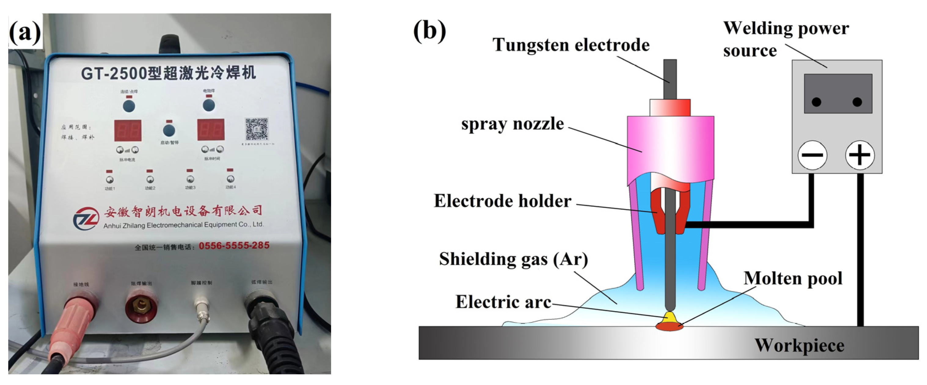
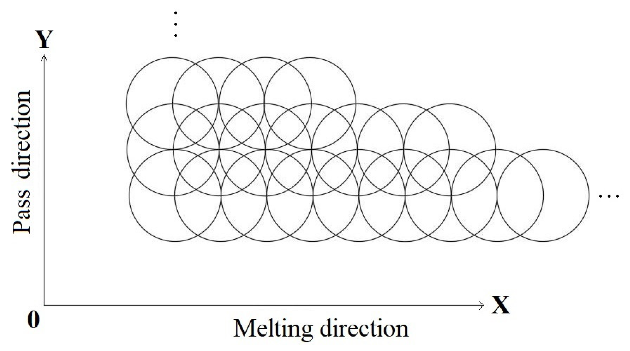
2.2. Argon Arc Remelting
2.3. Structural Observation and Performance Test
3. Results and Discussion
3.1. Macro-Morphology
3.2. Macrostructure
3.3. Grain Structure
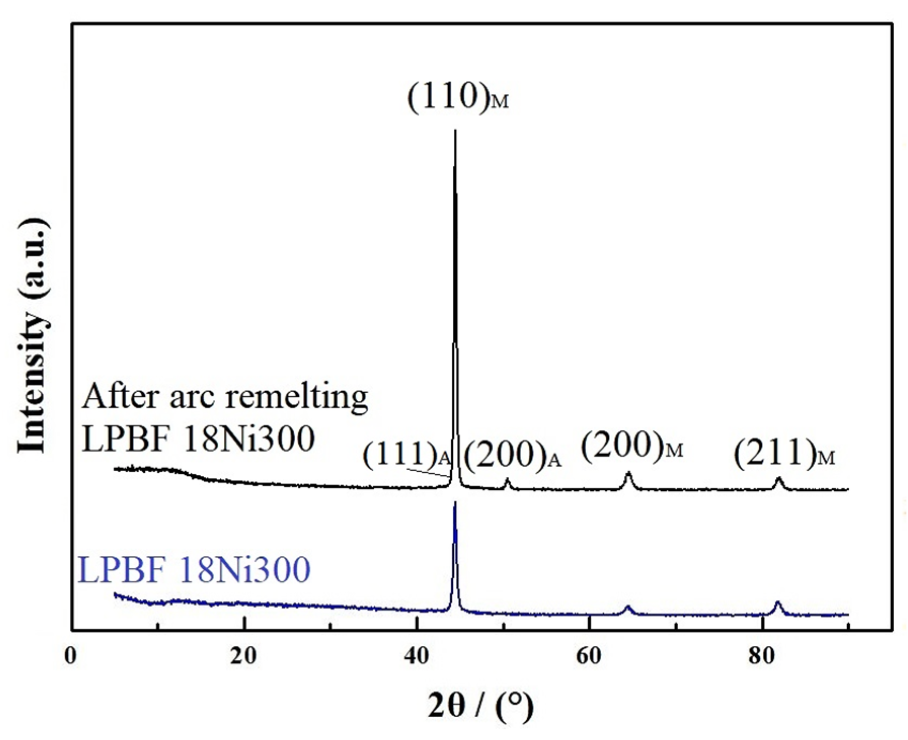
3.4. Physical Phase Analysis
3.5. Vicker’s Hardness
- (1)
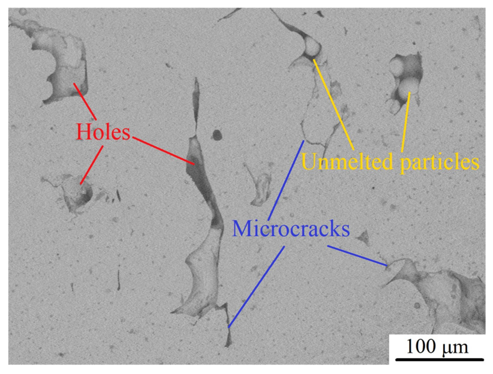
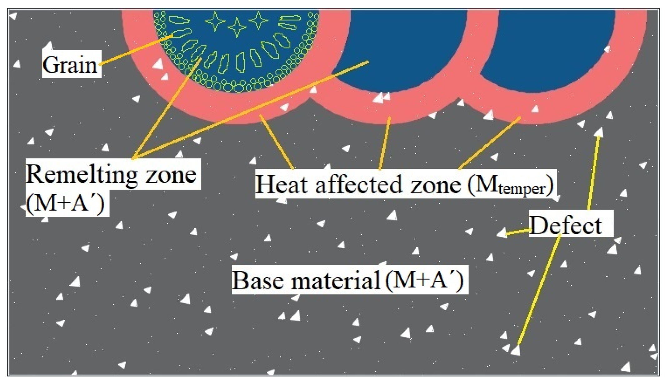
- Weakening of pores (defects). In general, the strength and porosity of materials can be expressed as [31,35]:where is the strength when the porosity is 0, is the porosity, and is a constant. As observed, there is an exponential function relationship between material strength and porosity, and the material strength may be greatly reduced with the increase in its porosity. After argon arc remelting, the defects, such as pores, microcracks, and unmelted metal particles in the remelted layer of LPBF 18Ni300, are significantly reduced (as shown in the blue part of Figure 16). When materials are subjected to a load, pore elimination may increase the cross-sectional area of the load on the one hand; and stress concentration is prone to occur near voids, avoiding the formation of crack sources and accordingly increasing material strength on the other hand. However, when the current increases to 22 A, the driving force in the molten pool increases, the convection becomes more intense, and larger pores and a few small shrinkage pores appear in the remelted layer, resulting in a significant decrease in hardness. Therefore, the weakening mechanism of pores (defects) is the primary factor affecting the hardness change of LPBF 18Ni300 after surface argon arc remelting.
- (2)
- Phase transition strengthening. As shown in Figure 13, the heat-affected zone is completely transformed into tempered martensite, which has high strength and hardness after the argon arc action. According to the mixing ratio principle [36,37], the strength of a material under load is as follows:where is material strength, is the phase strength of , is the phase volume fraction of , is the phase strength of , and is the phase volume fraction of . According to Table 2, as the current increases, the thickness of the heat-affected layer gradually increases (as shown in the red part of Figure 16), and the volume content of tempered martensite increases as well. Then, the hardness increases accordingly. Due to a small amount of tempered martensite, the phase transition strengthening mechanism plays a secondary role in the surface argon arc remelting of LPBF 18Ni300.
- (3)
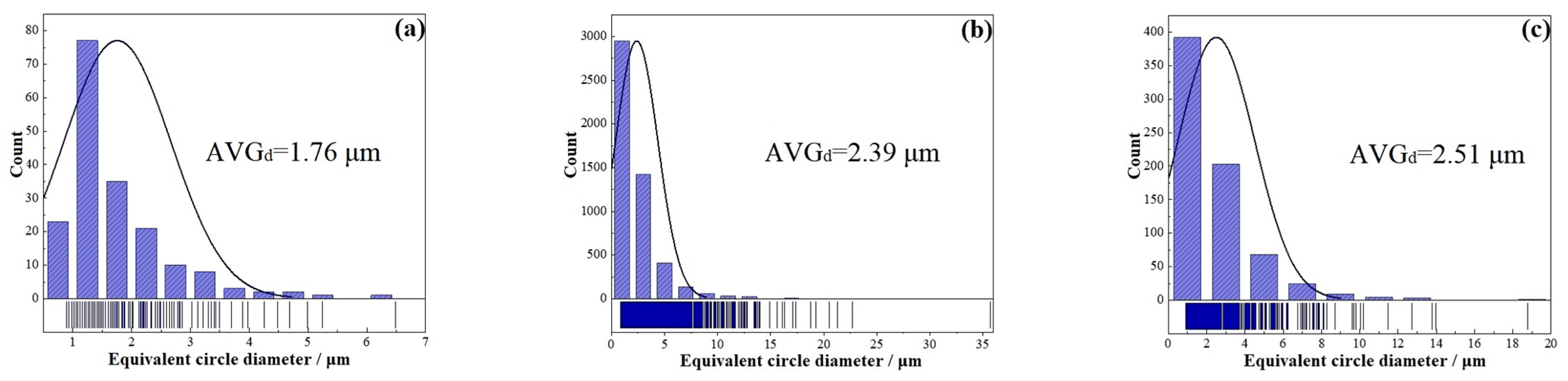
- Fine-grain strengthening. According to the Hall–Petch formula, the material strength and the grain size and content conform to the following relationship [38,39]:where is the yield strength, and are constants, and is the grain size. The smaller the grain diameter , the higher the yield strength. As shown in Figure 8 and Figure 15, the grain size gradually decreases and the hardness gradually increases from the center to the bottom of the molten pool, which conforms to the Hall–Petch formula. However, in Figure 11, average grain sizes of the base material, heat-affected zone, and remelted layer are approximately 1.76 μm, 2.39 μm and 2.51 μm, respectively. After the calculation, the grain sizes and hardness values of the base material, heat-affected zone, and remelted layer are not closely related to Formula (5), mainly due to the significant influence of the martensitic phase transition strengthening mechanism. Overall, the contribution of the fine-grain strengthening mechanism to the hardness of LPBF 18Ni300 after surface argon arc remelting is not as significant as the first two factors.
- (4)
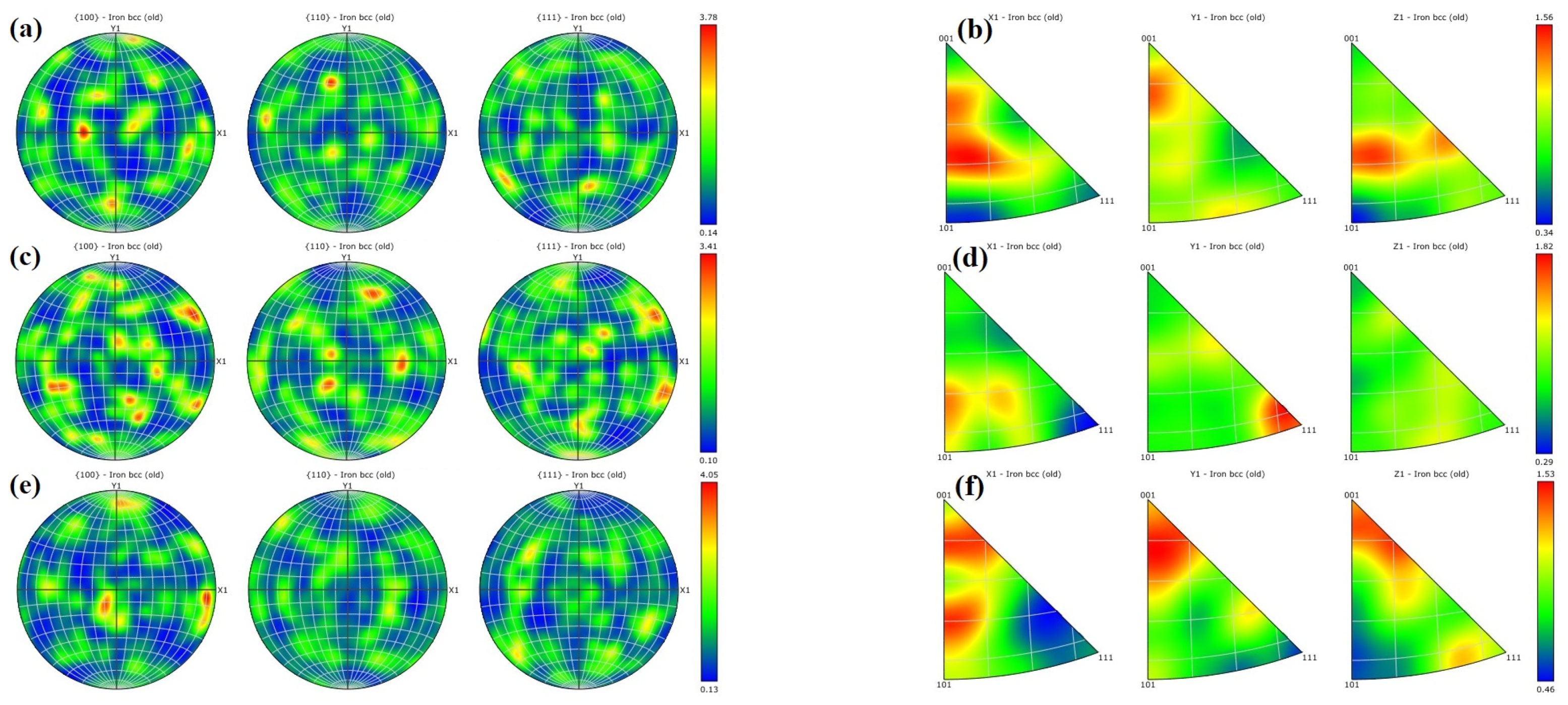
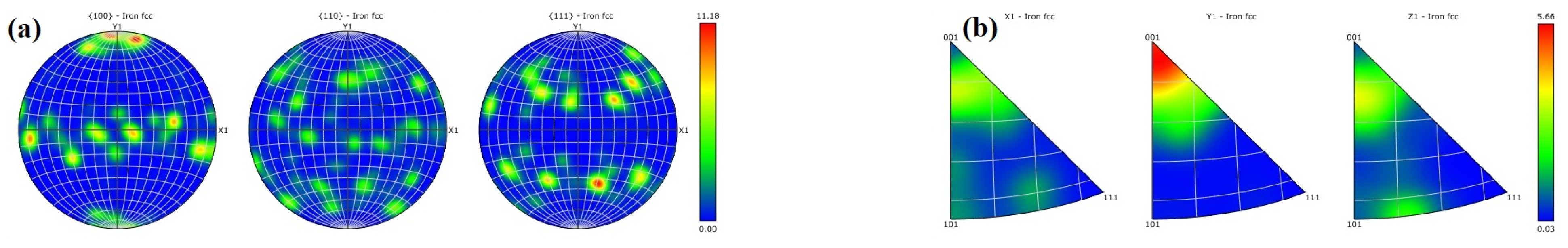
- Texture strengthening. The formula for texture strengthening can be expressed as [40,41]:where is the strength contributed by texture strengthening, is a constant and is the Schmidt factor. The strength contributed by texture strengthening is inversely proportional to the Schmidt factor . According to Figure 10, the martensite Schmid factor is 0.26 for the LPBF 18Ni300 sample base material after surface argon arc remelting, 0.29 for the heat-affected zone, and 0.24 for the remelted layer. The difference in Schmidt factor is not significant, and grains with the texture in the <001> direction are mostly distributed at the bottom of the molten pool. After the calculation according to Formula (6), the correlation between hardness change and texture strengthening is not significant. So, the contribution of the texture strengthening mechanism to hardness is very small.
4. Conclusions
- (1)
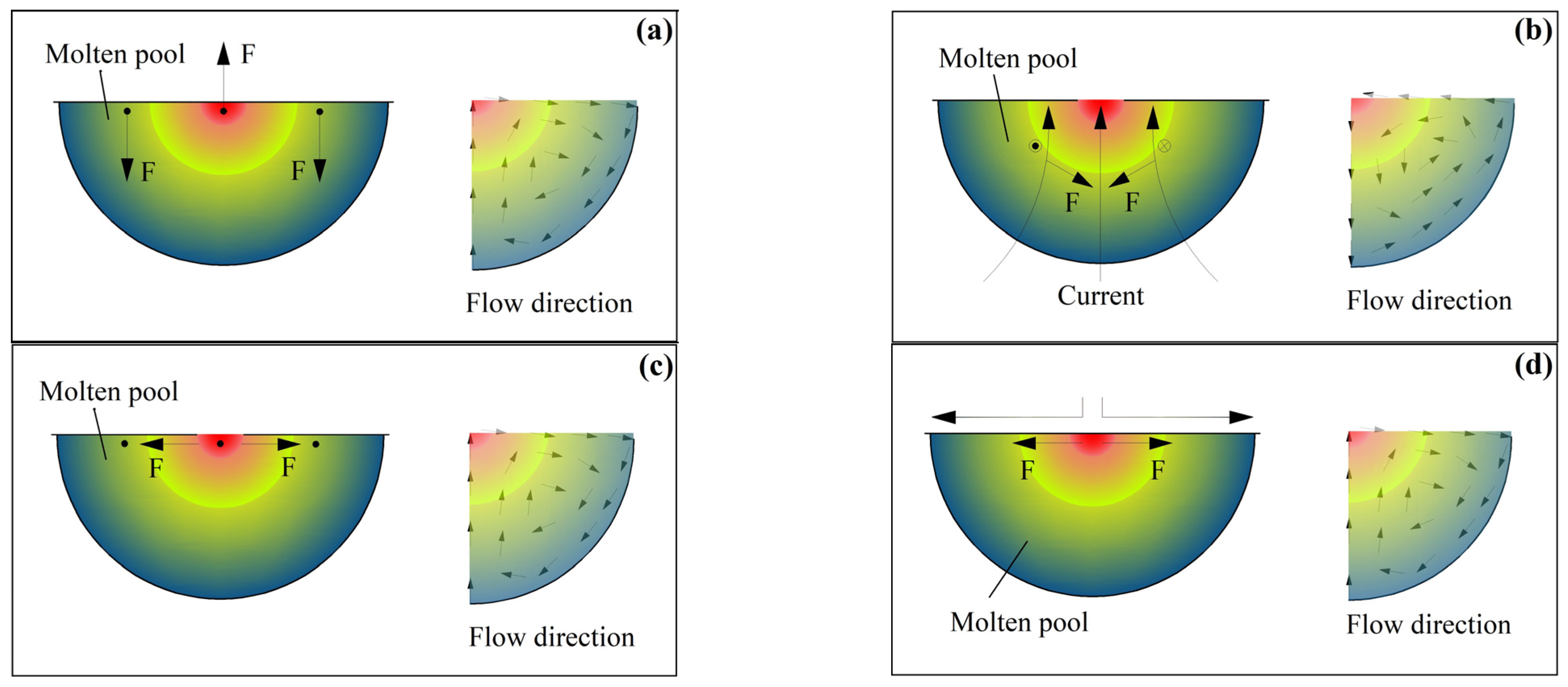
- The energy of the argon arc heat source follows a Gaussian distribution. The thicknesses of the remelted layer and the heat-affected layer increase as a function of the current . The molten pool generated by argon arc action may undergo convection under such driving forces as buoyancy, Lorentz force, surface tension, and plasma flow force. The larger the pulse current , the greater the driving forces, and the more intense the convection in the molten pool. Then, air is more likely to be drawn into the solution, forming pores. The convection of the molten pool does not cause macroscopic element segregation.
- (2)
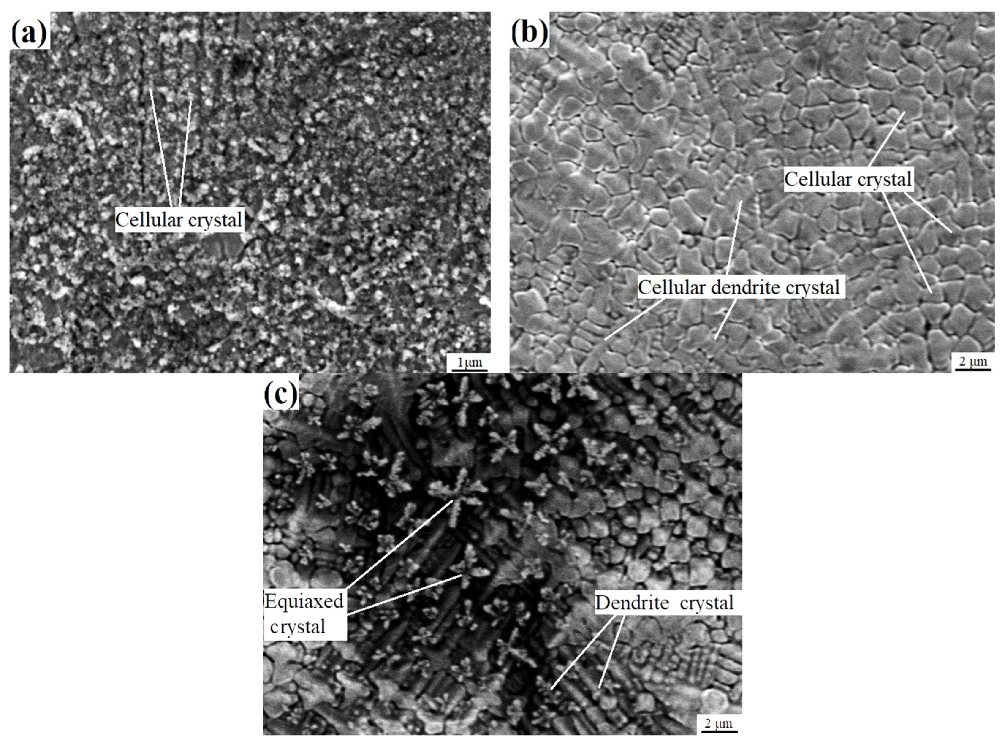
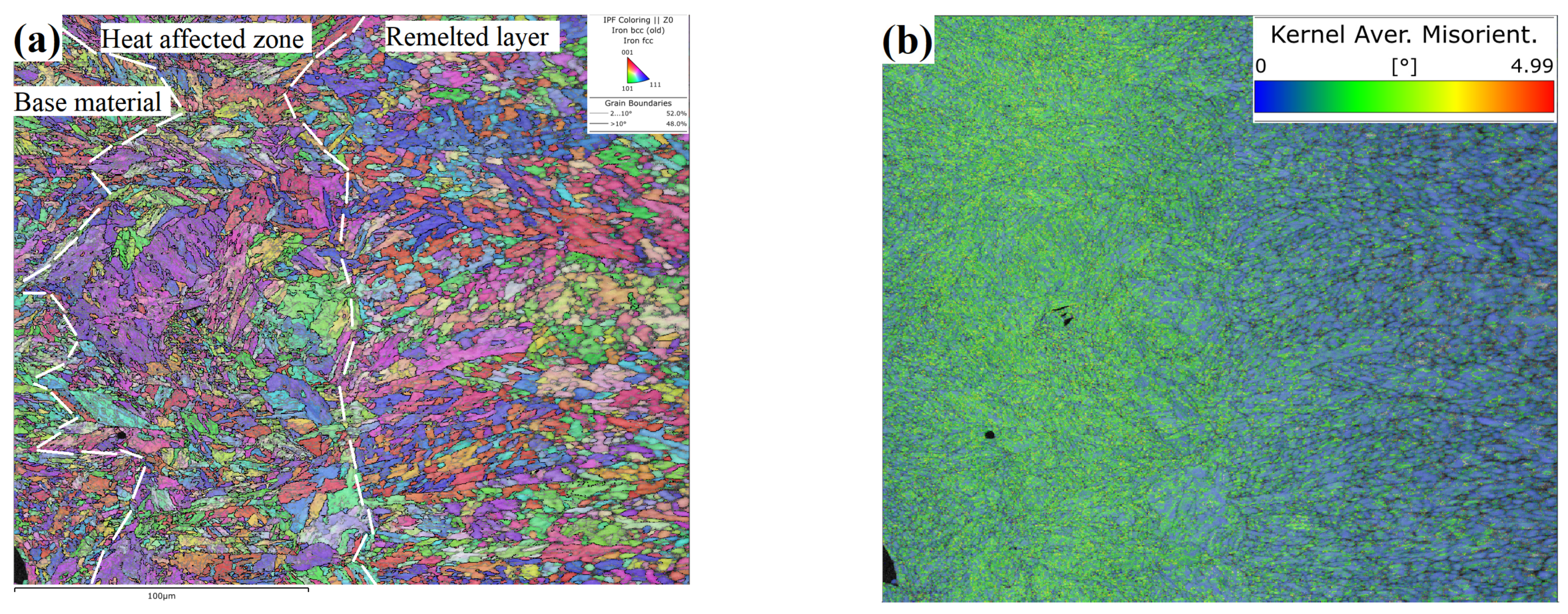
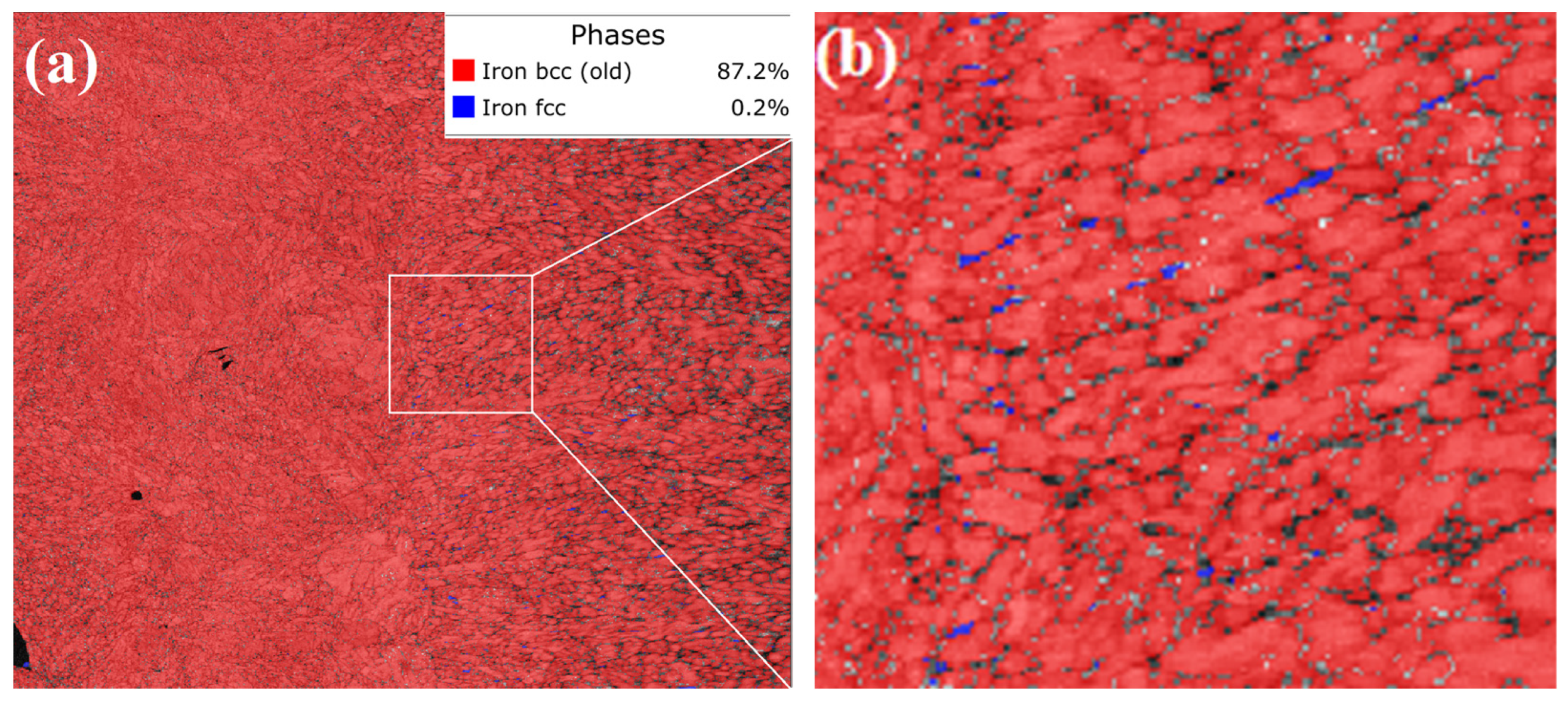
- From the bottom of the molten pool to the center of the remelted layer, grain morphologies were in the order of cellular crystals, cellular dendritic crystals, dendritic crystals, and equiaxed crystals. So, the grain size gradually increases. The solidification mode of the remelted layer was as follows: L → A → M + A′. The phase transition mode of the heat-affected zone was as follows: M + A′ → Areverse → Mtemper. Compared with the base material and heat-affected zone, the grains in the remelted layer formed a texture of <001> direction with a larger average size of 2.51 μm and a lower misorientation angle. The content of the residual austenite A′ was relatively high in the remelted layer, was distributed in the form of strips along grain boundaries, and always maintained a shear–coherent relationship with martensite.
- (3)
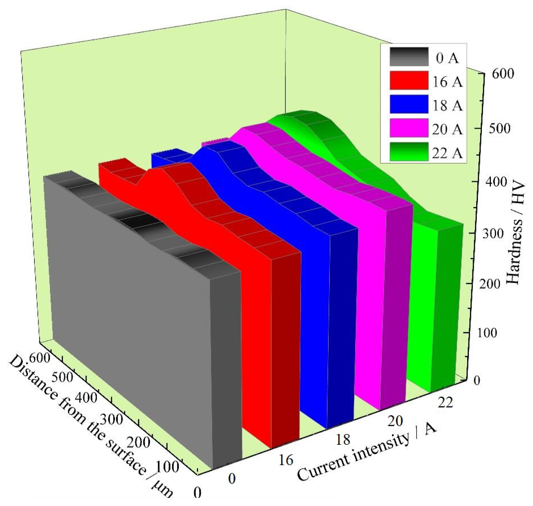
- When the pulse current I increased from 16 A to 20 A, the surface hardness of LPBF 18Ni300 increased due to the reduction in defects and the increase in the martensite phase. When the current was higher than 20 A, the convection became intense, and gas was easily drawn into the melt to form pores, leading to an increase in defects and a decrease in surface hardness. When the current was 20 A, the surface hardness was the highest, 389.0 HV, which was 11.2% higher than that of the base material. The primary factors affecting the hardness change of LPBF 18Ni300 surface argon arc remelting were pore (defect) weakening and phase transition strengthening, while the secondary factors included fine grain strengthening and texture strengthening.
Author Contributions
Funding
Institutional Review Board Statement
Informed Consent Statement
Data Availability Statement
Conflicts of Interest
References
- Emadinia, O.; Gil, J.; Amaral, R.; Lopes, C.; Rocha, R.; Reis, A. Laser Deposited 18Ni300 Alloy Powder on 1045 Steel: Effect of Passes and Preheating on Microstructure. Materials 2022, 15, 1209. [Google Scholar] [CrossRef] [PubMed]
- Xu, Q.X.; Zheng, D.Y.; Chen, X.; Konovalov, S.; Chen, X.Z. Microstructure and Mechanical Properties of Laser Clad 18Ni300 Coatings with La2O3 Addition on ZL205A Aluminum Alloy. Journal of Surface Investigation. X-Ray Synchrotron Neutron Tech. 2024, 18, 495–505. [Google Scholar]
- Wang, S.B.; Wang, Z.D.; Yang, K.; Chen, M.Z.; Wu, E.K.; Ni, Z.H.; Sun, G.F. Investigation of on-site repair of 18Ni300 by underwater laser direct metal deposition technique. J. Manuf. Process. 2022, 80, 909–919. [Google Scholar] [CrossRef]
- Fernandes, R.F.; Joel, D.J.; Borrego, L.; Vilhena, L.; Ramalho, A.; Ferreira, J.A. Influence of Deposition Plane Angle and Saline Corrosion on Fatigue Crack Growth in Maraging Steel Components Produced by Laser Powder Bed Fusion. Metals 2022, 12, 433. [Google Scholar] [CrossRef]
- Zhao, Z.J.; Wang, L.; Kong, D.C.; Liu, P.F.; He, X.; Ni, X.Q.; Zhang, L.; Dong, C.F. Texture dependence on the mechanical properties of 18Ni300 maraging steel fabricated by laser powder bed fusion. Mater. Charact. 2022, 189, 111938. [Google Scholar] [CrossRef]
- Luis, M.S.; Joel, D.J.; Ferreira, J.M.; Costa, D.J.; Capela, C. Fracture Toughness of Hybrid Components with Selective Laser Melting 18Ni300 Steel Parts. Appl. Sci. 2018, 8, 1879. [Google Scholar] [CrossRef]
- Huang, G.; Wei, K.W.; Deng, J.F.; Zeng, X.Y. High power laser powder bed fusion of 18Ni300 maraging steel: Processing optimization, microstructure and mechanical properties. Mater. Sci. Eng. A 2022, 856, 143983. [Google Scholar] [CrossRef]
- Wang, Y.; Guo, W.; Li, H.X.; Xie, Y.K.; Shi, J.X.; Liang, Z.; Han, P.P.; Li, S.J.; Zhang, H.Q. Nano-scale microstructural evolution and mechanical property enhancement mechanism during crack inhibition in nickel-based superalloys fabricated by laser powder bed fusion. Addit. Manuf. 2025, 100, 104685. [Google Scholar] [CrossRef]
- No, G.W.; Jeong, J.; Ryu, G.H.; Seol, J.B.; Kim, J.G. Mechanical Properties and Microstructure of Laser Powder Bed Fusion-Processed 18Ni300 Maraging Steel According to Direct Aging Treatment Conditions. Steel Res. Int. 2024, 96, 2400348. [Google Scholar] [CrossRef]
- Maurya, H.S.; Marczyk, J.; Juhani, K.; Sergejev, F.; Kumar, R.; Hussain, A.; Akhtar, F.; Hebda, M.; Prashanth, K.G. Binder jetting 3D printing of green TiC-FeCr based cermets—Effect of sintering temperature and systematic comparison study with Laser powder bed fusion fabricated parts. Mater. Today Adv. 2025, 25, 100562. [Google Scholar] [CrossRef]
- Bharat, M.; Arvid, S.; Lar, N. Laser Powder Bed Fusion of an Al-Mg-Sc-Zr Alloy: Manufacturing, Peak Hardening Response and Thermal Stability at Peak Hardness. Metals 2021, 12, 57. [Google Scholar] [CrossRef]
- Maodzeka, D.K.; Olakanmi, E.O.; Mosalagae, M.; Devon, H.H.; Pityana, S.L. Hybrid optimisation studies on the microstructural properties and wear resistance of maraging steel 1.2709 parts produced by laser powder bed fusion. Opt. Laser Technol. 2023, 159, 108914. [Google Scholar] [CrossRef]
- Sangoi, K.; Nadimi, M.; Song, J.; Fu, Y. Heat Treatment Effect on the Corrosion Resistance of 316L Stainless Steel Produced by Laser Powder Bed Fusion. Metals 2025, 15, 41. [Google Scholar] [CrossRef]
- Wang, J.; Ma, M.; Yigit, K.; Si, Q.Y.; Liang, C.Y.; Sun, Q.Y.; Xie, Y.P.; Wang, S.; Li, Z.F. Secondary electron yield reduction of 316L stainless steel prepared by selective laser melting and surface remelting for electron cloud inhibition. Vacuum 2024, 229, 113573. [Google Scholar] [CrossRef]
- Hixson, W.R.; Yu, J.Y.; Wilson, A.; Stone, H.J.; Isheim, D.; Coakley, J. Eutectic composition titanium metal matrix composites for laser powder bed fusion via surface remelt analyses. Mater. Sci. Technol. 2023, 39, 1650–1660. [Google Scholar] [CrossRef]
- Shi, W.T.; Wang, P.; Liu, Y.D.; Hou, Y.J.; Han, G.L. Properties of 316L formed by a 400 W power laser Selective Laser Melting with 250 μm layer thickness. Powder Technol. 2020, 360, 151–164. [Google Scholar] [CrossRef]
- Xiang, Z.W.; Yan, R.; Wu, X.Y.; Du, L.Q.; Yin, Q. Surface morphology evolution with laser surface re-melting in selective laser melting. Optik 2020, 206, 164316. [Google Scholar] [CrossRef]
- Zhou, J.T.; Li, M.; Yang, X.; Shen, W.; Wu, G.; Ming, X.; Wu, S.J. In-situ laser surface remelting of laser powder bed fused AlSi10Mg alloy at argon and nitrogen protective gases: Multiscale analysis. Opt. Laser Technol. 2025, 181, 111631. [Google Scholar] [CrossRef]
- Ivan, A.D.; Ivan, V.S.; Denis, A.O.; Konstantin, V.G. Structural-phase state and microhardness of the surfacing formed on a steel substrate by pulsed argon tungsten arc remelting of Cu-tube containing W-Ta-Mo-Nb-Zr-Cr-Ti powder mixture. Intermetallics 2025, 179, 108639. [Google Scholar]
- Li, Y.L.; Dong, T.S.; Li, G.L.; Wang, H.D.; Fu, B.G.; Zheng, X.D.; Zhou, X.K. Microstructure and mechanical property of Ni-based thick coating remelted by gas tungsten arc. Vacuum 2018, 155, 260–269. [Google Scholar]
- Ma, Y.X.; Gao, Y.F.; Zhang, H.; Men, Z.X.; Yang, L.X. A comprehensive study on the microstructure evolution and mechanical property characterization of selective laser melted 18Ni300 stainless steel during heat treatment processes. J. Mater. Res. Technol. 2024, 33, 51–60. [Google Scholar] [CrossRef]
- Ludmila, K.; Ivana, Z.; ŠJeníček, T.; Karolína, B. Hybrid parts produced by deposition of 18Ni300 maraging steel via selective laser melting on forged and heat treated advanced high strength steel. Addit. Manuf. 2020, 32, 101108. [Google Scholar]
- Chen, R.; Wang, H.M.; Li, J.; He, B.; Shao, W.P.; Zhang, S.Q. Effect of laser remelting and heat treatment on microstructure and wear resistance of 2A97 Al-Li alloy. Surf. Interfaces 2022, 33, 102197. [Google Scholar] [CrossRef]
- Yang, J.L. Selective laser melting additive manufacturing of advanced nuclear materials V-6Cr-6Ti. Mater. Lett. 2017, 209, 268–271. [Google Scholar]
- Meng, X.M.; Qin, G.L.; Zou, Z.D. Sensitivity of driving forces on molten pool behavior and defect formation in high-speed gas tungsten arc welding. Int. J. Heat Mass Transf. 2017, 107, 1119–1128. [Google Scholar] [CrossRef]
- Cho, W.I.; Na, S.J. Impact of driving forces on molten pool in gas metal arc welding. Weld. World 2021, 65, 1735–1747. [Google Scholar] [CrossRef]
- Huang, J.H. Principles of Welding Metallurgy; China Machine Press: Beijing, China, 2015; p. 38. [Google Scholar]
- Han, S.W.; Cho, W.I.; Na, S.J.; Kim, C.H. Influence of driving forces on weld pool dynamics in GTA and laser welding. Weld. World J. Int. Inst. Weld. 2013, 57, 257–264. [Google Scholar] [CrossRef]
- Qu, M.L.; Yuan, J.D.; Nabaa, A.; Huang, J.Y.; Chihpin, A.C.; Chen, L.Y. Melting and solidification dynamics during laser melting of reaction-based metal matrix composites uncovered by in-situ synchrotron X-ray diffraction. Acta Mater. 2024, 271, 119875. [Google Scholar] [CrossRef]
- Liu, W.P.; Chen, L.P.; Zhou, Q.; Yuan, Y.P.; Liu, Y.X. Effects of Zn and Sr compound treatment on microstructure and properties of WE43 magnesium alloy. Chin. J. Spec. Cast. Nonferr. Alloys 2023, 43, 1555–1560. [Google Scholar]
- Bai, J.F.; Wang, Q.L.; Men, Z.X.; Chen, W.; Huang, H.J.; Ji, C.; Li, Y.; Wang, L.; Zhu, L.; Li, K.; et al. Generation Mechanism of Anisotropy in Mechanical Properties of WE43 Fabricated by Laser Powder Bed Fusion. Micromachines 2024, 15, 976. [Google Scholar] [CrossRef]
- Xiang, C.; Zhang, T.; Wu, W.W.; Zou, Z.H.; Sun, Y.F.; Liu, J.P.; Xu, X.L.; Han, E.H. Effect of Heat Treatment on Microstructure and Mechanical Properties of Selective Laser Melting 18Ni300 Maraging Steel. Chin. J. Lasers 2024, 51, 176–185. [Google Scholar]
- Wu, W.W.; Xiang, C.; Zhang, T.; Zou, Z.L.; Sun, Y.F.; Liu, J.P.; Zhang, T.; Han, E.H. Effect of Heat Treatment on Microstructure and Tensile Properties of 18Ni300 Maraging Steel Fabricated by Selective Laser Melting. Acta Metall. Sin. 2024. [Google Scholar] [CrossRef]
- Cayron, C.; Barcelo, F.; Carlan, Y.D. The mechanisms of the fcc–bcc martensitic transformation revealed by pole figures. Acta Mater. 2010, 58, 1395. [Google Scholar] [CrossRef]
- Knudsen, F.P. Dependence of Mechanical Strength of Brittle Polycrystalline Specimens on Porosity and Grain Size. J. Am. Ceram. Soc. 1959, 42, 376–387. [Google Scholar] [CrossRef]
- Noboru, Y.; Kohsaku, S.; Naoki, I.; Sergey, K.; Kashimura, K.; Takashi, F.; Hideoki, F. Complex permittivity and microwave heating behavior of rod-shaped SiC and oxide (SiO2, Al2O3) mixtures. Mater. Chem. Phys. 2019, 234, 281–287. [Google Scholar]
- Tian, L.Y.; Zong, X.Y.; Zhao, J.C.; Guan, S.Y.; Li, C.; Zhao, Z.R.; Zhang, S.Z. Microstructure and mechanical properties of Ti/Al3Ti metal-intermetallic laminate (MIL) composites with different ductile phase volume fractions prepared by hot-pressing. Mater. Charact. 2025, 219, 114586. [Google Scholar] [CrossRef]
- Zhu, H.M.; Ben, X.; Li, B.C.; Shen, L.Z.; Pan, C.L.; Qiu, C.J. Influence of Al microalloying on microstructure and mechanical properties of laser directed energy deposited AISI 420 steel. Mater. Today Commun. 2025, 42, 111355. [Google Scholar] [CrossRef]
- Sanjib, B.; Sanjib, G.; Harun, R.S.; Sushen, K.; Satadru, K.; Rakesh, B. Development of Hall-Petch and Hollomon models for thermo-mechanically treated Al-Cu-Mg alloys with trace additions of Sn. Adv. Mater. Process. Technol. 2024, 10, 2895–2917. [Google Scholar]
- Huang, Y.; Pan, H.C.; Pan, Z.; Zeng, Z.H.; Tang, W.N.; Yang, C.B.; Du, S.; Ren, Y.P.; Qin, G.W. Effect of pre-stretching on enhancing yield strength of as-extruded Mg-Sm-Ce based alloy. J. Alloys Compd. 2023, 968, 171869. [Google Scholar] [CrossRef]
- Dong, D.D.; Chang, C.; Wang, H. Selective Laser Melting (SLM) of CX Stainless Steel: Theoretical Calculation, Process Optimization and Strengthening Mechanism. J. Mater. Sci. Technol. 2021, 73, 151–164. [Google Scholar] [CrossRef]


| Elements | Ni | Ti | Co | Al | Mo | Si | Cr | Mn | C | Fe |
|---|---|---|---|---|---|---|---|---|---|---|
| Content | 17.70 | 0.72 | 9.05 | 0.077 | 4.70 | 0.025 | 0.031 | 0.022 | 0.007 | Bal. |
| Current Intensity/A | 16 | 18 | 20 | 22 |
|---|---|---|---|---|
| Thickness of remelted layer/μm | 308 ± 7 | 333 ± 4 | 352 ± 5 | 381 ± 16 |
| Thickness of heat-affected layer/μm | 87 ± 7 | 92 ± 12 | 98 ± 4 | 117 ± 13 |
| Elements | Fe | Ni | Co | C | Mo | O |
|---|---|---|---|---|---|---|
| Content | 59.0 ± 1.1 | 16.1 ± 1.2 | 9.3 ± 0.2 | 7.4 ± 0.2 | 4.8 ± 0.2 | 2.9 ± 0.1 |
Disclaimer/Publisher’s Note: The statements, opinions and data contained in all publications are solely those of the individual author(s) and contributor(s) and not of MDPI and/or the editor(s). MDPI and/or the editor(s) disclaim responsibility for any injury to people or property resulting from any ideas, methods, instructions or products referred to in the content. |
© 2025 by the authors. Licensee MDPI, Basel, Switzerland. This article is an open access article distributed under the terms and conditions of the Creative Commons Attribution (CC BY) license (https://creativecommons.org/licenses/by/4.0/).
Share and Cite
Zeng, X.; Sun, Y.; Zhang, H.; Jia, Z.; Kang, Q. A Mechanism of Argon Arc Remelting of LPBF 18Ni300 Steel Surfaces. Coatings 2025, 15, 481. https://doi.org/10.3390/coatings15040481
Zeng X, Sun Y, Zhang H, Jia Z, Kang Q. A Mechanism of Argon Arc Remelting of LPBF 18Ni300 Steel Surfaces. Coatings. 2025; 15(4):481. https://doi.org/10.3390/coatings15040481
Chicago/Turabian StyleZeng, Xiaoping, Yehui Sun, Hong Zhang, Zhi Jia, and Quan Kang. 2025. "A Mechanism of Argon Arc Remelting of LPBF 18Ni300 Steel Surfaces" Coatings 15, no. 4: 481. https://doi.org/10.3390/coatings15040481
APA StyleZeng, X., Sun, Y., Zhang, H., Jia, Z., & Kang, Q. (2025). A Mechanism of Argon Arc Remelting of LPBF 18Ni300 Steel Surfaces. Coatings, 15(4), 481. https://doi.org/10.3390/coatings15040481