Article

Preparation of High-Entropy Silicide Coating on Tantalum Substrate by Silicon Infiltration Method and Its Antioxidant Performance

1
School of Materials Science and Engineering, Central South University, Changsha 410083, China
2
State Key Laboratory of Special Rare Metal Materials, Northwest Rare Metal Materials Research Institute Ningxia Co., Ltd., Shizuishan 753000, China
*
Author to whom correspondence should be addressed.
Coatings 2025, 15(4), 476; https://doi.org/10.3390/coatings15040476
Submission received: 25 February 2025 / Revised: 11 April 2025 / Accepted: 14 April 2025 / Published: 17 April 2025
(This article belongs to the Section Ceramic Coatings and Engineering Technology)

Abstract

:
High-entropy silicide (MeSi2) coating was prepared by the slurry method and silicon infiltration method using Mo, Cr, Ta, Nb, W, and Si elemental powders as raw materials. The coating consisted of four layers, including a porous MeSi2 layer, a (CrTa)Si layer, a TaSi2 layer, and a Ta5Si3 layer from outside to inside. At 600 °C, Si was preferentially oxidized to form SiO2 oxide film. The mass gain rate of the coating was 0.2 mg/cm2 over a period of 100 h oxidation, eliminating the phenomenon of low-temperature pulverization. At 1200 °C, MeSi2 coating had a protection time of 20 h. During the oxidation process, the coating generated metal oxides, forming a thin SiO2 oxide film. TaSi2 and Ta5Si3 gradually transformed into Ta2O5, and the coating eventually failed.

1. Introduction

Tantalum and its alloys have excellent high-temperature mechanical properties (high-temperature strength and creep resistance, etc.) and good room temperature performance, making them potential application materials for ultra-high-temperature component structural materials, and are especially applied in the aerospace industry [1,2]. However, the poor oxidation resistance of Ta and Ta alloys in high-temperature service environments limits the service range and lifespan of related components. To improve oxidation resistance, researchers have carried out a lot of work. Surface antioxidation coating has become one of the important means in the current thermal protection technology field of tantalum materials, with broad application prospects and good development potential. Song et al. [3] prepared Si-Ti coatings on the surface of a Ta alloy using the melt slurry method. Dong et al. [4] prepared ZrB2 antioxidant ceramic coating on a Ta-W alloy surface using a two-step method. Majumda et al. [5] prepared a 40 μm multi-layer Al-Si composite coating on the surface of tantalum using embedding infiltration technology. Cai et al. [6] prepared MoSi2-TaSi2 ceramic coatings on pure Ta substrates using a three-step method. Yoon et al. [7] prepared nano Si3N4 particle reinforced TaSi2 coating on the surface of a Ta substrate through in situ displacement reaction between Ta nitrides (TaN and Ta2N) and Si.
Silicide coatings are currently the most used coating systems in the field of high-temperature oxidation resistance [6,7,8,9,10]. Their oxidation resistance mechanism mainly relies on the formation of a dense SiO2 oxide film at high temperatures. The Gibbs free energy of the reaction between Si and oxygen at high temperatures is low, and the fluidity of the SiO2 formed by the reaction has the ability to “selfheal” at high temperatures. Molten SiO2 can flow into cracks and pores in the coating, improving the density of the SiO2 oxide film, preventing oxygen diffusion to the substrate, and continuously protecting the tantalum substrate.
MoSi2 coating has excellent antioxidant properties and self-healing ability at high temperature, making it the most used antioxidant coating system for tantalum and tantalum alloys. However, MoSi2 coating shows a ‘pesting’ phenomenon at low temperature [10]. When the temperature is between 400 and 600 °C, the diffusion coefficient of Si in MoSi2 is low, and complete SiO2 film cannot be formed, while molybdenum is oxidized, forming powder products mainly with MoO3 whiskers (or sheets) and SiO2 clusters. Recently, high-entropy ceramic silicide has attracted a lot of attention [11]. As reported, high-entropy ceramic silicide can eliminate the ‘pesting’ phenomenon that usually appears for the single-silicide coating [12] and has advantages as a high-temperature oxidation resistance material [13]. The high-entropy ceramic silicide has great potential for application as a high-temperature protective coating [14]. At present, the main preparation methods for surface antioxidation coatings on tantalum and tantalum alloys include the halide embedding infiltration method, slurry sintering method, spray coating method, surface cladding method, etc. The halide embedding infiltration method uses gaseous halides as carriers to infiltrate protective elements (Si, B, etc.) into the surface of tantalum and tantalum alloys, forming protective coatings. The coating and substrate interface prepared by the embedding infiltration method have high bonding strength, a dense structure, a low oxygen permeation rate, and good oxidation resistance. Therefore, in this study, a (Mo0.2Cr0.2Ta0.2Nb0.2W0.2)Si2 high-entropy silicide ceramic coating on a tantalum substrate was prepared using the slurry sintering method and halide embedding infiltration method, and the oxidation behaviors of the coating at 600 °C and 1200 °C were evaluated.

2. Experimental Details

2.1. Preparation of Precursor Powders

Equal atom contents of Mo, Cr, Ta, Nb, and W powders with an initial particle size of no more than 325 mesh were weighed. First, the powders were mixed thoroughly in a mixer at 120 r/min for 24 h. After mixing, the powders were placed in a ball milling jar under argon protection environment. The ball-to-material ratio was 10:1. The milling time was 60 h with a speed of 400 rpm.

2.2. Preparation of Coating

Firstly, a high-entropy alloy coating was prepared using slurry method. The slurry was composed of elemental metal precursor powders, anhydrous ethanol, PVB, and silicon powders with a mass ratio of 42:52:1:5. The mixture was subjected to wet grinding, with a ball mill rotation speed of 200 rpm, a ball powder mass ratio of 5:1, and a ball milling time of 2 h. After wet grinding, the slurry was evenly brushed onto the surface of the tantalum substrate, and the sample was dried, and a coating with thickness of 100 μm could be obtained by repeating 4 times. Then the samples were dried and sintered in a vacuum sintering furnace. The furnace was heated from room temperature to 1420 °C for 1.5 h with a pressure of 1 × 10⁻³ Pa. Then the samples with sintered high-entropy alloy coating were placed in a sealed corundum crucible filled with a filler mass ratio (Si:NaF:Al2O3 = 30:5:65) and sintered at 1200 °C under an argon atmosphere for 2 h to obtain a MeSi2 coating.

2.3. Oxidation Test

The antioxidant experiments were conduct on a muffle furnace at temperatures of 600 °C and 1200 °C. Before testing, the surface area of each coating sample was measured using a vernier caliper, then the samples were placed in an alumina crucible and measured for initial mass. Subsequently, the samples were transferred to a muffle furnace (SG-G03143, Zhonghuan Electric Furnace Co., Ltd., Tianjin, China) preheated to 600 and 1200 °C. At regular intervals, the samples were taken out and weighed. Then the mass change was calculated by dividing the change of weight by its surface area. To eliminate errors, 5 samples were tested to obtain the average value. The oxidation weight gain per unit area of the sample was calculated according to Formula (1):
Δ W = m 1 m 0 × 100 % S
In the formula, ΔW is the oxidation weight gain per unit area of the coating sample (mg/cm2); m0 is the initial mass of the sample (mg); m1 is the mass of the oxidized sample (mg); S is the surface area of the sample (cm2).

3. Results and Discussion

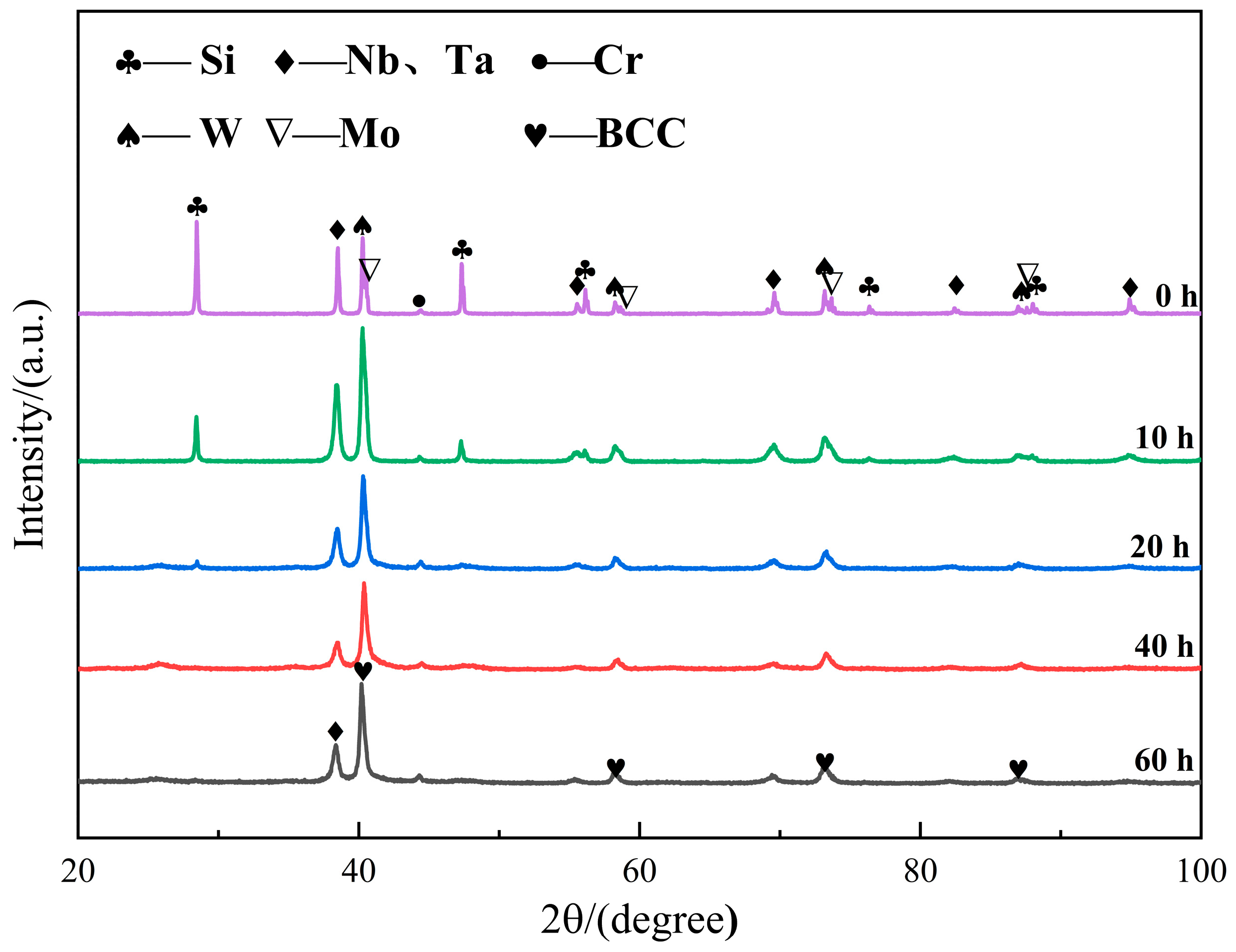
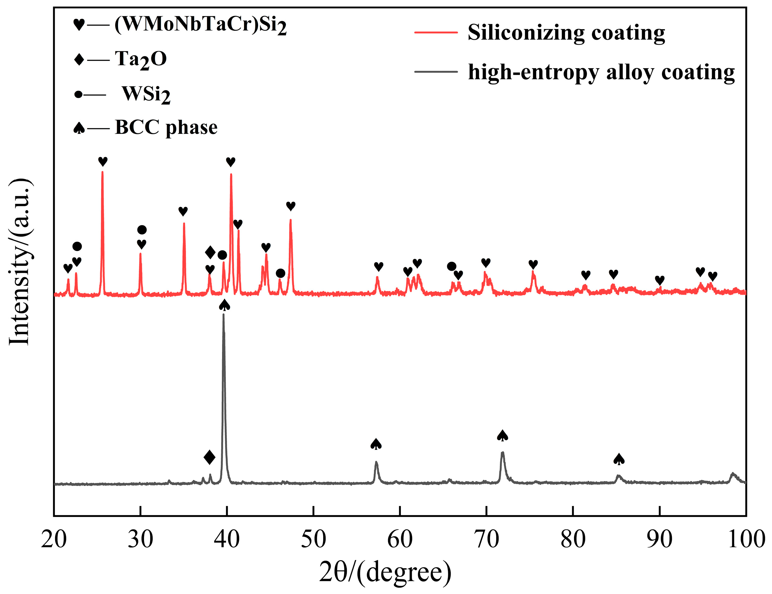
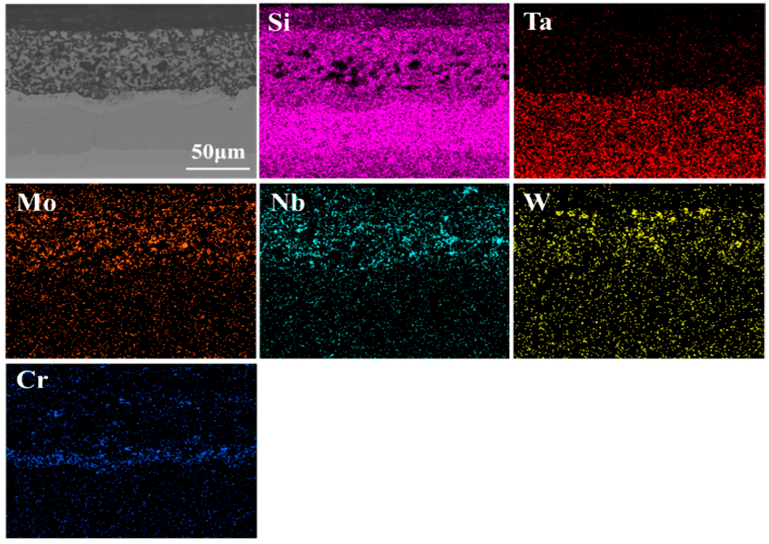
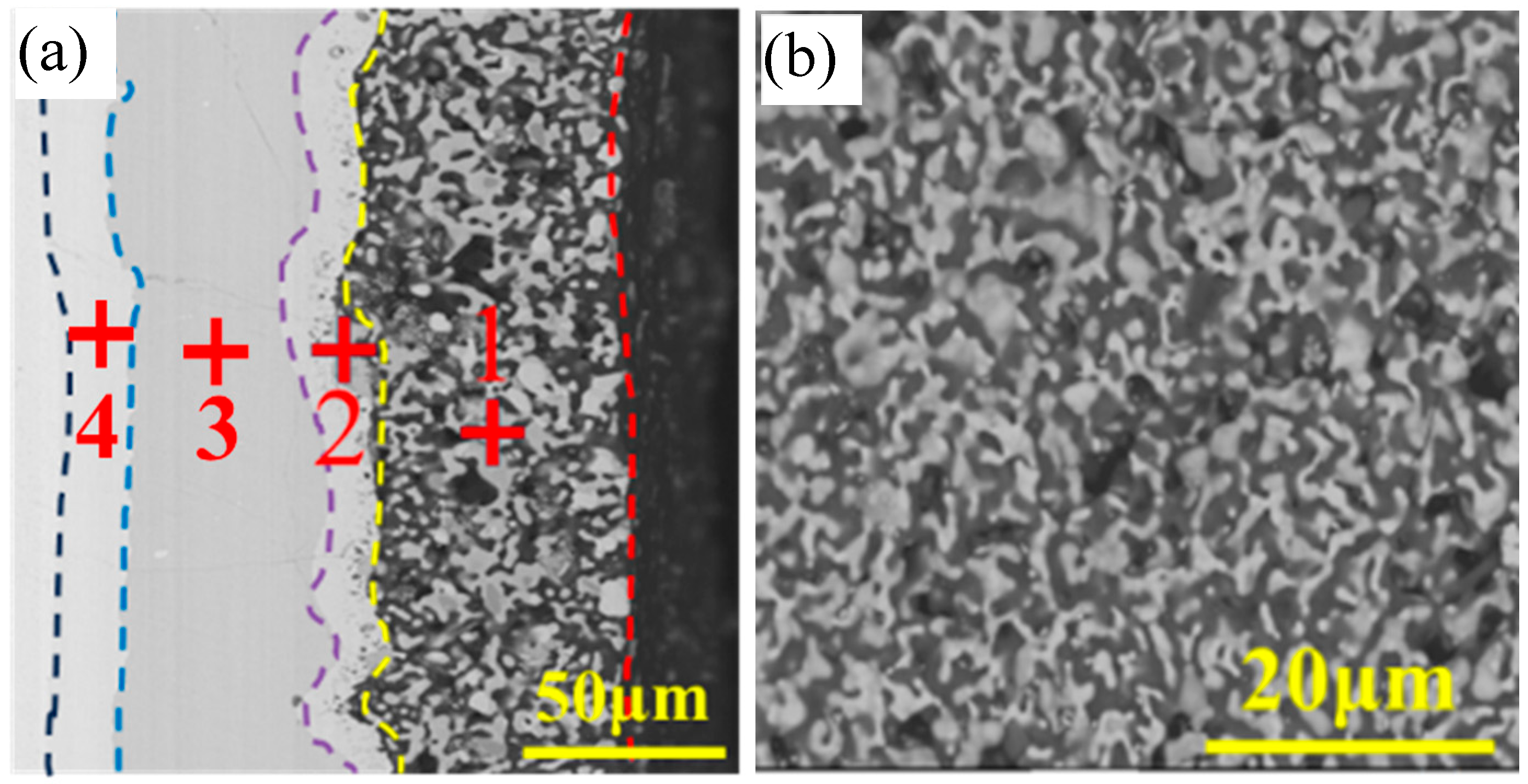
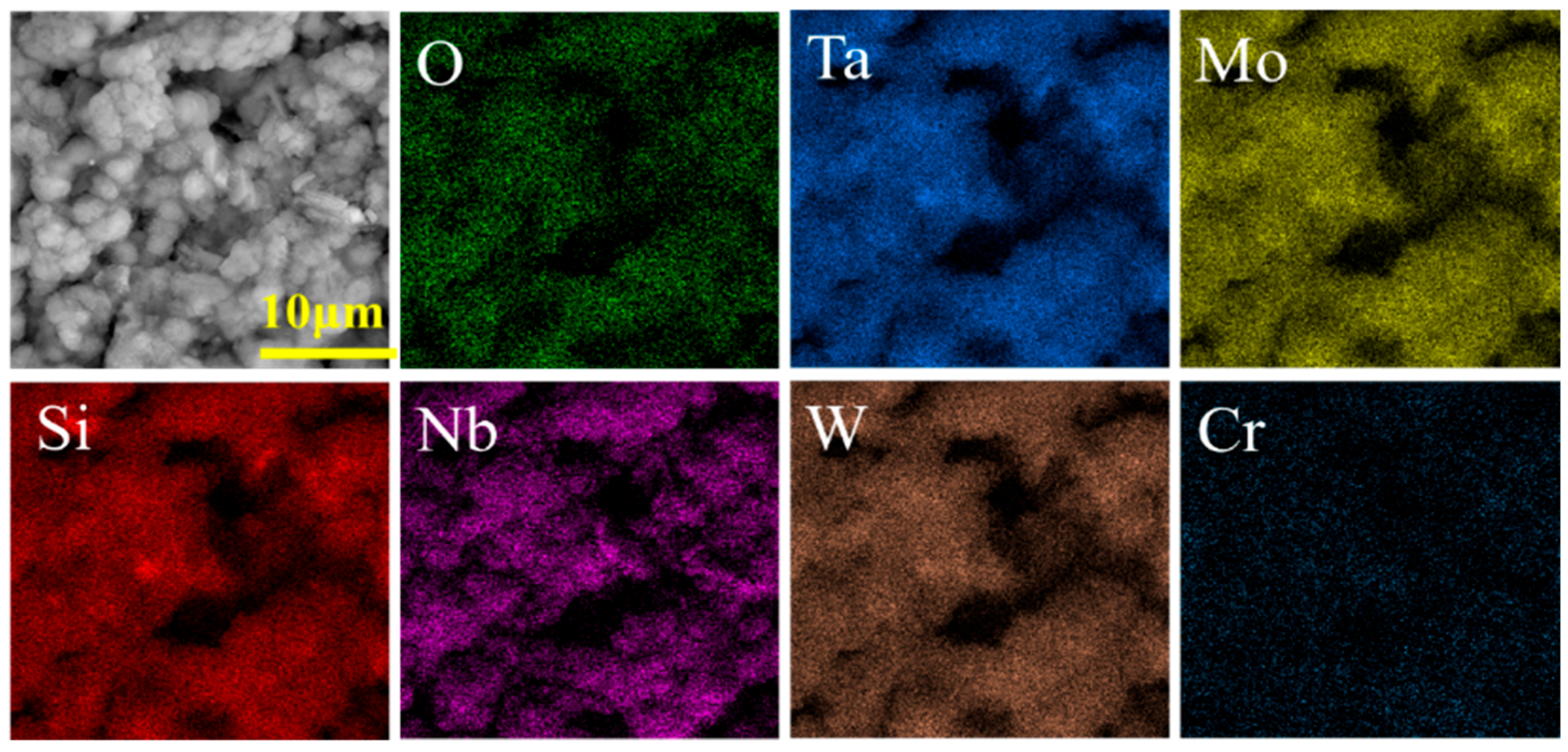
3.1. Microstructure and Composition of Coatings

Figure 1 shows the XRD diffraction patterns of the elemental powders after different ball milling times. At the beginning, diffraction peaks of each element could be clearly detected in the mixed powder. After ball milling for 10 h, the width of the diffraction peaks slightly increased while the intensity of some peaks changed. The intensity of Si and Cr elements rapidly decreased, indicating the gradual formation of a solid solution. The changes in width and diffraction angle of the peaks represented the lattice distortion of the powder. In the solid-state reaction process, the alloying rate between various elements is mainly affected by the melting point of the elements, mechanical fragmentation between particles, and solid-state diffusion between elements. The lower the melting point of the elements is, the faster the alloying rate will be. Elements with higher melting points have smaller intrinsic diffusion coefficients, resulting in slower alloying rates. In addition, the interactions between different elements also have a certain impact on the diffusion rate, and negative mixing enthalpy is conducive to increasing the diffusion rate and promoting the solid solution process. It was found in the literature that Mo, Nb, Ta, Cr, W, and Si all had negative mixing enthalpies [15], resulting in decreases in the diffraction peaks of Si, Nb, Ta, Cr, and Mo. When the ball milling time reached 20 h, as the ball milling time continued to extend, the grains were further refined and the enthalpy stored at the grain boundaries increased, thereby accelerating the diffusion and solid solution processes. The peaks of Si and Cr elements completely disappeared, and the peaks of the mixed powders were mainly corresponding to a solid solution with the BCC structure as reported [16], with only the Ta and W elements being clearly detectable. When the ball milling time reached 40 h, the main diffraction peaks shifted right to 40.301°, and the intensity of the peak increased. After milling for 60 h, the peak continued to shift right to 40.367°. Then the effect of prolonging ball milling time was not significant, and the changes in the XRD pattern were no longer obvious.
Figure 2 shows the SEM image of the powers after milling for 60 h and the EDS map images of the elemental powders, in which Ta, Nb, Mo, Ta, and Cr elements are uniformly distributed. However, a small amount of the W element was enriched, which may have been related to the high melting point of W.
The sintering procedure of the slurry with elemental metal powder on the Ta substrate was 1420 °C and kept for 1.5 h. Then the sintered sample was placed in a corundum crucible, filled with filler (Si:NaF:Al2O3 = 30:5:65 wt%), and sealed with a high-temperature repair adhesive. According to reference [17], the silicon infiltration temperature and time were set to be 1200 °C for 2 h. The XRD patterns for the samples before and after silicon infiltration are present in Figure 3. The ball-milling metal powers after sintering formed a high-entropy alloy with a BCC structure, with only a small amount of the Ta2O phase present. After silicon infiltration, a MeSi2 phase formed on the surface. In addition, some WSi2 phase had been observed due to the insoluble W element during the ball milling process.
Figure 4 shows the SEM images and the cross-sectional EDS spectrum of MeSi2 coating. The coating consisted of four layers. Metal elements were mainly distributed in the outermost layer while tantalum and silicon elements were distributed in each layer, indicating the formation of other silicides. It is worth mentioning that the Cr element was enriched in the second layer from the outside to the inside. The rapid diffusion of Si led to the formation of many vacancies in the interface between the outer and inner layers. Except for Si, the melting point of Cr element was the lowest among the metal elements, so the Cr element had faster diffusion rate than other metals. In the interface, Cr reacted with Ta and Si to form a small number of intermetallic compounds [18,19].
The EDS energy spectrum analysis results of the MeSi2 coating cross-section are shown in Table 1. The elements in region 1 are Si and metallic elements, with an atomic ratio of approximately 2:1, and the proportions of the Si, Cr, Nb, Mo, Ta, and W elements conform to the nominal molar ratio of MeSi2. Based on the XRD pattern in Figure 3, it can be concluded that the outer layer had formed high-entropy silicide. Below the outermost layer, the element contents of Cr and Ta were relatively high. This was because when sintering, Si diffused and reacted quickly with the metal elements of the coating, leading to numerous vacancies in the coating. Cr, with the lowest melting point among the metal elements, has the fastest diffusion rate. So, Cr diffused along the vacancies. Therefore, a distribution of Cr elements in the Ta5Si3 layer and TaSi2 were also observed. The atomic ratio of Si and Ta in the layer where point 3 is located in Figure 5 was about 2:1, indicating the formation of a TaSi2 phase. For point 4, the atomic ratio of Si to Ta in the inner layer was about 3:5, forming the low silicide of Ta5Si3. The reason for its formation was that during the sintering process, Si element diffused into the tantalum substrate, forming a transition layer Ta5Si3 phase at the interface of the tantalum substrate. As the temperature increased and the holding time was prolonged, Si concentration in the tantalum substrate continued to increase, and Ta5Si3 continued to react with Si element to form a TaSi2 layer.
During the silicon infiltration process, Si diffused from the embedded mixed powder to the surface of the tantalum substrate and was deposited on the surface. The possible reactions that may have occurred in the silicon infiltration process were as follows:
Si ( s ) + xNaF ( l ) Si F x ( g ) + xNa ( g )
2 Si F x ( g ) 2 Si ( s ) + x F 2 ( g )
Si F x   ( g ) + xNa ( g ) Si ( g ) + xNaF ( l )
( x + 1 ) Si F x ( g ) Si ( s ) + xSi F x + 1 ( g )
2 Si ( s ) + Me ( s ) MeS i 2 ( s )
3 Si ( s ) + 5 Me ( s ) M e 5 S i 3 ( s )
7 Si ( s ) + M e 5 S i 3 ( s ) 5 MeS i 2 ( s )
During the silicon infiltration process, high-entropy alloys (Me) tended to form low silicides with active Si first, then reacted with Si to form MeSi2.

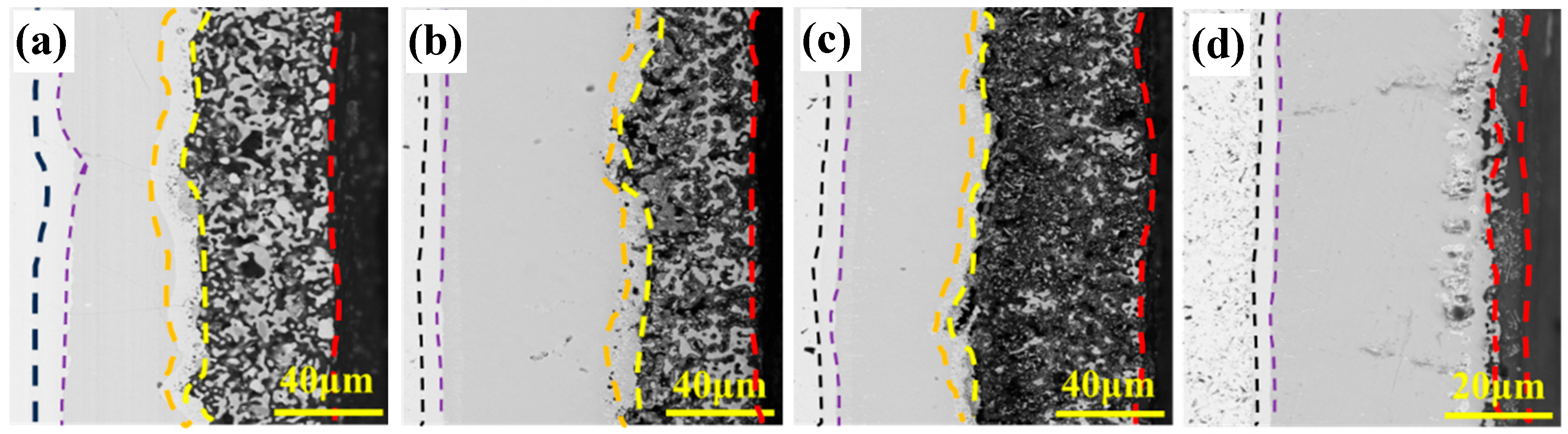
3.2. Oxidation Behavior of Coatings

The oxidation behaviors of the samples coated with MeSi2 coating at 600 and 1200 °C were tested. Figure 6 shows the cross-sectional and surface SEM morphology of the sample after 100 h of oxidation at 600 °C. The MeSi2 coating showed no significant change compared to the coating before oxidation, and the macroscopic sample remained intact. No needle-shaped MoO3 formed on the surface. The high-entropy effect in the MeSi2 coating effectively avoided material pulverization caused by the ‘pesting’ phenomenon.
Figure 7 shows the mass gain curves and surface XRD pattern of the MeSi2 coating after 600 °C oxidation for 100 h. The weight gain of the coating was 0.2 mg/cm2. In the early stage of oxidation, weight gain maintained a linear increase, and the mass growth rate began to decrease around 10 h. After several tens of hours, the mass growth rate became extremely slow. The reason may have been that a complete SiO2 oxide film gradually formed on the surface of the sample and the slow diffusion effect of high-entropy reduced the oxidation rate of the coating. In addition, the peaks in the patterns before and after coating oxidation were basically consistent, with only a small number of peak height changes. The reason for this may have been the distortion of lattice constants caused by the precipitation and oxidation of Si elements from the solid solution structure.
The XRD diffraction pattern mainly shows the phase structure of MeSi2, with only a small number of SiO2 diffraction peaks. To further determine the elemental distribution, EDS analysis was performed on the surface. Figure 8 shows the EDS elemental distribution of MeSi2 coating after low-temperature oxidation for 100 h. The distribution of elements such as W, Mo, Ta, Nb, Si, and O was relatively uniform, and only a thin SiO2 adhesion layer was formed on the surface. However, the distribution intensity of the Cr element was slightly weaker, which may have been related to the enrichment of the Cr element in the TaSi2 phase as illustrated in Figure 4.
The different diffusion coefficients of metal elements M (M = Mo, W, Cr, Ta, and Nb), Si, and O in the SiO2 layer became one of the controlling factors in the oxidation process. In the (MoWCrTaNb)Si2, five cationic elements were randomly distributed on the cationic sites, and the difference in cationic atomic radii led to severe lattice distortion, introducing many stable vacancies with high migration energy barriers and slow diffusion effects, hindering cation diffusion [20]. The reaction between Si and O always had low Gibbs free energy between 0 K and 2000 K, and the reaction could occur spontaneously; The Gibbs free energy is much lower than that of other metal elements reacting with oxygen [19]. No other metal oxides were observed in the XRD pattern. The low-temperature oxidation process of MeSi2 was not only influenced by Gibbs free energy but also controlled by the diffusion rates of elements. It has been proven that the high-entropy effect in high-entropy silicides under low-temperature oxidation environments promotes the selective oxidation of the O element to the Si element and inhibits the oxidation of metal elements. Under the combined action of Gibbs free energy and the high-entropy effect, the formation rate of SiO2 is higher than that of metal oxides, and a complete SiO2 protective film gradually forms on the surface of MeSi2, which hinders the occurrence of the “pesting” phenomenon.
Figure 9 shows the cross-sectional morphology of the MeSi2 coating oxidized at 1200 °C for different times. In the initial stage, the Si element from MeSi2 in the coating and oxygen element reacted, generating SiO2. When SiO2 was molten, it had a certain fluidity, filling the pores inside the coating and improving the density of the coating to a certain extent. MeSi2 gradually transformed into Me5Si3, and some pores appeared in the second layer (Figure 9b).
During the late stage of oxidation, oxygen diffused through the pores, causing oxidation reactions inside the coating. Metal elements were oxidized and metal oxides sublimated at high temperatures. As the oxidation time was further extended to 10 h, the original diffusion layer had basically disappeared (Figure 9c), and a large amount of SiO2 had replaced the TaSi2 layer. At the same time, MeSi2 and Me5Si3 in the main layer of the coating were significantly decreased. Due to the high proportion of low silicides in the coating, the oxidation rate of the coating was faster. The high-entropy silicides were almost completely consumed, leaving only a small amount of residue. The low silicides reacted with oxygen and may have generated many oxides such as Ta2O5 and Nb2O5. The volatilization of these oxides caused a sharp decrease in the thickness of the outer oxide layer, weakening the protective performance of the coating. Figure 10 shows the SEM morphology and XRD pattern of the MeSi2 coating surface after oxidation at 1200 °C for 20 h. A large number of needle-shaped oxides could be seen on the surface, and Ta2O5, Na2O5, MoO3, and a small amount of MeSi2 were detected in the XRD spectrum. After 20 h of oxidation, the high-entropy silicide inside the coating (Figure 9d) had basically been consumed, indicating the failure of the high-entropy silicide. Currently, the middle layer TaSi2 played an antioxidant role, and the surface was covered with a SiO2 oxide film with a thickness of about 10 μm.
The EDS energy spectrum analysis of the cross-section of the coating after 20 h of oxidation is shown in Figure 11. The EDS point scan data are shown in Table 2. The element distribution at points 2 and 3 in the table indicates that the main phase in the oxide film was SiO2, with a small amount of metal oxide. The element distribution at point 1 in the table shows that the proportion of Si atoms in the coating decreased and transformed into low silicides. The element distribution at point 4 shows that a small amount of the Ta element inside the oxide layer was oxidized to form Ta2O5. In the EDS element distribution map of the coating cross-section (Figure 11), the O element was enriched in the outermost region and did not diffuse extensively into the TaSi2 layer and substrate. Due to the oxidation reaction at the coating interface during the previous oxidation process, a small number of pores appeared in the upper edge area of the TaSi2 layer, and some pore areas were enriched with O. The reason for their formation was that in the later stage of oxidation, Si diffused up and down to form a small number of vacancies, and oxygen diffused along the vacancies, forming metal oxides in these areas. The volume expansion caused by metal oxides destroyed the structure of the TaSi2 layer.
Figure 12 shows the weight gain curve and macroscopic morphology of the sample, indicating that the coating maintained weight gain before 10 h. But after 10 h, the weight gain began to decrease, which may have been due to the volatilization of metal oxidation products in the coating. In addition, the concentration of stress in the angular areas made the oxidation more pronounced (inset), and the outermost layer of the coating exhibited delamination. The volume expansion of Ta2O5 resulted in a penetrating crack, which extended from the TaSi2 layer to the Ta5Si3 transition layer. The formation of a white phase was clearly visible at the corners of the macroscopic sample, indicating the failure of the MeSi2 coating. Therefore, the overall oxidation failure time of the coating at 1200 °C was determined based on the failure of the MeSi2 coating.

4. Conclusions

A MeSi2 coating was prepared by the slurry method and halide silicon infiltration method. After vacuum sintering at 1420 °C for 90 min, the coating was composed of a BCC phase and a small amount of oxide phase. The silicon infiltration process involved holding at 1200 °C for 2 h and filling with fillers. The resulting MeSi2 coating consisted of a four-layer structure, with an outer layer of MeSi2 and a (TaCr) Si intermetallic compound layer, an intermediate layer of TaSi2, and an inner layer of Ta5Si3. The outer layer of the coating was partially porous while the inner layer was dense, with a total thickness of approximately 120 μm. After 100 h of oxidation at a low temperature of 600 °C, the surface was covered with a thin SiO2 oxide film. The XRD pattern showed no change before and after oxidation, and no metal oxidation products, and the weight gain rate of the coating was extremely low. There was no “pesting” phenomenon at this temperature. At an oxidation temperature of 1200 °C, the MeSi2 coating could endure 20 h. During the oxidation process, the coating generated metal oxides, forming a thin SiO2 oxide film. TaSi2 and Ta5Si3 gradually transformed into Ta2O5, and the coating eventually failed.

Author Contributions

Investigation: X.L., D.T. and J.M.; methodology: X.L.; project administration: X.L. and G.Z.; writing—original draft: X.L.; writing—review and editing: X.L. and D.W. All authors have read and agreed to the published version of the manuscript.

Funding

This research was supported by the Joint Funds of the Ministry of Education, Science and Technology Innovation Program of Hunan Province (2024AQ2039) and State Key Laboratory of Special Rare Metal Materials (Contract No. SKL2022K006), Northwest Rare Metal Materials Research Institute Ningxia Co., Ltd.

Institutional Review Board Statement

Not applicable.

Informed Consent Statement

Not applicable.

Data Availability Statement

Data is contained within the article.

Conflicts of Interest

Author Gang Zhao was employed by Northwest Rare Metal Materials Research Institute Ningxia Co., Ltd. The remaining authors declare that the research was conducted in the absence of any commercial or financial relationships that could be construed as a potential conflict of interest.

References

  1. Cardonne, S.M.; Kumar, P.; Michaluk, C.A.; Schwartz, H.D. Tantalum and its alloys. Int. J. Refract. Met. Hard Mater. 1995, 13, 187–194. [Google Scholar] [CrossRef]
  2. Browning, P.N.; Alagic, S.; Carroll, B.; Kulkarni, A.; Matson, L.; Singh, J. Room and ultrahigh temperature mechanical properties of field assisted sintered tantalum alloys. Mater. Sci. Eng. A 2017, 680, 141–151. [Google Scholar] [CrossRef]
  3. Song, P.P.; Le, J.; Ye, F.; Sheng, X.C.; Zhang, X.W. Research on the Si-Ti High Temperature Oxidation-Resistant Coatings for Tantalum Alloys. Adv. Mater. Res. 2013, 785–786, 45–51. [Google Scholar] [CrossRef]
  4. Dong, Z.H.; Peng, X.; Wang, F.H. Oxidation of a ZrB2 coating fabricated on Ta–W alloy by electrophoretic deposition and laser melting. Mater. Lett. 2015, 148, 76–78. [Google Scholar] [CrossRef]
  5. Majumdar, S.; Sengupta, P.; Kale, G.B.; Sharma, I.G. Development of multilayer oxidation resistant coatings on niobium and tantalum. Surf. Coat. Technol. 2006, 200, 3713–3718. [Google Scholar] [CrossRef]
  6. Cai, Z.Y.; Zhang, D.; Chen, X.; Huang, Y.; Peng, Y.; Xu, C.; Huang, S.; Pu, R.; Liu, S.; Zhao, X.; et al. A novel ultra-high-temperature oxidation protective MoSi2-TaSi2 ceramic coating for tantalum substrate. J. Eur. Ceram. Soc. 2019, 39, 2277–2286. [Google Scholar] [CrossRef]
  7. Yoon, J.K.; Kim, G.H.; Kim, H.S.; Shon, I.J.; Kim, J.S.; Doh, J.M. Microstructure and oxidation behavior of in situ formed TaSi2–Si3N4 nanocomposite coating grown on Ta substrate. Intermetallics 2008, 16, 1263–1272. [Google Scholar] [CrossRef]
  8. Li, S.; Xiao, L.; Liu, S.; Zhang, Y.; Xu, J.; Zhou, X.; Zhao, G.; Cai, Z.; Zhao, X. Ultra–high temperature oxidation resistance of a novel (Mo, Hf, W, Ti) Si2 ceramic coating with Nb interlayer on Ta substrate. J. Eur. Ceram. Soc. 2022, 42, 4866–4880. [Google Scholar] [CrossRef]
  9. Xiao, L.R.; Xiao, Y.X.; Zhao, X.J.; Zhou, X.J.; Zhao, G.; Zhong, Q.; Yu, H.; Wang, S.; Peng, Z.W.; Cai, Z.Y. The high temperature oxidation and thermal shock behavior of a dense WSi2-TaSi2 coating on Ta substrate prepared by a novel two-step process. Ceram. Int. 2023, 49, 26767–26777. [Google Scholar] [CrossRef]
  10. Meschter, P.J. Low-temperature oxidation of molybdenum disilicide. Metall. Trans. A 1992, 23, 1763–1772. [Google Scholar] [CrossRef]
  11. Xiang, H.; Xing, Y.; Dai, F.Z.; Wang, H.; Su, L.; Miao, L.; Zhang, G.; Wang, Y.; Qi, X.; Yao, L.; et al. High-entropy ceramics: Present status, challenges, and a look forward. J. Adv. Ceram. 2021, 10, 385–441. [Google Scholar] [CrossRef]
  12. Liu, L.; Zhang, L.; Liu, D. Complete elimination of pest oxidation by high entropy refractory metallic silicide (Mo0.2W0.2Cr0.2Ta0.2Nb0.2)Si2. Scr. Mater. 2020, 189, 25–29. [Google Scholar] [CrossRef]
  13. Zhang, L.; Li, H.; Xiao, Z. Criteria of predicting phase formation for MSi2-Type High- Entropy refractory metal silicides. Mater. Des. 2023, 231, 112060. [Google Scholar] [CrossRef]
  14. Akrami, S.; Edalati, P.; Fuji, M.; Edalati, K. High-entropy ceramics: Review of principles, production and applications. Mater. Sci. Eng. R Rep. 2021, 146, 100644. [Google Scholar] [CrossRef]
  15. Takeuchi, A.; Inoue, A. Classification of Bulk Metallic Glasses by Atomic Size Difference, Heat of Mixing and Period of Constituent Elements and Its Application to Characterization of the Main Alloying Element. Mater. Trans. 2025, 46, 2817–2829. [Google Scholar] [CrossRef]
  16. Wan, Y.X.; Liang, X.B.; Cheng, Y.H.; Liu, Y.N.; He, P.F.; Zhang, Z.B.; Mo, J.Y. Superior high-temperature strength in a dual-BCC-phase NbMoTaWHf refractory high-entropy alloy. Intermetallics 2024, 175, 108515. [Google Scholar] [CrossRef]
  17. Kuang, J.; Zhang, P.; Wang, Q.; Wang, Z.; Liang, X.; Shen, B. Formation and oxidation behavior of refractory high-entropy silicide (NbMoTaW)Si2 coating. Corros. Sci. J. Environ. Degrad. Mater. Its Control 2022, 198, 110134. [Google Scholar] [CrossRef]
  18. Bhowmik, A.; Stone, H.J. A study on the influence of Mo, Al and Si additions on the microstructure of annealed dual phase Cr-Ta alloys. J. Mater. Sci. 2013, 48, 3283–3293. [Google Scholar] [CrossRef]
  19. Tian, D.X.; Zhao, G.; Wang, D.Z.; Liu, X.L. Structure and properties of multicomp- onent silicide ceramic coatings on Ta substrate prepared by slurry sintering method. Ceram. Int. 2024, 50, 24725–24733. [Google Scholar] [CrossRef]
  20. Yi, G.; Ding, Y.; Cheng, Y.H.; Zhang, P.; Wang, X.; Liang, X.B. Development and oxidation behavior of high entropy silicide (NbMoTaWV)Si2 coatings on NbMoTaWV alloy. J. Alloys Compd. 2022, 916, 165384. [Google Scholar] [CrossRef]
Figure 1. XRD patterns of powders after different ball-milling times.
Coatings 15 00476 g001
Figure 2. SEM images and EDS map of elemental powders.
Coatings 15 00476 g002
Figure 3. XRD patterns of the samples before and after siliconizing.
Coatings 15 00476 g003
Figure 4. EDS cross-section of MeSi2 coating after siliconizing.
Coatings 15 00476 g004
Figure 5. (a) Cross-section morphology (backscattered electron image) and (b) surface morphology of MeSi2 coating.
Coatings 15 00476 g005
Figure 6. Cross-section and surface morphology of the coating after oxidation at 600 °C for 100 h. (a) Cross-section; (b) Surface.
Coatings 15 00476 g006
Figure 7. Mass gain curve and XRD pattern of MeSi2 coating after oxidation at 600 °C for 100 h. (a) Mass gain curve; (b) XRD pattern.
Coatings 15 00476 g007
Figure 8. The distribution of elements on the surface of MeSi2 coating after low-temperature oxidation.
Coatings 15 00476 g008
Figure 9. Cross-section of MeSi2 coating after different oxidation times: (a) 0 h. (b) 2 h, (c) 10 h, and (d) 20 h.
Coatings 15 00476 g009
Figure 10. SEM and XRD pattern of MeSi2 coating surface oxidized at 1200 °C for 20 h. (a) SEM image for surface; (b) X pattern.
Coatings 15 00476 g010
Figure 11. EDS distribution of MeSi2 coating cross-section after oxidation at 1200 °C for 20 h.
Coatings 15 00476 g011
Figure 12. Weight gain curve and macroscopic morphology of MeSi2 coating samples oxidized at 1200 °C for 20 h (sample size was 20 mm × 10 mm × 2 mm).
Coatings 15 00476 g012
Table 1. EDS composition of the different regions in Figure 5a.
PointsComposition (At%)Possible Phase
SiCrNbMoTaWO
169.43.56.54.46.55.74.0MeSi2
240.814.80.40.437.80.15.7low silicides of Cr and Ta
365.40.30.00.330.60.03.4TaSi2
441.80.50.00.451.80.25.3Ta5Si3
Table 2. EDS compositions of the different regions in Figure 11.
Composition (At%)Possible Phase
SiCrNbMoTaWO
1560.15.24.416.65.712MeSi2 + Me5Si3
231.500.70.31.50.165.9SiO2 + Ta2O5
327.701.30.33.80.366.6SiO2 + Nb2O5
434.70.10.20.647.40.316.7TaSi2
Disclaimer/Publisher’s Note: The statements, opinions and data contained in all publications are solely those of the individual author(s) and contributor(s) and not of MDPI and/or the editor(s). MDPI and/or the editor(s) disclaim responsibility for any injury to people or property resulting from any ideas, methods, instructions or products referred to in the content.

