1. Introduction
Ballastless track systems have increasingly replaced traditional ballasted tracks due to their superior smoothness, lower maintenance costs, enhanced stability, and durability [
1]. The independently developed CRTS III ballastless track in China is an advanced slab-type system designed for high-speed railways and has been widely implemented in the country’s railway network [
2]. To further enhance smoothness and reliability, elevated girders are commonly used in high-speed railway infrastructure [
3]. The CRTS III-girder is a vertically multi-layered, longitudinally anisotropic, band-shaped structural system, as illustrated in
Figure 1 [
4]. This complex hierarchical structure exhibits strong coupling effects. During operation, the CRTS III-girder is subjected to high-frequency, low-amplitude transverse and vertical loads induced by train movement [
5,
6]. As a result, the degradation of CRTS III ballastless track over its service life is inevitable [
7,
8]. Despite its relatively short service history, certain lines have already reported issues such as separation between the track slab and the self-compacting concrete (SCC), as well as chipping at the SCC edges, as shown in
Figure 2.
Concrete deterioration in CRTS III ballastless tracks significantly affects the smoothness of high-speed railway operations, potentially leading to derailments and other safety risks. Therefore, investigating the fatigue performance of high-speed railway track structures under train loads is essential. Research on CRTS III ballastless track defects primarily focuses on interlayer separation between the track slab and self-compacting concrete (SCC) [
9,
10,
11,
12,
13], as well as overall fatigue degradation [
14,
15,
16,
17]. The track slab of CRTS III ballastless track is a prestressed precast concrete structure, whereas SCC is cast in place, leading to potential bonding issues at their interface. Most existing studies on interlayer separation in CRTS III ballastless track adopt methodologies similar to those used for CRTS II ballastless track [
18,
19,
20,
21]. However, research on interlayer delamination in CRTS II ballastless track primarily examines the bonding issue between the track slab and the cement asphalt mortar layer. In contrast, the interface between the track slab and SCC in CRTS III ballastless track involves more than just the bonding of new and old concrete. A significant number of door-style reinforcement bars are embedded in the lower part of the track slab and incorporated into the SCC during construction. These reinforcement bars provide shear resistance and tensile mechanical interlock, enhancing interlayer bonding between the track slab and SCC. Therefore, existing studies on interlayer separation in CRTS III ballastless track that overlook the influence of these reinforcement bars present a critical research gap.
For the overall fatigue degradation analysis of the track system, existing research has extensively employed the method of applying vertical train fatigue loads to the upper part of the track system [
16,
22,
23,
24,
25]. For example, Liu et al. [
16] conducted an experimental study on the fatigue performance and damage evolution of CRTS III ballastless track under train loads using vertical cyclic fatigue loading. Similarly, Tarifa et al. [
22] employed vertical cyclic fatigue loading to perform a three-point bending fatigue test on a full-scale ballastless track model, yielding stiffness degradation and mid-span deflection development curves of the track slab. Sheng et al. [
23] conducted experimental studies on the mechanical properties, fatigue resistance, and durability of the rubber pad layer in CRTS III ballastless track. Zhang et al. [
24] performed high-cycle train load tests on ballastless track, revealing changes in vibration characteristics, displacement responses, and stress distributions. Existing studies on the fatigue performance of ballastless track systems under train loads have used only vertical train loads as the control load for structural fatigue research. Based on dynamic methods, Granato et al. [
25] discussed the main models of train–rail–bridge dynamic interactions and the probabilistic methods used, and systematically evaluated the latest applications of different random excitation sources. Based on the fatigue parameter F P max from the Jiang–Sehitoglu low-cycle fatigue criterion, Li et al. [
26] analyzed the effects of residual stress from rail manufacturing and repeated wheel–rail contact on fatigue crack initiation. Additionally, Li et al. [
27] evaluated the impact of material properties on train–track vibration interactions, considering their influence on vehicle performance, wheel–rail contact forces, and the vibration responses of the rail, concrete slab, and CA mortar. Furthermore, Kaewunruen et al. [
28,
29,
30] conducted extensive research on the long-term health monitoring of railway tracks using computational methods.
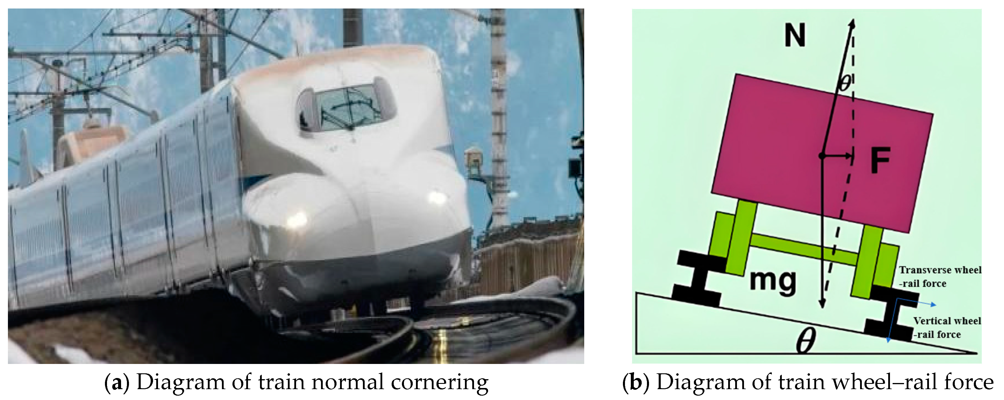
High-speed railways are designed to enhance ride comfort when trains navigate curves. To achieve this, an elevation difference is introduced on the outer rail based on the curve radius. This superelevation counteracts centrifugal forces during train cornering, as illustrated in
Figure 3. The centrifugal force generated during cornering is transmitted through the rails and fasteners to the ballastless track system, manifesting as transverse wheel–rail forces. The transverse wheel–rail forces and the train’s vertical load share the same frequency. However, existing studies on the fatigue performance of ballastless tracks under train loads have largely overlooked the impact of transverse wheel–rail forces. Most fatigue testing methods focus solely on vertical fatigue loads, which differ significantly from the combined fatigue loads experienced by high-speed railway track systems in actual operation.
Existing studies on the fatigue performance of ballastless tracks have primarily focused on the track system as an isolated structure, often simplifying the underlying substructure as a rigid bedding layer. However, in high-speed railway lines, the ballastless track-girder system constitutes the majority of the infrastructure [
3]. Research has also demonstrated significant differences in fatigue performance between track-girder systems and individual ballastless tracks and girders under train fatigue loads [
31,
32,
33]. Zhou et al. [
34,
35,
36], from our research group, investigated the stiffness degradation of a three-span CRTS II-girder system under vertical train loads. However, studies on the CRTS III-girder have placed insufficient emphasis on the bonding performance of door-style reinforcement bars and the influence of transverse wheel–rail forces.
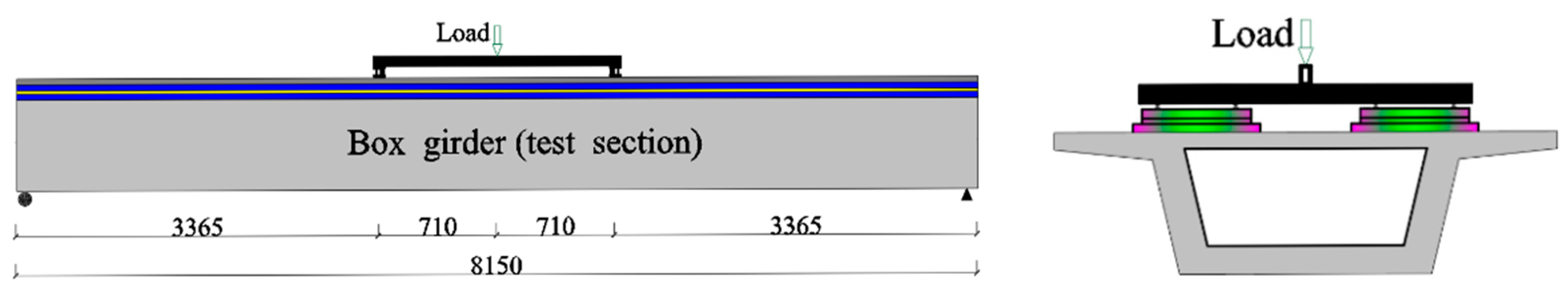
To address the current limitations in fatigue performance studies of CRTS III ballastless track, a 1:4 scale model of a three-span CRTS III ballastless track-girder system was developed in this study. The casting process carefully considered the prestressing of track slabs and the arrangement of embedded door-style reinforcement bars. Fatigue loading simulations were conducted with multi-level variable amplitude lateral and vertical forces at the same frequency, replicating the transverse and vertical wheel–rail forces generated by trains on CRTS III ballastless track during operation. This study addresses the gap in research on the cooperative behavior of the CRTS III ballastless track-girder system under train-induced fatigue loading. The findings confirm that the CRTS III system exhibits strong fatigue performance under train loads. Additionally, the study reveals the stress distribution characteristics of each layer within the ballastless track structure under fatigue conditions. Notably, it identifies a gradual increase in the transverse relative displacement of the sliding layer, which may ultimately impact driving safety. In summary, this research systematically evaluates the fatigue behavior of CRTS III beams through large-scale fatigue testing, uncovering their complex stress evolution. The results provide a crucial experimental foundation for optimizing high-speed railway track system design.
3. Strain Variation Law of Structural System
3.1. Track Slab
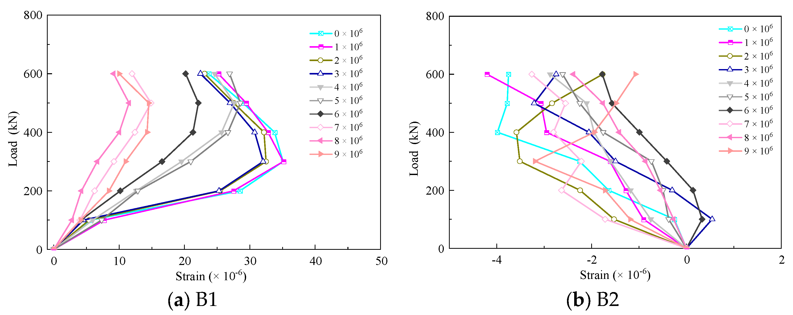
To investigate the degradation pattern of the track slab concrete at the mid-span and support locations under fatigue loading, the strain-load variation of the track slab under static loading after every 1 million cycles of fatigue loading is presented, as shown in
Figure 10.
As shown in
Figure 10a,b, the longitudinal strain of the track slab concrete at both the mid-span and support locations exhibited a nonlinear variation trend. The concrete at the mid-span of the track slab was generally under compression. At the support locations, the maximum compressive strain was only −5.188 × 10
−6. Due to the minimal strain variation and considering the accuracy of the measuring equipment, a detailed analysis was not provided. However, a certain regular pattern in the concrete strain at the support locations could still be observed with the increase of static load. As the static load increased, the strain in the mid-span track slab concrete initially increased and then decreased, indicating a highly complex stress state. The maximum compressive strain of mid-span track slab concrete initially measured −27.9 × 10
−6 under a static load of 500 kN. After 9 million cycles of fatigue loading, when the static load reached 500 kN again, the strain decreased to −10.7 × 10
−6, representing a 61.6% reduction. Due to the presence of geotextile between the base plate and SCC in the CRTS III-girder, which functions as a sliding layer, the track slab and SCC bore the majority of the load during the initial phase of static loading. However, as the static loading progressed, the interlayer space was compressed, resulting in a tighter connection between layers. Consequently, the proportion of the load borne by the base plate and box girder increased. This process facilitated the redistribution of internal stresses within the CRTS III-girder. Ultimately, it resulted in a reduction of stress in the track slab and SCC during subsequent static loading steps.
The strain response of the mid-span track slab concrete under load level 1 exhibited significant differences from the load-strain curves under load level 2 and load level 3. We attribute this phenomenon to the complex vertical multi-layer structure of the CRTS III-girder. Initially, each layer of the structure had various microcracks and voids. Under the action of cyclic loads, these microcracks and voids were repeatedly compressed, leading to the redistribution of internal stresses within the structure. Ultimately, the CRTS III-girder achieved a partial self-optimization effect. Furthermore, the initial fatigue loads caused a closer connection between the layers of the CRTS III-girder. The synergy between the ballastless track-girder also gradually improved. As the number of fatigue load cycles increased, the mid-span concrete strain of the track slab exhibited a consistent directional change.
As shown in
Figure 10c, the mid-span track slab surface concrete strain exhibited nonlinear behavior. The mid-span track slab surface concrete was subjected to transverse tensile forces. Similar to
Figure 10a,b, the strain response under load level 1 differed significantly from the load-strain curves under load level 2 and load level 3. Under load level 1, the tensile strain decreased with the number of load cycles. Under load level 2 and load level 3, the tensile strain response began to increase with the number of load cycles.
3.2. Self-Compacting Concrete Layer
To investigate the deterioration behavior of SCC at the mid-span and support locations under fatigue loading, the strain-load variation of SCC under static loading was measured after every 1 million cycles of fatigue loading. The results are presented in
Figure 11.
As shown in
Figure 11a,b, the longitudinal strain of SCC at both the mid-span and support locations exhibited a nonlinear trend. The SCC concrete at the mid-span was generally in tension. The strain variation at the support locations was minimal and not analyzed in-depth, but it still showed some regular changes. The maximum tensile strain of mid-span SCC concrete initially measured 35.0 × 10
−6 under a static load of 300 kN. After 9 million cycles of fatigue loading, when the static load reached 300 kN again, the strain decreased to 11.0 × 10
−6, representing a 68.6% reduction. With the increase in static load, the strain of the mid-span SCC concrete initially increased and then decreased. This phenomenon occurred because the CRTS III-girder system functioned as a two-layer laminated structure, separated by a geotextile isolation layer. The upper layer consisted of a composite plate formed by the track slab and SCC layer, while the lower layer comprised a composite beam formed by the base plate and box girder. Therefore, the track slab and the SCC layer exhibited a vertical stress distribution. Under static loading, the interlayer space within the CRTS III-girder system contracted, leading to a tighter connection between layers. As a result, a greater proportion of the load was transferred to the base plate and box girder, promoting the redistribution of internal stress within the CRTS III-girder system.
Similarly, the strain response of the SCC concrete at the mid-span under load level 1 showed significant differences compared to the load-strain curves under load level 2 and load level 3. Additionally, as the number of fatigue load cycles increased, the strain of the SCC concrete at the mid-span exhibited consistent directional changes.
Thus, it could be observed that the track slab and SCC can be approximated as a composite slab, working in coordination. Under static loading, the track slab and SCC exhibit a stress characteristic of compression in the upper layer and tension in the lower layer.
3.3. Base Plate
To investigate the deterioration pattern of the base plate concrete at mid-span and support locations under fatigue loading, the strain-load variation of the base plate concrete under static loading is presented after every 1 million cycles of fatigue loading, as shown in
Figure 12.
As shown in
Figure 12a,b, the base plate at mid-span was in a state of compression, with its load-strain curve exhibiting a certain degree of nonlinearity. However, the nonlinearity was significantly reduced compared to the load-strain curves of the track slab and SCC. The concrete strain at the base plate near the supports was relatively small, but still mostly in tension. The minimum compressive strain of the base plate concrete under a 600 kN static load initially measured −155.2 × 10
−6. After 9 million cycles of fatigue loading, when the static load reached 600 kN again, the compressive strain increased to −215.15 × 10
−6, representing a 38.6% increase compared to the initial stage. With the increase in the number of fatigue load cycles, the compressive strain in the mid-span base plate concrete gradually increased. Additionally, under load level 1, the strain variation was more significant. Under load level 2 and load level 3, the strain variation was smaller. The rate of strain change exhibited significant differences between the first and subsequent cyclic loading stages, which is consistent with the behavior observed in the mid-span track slab and SCC concrete.
3.4. Girder
As shown in
Figure 13a,b, the web of the box girder experienced compression at the top and tension at the bottom. The load-strain curve of the concrete at the box girder top exhibited a trend similar to that of the mid-span base plate, displaying a certain degree of nonlinearity. The load-strain curve of the concrete at the box girder bottom, however, showed linear behavior. With the increase in the number of fatigue load cycles, the concrete strain at both the top and bottom of the web gradually increased. The deterioration of the web concrete due to fatigue cycles was evident.
3.5. Structural System
In summary, the CRTS III-girder, being a vertical multilayer structure with varied interlayer connections, exhibited highly complex stress distribution patterns. The stress distribution in the CRTS III-girder can be summarized as follows: Firstly, the track slab and SCC function cooperatively as a composite slab, demonstrating compressive stress at the top and tensile stress at the bottom. Secondly, due to the presence of a sliding layer, initial micro-cracks and voids in CRTS III-girder layers were compressed repeatedly under fatigue loads, leading to an internal stress redistribution. This process facilitated a partial self-optimization effect in the CRTS III-girder. Additionally, the initial fatigue loads tightened the connections between the layers of the CRTS III-girder. Consequently, the synergy between the ballastless track and the box girder also gradually improved. Thirdly, the nonlinearity of the longitudinal load-stress relationship in the CRTS III-girder decreased from the top to the bottom layers. As the number of fatigue load cycles increased, varying degrees of degradation were observed in the concrete at the mid-span layers. Due to the unit nature of CRTS III ballastless track, the sections at the supports were less affected by this loading method. Finally, no significant cracks were observed in the layers of the CRTS III-girder after 9 million fatigue load cycles. This indicated that the performance of the interlayer cooperation under long-term fatigue train loads remained robust.
To further analyze strain variations and change rates in the concrete layers of the CRTS III-girder under cyclic loading, the strain values and change rates in the concrete of each structural layer under a 600 kN static load, with respect to the cyclic load levels, are presented in
Table 5. Due to the relatively small strain values in the concrete at the supports, the analysis below focuses solely on the mid-span section.
As shown in
Table 5, under cyclic loading, the longitudinal strain of the mid-span track slab and the self-compacting concrete layer exhibited an overall decreasing trend, with similar rates of change at −66% and −57.9%, respectively. However, under different loading levels, the variation of longitudinal strain rates between the two was quite different. The transverse strain rate of the track slab surface concrete was 65%, closely matching the longitudinal strain rate of the track slab. The rate of change in concrete strain at the mid-span cross-section of the CRTS III-girder decreased from top to bottom. Based on the strain rate, the CRTS III-girder could be divided into three parts: the track slab and SCC working as a composite structure, the base plate, and the box girder.
4. Interlayer Displacement of the CRTS III-Girder
The interlayer relative displacement of the CRTS III-girder was measured using a high-precision displacement gauge with a range of 20 mm, an accuracy of 0.2% mm FS, and a precision of 0.04 mm. To ensure data accuracy, displacements below 0.04 mm were disregarded. Measurement points were placed between the sides of the track slab, SCC, the base plate, and the top surface of the box girder in the CRTS III-girder. Under 9 million cycles of fatigue loading, the interlayer relative displacement at the measurement points is shown in
Figure 14.
As shown in
Figure 14, among the arranged measurement points, only the vertical relative displacement between the track slab and base plate at mid-span, the transverse displacement between the track slab and box girder, the longitudinal displacement between the track slab and box girder, and the transverse displacement between SCC and the box girder exceeded the precision range of the displacement gauge used. The relative displacements at the remaining measurement points remained below 0.04 mm under 9 million cycles of loading and can be disregarded.
As shown in
Figure 14a, the relative vertical displacement between the track slab and the base plate was negative under static load. This indicated that as the static load increased, the gap between the track slab and the base plate widened. With the increase in the number of fatigue loading cycles, the vertical relative displacement between the two under a static load of 600 kN gradually decreased. This suggested that with the increase in fatigue cycles, the gap between the track slab and the base plate under the same static load gradually reduced. Furthermore, under load level 1, the static load-displacement curve exhibited a complex and nonlinear behavior. As the fatigue loading progressed to load level 2 and load level 3, the static load-displacement curve gradually transitioned to a linear pattern. We infer that, similar to the strain variation trends, the micro-cracks and voids within the CRTS III-girder structure were repeatedly compressed under initial fatigue loading, leading to an internal stress redistribution. Consequently, the CRTS III-girder achieved partial self-optimization effects. Therefore, the collaborative performance of the CRTS III-girder was enhanced during the initial stages of fatigue loading.
As illustrated in
Figure 14b, under the influence of transverse fatigue wheel–rail forces, the relative transverse displacement between the track slab and the box girder exhibited a notable trend under static load. During load level 1, the transverse displacement between the track slab and the box girder was less than 0.04 mm, which can be considered negligible. However, as the number of fatigue cycles increased, their relative transverse displacement increased in the same direction. The maximum transverse displacement reached 0.1 mm.
As shown in
Figure 14c, the development pattern of the relative transverse displacement between SCC and the box girder under static load was similar to that in
Figure 14b. As the number of fatigue cycles increased, the transverse relative displacement between SCC and the box girder continued to increase in the same direction. The maximum transverse relative displacement remained at 0.1 mm. This indicated that the connection between the track slab and SCC was robust under transverse wheel–rail forces. Under 9 million cycles of transverse and vertical fatigue loads, there was no relative sliding or interlayer separation between the track slab and SCC. Considering that the transverse displacement between the base plate and the box girder was negligible, the following conclusions can be drawn. Under combined transverse and vertical cyclic loads, significant transverse relative displacement degradation occurred between the base plate, the track slab, and SCC. This degradation led to the transverse displacement of the rails, affecting driving safety. Therefore, during the operation of the CRTS III-girder, it is necessary to replace the elastic layer between the base plate and SCC promptly.
As shown in
Figure 14d, the relative longitudinal displacement between the track slab and the box girder gradually increased under static load. With the increase in fatigue load cycles, no significant degradation was observed. The maximum relative longitudinal displacement between the track slab and the box girder was 0.09 mm. This indicated that the sliding layer performed well in terms of longitudinal sliding. It is unlikely to sustain damage under 9 million cycles of combined transverse and vertical fatigue loads.
In summary, under 9 million cycles of transverse and vertical fatigue loads, the connection between the base plate and the box girder remained intact, with no relative displacement occurring in the transverse, longitudinal, or vertical directions. The connection between the track slab and SCC also remained stable, with no relative displacement observed in any of the three directions. The sliding layer between SCC and the base plate exhibited initial larger vertical displacement due to stress redistribution, which subsequently decreased. The sliding layer maintained good longitudinal sliding performance and did not show significant degradation under cyclic fatigue loads. However, the transverse relative displacement of the sliding layer increased with the number of load cycles, potentially causing transverse displacement of the rails and compromising operational safety.
5. Conclusions
Through 9 million cycles of multi-level transverse and vertical fatigue tests on the CRTS III-girder, we investigated the degradation patterns of concrete in various layers and the changes in interlayer displacement. The key findings are as follows.
(1) During the 9 million cycles of multi-level transverse and vertical fatigue tests, no visible cracks or interlayer separation were observed on the surface of the CRTS III-girder. Thus, it can be concluded that the CRTS III-girder maintains adequate structural rigidity under transverse wheel–rail forces and train loads during operation, fulfilling operational requirements without significant damage.
(2) During the 9 million cycles of multi-level transverse and vertical fatigue tests, the load-longitudinal strain curves of the CRTS III-girder layers under static loading displayed distinct patterns. The nonlinearity of the load-longitudinal strain curves decreased progressively from the track slab to the box girder, with the most significant nonlinearity observed in the track slab and SCC. In contrast, the concrete at the bottom of the box girder exhibited an almost linear relationship. Overall, the ballastless track section on the girder experienced a complex stress state, while the box girder remained predominantly in a linear elastic state.
(3) The track slab and SCC were treated as a composite slab, working together under load and exhibiting a characteristic stress pattern, with compression on the top and tension on the bottom. During the initial stages of fatigue loading, the CRTS III-girder underwent self-optimization through stress redistribution. This process improved the interlayer connections within the CRTS III-girder, leading to progressively better coordination between the ballastless track and the box girder. As the number of fatigue load cycles increased, varying degrees of deterioration were observed in the concrete layers at mid-span. Under fatigue loading, the longitudinal strain in the mid-span track slab and SCC decreased, with rates of change of −66% and −57.9%, respectively. In contrast, the longitudinal strains in the base plate, top of the box girder, and bottom of the box girder gradually increased, with rates of change of 38.6%, 10.4%, and 12.2%, respectively.
(4) Under 9 million cycles of transverse and vertical fatigue loading, the connection between the base plate and the box girder exhibited excellent performance, with no relative sliding observed in the transverse, vertical, or longitudinal directions. Similarly, the bond between the track slab and the SCC remained intact, with no relative displacement in any direction. The interface between the SCC and the base plate acted as a sliding layer. Initially, due to stress redistribution, the vertical relative displacement at this interface increased before decreasing. The sliding layer demonstrated effective longitudinal sliding performance, with no significant deterioration under cyclic fatigue loading. However, as the cyclic loading progressed, the transverse relative displacement of the sliding layer gradually increased, reaching a maximum of 0.1 mm. This increase in transverse displacement could lead to rail transverse displacement, potentially compromising operational safety.


