1. Introduction
TA18 titanium alloys are widely used in the aerospace, automotive, and shipbuilding industries, among others [
1,
2,
3,
4]. TA18 titanium alloys have higher strength than pure titanium, which exhibits good mechanical properties in different temperature environments and has relatively good processing plasticity and welding properties. TA18 titanium alloy thin-wall tubes with necked and thickened features have commonly been used as high-axial-bearing components, effectively enhancing high-performance capabilities.
However, it is difficult to form titanium alloy parts at room temperature. Many studies have explored the forming process at high temperatures. Paghandeh et al. [
5] studied the flow behavior and microstructural evolution of titanium alloys at different temperatures, and found that increasing temperatures could increase the material’s compressibility. However, significant flow softening was observed in the compression curves at 500 and 600 °C. Yang et al. [
6] proposed a thermal stamping process for titanium alloy plates with a sandwich structure, which improved the temperature distribution and friction conditions in the forming process. At 900 °C, the stamping depth of the formed titanium alloy parts increased to 135.7%, and local thinning decreased. Li et al. [
7] proposed a reliable high-frequency induction heating auxiliary system and found that heating the material to 700 °C significantly reduced the required forming force, while improving the geometric accuracy and thickness distribution. Camberg et al. [
8] demonstrated the fracture index framework of the generalized incremental stress-state-related damage model (GISSMO), which was extended by temperature correlation, and could predict failure under non-isothermal conditions. In addition, Furushima et al. [
9] integrated the conventional die-free stretching process, and found that the torsion limit increased under the condition of water-cooled local heating. Moreover, the combination of local thermal-assisted torsion forming with die-free stretching produced a synergistic effect, which could cause greater torsion deformation while reducing the diameter of the metal tube. Therefore, thermal forming has typically been used for the formation research of normal-temperature refractory materials.
Light and efficient necking and thickening tubes are also difficult to fabricate, with researchers worldwide conducting work on tube necking and thickening formation. Liu et al. [
10] studied the neck deformation of tubes during thermal extrusion using two different heating methods, and the results showed that partial heating could easily improve the deformation of tube necking and avoid tube flexion compared to uniform heating. In addition, Furushima et al. [
11] demonstrated that non-circular microtubules could be formed by the local heating of a Zn-22Al superplastic alloy during die-free stretching. Lu et al. [
12] fabricated Mg-Nd-Zn-Zr microtubules using a double-extrusion process with large plastic deformation. Lu et al. [
13] also found that the thickness of the tube wall gradually increased along the sinking section of the z axis, demonstrating that the appropriate process could increase the thickness of the necked tube end wall. By analyzing the deformation law of the rear bridge under horizontal bidirectional extrusion using theoretical calculations, numerical simulations, and experimental studies, Guo et al. [
14] determined that necking deformation was accompanied by tube wall thickening, and the wall thickness at different positions could be controlled by controlling the distribution of the temperature field. Li et al. [
15,
16] studied 5A02 thin-walled aluminum alloy tube necking and thickening forming using a differential temperature hot extrusion process, and found that higher temperature in the thickening zone is more conducive to fabricating high-quality parts, and the thickness of the tube wall in the thickening zone of the formed parts increased by more than 500%.
In this study, a finite element model was developed to simulate the necking and thickening processes of TA18 titanium alloy thin-walled tubes, with the aim of comparing the effects of differential temperature and isothermal methods on the temperature and wall thickness distributions within the tubes. Experiments on the necking and thickening of TA18 titanium alloy tubes were conducted using both differential temperature and isothermal methods, thereby verifying the findings from the simulation and enhancing the reliability of the study. Furthermore, EBSD testing was performed on TA18 titanium alloy tubes to investigate changes in microstructure.
In contrast to previous studies focusing on single-process improvements or specific alloy applications, this research systematically investigates TA18 titanium alloy thin-walled tube necking and thickening through both finite element modeling and experimental validation. By directly comparing differential temperature and isothermal forming methods, this work uniquely identifies how temperature gradient positioning influences temperature and wall thickness distributions. The integration of numerical simulations with physical experiments provides a comprehensive analysis framework, addressing critical gaps in the existing literature. This novel approach not only advances our fundamental understanding of TA18 titanium alloy formability, but also offers practical guidelines for optimizing industrial manufacturing processes.
2. Principle
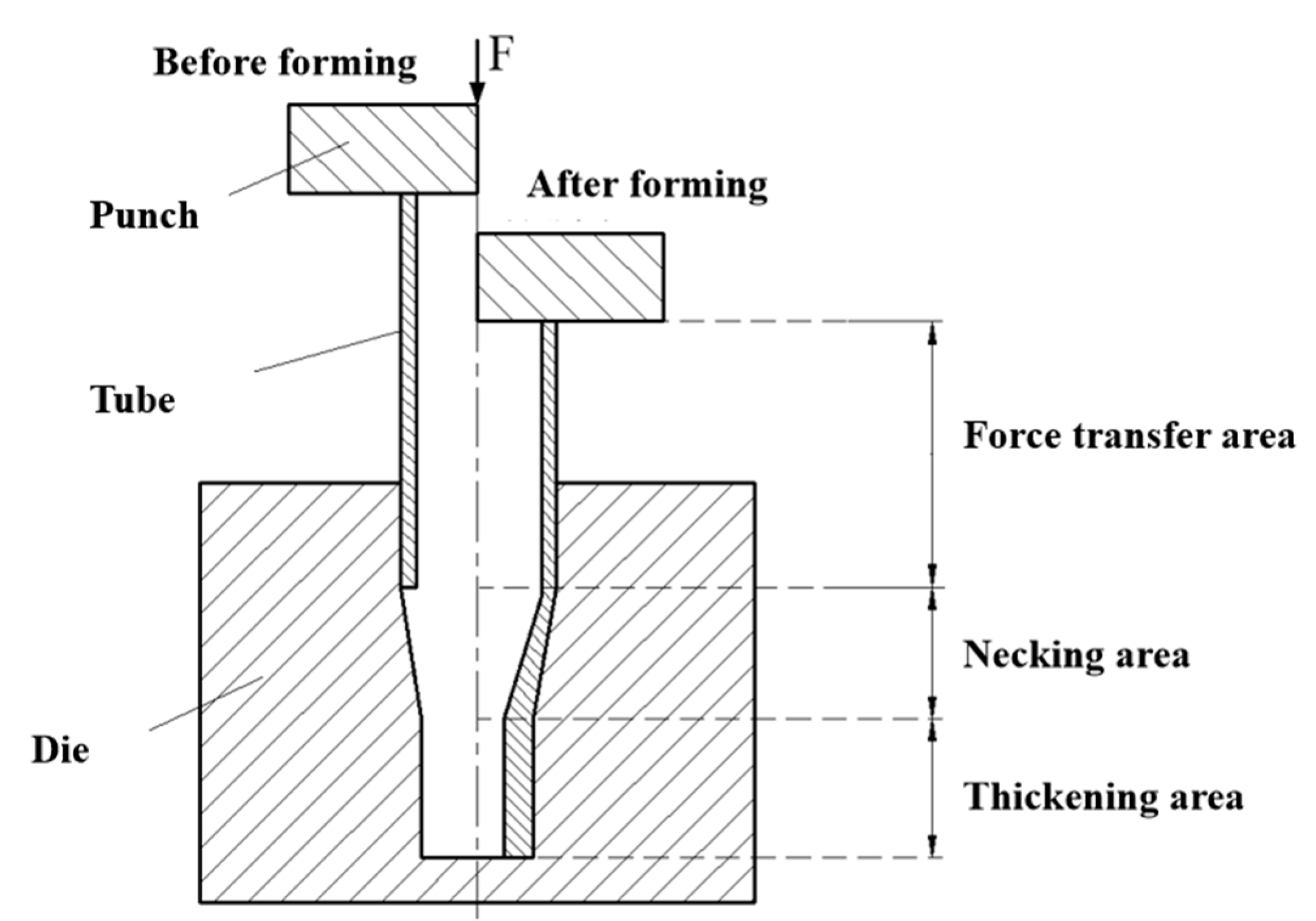
Necked and thickened tubes need to have a thickened end to be further machined, while the other areas need to remain thin to lose weight. The basic principle of the necking and thickening of tubes is shown in
Figure 1. The tube can be divided into a force transfer area, necking area, and thickening area. The force transfer area consists of the area subjected to deformation. Under the action of thrust F applied by a punch, the tube can move forward, causing axial compression and radial deformation. Due to the limitation of the concave die in the necking area, radial pressure in the tube occurs. At this time, the tube begins to neck and continues to move forward with the movement of the punch. When the tube end reaches the bottom of the concave die, the necking-forming stage of the tube is complete. As the punch continues to move forward, the material in the thickening area starts to flow radially, and the wall starts to thicken. The material of the tube constantly flows from the force transfer area to the necking area and the thickening area.
During the necking and thickening process, the stress and strain states vary significantly among the force transfer area, necking area, and thickening area, as depicted in
Figure 2. When the punch applies axial pressure to the tube blank, the material in the force transfer area primarily experiences an axial principal stress σ1. As the process progresses to the necking stage, the tube forms under the influence of both the circumferential stress σ3 and the axial stress σ1.
When entering the thickening area, the tube endures both the axial thrust and the radial support force from the mold cavity surface. Once the front end of the tube reaches the bottom of the cavity in the thickening zone, the axial stress σ1 persists, and the front-end surface exerts an axial counter-support force with the die. With continuous feeding of the punch, the necking area tube surface supplies the radial stress σ2, leading to the material undergoing a dominant strain ε2. Consequently, the material flows radially and accumulates, achieving the objective of thickening the tube’s end.
3. Finite Element Model of TA18 Titanium Alloy Tube Necking and Thickening Forming
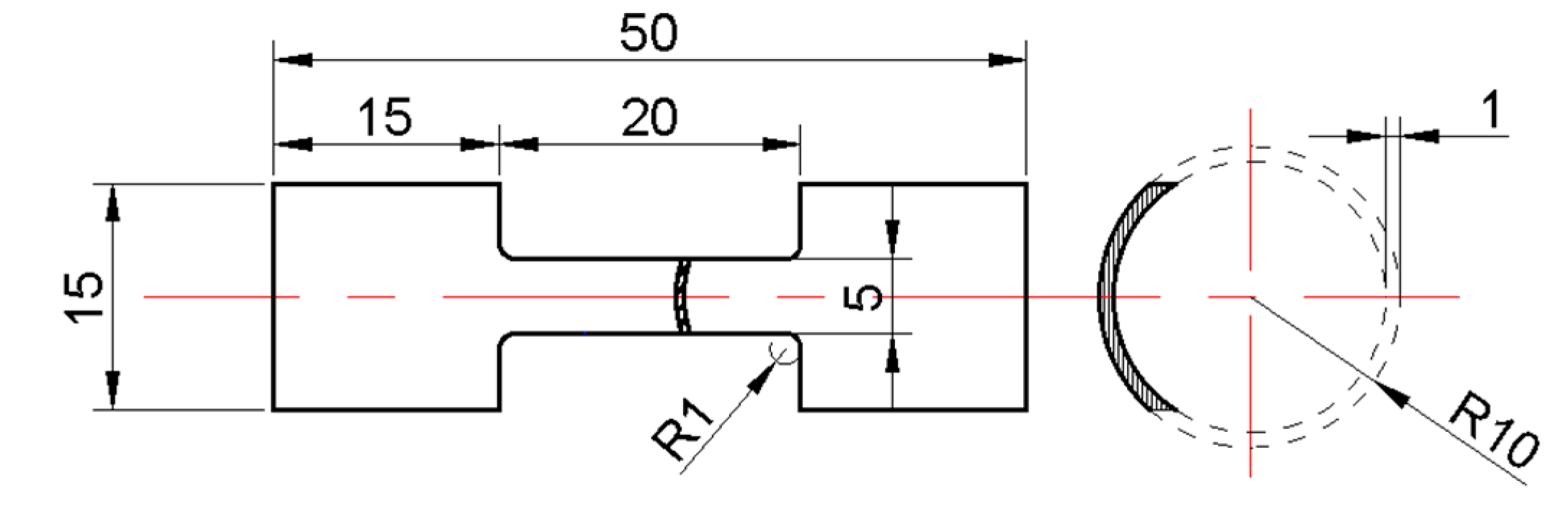
To investigate the mechanical behavior of the TA18 titanium alloy, the shape and size of the tensile specimen are designed, depicted in
Figure 3. tensile specimens were tested at various temperatures: 600, 650, 700, and 750 °C. The resulting true stress–strain curves, depicted in
Figure 4, revealed a significant decline in the flow stress of the material with decreasing temperature and strain rate. The chemical composition of the TA18 titanium alloy is shown in
Table 1.
A finite element model of tube necking and thickening was established using Deform-3D, as shown in
Figure 5. The diameter of the TA18 titanium alloy tube blank was set to 20 mm, the wall thickness was set to 1 mm, the length of the die transfer area was 20 mm, the length of the necking area was 20 mm, the cone angle of the necking area was 16°, the length of the thickening area was 20 mm, the diameter of the thickening area was 16 mm, and the cone angle of the necking area was set to 16°. Due to the symmetry of the geometry of the tube blank and mold, only a quarter model was established. The punch, cooler, and die were set as rigid bodies, while the tube blank was set as a plastic body. By refining the mesh in the deformation area of the tube blank, the minimum mesh size was 0.29 mm, and the total number of mesh elements was 50,952. During the necking and thickening process, the forming temperature in the thickening zone of the concave mold was set to 700 °C, the temperature of the cooler was set to 20 °C, and the coulomb friction model was selected according to the friction type with a friction coefficient of 0.15.
To ensure efficient calculation, only the heat transfer between the mold and the tube billet was considered, while the heat transfer between the tube and the die to the air was not. In the isothermal model, the entire die was set with the forming temperature, which was directly imposed by the tube blank. In the differential temperature model, the thickening area of the die was set with the forming temperature, while the necking area was maintained at 20 °C. So, a temperature gradient was established. The heat transfer temperature of the tube decreased from the thickening area to the necking area, and then to the force transfer area.
4. Analysis of Finite Element Simulation Results of TA18 Titanium Alloy Tube Necking and Thickening
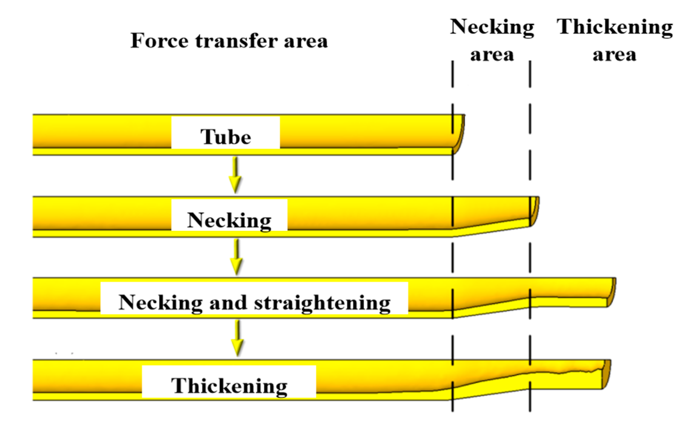
The necking and thickening forming of the titanium alloy thin-walled tube can be divided into three stages, as shown in
Figure 6. The first stage is the necking stage, when the tube is fed into the necking area, and the diameter of the tube material in the necking area gradually decreases along the radial direction, until it reaches the junction between the necking area and the thickening area. The second stage is the straightening stage, when the tube enters the thickening area and the diameter remains constant until the front end reaches the bottom of the die. The third stage is the thickening stage, when the tube’s front end reaches the bottom of the die, and the material accumulates in the thickened area.
4.1. Influence of Isothermal Forming and Differential Temperature Forming on Temperature Distribution
The location of the temperature gradient varies depending on the heating method.
Figure 7 illustrates the tube temperature distribution at each forming stage. It is evident that the isothermal tube exhibits a more uniform temperature in both the necking and thickening areas compared to the differential temperature tube. In all three forming stages, the temperature gradient is located in the force transfer area. The temperature in the necking and thickening areas remains at approximately 700 °C.
It is worth noting that in the isothermal tube, the temperature gradient still lies in the load-transmitting region, while in the differential temperature tube, it shifts to the necking region. During the thickening stage, the temperature in the necking area increases from 320 to 550 °C, while the temperature in the thickening area increases from 550 to 700 °C along the axial direction. Notably, the temperature gradient location on the isothermal tube remains in the force transfer area, whereas it shifts to the necking area of the differential temperature tube.
4.2. Effects of Isothermal Forming and Differential Temperature Forming on Wall Thickness
Figure 8 demonstrates that the differential temperature forming process significantly optimizes the tube wall thickness distribution compared to the isothermal method through temperature gradient control. Numerical simulations indicate that the thickening area of the differential temperature tube exhibits a 20% greater wall thickness, while the necking area shows a 23% thinner wall thickness compared to the isothermal tube. These simulated results closely align with the experimental measurements, validating the effective regulation of material flow behavior by temperature gradients. This phenomenon is attributed to the material’s tendency to flow toward the temperature gradient region and maintain uniform temperature—differential temperature forming directs the material flow toward the thickening area by positioning the temperature gradient in the necking region, resulting in a thicker thickening area and a thinner necking area, thus achieving a more ideal wall thickness distribution than isothermal forming.
5. Experiment of TA18 Titanium Alloy Tube Necking and Thickening Forming
TA18 titanium alloy necking and thickening experiments using differential temperature and isothermal methods were carried out to study the influence of temperature gradient location on the thickness distribution of titanium alloy tubes. The experimental apparatus is shown in
Figure 9 and
Figure 10.
Figure 11 illustrates the experimental results of the necking and thickening tubes derived using the differential temperature and isothermal temperature methods. The major thickening area with the differential temperature method is located at the tube’s thickening area, whereas in the isothermal method, it is found at the tube’s necking area.
We measured the wall thicknesses of these two types of tubes, as shown in
Figure 12. Generally, the differential temperature tube exhibits a significantly larger wall thickness in the thickening area and a much smaller wall thickness in the necking area, rendering it a superior forming method compared to the isothermal forming process. Specifically, in the thickening area, the average wall thickness of the differential temperature tube exceeds that of the isothermal tube by 25%. Conversely, in the necking area, it is 23% thinner. From the wall thickness distribution curve in
Figure 12, it can be seen that the wall thickness distribution of the experimentally formed parts is basically consistent with the wall thickness distribution results of the simulated formed parts.
6. Microstructural Analysis of EBSD in Formed Test Parts
Figure 13 presents the EBSD analysis results of the thickened zone. As shown in the figure, due to the bulging effect in the thickened region, dynamic recrystallization occurs, resulting in significant grain refinement. The recrystallized volume fractions at the center and edge positions are 65.3% and 70.3%, respectively, with an average grain size of approximately 3.7 μm. Due to the radial transfer of the material, the orientation of the grains has changed significantly. The central zone predominantly exhibited a {0001}<011-2> texture component, as shown in
Figure 14a, while the edge region was dominated by a {0001}<-1-232> texture, as shown in
Figure 14b. In addition, due to the higher temperature in the thickening zone, some α-phase transforms into β-phase, resulting in a small amount of β-phase precipitates around the equiaxed α-phase grains, with a volume fraction of 1.6%. By comparing the center and edge positions of the thickened zone, it can be observed that the grain sizes at both positions are similar (
Figure 13a,c), indicating that the microstructure of the thickened zone is relatively uniform after forming.
Figure 15 presents the EBSD analysis results for the necking region. Due to the circumferential necking deformation, the geometric orientation of the grains in the edge region (as shown in
Figure 15c) is significantly deflected compared to the central region (as shown in
Figure 15a). The predominant texture components evolved to {0001}<02-21> in the central region and {0001}<03-34> in the edge zone, as shown in
Figure 16. Grain refinement was notably enhanced in the necking zone, with average grain sizes at the center and edge positions of the necking region being 2.9 μm and 2.7 μm, respectively. Recrystallized grains formed a necklace-like distribution along grain boundaries, with recrystallized volume fractions (~40%) significantly lower than those in the thickened zone. There is a small amount of β-phase in the necking region, with a volume fraction of only 0.2%.
Figure 17 presents the microstructural evolution process. Compared to the original microstructure of the blank, when the material enters the necking zone, dynamic recrystallization occurs under the combined effects of strain and temperature. Due to the relatively lower temperature and smaller strain in the necking zone, the growth of dynamic recrystallization grains is not conducive, resulting in a significant refinement of the grains in the necking region. As the material enters the necking zone, the principal stress generated by the die surface support force, combined with axial stress, causes the tube material to undergo plastic deformation at the tube end, leading to an altered grain orientation in the central and edge regions of the necking zone. From the necking zone to the thickening zone, the increase in strain and temperature promotes the nucleation and growth of dynamic recrystallization, resulting in larger grain sizes and higher recrystallized volume fractions in this region compared to the necking zone. When the material reaches the bottom of the thickening zone, the die surface generates an axial counterforce. As the punch continues to feed, the thickened zone’s die surface exerts principal stress, causing radial strain in the material. This drives radial material flow and accumulation, and the radial transfer of the material induces significant changes in grain orientation. As shown in
Figure 18, a lot of metallography was conducted, and metallography was combined to verify the repeatability of the EBSD test.
7. Conclusions
(1) A finite element model was established to simulate the necking and thickening process of TA18 titanium alloy thin-wall tubes. This model compared the effect of differential temperature and isothermal methods on the temperature and wall thickness distributions of the tubes. For the isothermal tube, the temperature gradient location remained at the force transfer area, whereas for the differential temperature tube, the gradient shifted to the necking area. During the thickening stage, the isothermal tube maintained a uniform temperature of 700 °C, while the temperature of the differential temperature tube increased gradually from 320 to 550 °C in the necking area, and then from 550 to 700 °C in the thickening area, along the axial direction.
(2) Materials tend to flow towards the region of the temperature gradient and remain at uniform temperatures. Consequently, the differential temperature tube exhibits a thicker thickening area and a thinner necking area compared to the isothermal tube. Specifically, in the thickening area, most parts of the differential temperature tube had a greater wall thickness than the isothermal tube. Conversely, in the necking area, the differential temperature tube is substantially thinner than the isothermal tube by approximately 20%.
(3) Experiments on the necking and thickening of TA18 titanium alloy tubes were conducted using both differential temperature and isothermal methods to investigate the impact of temperature gradient location on the thickness distribution of the tubes. The differential temperature method exhibits a significantly larger wall thickness in the thickening area and a much smaller wall thickness in the necking area, making it a superior forming method compared to the isothermal process. Specifically, in the thickening area, the average wall thickness of the differential temperature tube is 25% greater, while in the necking area, it is 23% thinner, compared to the isothermal tube. Furthermore, the major thickening occurs in the thickening area of the differential temperature tube, whereas in the isothermal method, it is observed in the necking area.
(4) Through microstructural analysis of the specimens subjected to gradient temperature forming, dynamic recrystallization occurred in the necking and thickening zones. The grain size in the necking zone was refined compared to that in the thickened zone. This process is effective for grain refinement.
Further research directions include optimizing process parameters such as temperature gradients, friction coefficients, and forming velocities to enhance wall thickness uniformity and material flow efficiency; investigating the relationship between dynamic recrystallization, texture evolution, and mechanical properties like fatigue and corrosion resistance under differential temperature conditions; exploring hybrid forming techniques combining differential temperature processes with incremental or additive manufacturing for complex aerospace components; addressing scalability challenges related to thermal stability and real-time control for mass production; and extending the methodology to other titanium alloys or high-strength materials to validate the universality of temperature gradient positioning principles.
Author Contributions
Conceptualization, J.X. and X.X.; methodology, J.X. and X.X.; software, L.W.; validation, L.W., J.X., F.C. and J.X.; formal analysis, J.N. and F.C.; investigation, J.X. and L.W.; resources, X.X. and J.X. writing—original draft preparation J.X. and J.N.; writing—review and editing, F.C.; visualization J.N.; supervision, L.W.; funding acquisition, X.X. All authors have read and agreed to the published version of the manuscript.
Funding
This research was supported by the National Natural Science Foundation of China with Grant No. 52265052, National Major Science and Technology Projects of China (No. J2019 VII-0014-0154), Natural Science Foundation of Jiangxi, China (No. 20224BAB214050), and Open Research Project Fund, China (P2024-028).
Institutional Review Board Statement
Not applicable.
Informed Consent Statement
Not applicable.
Data Availability Statement
The data will be provided when required.
Conflicts of Interest
The authors declare no conflicts of interest.
References
- Yang, H.; Li, H.; Zhang, Z.; Zhan, M.; Liu, J.; Li, G. Advances and Trends on Tube Bending Forming Technologies. Chin. J. Aeronaut. 2012, 25, 1–12. [Google Scholar] [CrossRef]
- Chokkakula, S.; Shui, T.; Jiang, H.; Yang, J.; Li, X.; He, J.; Shen, L.; Liu, J.; Wang, D.; Suryadevara, N.C.; et al. Genotyping of Mycobacterium leprae for understanding the distribution and transmission of leprosy in endemic provinces of China. Int. J. Infect. Dis. 2020, 98, 6–13. [Google Scholar] [PubMed]
- Miller, M.; Chavez, T.; Dearborn, M.; Tong, E.; Devore, E.; Marloth, R.; Li, Y.J.; Zeng, L.; Ramsey, B.; Mulazimoglu, H.; et al. Effect of Heat Treatments on the Mechanical Properties of Ti-3Al-2.5V Alloy. J. Mater. Eng. Perform. 2015, 24, 3277–3290. [Google Scholar] [CrossRef]
- Jun, F.A.; Liang, C.; Lu, S.Q.; Wang, K.L. Effect of geometrical parameters on forming quality of high-strength TA18 titanium alloy tube in numerical control bending. Trans. Nonferrous Met. Soc. China 2018, 28, 309–318. [Google Scholar]
- Paghandeh, M.; Zarei-Hanzaki, A.; Abedi, H.R.; Vahidshad, Y.; Kawałko, J.; Dietrich, D.; Lampke, T. Compressive/Tensile Deformation Behavior and the Correlated Microstructure Evolution of Ti–6Al–4V Titanium Alloy at Warm Temperatures. J. Mater. Res. Technol. 2021, 10, 1291–1300. [Google Scholar] [CrossRef]
- Yang, X.; Wang, B.; Zhou, J. Numerical and Experimental Study on Formability of TC4 Alloy in a Novel Multi-Layer Sheet Hot Stamping Process. Int. J. Adv. Manuf. Technol. 2020, 110, 1233–1247. [Google Scholar] [CrossRef]
- Li, W.; Attallah, M.M.; Essa, K. Experimental and Numerical Investigations on the Process Quality and Microstructure during Induction Heating Assisted Incremental Forming of Ti-6Al-4V Sheet. J. Mater. Process. Technol. 2022, 299, 117323. [Google Scholar] [CrossRef]
- Camberg, A.A.; Erhart, T.; Tröster, T. A Generalized Stress State and Temperature Dependent Damage Indicator Framework for Ductile Failure Prediction in Heat-Assisted Forming Operations. Materials 2021, 14, 5106. [Google Scholar] [CrossRef] [PubMed]
- Furushima, T.; Mashiwa, N.; Sasaki, K. Locally Heat-Assisted Torsion Forming of Metal Tubes for Improvement of Mechanical Properties Based on Microstructure Control. CIRP Ann. 2020, 69, 261–264. [Google Scholar] [CrossRef]
- Liu, G.H.; Guo, Y.Q.; Jiang, Z. Influence of Heating Models on Necking Deformation during Tube Extrusion Process. Adv. Mater. Res. 2011, 189–193, 1778–1781. [Google Scholar] [CrossRef]
- Furushima, T.; Shirasaki, A.; Manabe, K. Fabrication of Noncircular Multicore Microtubes by Superplastic Dieless Drawing Process. J. Mater. Process. Technol. 2014, 214, 29–35. [Google Scholar] [CrossRef]
- Lu, W.; Yue, R.; Miao, H.; Pei, J.; Huang, H.; Yuan, G. Enhanced Plasticity of Magnesium Alloy Micro-Tubes for Vascular Stents by Double Extrusion with Large Plastic Deformation. Mater. Lett. 2019, 245, 155–157. [Google Scholar] [CrossRef]
- Lu, L.; Tang, Y.; Fang, W.; Cheng, J. Tube Reduction of Miniature Inner Grooved Copper Tubes through Rotary Swaging Process. Trans. Nonferrous Met. Soc. China 2013, 23, 377–384. [Google Scholar] [CrossRef]
- Guo, Y.; Xu, C.; Han, J.; Wang, Z. New Technique of Precision Necking for Long Tubes with Variable Wall Thickness. Front. Mech. Eng. 2020, 15, 622–630. [Google Scholar] [CrossRef]
- Li, X.; Xu, X.; Wei, K.; Fan, Y.; Wei, L.; Qui, Z. Effect of Temperature and Friction on Necking and Thickening for 5A02 Aluminum Alloy Thin-Walled Tube in Differential Temperature Extrusion. Int. J. Adv. Manuf. Technol. 2020, 108, 683–694. [Google Scholar] [CrossRef]
- Li, X.; Xu, X.; Fan, Y.; Luo, M.; Tao, R.; Wu, S.; Wei, L. Local Electrically Assisted Necking and Thickening Technology for 5A02 Aluminum Alloy Tube. Int. J. Adv. Manuf. Technol. 2022, 119, 6017–6028. [Google Scholar] [CrossRef]
Figure 1.
Principle of tube necking and thickening forming.
Figure 1.
Principle of tube necking and thickening forming.
Figure 2.
Stress and strain state of each area.
Figure 2.
Stress and strain state of each area.
Figure 3.
Tensile specimen (unit: mm).
Figure 3.
Tensile specimen (unit: mm).
Figure 4.
True stress–strain curves of TA18 at different temperatures.
Figure 4.
True stress–strain curves of TA18 at different temperatures.
Figure 5.
Finite element model of TA18 titanium alloy tube.
Figure 5.
Finite element model of TA18 titanium alloy tube.
Figure 6.
Necking and thickening forming processes of the tube.
Figure 6.
Necking and thickening forming processes of the tube.
Figure 7.
Temperature distribution of tube necking and thickening. (a) Isothermal forming process. (b) Differential temperature forming process. The arrows point to represent the next forming stage.
Figure 7.
Temperature distribution of tube necking and thickening. (a) Isothermal forming process. (b) Differential temperature forming process. The arrows point to represent the next forming stage.
Figure 8.
Wall thickness distribution of the isothermal and differential temperature tubes. (a) Isothermal forming. (b) Differential temperature forming. (c) Wall thickness distribution. A-B is the thickening area, B-C is the necking area, and C-D is the force transfer area.
Figure 8.
Wall thickness distribution of the isothermal and differential temperature tubes. (a) Isothermal forming. (b) Differential temperature forming. (c) Wall thickness distribution. A-B is the thickening area, B-C is the necking area, and C-D is the force transfer area.
Figure 9.
Isothermal experimental equipment. (a) Isothermal equipment. (b) Isothermal die and its heating furnace.
Figure 9.
Isothermal experimental equipment. (a) Isothermal equipment. (b) Isothermal die and its heating furnace.
Figure 10.
Differential temperature experimental equipment.
Figure 10.
Differential temperature experimental equipment.
Figure 11.
Parts of isothermal and differential temperature forming experiments. The red box is the main thickened area.
Figure 11.
Parts of isothermal and differential temperature forming experiments. The red box is the main thickened area.
Figure 12.
Comparison of wall thickness between simulated and experimental formed parts. A–B is the thickening area, B–C is the necking area, and C–D is the force transfer area.
Figure 12.
Comparison of wall thickness between simulated and experimental formed parts. A–B is the thickening area, B–C is the necking area, and C–D is the force transfer area.
Figure 13.
EBSD (Electron Back Scatter Diffraction) characterization of the thickened zone: (a) grain orientation map of the central region; (b) phase distribution map of the central region; (c) grain orientation map of the edge region; (d) phase distribution map of the edge region. (光栅: Grating, 步长尺寸: Step size).
Figure 14.
α-Phase pole figures of the thickened zone: (a) central region; (b) edge region.
Figure 14.
α-Phase pole figures of the thickened zone: (a) central region; (b) edge region.
Figure 15.
EBSD (Electron Back Scatter Diffraction) characterization of the necking region: (a) grain orientation map of the central region; (b) phase distribution map of the central region; (c) grain orientation map of the edge region; (d) phase distribution map of the edge region. (光栅: Grating, 步长尺寸: Step size).
Figure 16.
α-Phase pole figures of the necking region: (a) central region; (b) edge region.
Figure 16.
α-Phase pole figures of the necking region: (a) central region; (b) edge region.
Figure 17.
Microstructural evolution process. (光栅: Grating, 步长尺寸: Step size).
Figure 17.
Microstructural evolution process. (光栅: Grating, 步长尺寸: Step size).
Figure 18.
Microstructural evolution process.
Figure 18.
Microstructural evolution process.
Table 1.
Chemical composition (wt%) of the TA18 titanium alloy.
Table 1.
Chemical composition (wt%) of the TA18 titanium alloy.
| Element | C | N | H | O | Al | V | Fe | Ti |
|---|
| Content | 0.08 | 0.05 | 0.015 | 0.12 | 2.0~3.5 | 1.5~3.0 | 0.25 | Allowance |
| Disclaimer/Publisher’s Note: The statements, opinions and data contained in all publications are solely those of the individual author(s) and contributor(s) and not of MDPI and/or the editor(s). MDPI and/or the editor(s) disclaim responsibility for any injury to people or property resulting from any ideas, methods, instructions or products referred to in the content. |
© 2025 by the authors. Licensee MDPI, Basel, Switzerland. This article is an open access article distributed under the terms and conditions of the Creative Commons Attribution (CC BY) license (https://creativecommons.org/licenses/by/4.0/).


