Article

A CNC-Modified PAN Separator Improving the Cycle Stability of Lithium-Ion Batteries

1
Key Laboratory of New Processing Technology for Nonferrous Metal & Materials, Ministry of Education, Guangxi Key Laboratory of Optical and Electronic Materials and Devices, College of Material Science and Engineering, Guilin University of Technology, Guilin 541004, China
2
Key Laboratory of Function-Oriented Porous Materials, College of Chemistry and Chemical Engineering, Luoyang Normal University, Luoyang 471934, China
*
Authors to whom correspondence should be addressed.
Coatings 2025, 15(3), 351; https://doi.org/10.3390/coatings15030351
Submission received: 21 February 2025 / Revised: 8 March 2025 / Accepted: 17 March 2025 / Published: 19 March 2025

Abstract

:
In this paper, a composite separator for lithium-ion batteries was successfully prepared by electrostatic spinning, based on polyacrylonitrile (PAN) and 5% cellulose nanocrystals (CNCs) derived from sisal fiber. Its physical and electrochemical properties as well as the enhanced mechanism were investigated. The obtained 5%CNCs/PAN separator offers an excellent thermal stability, ultra-high electrolyte uptake (486 ± 30%), high ionic conductivity (2.82 mS cm−1 at 25 °C) and a wide electrochemical window (5.3 V). In addition, a lithium-ion battery assembled with the 5%CNCs/PAN separator can work stably for 1000 h at 5 mA cm−2. The CNCs in the electrolyte enable the immobilization of PF6, thereby inhibiting the migration of anions and increasing its Li+ transfer number (tLi+) to 0.75, which is 65.3% higher than that of a pure PAN separator. The battery with the 5%CNCs/PAN separator retains 97.4% of its initial reversible capacity after 100 cycles, which is much higher than that of a pure PAN separator, with a value of 62.9%. These results suggest the potential utility of 5%CNCs/PAN separators as high-performance separators required in lithium-ion batteries.

1. Introduction

Lithium-ion batteries (LIBs), characterized by high energy density and extended cycle life, have become ubiquitous in modern energy systems, powering portable electronics, propelling electric vehicles (EVs), and enabling efficient grid-scale energy storage solutions critical for decarbonizing contemporary infrastructure [1,2]. Therefore, the development of low-cost, environmentally friendly lithium-ion batteries is critical to the long-term viability of large-scale renewable energy consumption [3,4]. The separator, as a fundamental component of the battery, has a substantial impact on the battery’s safety, lifetime, and electrochemical performance, all of which are critical for the energy storage system’s long-term sustainability. On the one hand, the separator serves as an electrical barrier between the positive and negative electrodes, preventing internal short circuits [5,6,7]. This requires insulating qualities and high mechanical strength and electrochemical and thermal stability. The separator, on the other hand, acts as a route for lithium ions to migrate between the two electrodes, necessitating high lithium-ion conductivity in the liquid electrolyte [6,8,9]. The separator is a crucial component of lithium-ion batteries that influences the battery’s electrochemical performance. Commercial lithium-ion battery separators have low electrochemical performance, which limits their application in electric vehicles and energy storage systems [10,11,12]. Polypropylene (PP) and polyethylene (PE) have long been used as commercial separator materials. Polyolefin-based separators have limited porosity, considerable thermal shrinkage, and low thermal stability, resulting in poor electrochemical properties [13,14]. To address these issues, various types of polymer separators and separator production procedures have been employed. The electrostatic spinning technique has garnered a lot of attention in recent years, allowing for the development of novel separator materials with high porosity, specific surface area, electrolyte absorption, and ionic conductivity [15,16,17].
The separators prepared by the electrostatic spinning process have been observed to exhibit a three-dimensional structure and high porosity and ionic conductivity, which renders them ideal candidates for use in the preparation of lithium-ion battery separators [18,19]. The main polymer materials employed for the production of electrostatically spun fiber barrier separators at this stage include polyvinylidene fluoride (PVDF) [20,21], polyacrylonitrile (PAN) [22,23,24,25,26,27], and polymethylmethacrylate (PMMA) [28], etc. PAN has a cyano group (-CN) which can interact with the carboxyl group of the electrolyte component, thereby enhancing the compatibility of PAN with the electrolyte [29,30,31]. Concurrently, PAN exhibits optimal spinnability in electrostatic spinning technology. The porosity of lithium-ion battery separators is typically constrained to a certain range, as excessive porosity will impair the self-closing properties of the battery and compromise the mechanical strength of the diaphragm, and it will also affect the ion transfer [11,32,33,34]. Conversely, insufficient porosity will result in inadequate electrolyte filling, which is necessary for optimal battery performance. The porosity of polyolefin diaphragms which are commercially available is typically within the range of 40% to 50% [35]. Fiber diaphragms obtained through electrostatic spinning exhibit a higher degree of porosity, reaching 80% or even higher [36,37]. Consequently, electrostatically spun diaphragms demonstrate superior ionic conductivity, which can significantly diminish battery impedance and enhance battery performance. However, the electrostatic spinning process allows the jet to be cured in a relatively short period of time, which reduces the stretching effect on the fiber molding process and consequently lowers the separator’s crystallinity, resulting in a relatively poor mechanical property. Concurrently, diaphragms manufactured via electrostatic spinning exhibit a substantial pore size and an irregular pore size distribution. These characteristics facilitate the penetration of lithium dendrites into the diaphragm, thereby increasing the likelihood of short-circuits within the battery during operation [31]. On the other hand, the current distribution through the diaphragm become unstable when the battery is operational, resulting in a local current that is excessive and detrimental to the battery’s performance [38]. To address this issue, a variety of particles are employed as fillers in the preparation of lithium battery diaphragms. Yang et al. [39]. prepared a MOF/PAN composite diaphragm by spinning MOF as a filler with PAN. The resulting composite exhibited enhanced mechanical properties and more stable electrochemical properties compared to the PAN separator. Tang et al. [40] employed a two-step hydrolysis process using tertbutyl titanate and isopropyl titanate as titanium source precursors, with the addition of acrylic acid facilitating the generation of TiO2 and the in situ growth of TiO2 on the PAN separators. The resulting composite separators exhibited discharge capacities of 107.72 mAh/g and 115.79 mAh/g, respectively, under a 2 C discharge condition, with a superior capacity retention rate compared to Celgard2400 (Guangdong Canrd New Energy Technology Co., Ltd., Dongguan, China).
Inorganic nanoparticles are typically produced through complex preparation processes which contribute to their elevated cost of production. Furthermore, a cost structure analysis of LIBs indicates that separators—critical components occupying 10%–15% of total cell production costs—incur substantial manufacturing expenses from energy-intensive processes like dry/wet stretching, thereby elevating commercial battery prices and impeding cost-competitive energy storage deployment. Addressing separator cost reduction challenges, Silvia et al. demonstrated a dual-functional strategy utilizing polyvinyl butyral (PVB)—a glass industry waste stream—as precursor material for lithium-ion battery separators via non-solvent induced phase separation (NIPS). This approach achieved cost reduction compared to conventional polyethylene separators while simultaneously valorizing industrial byproducts [41]. As demonstrated in the preceding analysis, cellulose nanocrystals (CNCs) were identified as a primary raw material for the fabrication of lithium battery diaphragms in this study.
CNCs are a potentially biodegradable structural nanomaterial. CNCs have the advantages of low costs, a wide range of sources, and more stable physical and chemical properties. CNCs possess high crystallinity and an outstanding elasticity modulus, which mean they can effectively regulate the pore size of polyacrylonitrile-based separators and be adjusted to achieve greater uniformity [42,43,44]. Additionally, CNCs can be incorporated into the three-dimensional structures of polyacrylonitrile-based separators, thereby enhancing their mechanical properties, which are currently relatively deficient. The presence of hydroxyl groups in CNCs renders them more compatible with electrolytes, thereby making CNCs a potential raw material for the preparation of high-performance separators [45,46,47]. Sisal (Agave sisalana) is a substantial, perennial cannabis cash crop. Its environmental adaptability, short growth cycle, low price, and other characteristics make it a key resource for a sustainable bio-economy. This is of strategic significance to the reduction in fossil resources and the promotion of green industrial transformation. Due to its high fiber content, sisal is considered a good source of fiber. The versatile sisal cellulose nano whiskers would be particularly useful for applications in nanocomposites as a reinforcing phase. CNCs with biocompatibility and renewable and sustainable properties have attracted particular attention and become an advanced raw material which has been widely investigated in the electrochemical field. The hydrolysis of sisal cellulose with phosphoric acid is safer than sulphonic acid in experimental procedures. Concurrently, CNCs exhibit a more uniform particle size, rendering them more suitable as a reinforcing phase.
Throughout the field, a CNCs and PAN composite separator produced by electrostatic spinning for lithium-ion batteries has not been reported. In this study, we employed a hydrolysis process using phosphoric acid to produce CNCs, which used sisal as a raw material, of consistent size. Subsequently, these CNCs were used in conjunction with PAN in the electrostatic spinning process to create a composite separator with potential applications in lithium-ion batteries. A comprehensive analysis was conducted on the surface structure, mechanical strength, thermal resistance, and electrochemical behavior of CNCs/PAN composite separators containing varying concentrations of CNCs. Additionally, the feasibility of employing these separators in LlBs was successfully validated.

2. Experimental Section

2.1. Materials

Sisal fiber was provided by the Guangxi Sisal Group (Guigang, China). Polyacrylonitrile (PAN, Mw = 85,000) was purchased from Macklin Biochemical Co., Ltd. (Shanghai, China). N,N-dimethylformamide (DMF, AR) and n-butanol (AR) were purchased from Tianjin Deen Chemical Reagent Co., Ltd. (Tianjin, China). N-methyl pyrrolidone (NMP, 99.5%, AR) was purchased from Shanghai Rawn Chemical Reagent Technology Co., Ltd. (Shanghai, China). LiFePO4, Super-P, Polyvinylidene fluoride (PVDF), and the EC/DMC/DEC-based electrolyte (1 M LiPF6, 1:1:1 wt%) were sourced from Guangdong Canrd New Energy Technology Co., Ltd. (Dongguan, China) Our commercial PP separator, Celgard 2500, was purchased from Guangdong Canrd New Energy Technology Co., Ltd. (Dongguan, China).

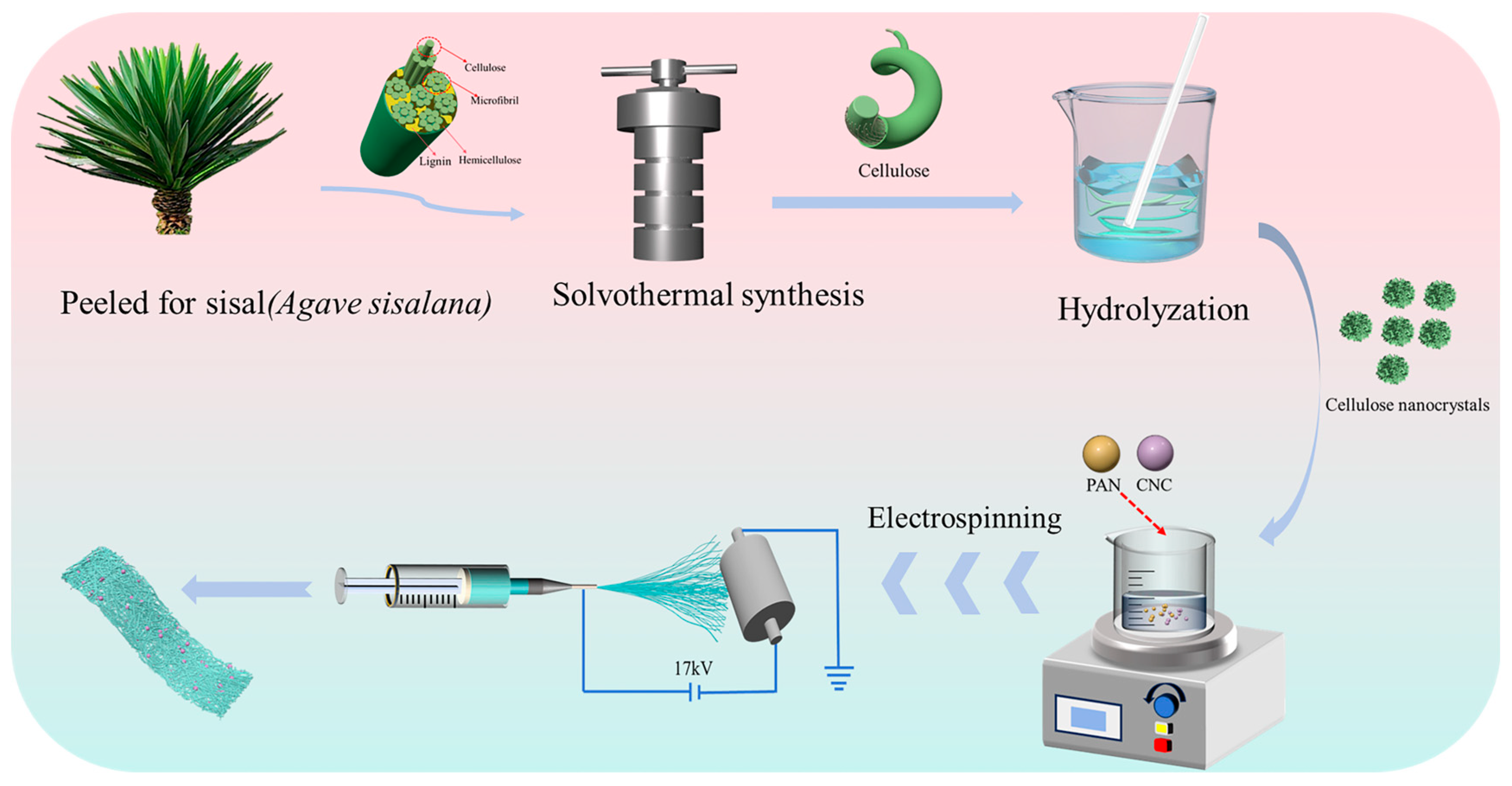
2.2. Preparation of Cellulose Nanocrystals

The sisal fibers were hydrothermally treated with 2.5 M KOH (160 °C,14 h) in a Teflon autoclave. Post-reaction filtration yielded a solid residue, which was washed with deionized water until a neutral filtrate pH was achieved. The ionic conductivity of deionized water is 1.2 μS/cm. It then was dried to a constant weight in order to obtain sisal cellulose. Subsequently, the sisal cellulose was subjected to bleaching with sodium chlorite and acetic acid (mass ratio of 1.5:1). The resulting product was filtered, washed repeatedly until the filtrate was neutral, and subsequently dried, thereby obtaining the final product, sisal cellulose microfiber. The obtained sisal cellulose microfibrils were subsequently subjected to hydrolysis with phosphoric acid, followed by neutralization with ammonia, then centrifuged, and the resulting material was freeze-dried to obtain phosphoric acid-hydrolyzed cellulose nanocrystals. Figure S1 shows their microscopic morphology, and the average particle size of CNCs was calculated to be 200 nm.

2.3. Preparation of CNCs/PAN Separator by Electrostatic Spinning

An appropriate quantity of CNCs was uniformly dispersed in a solution of DMF and then subjected to ultrasonication for 2 h. Subsequently, PAN was added to the resulting solution, which was then stirred at room temperature for 12 h to form a spinning solution. The resulting spinning solution was spun at a humidity of 28~35°, and the electrospinning system was configured with the following operational parameters: an applied voltage of 17 kV, a precursor solution infusion rate of 0.001 mL/min, and a collector roller rotating at 30 rpm. The needle-to-collector distance (NCD) between the syringe tip and the aluminum foil-coated roller was fixed precisely at 15 cm. Electrostatic spinning was performed for 12 h to obtain a spun separator, as illustrated in Figure 1. The obtained diaphragm was cut into a circular lithium cell separator with a diameter of 16 mm. Thereafter, the separator was torn off from the aluminum foil. Finally, the separator was compacted by a press to obtain the CNCs/PAN composite separator for the LIBs. According to the different mass additions of CNCs, the composite separators were named 1%CNCs/PAN, 3%CNCs/PAN, 5%CNCs/PAN, 7%CNCs/PAN, and 10%CNCs/PAN, respectively.

2.4. Battery Assembly

For the preparation of the cathode material, the components of LiFePO4, Super-P, and PVDF were combined in an 8:1:1 mass ratio, followed by the gradual addition of NMP grinding. Subsequently, the blended suspension was coated onto aluminum foil and subjected to vacuum drying at 100 °C for a duration of 10 h. The battery was assembled in a glove box filled with argon gas with oxygen and water levels below 0.01 ppm. The separator, cathode material, and lithium wafers were assembled to form a CR2032 model button half-cell. The amount of electrolyte used to assemble the battery was 0.21 mL.

2.5. Characterization

The surface micro-morphology was analyzed using a field emission scanning electron microscope (FE-SEM) manufactured by Hitachi, Tokyo, Japan High-Technologies Corporation, model S-4800. The infrared spectra of the polymers were determined using Fourier Transform Infrared (FTIR) spectrometer model Nicolet iS20, manufactured by Thermon Fisher from Waltham, MA, USA. The complexation of the CNCs with the polymers was subjected to analysis using a D8 ADVANCE-type X-ray diffractometer from Bruker, Bellerica, MA, USA. The voltage was set to 40 kV, the current to 30 mA, the target was Cu, the X-ray wavelength was 1.54056 Å, the scanning range (2θ) was 5 ° to 80 °, and the scanning speed was 5 ° per minute. The thermal properties of the diaphragm were evaluated by a TGA Q500 thermogravimetric analyzer from TA, Inc., Milford, MA, USA. The test conditions were as follows: at room temperature, nitrogen was introduced as a protective gas and heated to 800 °C at a temperature increase rate of 10 °C/min. The thermal stability of the separators was evaluated by means of a quantitative analysis of the onset of decomposition temperature, as observed in the TG curve. Thermal dimensional stability tests were conducted to evaluate the ability of the materials to maintain their shape and dimensions when subjected to elevated temperatures. The thermal dimensional stability of the separators was evaluated through the measurement of the area change in a standard 16 mm button cell separator. The test conditions were as follows: separators were placed in a blast drying oven at temperatures of 120 °C, 140 °C, 160 °C, 180 °C, and 200 °C for a period of 30 min each, and the dimensional changes in the separators are observed. The separator mechanical properties were assessed via tensile tests using a UTM5017 universal testing machine (Shenzhen Sansi Zong Heng, Shenzhen, China). The dimensions of the separators were as follows: 1 cm × 5 cm, and the tensile speed was 5 mm/min. The samples to be tested were cut into 16 mm circular separators, and the contact angle was determined using an optical contact angle meter. The reagent employed for the test was LiPF6 electrolyte. Cutting the separator samples to be tested into 16 mm disks, soaking them in butanol solvent for 1 h at room temperature, then wiping the excess liquid on the surface with filter paper, we measured the mass of the samples before and after soaking using an analytical balance and then calculated the porosity of the separator according to Equation (1) as P (%) [48]:
P = W 1 W 0 ρ b × V 0 × 100 %
where W1 is the mass of the separator after soaking for 1 h; W0 is the mass of the separator before soaking; ρb is the density of butanol; and V0 is the apparent volume of the separator before soaking. The electrolyte uptake of the separators was estimated by the classical weighing method by immersing the separators dried at 60 °C for 12 h in LiPF6 electrolyte for 2 h and using an analytical balance for the mass of the separators before and after immersion in the electrolyte. The liquid absorption rate ΔW was calculated according to Equation (2) [48]:
W ( % ) = W 2 W 1 W 1 × 100 %
where W1 is the mass of the separator after 2 h immersion and W1 is the mass of the dried separator.
A standard LiFePO4/Li coin cell of type CR2032 was assembled with LiFePO4 as the cathode material, a lithium flake as the anode material, and the separators to be tested. The cell was subjected to constant-current charging and discharging cycling tests and multiplication rate performance tests at voltages of 2.5~4.2 V. The Shenzhen Xin Wei cell testing system was employed to assess the cycling performance of the cells through the execution of 100 charge–discharge cycles at a current density of 0.2 C (1 C = 1 A·g−1). The rate capabilities of the cells incorporating different separators were assessed by performing charge–discharge cycling on coin-type cells across different current densities (0.05 C, 0.1 C, 0.2 C, 0.3 C, 0.5 C, 1 C, and 2 C). A LiFePO4 || separator || Li coin cell was assembled to be tested via electrochemical impedance spectroscopy (EIS). The interfacial resistance between the separator and the lithium metal was then investigated after wetting by the electrolyte. The test was carried out using a Shanghai Chen Hua chi760e electrochemical workstation (Shanghai, China) at a frequency range from 0.01–105 Hz, with the amplitude set to 5 mV. The electrolyte-saturated separators were sandwiched between a stainless-steel (SS) sheet and a lithium metal sheet, and measured to obtain the value of the electrochemical window by a linear sweep voltammetry (LSV) method at the electrochemical workstation from the open-circuit voltage to 6 V with a scan rage of 5 mV s−1. The ionic conductivity of the separator was determined by EIS as follows: a sample of the separator to be tested was fully immersed in the electrolyte and positioned between two symmetrical stainless-steel spacers (SS), assembled as a SS||separator||SS coin cell. The test range was 0.01–105 Hz, with an amplitude setting of 5 mV. The ionic conductivity, σ, was calculated according to Equation (3) [49]:
σ = d R 0 × S
where d is the thickness of the separator, R0 is the volume resistance of the separator and the electrolyte system, and S is the surface area of the separator and the electrolyte system. A Li||separator||Li coin cell was assembled by sandwiching a separator soaked in electrolyte between two lithium metals. The interfacial resistance between the separator and the lithium metal was then investigated after the electrolyte was wetted in the frequency range of 0.01–105 Hz. Furthermore, the lithium mobility number (tLi+) was evaluated through the chronoamperometry test method, with the resulting value calculated using the following Equation (4) [48]:
t L i + = I s I 0 × Δ V I 0 R 0 Δ V I S R S
where I0 is the initial current, IS is the steady-state current, R0 is the interfacial resistance before polarization, and RS is the interfacial resistance after polarization. The constant-current cycling experiments were carried out at 25 °C using a Shanghai Chen Hua chi760e electrochemical workstation. For Li||separator||Li symmetrical batteries, the batteries were subjected to a constant current density of j = 0.5 mA cm−2 during the charging phase, which was conducted for a duration of two hours. This was followed by a simultaneous discharge phase, and the battery was discharged/charging for 0.5 h at a constant current density of j = 2 mA cm−2. The potential of the lithium working electrode was detected by the Li/Li+ reference electrode.

3. Results and Discussion

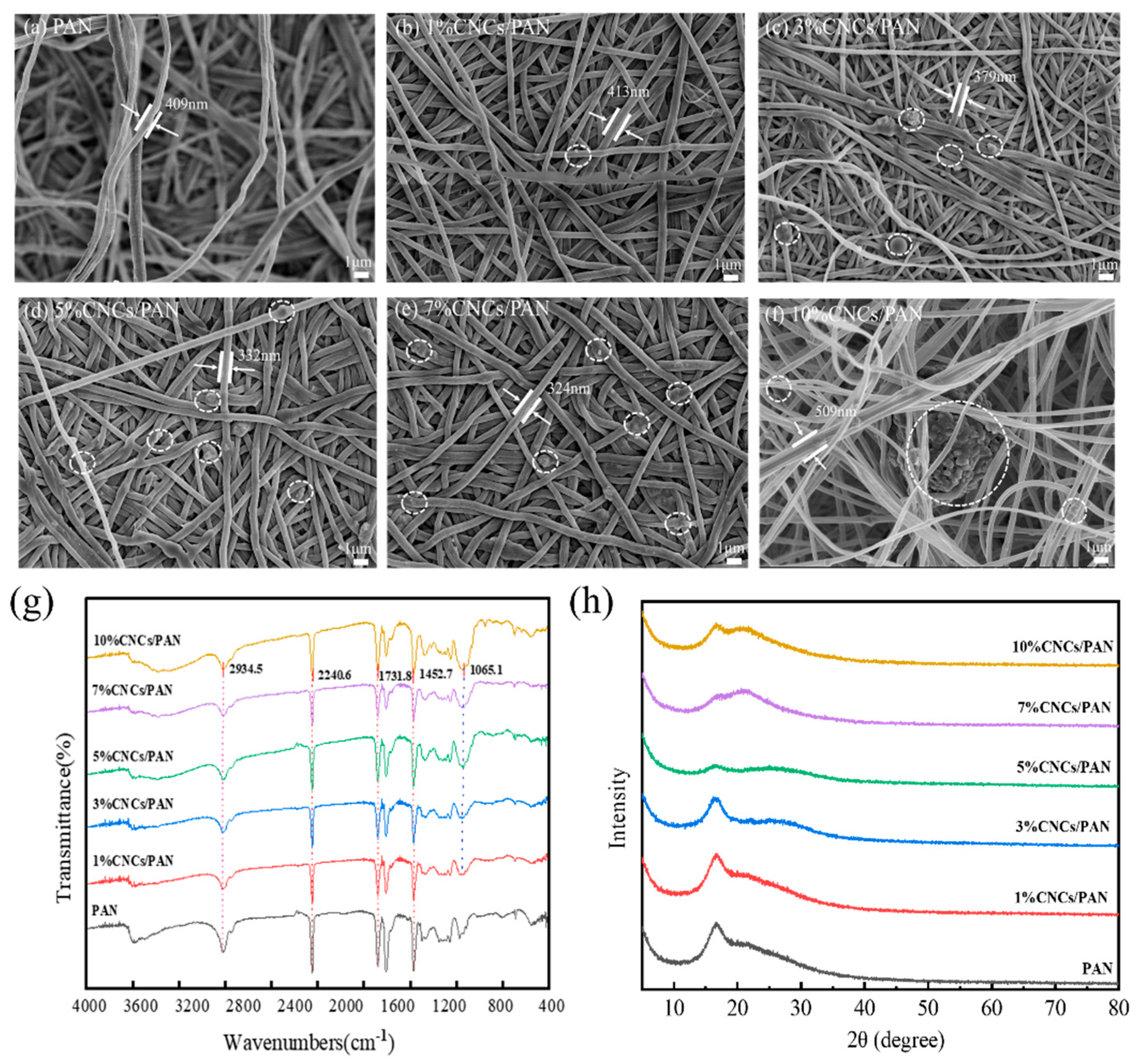
3.1. Microscopic Morphologies and Structures of Separators

To observe the effect of the CNCs on the microscopic morphology of the PAN separator, it was characterized by FE-SEM. The pure PAN separator depicted in Figure 2a exhibits a structural morphology characterized by uninterrupted nanofibers arranged in stochastic alignment, where the interwoven fiber matrix creates a three-dimensional porous architecture through systematically staggered pore–channel interconnections. However, in Figure 2b–f, the CNCs in the PAN composite separators are observed to be attached to the surface of the fibers and embedded in the pores between the fibers. Yet, the presence of the CNCs is not discernible due to the minimal incorporation of the CNCs in the 1%CNCs/PAN composite separator. The additions of CNCs at concentrations of 3%, 5%, and 7% lead to the formation of an interconnected mesh structure and a more uniform fiber diameter in the composite separators. When CNCs were added at concentrations of 10%, this resulted in the filaments becoming knotted and twisted together. This may be attributed to the agglomeration of excessive amounts of CNCs. The high viscosity of the spinning liquid means it is very difficult to split into fibers. To ascertain whether the CNCs affected the molecular structure of the PAN, infrared spectroscopy was employed to analyze the material, as shown in Figure 2g. The spikes are attributed to ν(CHx) at 2934, ν(C≡N) at 2240, and δ(CHx) at 1452, respectively, which are the characteristic absorption bands of PAN [50]. The CNCs/PAN composite separators display an additional band at 1065.1 cm−1, which is attributed to the bending vibration of the -OH bond of cellulose. The greater the number of -OH bonds, the sharper the shape of the band. This observation indicates that the CNCs are combined with PAN. To further demonstrate the success of the CNC composite with PAN, the diaphragms were characterized by XRD. The distinctive peaks associated with the cellulose nanocrystals are not readily discernible in the 1%CNCs/PAN composite separator due to the relatively low concentration of CNCs. As can be seen from Figure 2h, the diffraction peak at 17.01° corresponds to the (100) crystal plane of PAN. The peak intensity of PAN decreases gradually with the increase in the amount of CNCs, which is due to the fact that the addition of CNCs can result in a reduction in the crystallinity of PAN. Furthermore, PAN is in a semi-crystalline state at room temperature. Additionally, due to the low amount of CNCs, the 1%CNCs/PAN and 3%CNCs/PAN separators’ characteristic peak of cellulose is not prominent. The cellulose peak begins to emerge at 22.78 ° at concentrations of 5%, 7%, and 10% CNCs, indicating that those CNCs have been successfully incorporated into the PAN separator.

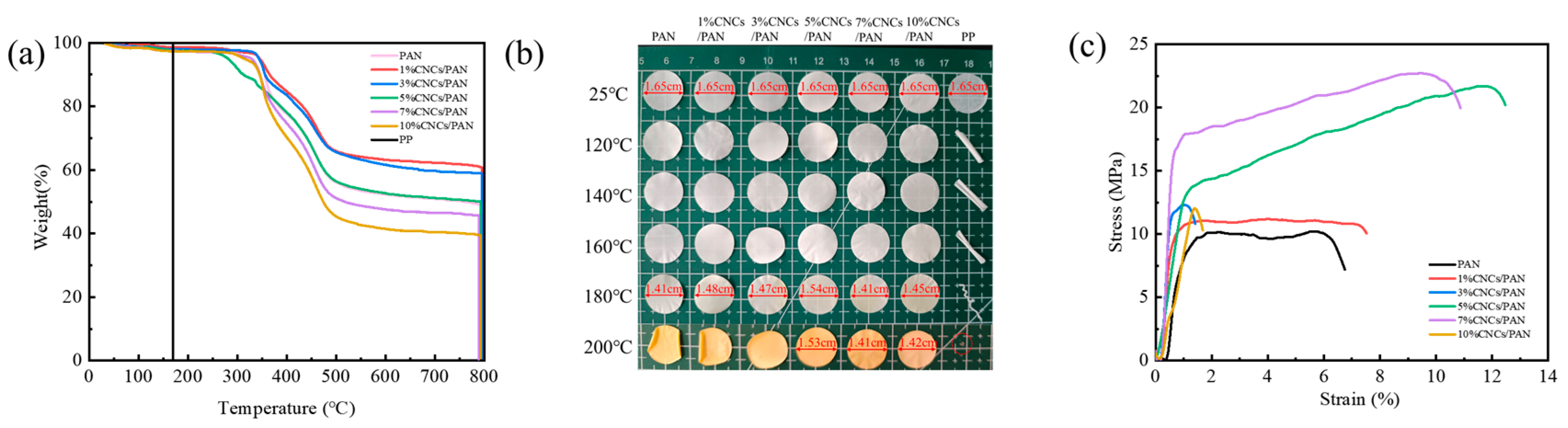
3.2. Thermal Properties of CNCs/PAN Composite Separators

Thermal stability serves as a key safety indicator for lithium-ion battery separators, especially under high-rate cycling conditions. PP, PAN, and CNCs/PAN composite separators were analyzed to quantify their thermal degradation behaviors. From Figure 3a, the PP separator exhibits complete decomposition at 175 °C, whereas the initial decomposition temperatures of the PAN and CNCs/PAN composite separators are above 317 °C. Moreover, the initial decomposition temperatures of the composite separators with 1% and 3%CNCs are modestly elevated in comparison to that of the original PAN separator, and their residual carbon rate is increased from 45.8% to 60.9%. This can be attributed to the accumulation of oxides generated by the thermal degradation of the CNCs on the polymer surface. This accumulation effectively impedes the diffusion of oxygen into the polymer matrix, thereby acting as a thermal barrier [51]. However, the thermal decomposition temperatures of the CNCs/PAN composite separators exhibit slight declines in comparison to that of the original PAN separator when CNCs are incorporated at levels of 5%, 7%, and 10%. This can be attributed to the tendency of excessive amounts of CNCs to agglomerate, which ultimately results in a reduction in dispersion quality and a decline in the interaction force between the CNCs and the PAN molecular chains. These results indicate that the incorporation of a modest quantity of CNCs enhances the thermal stability of PAN, potentially leading to an elevated residual carbon ratio. The thermal shrinkage of the separator represents a significant indicator for the assessment of the safety risk associated with lithium-ion batteries. To observe the thermal stability of the separators, commercial PP, PAN, and CNCs/PAN composite separators were subjected to heat treatment at temperatures of 120 °C, 140 °C, 160 °C, 180 °C, and 200 °C for a period of 30 min. As illustrated in Figure 3b, the PAN separator and CNCs/PAN composite separators with different CNC contents exhibit no curling or deformation within the tested temperature range, as compared to the PP separator. Clearly, color changes in the PAN and CNCs/PAN separators are observed after heating at 180 °C. However, the PAN separator begins to exhibit deformation at temperatures exceeding 140 °C. At 160°C, the 1%CNCs/PAN and 3%CNCs/PAN separators exhibit edge shrinkage. At 140 °C, the 5%CNCs/PAN, 7%CNCs/PAN, and 10%CNCs/PAN separators begin to exhibit slight topographical alteration in the overall configuration of the separators, which become irregular. As the temperature increases, the PP separator begins to curl and soften at 120 °C. Furthermore, temperature increases, the PP separator undergoes a reduction in size until it reaches a point of complete deformation. At 180 °C, the shrinkage of the 5% CNCs/PAN composite separator is 6.7%. At 200 °C, all the separators exhibited a yellow discoloration. Pronounced curling and shrinkage were observed across all the membranes; however, the 5%CNC/PAN composite separator demonstrated a significantly reduced shrinkage rate of merely 7.3%. These test results indicate that the enhanced thermal dimensional stability is primarily attributable to the PAN substrate. The addition of slight amounts of CNCs contributes to the thermal stability of the composite separator.

3.3. Mechanical Properties of CNCs/PAN Composite Separators

To ascertain the impact of CNC addition on the mechanical properties of the PAN separators, an electronic universal tensile testing machine was employed to conduct a series of tests. The resulting stress–strain curves for the PAN and CNCs/PAN composite separators are presented in Figure 3c. The mechanical tensile strengths of the CNCs/PAN composite separators have been markedly enhanced in comparison to that of the pure PAN separator. This improvement can be attributed to the enhanced interfacial compatibility between the polar group -OH in the CNCs and the PAN matrix. And the addition of the CNCs may lead to a reduction in pore size between the fibers and an increase in densification. The tensile strengths of the CNCs/PAN separators are enhanced as a consequence of the combined influence of the two aforementioned factors. The PAN separator demonstrates an elongation at break of 5.75% and a tensile strength of 10.21 MPa. In contrast, the 5% CNCs/PAN separator achieves a significantly higher elongation at break of 11.75% and a tensile strength of 21.69 MPa. This improvement is likely due to the uniform dispersion of the CNCs within the polymer matrix, enhancing its mechanical properties. This dispersion allows for a robust interfacial adhesion between the CNCs and the polymer matrix, thereby enhancing the overall mechanical properties of the separator. However, when the concentration of the added CNCs was increased to 10%, the separator elongation at break decreased from 11.75% in the 5%CNCs/PAN to 1.385%. This is attributable to the elevated addition of CNCs and the viscosity of the spinning liquid, resulting in an unstable jet during the electrostatic spinning process, splitting out the filaments with a larger diameter, and the fibers being entangled with each other, which renders the interaction force between them dispersed, and the separator more prone to breakage. The moderate incorporation of CNCs enhances mechanical strength, while excessive loading may induce embrittlement due to agglomeration-induced stress concentration. In practical battery applications, an optimal flexibility (bend ability and ductility) ensures that separators can resist fracture during winding and stacking processes while accommodating volumetric changes in electrodes, such as those induced by lithium-ion intercalation/deintercalation. Concurrently, high mechanical robustness (puncture resistance and tensile strength) prevents short circuits caused by lithium dendrite penetration during cycling and mitigates risks from electrode expansion or external mechanical impacts.

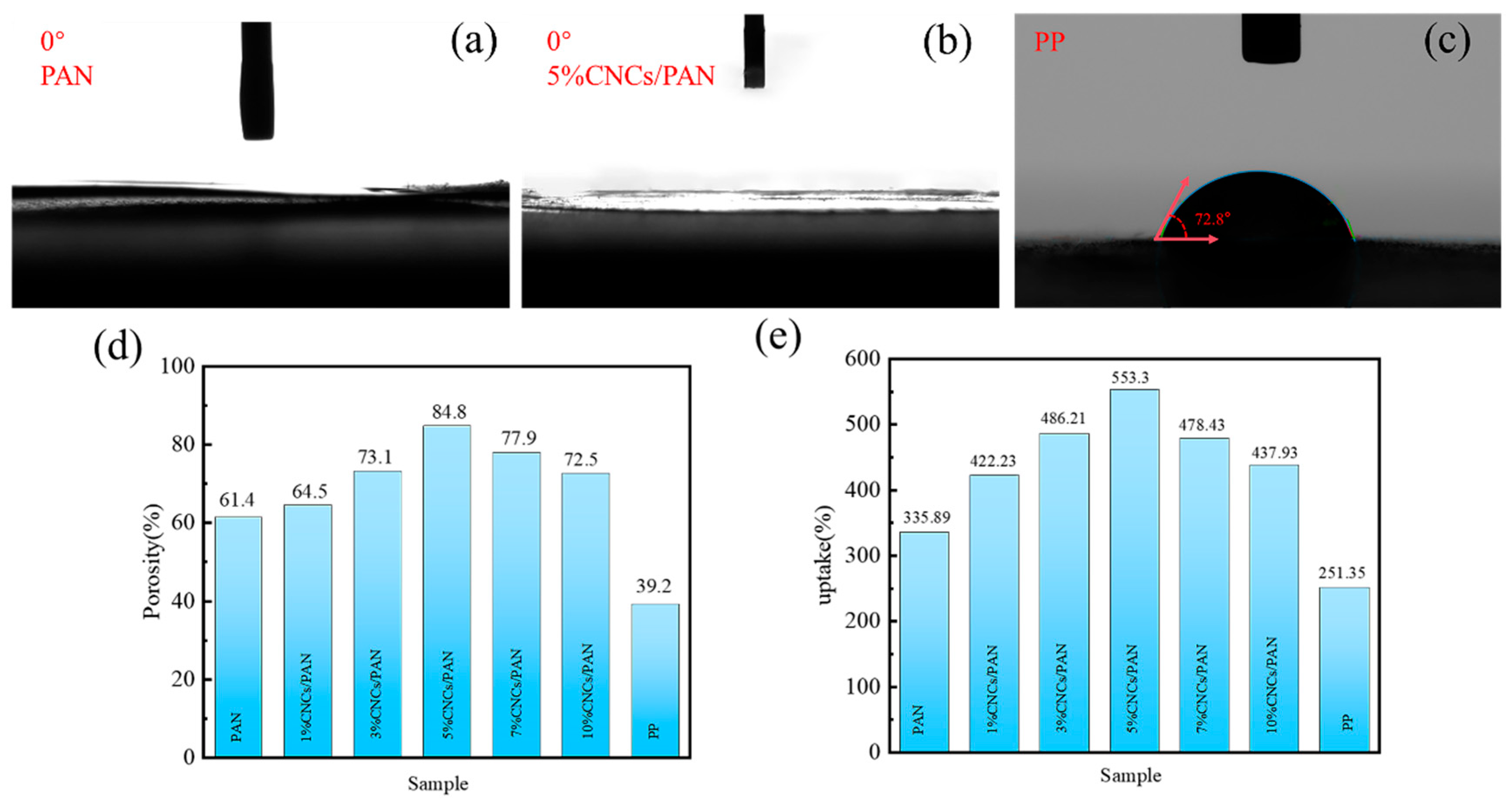
3.4. Uptake and Porosity of Separators

The ability of separators to absorb electrolyte is enhanced when the electrolyte wettability is optimal, which in turn facilitates the conveyance of Li+. The wettability of the electrolyte with respect to the separator can be evaluated by measuring the contact angle of the electrolyte with the separator. Figure 4a,b demonstrate that all the contact angles of the PAN separator, the 5%CNCs/PAN separator, and the other CNCs/PAN composite separators (Figure S2) are 0°, which demonstrates the enhanced wettability characteristics of the separators. These reduced contact angles are likely due to the increased porosity of the separators and the presence of polar hydroxyl (-OH) groups in the CNCs, which improve the separator’s compatibility and interaction with the electrolyte. Figure 4c indicates that the electrolyte contact angle of the commercial PP separator is 72.8°. The incorporation of CNCs results in a notable increase in the porosity and liquid absorption rate of the CNCs/PAN composite separators. The optimal 5% CNCs/PAN composite separator exhibits a porosity of 553.3% (Figure 4d), a significant improvement over the 251.35% observed in the commercial PP separator. The liquid absorption rate of the 5%CNCs/PAN composite separator (Figure 4e) reaches a maximum of 84.8% in comparison to the other CNCs/PAN separators and the PP separator. The PP separator shows the lowest absorption rate of only 39.2%. Compared with the PAN separator and PP, the 5%CNCs/PAN separator has higher porosity and adsorbs more electrolyte. As shown in the SEM images (Figure 2a,d), the surface of the 5%CNCs/PAN separator exhibits greater roughness compared to the PAN separator, contributing to an enhancement in porosity. The presence of a considerable number of -OH groups on the CNCs’ surfaces, coupled with their distinctive nano-morphology, results in a significant exposure of these groups to the external environment. These enhance the absorption of electrolytes, thereby improving the wettability of the CNCs/PAN composite separators and accelerating the rate of liquid absorption. Nevertheless, the elevated concentration of CNCs (>7%) results in a more pronounced phenomenon of agglomeration between the CNCs. The inability of the CNCs to be effectively dispersed in the PAN fibers led to a reduction in the porosity and liquid absorption rate of the separators.

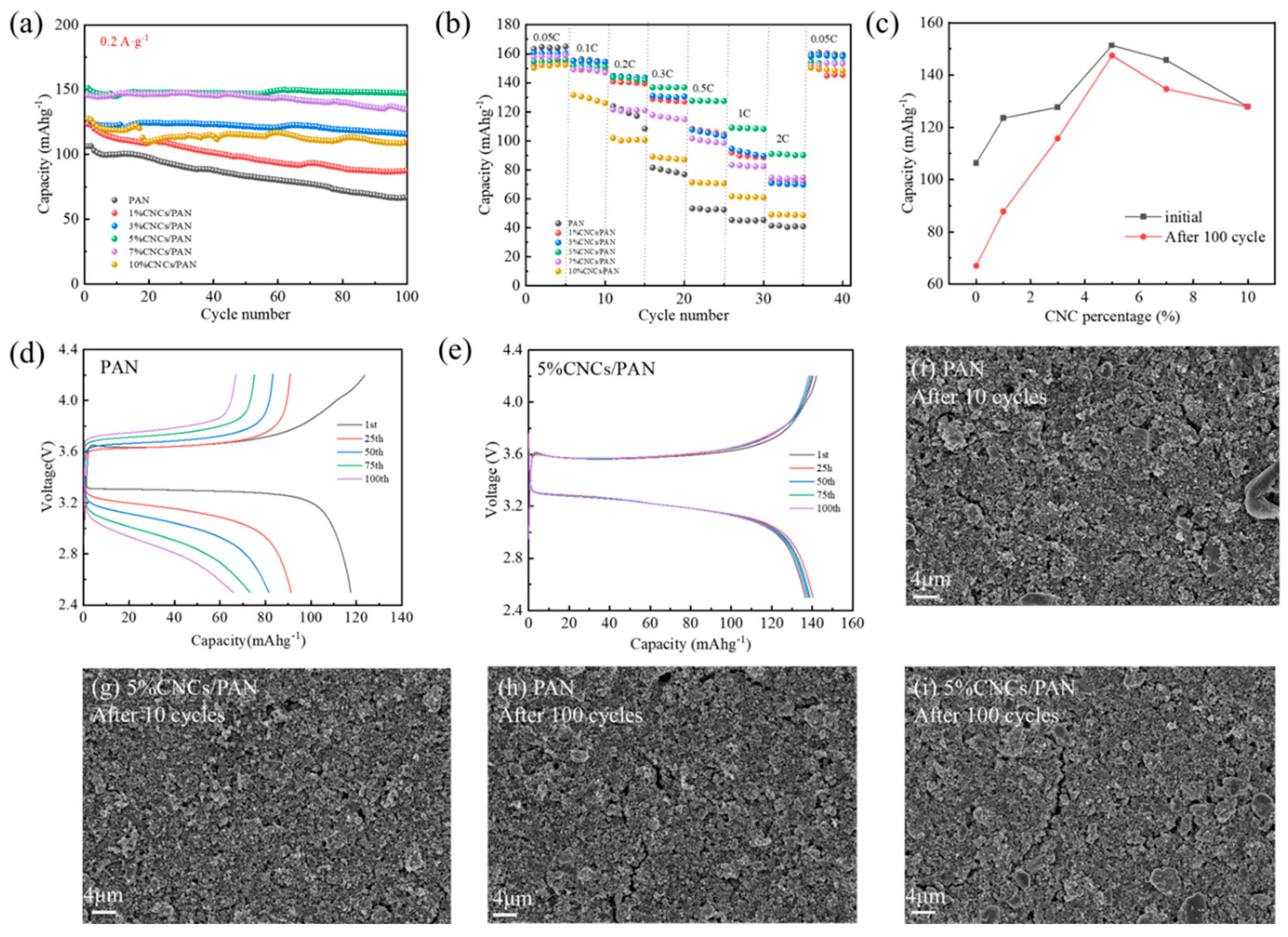
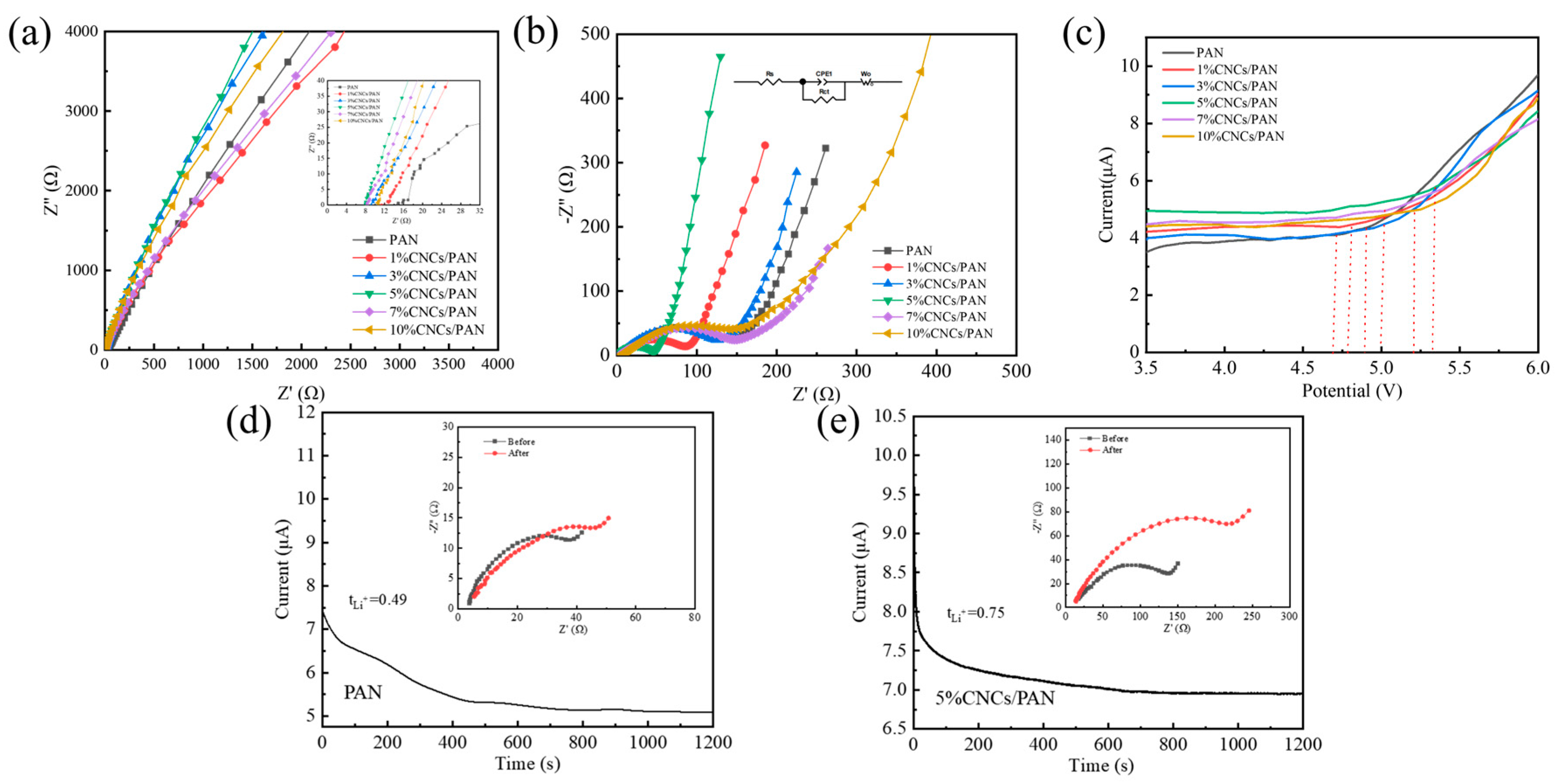
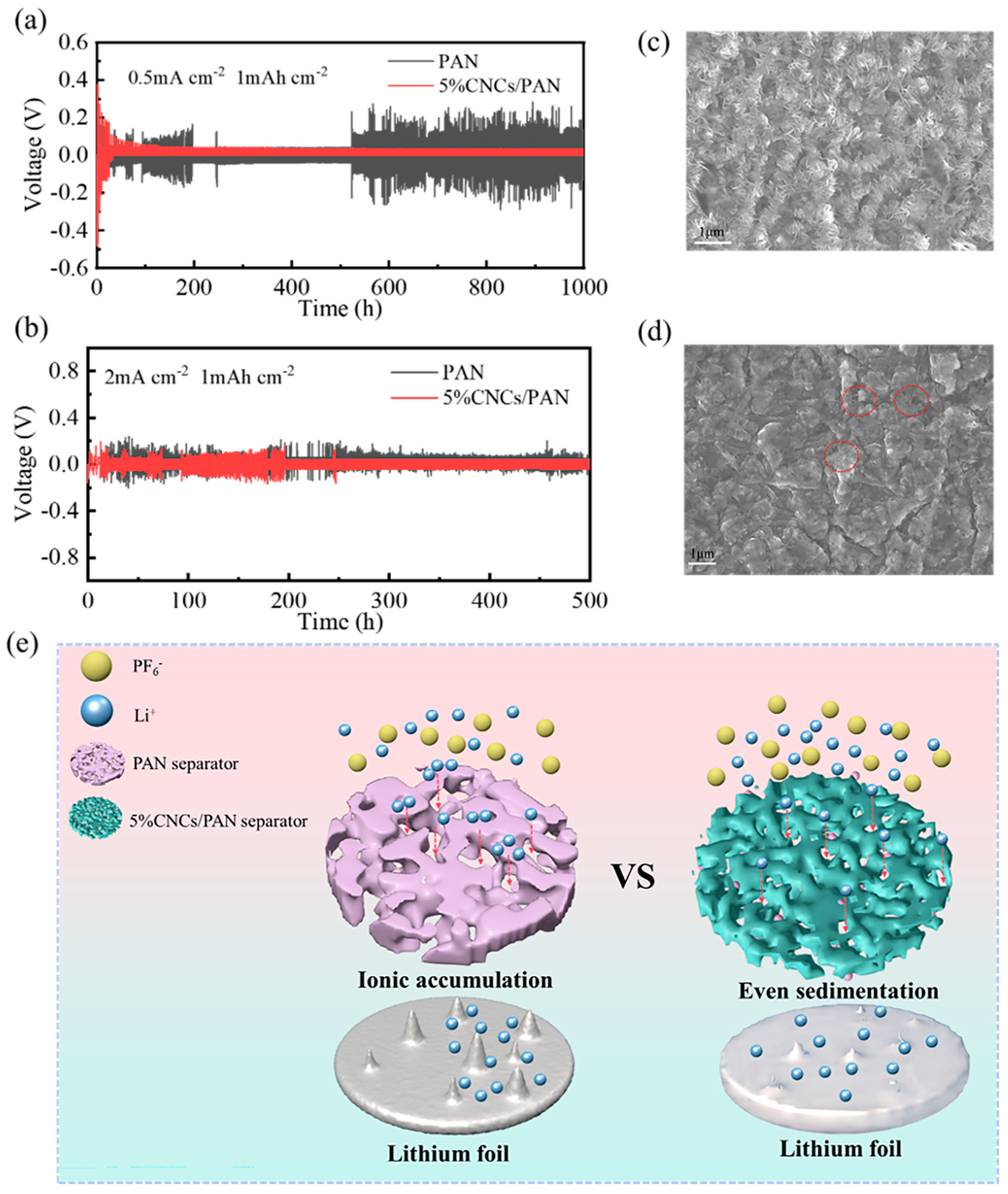
3.5. Electrochemical Properties of Separators

To further verify the suitability of CNCs/PAN composite separators for lithium-ion batteries, a LiFePO4/Li coin cells were subjected to charge–discharge cycling tests, with 100 cycles at a 0.2 A·g−1. Figure 5a illustrates that the specific capacities of all the cells decline with the increase in the number of cycles. After 100 charge–discharge cycles, the 5%CNCs/PAN composite separator exhibits the highest performance, retaining 97.4% of its initial specific capacity and reaching a specific capacity of 147.46 mAhg−1. The final specific capacity retention of the PAN is 62.9%, with a final specific capacity of 66.99 mAhg−1. The final specific capacity retentions of the 1%CNCs/PAN, 3%CNCs/PAN, 7%CNCs/PAN, and 10%CNCs/PAN are 71.1%, 90.8%, 92.6%, and 86.9%, respectively. Their final specific capacities are 87.81, 116.02, 134.98, and 127.83 mAhg−1, respectively. PAN is the least effective separator due to its larger pore size, which results in a bad electrolyte absorption capacity and reduces lithium-ion mobility. The enhanced specific capacity and specific capacity retention rate observed in the CNCs/PAN composite separators can be attributed to the presence of phosphoric acid-hydrolyzed cellulose nanocrystals, which contain a considerable number of -OH bonds. Their electrolyte compatibility is superior, facilitating greater electrolyte absorption. Conversely, the incorporation of CNCs leads to a uniform and reduced pore size within the diaphragm, thereby reducing localized shuttling and facilitating the uniform deposition of lithium ions onto the lithium sheet.
In order to characterize the separators’ charging and discharging performances at high power, rate performance tests for the cells were carried out. Figure 5b demonstrates the test plot of the rate performances of the cells with various separators. The capacity retention rates of the CNCs/PAN separators are markedly superior to that of the PAN separator when the discharge multiplication rate ranges from 0.05 C to 2 C. The 5%CNCs/PAN composite separator exhibits a specific capacity of 90.05 mAhg−1, even when subjected to a high discharge current density of 2 C. In comparison, the battery with the pure PAN separator demonstrates a significantly lower charging capacity of 40.92 mAhg−1. Upon returning the charging and discharging rate to 0.05 C, the cell charging specific capacities of the separators exhibited notable recoveries, with values approaching their initial values. This observation suggests that the capacity recovery behavior is indeed reversible. Figure 5c,d present the charging/discharging specific capacity curves of the PAN and 5%CNCs/PAN composite separators with varying numbers of cycle turns. The specific capacity of the PAN separator shows a steady decrease as the number of cycles progresses, dropping from an initial value of 119.6 mAhg−1 to 68.5 mAhg−1 by the 100th cycle. In contrast, the specific capacity of the 5%CNCs/PAN composite separator demonstrates minimal variation with the increase in the number of cycles, suggesting that the 5%CNCs/PAN composite separator exhibits enhanced stability in its performance. Figure 5c quantitatively delineates the evolution of gravimetric capacity during cycling, revealing a non-monotonic dependence on CNC loading. Both initial capacity and 100-cycle retention peak at 5% CNCs content, followed by progressive deterioration at higher loadings. This establishes a critical CNC concentration threshold (5 wt%), beyond which CNC aggregation-induced charge transfer impedance and compromised electrode–separator interfacial stability synergistically degrade cyclability. Figure 5d,e illustrate the surface morphology of the pole piece following 10 and 100 cycles of the PAN and 5%CNCs/PAN separators, respectively. As illustrated in Figure 5f,g, the Li||PAN separator||LiFePO4 cell exhibits fine cracks on the surface of the pole piece after 10 cycles. In contrast, cracks on the surface of the pole piece of the Li|| 5%CNCs/PAN separator||LiFePO4 cell are not readily apparent. As illustrated in Figure 5h,i, the presence of cracks in both pole pieces is evident after 100 cycles. However, the Li||PAN separator||LiFePO4 cell displays a greater prevalence of surface cracks and a more pronounced width of lines in comparison to the Li||5%CNCs/PAN separator||LiFePO4 cell. This CNCs/PAN separator has potential for application in the field of fast charge and discharge systems due to its excellent rate performance.
The ionic conductivities of the separators were calculated using EIS for the SS||separator||SS cells, as evidenced in Figure 6a, through the application of Equation (3). The ionic conductivities of the 1%CNCs/PAN, 3%CNCs/PAN, 5%CNCs/PAN, 7%CNCs/PAN, and 10%CNCs/PAN composite separators were found to be 1.31, 1.43, 2.82, 1.78, and 1.54 mS cm−1, respectively, while the ionic conductivity of the PAN separator was determined to be only 0.8 mS cm−1. The enhanced ionic conductivities of the CNCs/PAN separators, coupled with their enhanced wettability resulting from the incorporation of CNCs, may be attributed to the reduction in the strength of hydrogen bonding between the polymer network’s molecules, as well as the expansion of the amorphous regions associated with Li+, which collectively enhance ionic conductivity. The charge transfer resistance (Rct) of the “Li||separator||LiFePO4” configuration is determined through the analysis of the EIS. the diameter of the semicircle, indicating the charge transport resistance. An increase in Rct results in a reduction in the efficiency of Li+ transport. As observed in Figure 6b, the Rct of the Li||PAN separator||LiFePO4 cell is 216 Ω, while the Rcts of the Li||1%CNCs/PAN separator||LiFePO4 cell, Li||3%CNCs/PAN separator||LiFePO4 cell, Li||5%CNCs/PAN separator ||LiFePO4 cell, Li||7%CNCs/PAN separator ||LiFePO4 cell, and Li||10%CNCs/PAN separator||LiFePO4 cell are 150 Ω, 147 Ω, 93 Ω, 175 Ω, and 200 Ω, respectively. The Rcts of the Li||CNCs/PAN separator||LiFePO4 cells are consistently lower than that of the Li||pure PAN separator||LiFePO4 cell. This reduction can be ascribed to the incorporation of the CNCs, which enhance the electrolyte wettability. This improvement promotes the creation of additional pathways, enabling faster Li+ transport between the separator and the electrolyte. Furthermore, the Rcts of the 7%CNCs/PAN and 10%CNCs/PAN separators are higher than those of the 1%CNCs/PAN, 3%CNCs/PAN, and 5%CNCs/PAN separators due to the interfacial effects resulting from the structural defects in the polymer matrix caused by the agglomeration of excess CNCs. It is crucial for the CNCs/PAN separators to maintain their electrochemical stability when interacting with electrolytes and electrodes to avoid degradation and preserve mechanical integrity throughout the charge–discharge cycles. The Rct magnitudes of the cells employing different separators further corroborate the non-monotonic dependence of ionic conductivity on CNC loading, with the 5%CNCs/PAN composite separator achieving the minimal Rct value, indicative of optimal ionic transport characteristics at this critical composition. This behavior arises from CNC aggregation beyond the percolation threshold, which disrupts ionic/charge transfer kinetics through increased tortuosity pathways, thereby elevating charge transfer resistance. Concurrently, excessive CNC loading induces surface roughening of the separator and aggravated interfacial incompatibility with the electrodes. The electrochemical window range is indicative of the electrochemical stability of the separator. The LSV curves of six the distinct types of separators were subjected to evaluation, as illustrated in Figure 6c. When the electrode potential changes, the electric double layer at the electrode–electrolyte interface generates an instantaneous current through charge redistribution (similar to capacitor charging and discharging). This current is not related to the electron transfer of the electrochemical reaction, but is superimposed on the total current, especially at fast scan rates. Therefore, the current is not equal to 0 before the beginning of the degradation process [52]. Upon testing the LSV, the open-circuit voltage of the Li||separator||SS cell was observed to be approximately 3.5 V. The LSV curves in the lower voltage range are relatively smooth, indicating the absence of polarization phenomena or electrochemical reactions. The CNCs/PAN composite separators exhibit a minimal oxidation current, and the decomposition voltages of the CNCs/PAN separators are slightly elevated in comparison to that of the PAN separator. This phenomenon can be attributed to the favorable electrolyte affinities and high porosities of the CNCs/PAN separators, which enable the electrolyte to be retained within the separator voids in a secure and stable manner. The introduction of 5% concentration CNCs into PAN (with an electrochemical window of 4.72 V) has an electrochemical window up to 5.3 V, thereby conferring upon 5%CNCs/PAN a notable degree of electrochemical stability. The lithium-ion transference number (tLi+) has been demonstrated to exert a significant influence on the growth of Li+ dendrites during the processes of charging and discharging. The lithium-ion transference numbers were evaluated and the Li||separator||Li cell was constructed for impedance measurements prior to polarization. Subsequently, polarization was conducted at a fixed voltage of 10 mV for 1200 s, after which impedance tests were conducted once more. The ion mobility was calculated using Equation (4) (Figure S3), whereby the Li||separator||Li cell was assembled for impedance measurements prior to polarization. Figure 6d,e indicate the ion mobility numbers of 0.49 and 0.75 for the PAN and 5%CNCs/PAN composite separators, respectively. In the electrolyte, LiPF6 dissociates into Li+ and PF6, and both are transferred under the action of the electric field. The transfer of PF6 leads to a concentration polarization and induces an additional resistive force, whereas Li+ acts positively on ionic conduction. The function of the CNCs is not to absorb a greater quantity of electrolyte within the pores and on the surface, but also to facilitate the immobilization of PF6 ions through the CNCs. This process increases the migration number of lithium ions.
To evaluate the long-term interfacial stability of Li metal anodes in the context of these separators, Li||PAN separator||Li and Li||5%CNCs/PAN separator||Li symmetric cells were assembled. The voltage hysteresis of the Li||PAN separator||Li cell is consistently greater than that of the Li||5%CNCs/PAN separator||Li cell, irrespective of the current density. As illustrated in Figure 7a, the voltage of the Li||PAN separator||Li battery exhibits pronounced instability during the initial 200 h. This phenomenon may be due to the inherent instability of the interfacial layer on the surface of the lithium anode. Over the past 500 h, the voltage has exhibited increased instability, which may result from the diaphragm’s inability to provide a uniform channel for lithium ions. Additionally, the PAN separator’s aperture is relatively large, allowing for the aggregation of lithium ions within the PAN separator’s aperture of the lithium ions channel and the subsequent rapid passage of a considerable number of lithium ions through the diaphragm. This phenomenon gives rise to the formation of lithium dendritic crystals, which ultimately culminates in a short circuit of the battery. In contrast, the Li||5%CNCs/PAN separator||Li configuration exhibits not only a smaller overpotential but also a lower voltage over 160 h of operation within the cell steadily. This indicates a relatively consistent lithium plating/stripping process and the establishment of a stable interfacial layer on the surface of the lithium anode. This can be attributed to the relatively uniform pore shape and size of the modified diaphragm, which has been treated with CNCs. This results in a more regular path for Li+ ions when shuttling, and a reduced likelihood of ion aggregation at this pore size. As shown in Figure 7b, it can be observed that under conditions of high current density, both the Li||PAN separator||Li and the Li|| 5%CNCs/PAN separator||Li cells exhibit unstable voltage and a shorter cycle time, accompanied by an increase in overpotential. After 200 h, the Li||5%CNCs/PAN separator||Li cell gradually stabilizes, with a reduction in the fluctuations observed in its overpotential. In contrast, the Li||PAN separator||Li cell remains in an unstable state. This is due to the inability of the separator to strip lithium ions in a timely manner at high current densities, which facilitates the formation of lithium dendrites and their passage through the separator, leading to a short circuit. As illustrated in Figure 7c, the surface of the lithium wafer displays a considerable number of lithium dendrites after the cycling of Li||PAN separator||Li symmetric batteries for 1000 h at a current density of 0.5 mA cm−2. The generated dendrites are notably larger, increasing the likelihood of penetration through the diaphragm and resulting in a short circuit. However, as illustrated in Figure 7d, the Li||5%CNCs/PAN separator||Li symmetric cell exhibits much fewer lithium dendrites on the surface of the lithium wafers after 1000 h of cycling, with the dendrites being relatively small. It can be concluded from these results that the 5%CNCs/PAN composite separator has an inhibitory effect on the growth of dendrites.
The enhancement mechanism for electrochemical performance in 5%CNCs/PAN composite separator is shown in Figure 7e. In comparison with PAN separator, 5%CNCs/PAN composite separator possesses a greater quantity of hydroxyl groups, attributable to the incorporation of CNCs. The electrolyte is highly compatible with the 5%CNCs/PAN composite separator, ensuring a uniform distribution within the battery’s separator during the charging and discharging processes. The electrolyte enables the timely transmission of Li+ ions, facilitating the uniform shuttling of ions between the 5%CNCs/PAN composite separator and lithium, which avoids the formation of localized high concentrations. Concurrently, this process can allow sufficient time for the ions on the surface of the lithium wafer to be stripped, thus preventing the formation of lithium dendrites.

4. Conclusions

The successful preparation of a CNCs/PAN composite separator by electrostatic spinning has been achieved, and its application in a LiFePO4||separator||Li battery has been demonstrated. The 5%CNCs/PAN separator has been demonstrated to markedly enhance the rate performance of the battery cell, with a specific capacity of 151.4 mAh g−1. After 100 cycles, the battery capacity remains at 147.46 mAh g−1, with a capacity retention rate of 97.4%. In addition, the Li||separator||Li half-cell can be operated stably for more than 1000 h at a high current density of 0.5 mA cm−2. At room temperature, the 5% CNCs/PAN diaphragm exhibits a more expansive electrochemical window (5.3 V) and a higher concentration of Li+ (0.75) than the PAN separator. Furthermore, the utilization of diaphragms serves to diminish the interfacial impedance and enhance the interfacial stability of the battery. The 5%CNCs/PAN separator described in this paper is a highly promising candidate in fast-charging and high-energy-density discharging.

Supplementary Materials

The following supporting information can be downloaded at: https://www.mdpi.com/article/10.3390/coatings15030351/s1.

Author Contributions

A.Z.: Conceptualization; Methodology; Validation; Formal Analysis; Investigation; Data Curation; Writing—Original Draft; Writing—Review and Editing; Visualization. K.G.: Investigation; Methodology. X.L. (Xuenuan Li): Methodology; Data Curation; Formal Analysis. X.S.: Data Curation; Formal Analysis. X.L. (Xianming Liu): Validation; Investigation; Resources; Writing—Review and Editing. W.D.: Data Curation; Visualization. B.G.: Data Curation; Visualization. D.G.: Data Curation; Resources. G.L.: Data Curation; Resources. N.W.: Data Curation; Resources. A.Q.: Conceptualization; Resources; Data Curation; Writing—Original Draft; Writing—Review and Editing; Validation; Supervision; Project Administration; Funding Acquisition. All authors have read and agreed to the published version of the manuscript.

Funding

This work was supported by the Guangxi Key Technologies R&D Program (No. GuikeAB24010213), the Guangxi Natural Science Foundation (No. 2024GXNSFDA010015), the Guilin Key Technologies R&D Program (No.20230107-3), the National Natural Science Foundation of China (51564009), and the Innovation Project of Guangxi Graduate Education (YCBZ2024177).

Institutional Review Board Statement

Not applicable.

Informed Consent Statement

Not applicable.

Data Availability Statement

No data were used for the research described in the article.

Conflicts of Interest

The authors declare no conflict of interest.

References

  1. Likitaporn, C.; Prathumrat, P.; Senthilkumar, N.; Tanalue, N.; Wongsalam, T.; Okhawilai, M. Engineering the separators for high electrolyte uptakes in Li-ion batteries. J. Energy Storage 2024, 101, 113861. [Google Scholar] [CrossRef]
  2. Xie, J.; Chen, Q.; Zhang, H.; Song, R.; Liu, T. Recent developments of nanocomposite ionogels as monolithic electrolyte separators for lithium-based batteries. Battery Energy 2023, 3, 20230040. [Google Scholar] [CrossRef]
  3. Zhang, S.S. A review on the separators of liquid electrolyte Li-ion batteries. J. Power Sources 2007, 164, 351–364. [Google Scholar] [CrossRef]
  4. Heidari, A.A.; Mahdavi, H. Recent development of polyolefin-based microporous separators for Li-ion batteries: A Review. Chem. Rec. 2020, 20, 570–595. [Google Scholar] [CrossRef]
  5. Deng, H.; Qiao, Y.; Wu, S.; Qiu, F.; Zhang, N.; He, P.; Zhou, H. Nonaqueous, metal-free, and hybrid electrolyte Li-ion O2 battery with a single-ion-conducting separator. ACS Appl. Mater. Interfaces 2019, 11, 4908–4914. [Google Scholar] [CrossRef]
  6. Yuan, M.; Liu, K. Rational design on separators and liquid electrolytes for safer lithium-ion batteries. J. Energy Chem. 2020, 43, 58–70. [Google Scholar] [CrossRef]
  7. Hundekar, P.; Jain, R.; Lakhnot, A.S.; Koratkar, N. Recent advances in the mitigation of dendrites in lithium-metal batteries. J. Appl. Phys. 2020, 128, 010903. [Google Scholar] [CrossRef]
  8. Li, J.; Fleetwood, J.; Hawley, W.B.; Kays, W. From materials to cell: State-of-the-art and prospective technologies for Lithium-ion battery electrode processing. Chem. Rev. 2022, 122, 903–956. [Google Scholar] [CrossRef]
  9. Francis, C.F.J.; Kyratzis, I.L.; Best, A.S. Lithium-ion battery separators for ionic-liquid electrolytes:A Review. Adv. Mater. 2020, 32, e1904205. [Google Scholar] [CrossRef]
  10. Jana, K.K.; Lue, S.J.; Huang, A.; Soesanto, J.F.; Tung, K.L. Separator separators for High Energy-Density Batteries. ChemBioEng Rev. 2018, 5, 346–371. [Google Scholar] [CrossRef]
  11. Huang, X. Separator technologies for lithium-ion batteries. J. Solid State Electrochem. 2010, 15, 649–662. [Google Scholar] [CrossRef]
  12. Hao, H.; Hutter, T.; Boyce, B.L.; Watt, J.; Liu, P.; Mitlin, D. Review of multifunctional separators: Stabilizing the cathode and the anode for alkali (Li, Na, and K) metal-sulfur and selenium batteries. Chem. Rev. 2022, 122, 8053–8125. [Google Scholar] [CrossRef]
  13. Liu, Y.; Zhang, Z.; Du, X.; Wang, Y.; Guo, X.; Yu, M.; Liu, B.; Hu, W.; Shen, L.; Lu, Y.; et al. Poly(ether ether ketone) conferred polyolefin separators with high dimensional thermal stability for Lithium-ion batteries. ACS Appl. Mater. Interfaces 2023, 15, 37354–37360. [Google Scholar] [CrossRef]
  14. Yang, Y.; Wang, W.; Meng, G.; Zhang, J. Function-directed design of battery separators based on microporous polyolefin separators. J. Mater. Chem. A 2022, 10, 14137–14170. [Google Scholar] [CrossRef]
  15. Su, M.; Huang, G.; Wang, S.; Wang, Y.; Wang, H. High safety separators for rechargeable lithium batteries. Sci. China Chem. 2021, 64, 1131–1156. [Google Scholar] [CrossRef]
  16. Liu, M.; Deng, N.; Ju, J.; Fan, L.; Wang, L.; Li, Z.; Zhao, H.; Yang, G.; Kang, W.; Yan, J.; et al. A Review: Electrospun nanofiber materials for lithium-sulfur batteries. Adv. Funct. Mater. 2019, 29, 1905467. [Google Scholar] [CrossRef]
  17. Wang, J.; Wang, Z.; Ni, J.; Li, L. Electrospun materials for batteries moving beyond lithium-ion technologies. Electrochem. Energy Rev. 2021, 5, 211–241. [Google Scholar] [CrossRef]
  18. McMillin, C.R.; Fishback, T.; Harper, T.; Mussivand, T.; Kiraly, R.; Smith, W.; Navarro, R.; Nose, Y. Development of compliance chamber diaphragms with reduced permeability. J. BioMed Mater. Res. 1989, 23 (Suppl. S13), 117–128. [Google Scholar] [CrossRef]
  19. Li, L.; Peng, S.; Lee, J.K.Y.; Ji, D.; Srinivasan, M.; Ramakrishna, S. Electrospun hollow nanofibers for advanced secondary batteries. Nano Energy 2017, 39, 111–139. [Google Scholar] [CrossRef]
  20. Gao, X.; Sheng, L.; Yang, L.; Xie, X.; Li, D.; Gong, Y.; Cao, M.; Bai, Y.; Dong, H.; Liu, G.; et al. High-stability core-shell structured PAN/PVDF nanofiber separator with excellent lithium-ion transport property for lithium-based battery. J. Colloid Interface Sci. 2023, 636, 317–327. [Google Scholar] [CrossRef]
  21. Liang, T.; Liang, W.H.; Cao, J.H.; Wu, D.Y. Enhanced performance of high energy density lithium metal battery with PVDF-HFP/LAGP composite separator. ACS Appl. Energy Mater. 2021, 4, 2578–2585. [Google Scholar] [CrossRef]
  22. Nien, Y.H.; Chang, C.N.; Chuang, P.L.; Hsu, C.H.; Liao, J.L.; Lee, C.K. Fabrication and characterization of Nylon 66/PAN nanofibrous separator used as separator of lithium-ion battery. Polymers 2021, 13, 1984. [Google Scholar] [CrossRef] [PubMed]
  23. Jia, S.; Liang, Y.; Yang, N. High performance of polyacrylonitrile/[Mg-Al]-layered double hydroxide composite nanofiber separators for safe lithium-ion batteries. Solid State Ion. 2021, 370, 115735. [Google Scholar] [CrossRef]
  24. Yanilmaz, M.; Lu, Y.; Li, Y.; Zhang, X. SiO2/polyacrylonitrile separators via centrifugal spinning as a separator for Li-ion batteries. J. Power Sources 2015, 273, 1114–1119. [Google Scholar] [CrossRef]
  25. Liu, J.J.; Huang, Y.H.; Zhang, X.J.; Ding, Y.X.; Liu, H.; Gui, X.F. MOF-silsesquioxane synergistic modified hybrid porous separator for high-performance and high-safety lithium battery. Mater. Lett. 2024, 361, 136162. [Google Scholar] [CrossRef]
  26. Ju, Y.; Liu, H.; Chen, Y.; Sheng, J.; Zhai, Y.; Dong, B.; Cheng, R.; Zhou, Y.; Li, L. An ultrathin Zn-BDC MOF nanosheets functionalized polyacrylonitrile composite separator with anion immobilization and Li+ redistribution for dendrite-free Li metal battery. Compos. Commun. 2023, 37, 101449. [Google Scholar] [CrossRef]
  27. Liang, Y.; Lin, Z.; Qiu, Y.; Zhang, X. Fabrication and characterization of LATP/PAN composite fiber-based lithium-ion battery separators. Electrochim. Acta 2011, 56, 6474–6480. [Google Scholar] [CrossRef]
  28. Padmaraj, O.; Venkateswarlu, M.; Satyanarayana, N. Effect of PMMA blend and ZnAl2O4 fillers on ionic conductivity and electrochemical performance of electrospun nanocomposite polymer blend fibrous electrolyte separators for lithium batteries. RSC Adv. 2016, 6, 6486–6495. [Google Scholar] [CrossRef]
  29. Kopeć, M.; Lamson, M.; Yuan, R.; Tang, C.; Kruk, M.; Zhong, M.; Matyjaszewski, K.; Kowalewski, T. Polyacrylonitrile-derived nanostructured carbon materials. Prog. Polym. Sci. 2019, 92, 89–134. [Google Scholar] [CrossRef]
  30. Ding, W.; Xu, L. Batch fabrication of electrospun PAN/PU composite separators for safe lithium-ion batteries. Batteries 2023, 10, 6. [Google Scholar] [CrossRef]
  31. Mei, S.; Liu, T.; Chen, L.; Wang, Y. Preparation and performance of a PU/PAN lithium-ion battery separator based on a centrifugal spinning method. Appl. Sci. 2023, 13, 6682. [Google Scholar] [CrossRef]
  32. Zhang, W.; Tu, Z.; Qian, J.; Choudhury, S.; Archer, L.A.; Lu, Y. Design principles of functional polymer separators for high-energy, metal-based batteries. Small 2018, 14, e1703001. [Google Scholar] [CrossRef]
  33. Pan, R.; Wang, Z.; Sun, R.; Lindh, J.; Edström, K.; Strømme, M.; Nyholm, L. Thickness difference induced pore structure variations in cellulosic separators for lithium-ion batteries. Cellulose 2017, 24, 2903–2911. [Google Scholar] [CrossRef]
  34. Vu, A.; Qian, Y.; Stein, A. Porous electrode materials for lithium-ion batteries—How to prepare them and what makes them special. Adv. Energy Mater. 2012, 2, 1056–1085. [Google Scholar] [CrossRef]
  35. Luo, W.; Cheng, S.; Wu, M.; Zhang, X.; Yang, D.; Rui, X. A review of advanced separators for rechargeable batteries. J. Power Sources 2021, 509, 230372. [Google Scholar] [CrossRef]
  36. Bicy, K.; Gueye, A.B.; Rouxel, D.; Kalarikkal, N.; Thomas, S. Lithium-ion battery separators based on electrospun PVDF: A review. Surf. Interfaces 2022, 31, 101977. [Google Scholar] [CrossRef]
  37. Yang, C.; Jia, Z.; Guan, Z.; Wang, L. Polyvinylidene fluoride separator by novel electrospinning system for separator of Li-ion batteries. J. Power Sources 2009, 189, 716–720. [Google Scholar] [CrossRef]
  38. Xu, J.; Cai, X.; Cai, S.; Shao, Y.; Hu, C.; Lu, S.; Ding, S. High-energy lithium-ion batteries: Recent progress and a promising future in applications. Energy Environ. Mater. 2023, 6, e12450. [Google Scholar] [CrossRef]
  39. Yang, L.Y.; Cao, J.H.; Cai, B.R.; Liang, T.; Wu, D.Y. Electrospun MOF/PAN composite separator with superior electrochemical performances for high energy density lithium batteries. Electrochim. Acta 2021, 382, 138346. [Google Scholar] [CrossRef]
  40. Tang, L.; Wu, Y.; Lei, Z.; He, Y.; Chen, J. Electrospun PAN separators strengthened in situ–grown TiO2 particles for high-performance lithium-ion batteries. Ionics 2023, 29, 4669–4679. [Google Scholar] [CrossRef]
  41. Porporato, S.; Darjazi, H.; Gastaldi, M.; Piovano, A.; Perez, A.; Yécora, B.; Fina, A.; Elia, G.A.; Meligrana, G.; Gerbaldi, C. On the Use of Recycled PVB to Develop Sustainable Separators for Greener Li-Ion Batteries. Adv. Sustain. Syst. 2024, 9, 2400569. [Google Scholar] [CrossRef]
  42. Nagarajan, K.J.; Ramanujam, N.R.; Sanjay, M.R.; Siengchin, S.; Surya Rajan, B.; Sathick Basha, K.; Madhu, P.; Raghav, G.R. A comprehensive review on cellulose nanocrystals and cellulose nanofibers: Pretreatment, preparation, and characterization. Polym. Compos. 2021, 42, 1588–1630. [Google Scholar] [CrossRef]
  43. Kang, X.; Kuga, S.; Wang, C.; Zhao, Y.; Wu, M.; Huang, Y. Green preparation of cellulose nanocrystal and its application. ACS Sustain. Chem. Eng. 2018, 6, 2954–2960. [Google Scholar] [CrossRef]
  44. Xie, H.; Du, H.; Yang, X.; Si, C. Recent strategies in preparation of cellulose nanocrystals and cellulose nanofibrils derived from raw cellulose materials. Int. J. Polym. Sci. 2018, 2018, 7923068. [Google Scholar] [CrossRef]
  45. Lizundia, E.; Kundu, D. Advances in natural biopolymer-based electrolytes and separators for battery applications. Adv. Funct. Mater. 2020, 31, 2005646. [Google Scholar] [CrossRef]
  46. Li, X.; Wan, C.; Tao, T.; Chai, H.; Huang, Q.; Chai, Y.; Wu, Y. An overview of the development status and applications of cellulose-based functional materials. Cellulose 2023, 31, 61–99. [Google Scholar] [CrossRef]
  47. Chen, P.; Lin, X.; Yang, B.; Gao, Y.; Xiao, Y.; Li, L.; Zhang, H.; Li, L.; Zheng, Z.; Wang, J.; et al. Cellulose separators for rechargeable batteries with high safety: Advantages, strategies, and perspectives. Adv. Funct. Mater. 2024, 34, 2409368. [Google Scholar] [CrossRef]
  48. Sun, X.; Guo, J.; Zhi, X.; Xu, J.; Bian, Y.; Hou, K.; Li, X.; Wang, L.; Liang, G. Improved ionic conductivity and cycling stability via composite separator constructed by coating organic-modified sepiolite/PVDF layer on PP via electrospinning technology. Colloids Surf. A Physicochem. Eng. Asp. 2024, 691, 133925. [Google Scholar] [CrossRef]
  49. Liu, T.; Hu, X.; Zhang, Y.; He, T.; Zhou, J.; Qiao, J. Ion transport regulated lithium metal batteries achieved by electrospun ZIF/PAN composite separator with suitable electrolyte wettability. Batteries 2023, 9, 166. [Google Scholar] [CrossRef]
  50. Dong, G.X.; Li, H.J.; Wang, Y.; Jiang, W.J.; Ma, Z.S. Electrospun PAN/cellulose composite separator for high performance lithium-ion battery. Ionics 2021, 27, 2955–2965. [Google Scholar] [CrossRef]
  51. Chrissafis, K.; Bikiaris, D. Can nanoparticles really enhance thermal stability of polymers? Part I: An overview on thermal decomposition of addition polymers. Thermochim. Acta 2011, 523, 1–24. [Google Scholar] [CrossRef]
  52. Gambino, F.; Gastaldi, M.; Jouhara, A.; Malburet, S.; Galliano, S.; Cavallini, N.; Colucci, G.; Zanetti, M.; Fina, A.; Lia, G.A.; et al. Formulating PEO-polycarbonate blends as solid polymer electrolytes by solvent-free extrusion. J. Power Sources Adv. 2024, 30, 100160. [Google Scholar] [CrossRef]
Figure 1. Schematic illustration of construction processes of CNCs/PAN separator preparation by electrostatic spinning.
Coatings 15 00351 g001
Figure 2. (a) SEM image of PAN separator, (b) SEM image of 1%CNCs/PAN separator, (c) SEM image of 3%CNCs/PAN separator, (d) SEM image of 5%CNCs/PAN separator, (e) SEM image of 7%CNCs/PAN separator, and (f) SEM image of 10%CNCs/PAN separator. (g) FT-IR and (h) XRD patterns of PAN, 1%CNCs/PAN, 3%CNCs/PAN, 5%CNCs/PAN, 7%CNCs/PAN, and 10%CNCs/PAN separators.
Coatings 15 00351 g002
Figure 3. (a) Thermogravimetric, (b) thermal shrinkage and (c) mechanical strength comparisons of the PAN, 1%CNCs/PAN, 3%CNCs/PAN, 5%CNCs/PAN, 7%CNCs/PAN, and 10%CNCs/PAN separators.
Coatings 15 00351 g003
Figure 4. (ac) Electrolyte contact angle of PAN, 5%CNCs/PAN, and PP separators. (d) Porosity and (e) uptake of PAN, 1%CNCs/PAN, 3%CNCs/PAN, 5%CNCs/PAN, 7%CNCs/PAN, 10%CNCs/PAN and PP separators.
Coatings 15 00351 g004
Figure 5. (a) The charge–discharge cycling of the Li||separator||LiFePO4 cells with different separators at 0.2 C. (b) The rate performance of the Li||separator||LiFePO4 cells with different separators. (c) A plot of the addition of CNCs versus the specific capacity of the battery. (d) The charge–discharge profiles of the cells with a PAN separator. (e) The charge–discharge profiles of the cells with a 5%CNCs/PAN separator. (f) An SEM image of the surface of the LiFePO4 electrode of the Li||PAN separator||LiFePO4 cell after 10 turns of cycling. (g) An SEM image of the surface of the LiFePO4 electrode of the Li||5%CNCs/PAN separator||LiFePO4 cell after 10 turns of cycling. (h) An SEM image of the surface of the LiFePO4 electrode of the Li||PAN separator||LiFePO4 cell after 100 turns of cycling. (i) An SEM image of the surface of the LiFePO4 electrode of the Li||5%CNCs/PAN separator||LiFePO4 cell after 100 turns of cycling.
Coatings 15 00351 g005
Figure 6. (a) Nyquist plots of the SS||PAN separator||SS cell and SS||CNCs/PAN separators||SS cell. (b) A comparison of the AC impedance of the Li||PAN separator||Li cell and Li||CNCs/PAN separators||Li cells. (c) The LSV curves of the Li||PAN separator||SS cell and Li|| CNCs/PAN separators||SS cells at a scan rate of 10 mVs−1. (d) The change in current over time during the polarization of the Li||PAN separator||Li cell under a constant potential step of 10 mV at room temperature. (e) The change in current over time during the polarization of the Li||5%CNCs/PAN separator||Li cell under a constant potential step of 10 mV at room temperature.
Coatings 15 00351 g006
Figure 7. (a) Galvanostatic plating/stripping curves for Li||separator||Li symmetric cells using PAN and 5%CNCs/PAN separators at current density and capacity of 0.5 mA cm−2 and 1 mAh cm−2, respectively. (b) Galvanostatic plating/stripping curves for Li||separator||Li symmetric cells using PAN and 5%CNCs/PAN separators at current density and capacity of 2 mA cm−2 and 1 mAh cm−2, respectively. (c) SEM image of lithium wafer surface after 1000 h of cycling Li||PAN separator||Li symmetric cells at 0.5 mA cm−2. (d) SEM image of lithium wafer surface after 1000 h of cycling Li||5%CNCs/PAN separator||Li symmetric cells at 0.5 mA cm−2. (e) Schematic illustration of enhancement mechanism for electrochemical performance in composite separator.
Coatings 15 00351 g007
Disclaimer/Publisher’s Note: The statements, opinions and data contained in all publications are solely those of the individual author(s) and contributor(s) and not of MDPI and/or the editor(s). MDPI and/or the editor(s) disclaim responsibility for any injury to people or property resulting from any ideas, methods, instructions or products referred to in the content.

