

Low-Friction Coatings Grown on Cemented Carbides by Modulating the Sputtering Process Parameters of TiN Targets


Abstract
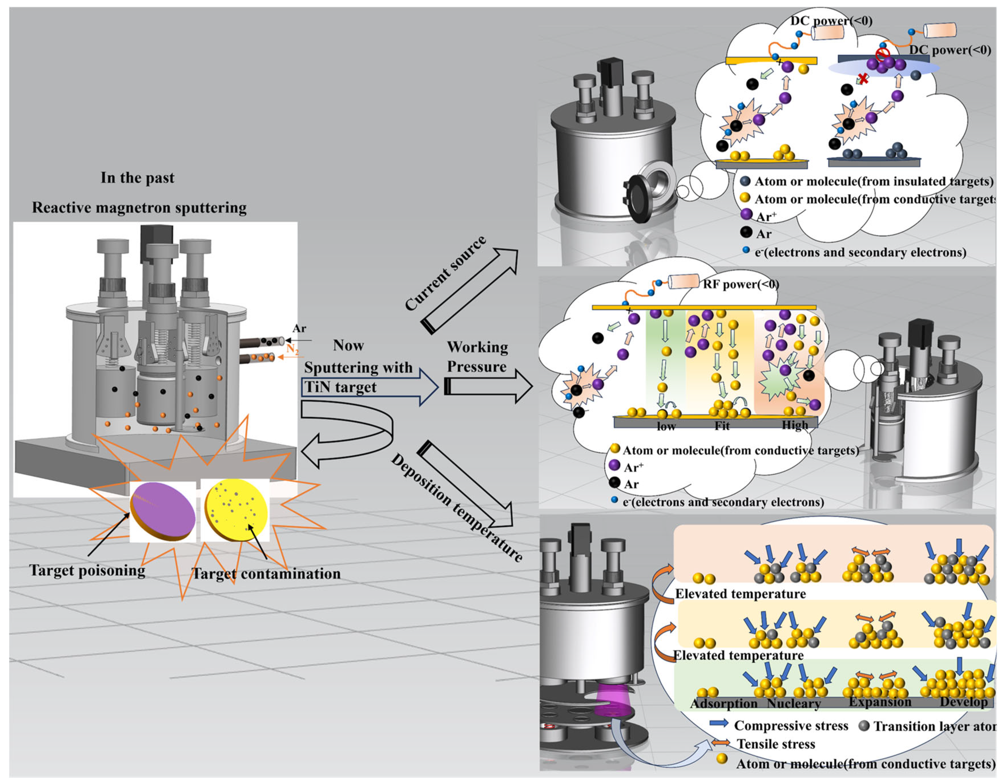
1. Introduction
2. Experiments
2.1. Equipment and Materials
2.2. Experimental Procedures
2.3. Coating Characterisation
3. Results and Discussion
3.1. Effect of Different Current Sources on Coating Properties
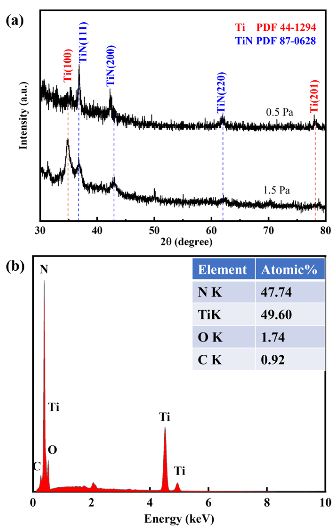
3.2. Effect of Ar Pressure on the Properties of TiN Coatings
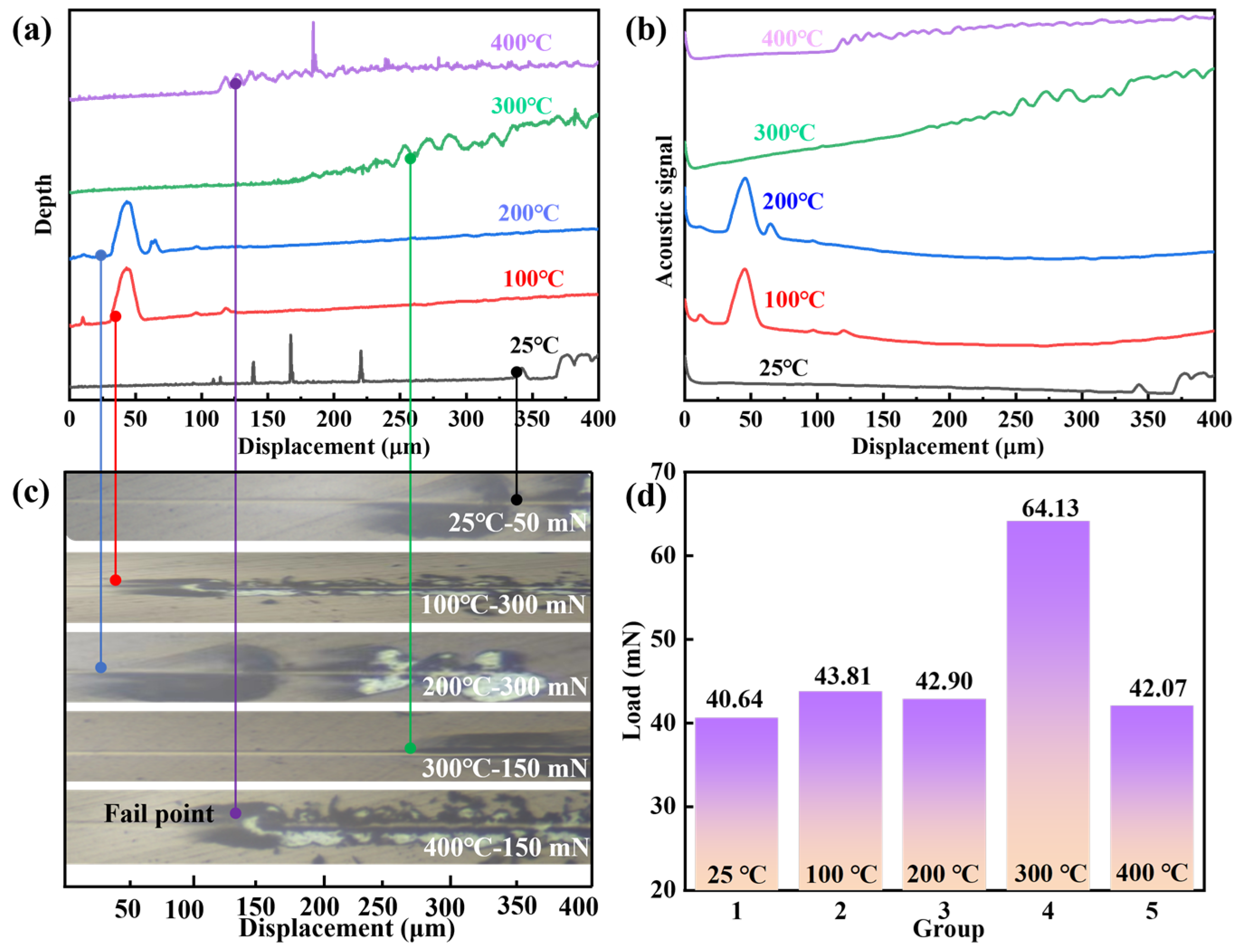
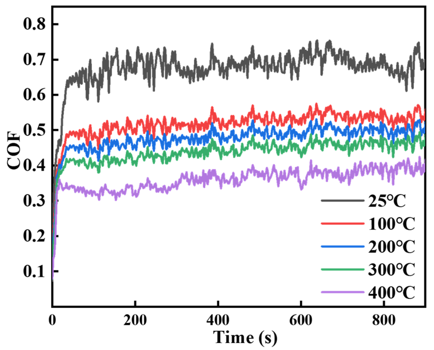
3.3. Effect of Deposition Temperature on TiN Coatings
4. Conclusions
Supplementary Materials
Author Contributions
Funding
Institutional Review Board Statement
Informed Consent Statement
Data Availability Statement
Conflicts of Interest
References
- Subhedar, D.G.; Chauhan, K.V.; Patel, D.A. An experimental investigation of TiN coating on cutting force and surface finish in milling of aluminium. Mater. Today Proc. 2022, 59, 161–165. [Google Scholar] [CrossRef]
- Chang, C.-L.; Lo, K.-C.; Yang, F.-C.; Shen, G.-L.; Tang, J.-F. HiPIMS co-sputtering for the increase of the mechanical properties of arc deposited TiN coatings. J. Mater. Res. Technol. 2023, 26, 2050–2059. [Google Scholar] [CrossRef]
- Klocke, F.; Krieg, T. Coated Tools for Metal Cutting–Features and Applications. CIRP Ann. 1999, 48, 515–525. [Google Scholar] [CrossRef]
- Xian, G.; Xiong, J.; Fan, H.; Jiang, F.; Guo, Z.; Zhao, H.; Xian, L.; Jing, Z.; Liao, J.; Liu, Y. Investigations on microstructure, mechanical and tribological properties of TiN coatings deposited on three different tool materials. Int. J. Refract. Met. Hard Mater. 2022, 102, 105700. [Google Scholar] [CrossRef]
- Dubar, M.; Dubois, A.; Dubar, L. Wear analysis of tools in cold forging: PVD versus CVD TiN coatings. Wear 2005, 259, 1109–1116. [Google Scholar] [CrossRef]
- von Fieandt, L.; Larsson, T.; Lindahl, E.; Bäcke, O.; Boman, M. Chemical vapor deposition of TiN on transition metal substrates. Surf. Coat. Technol. 2018, 334, 373–383. [Google Scholar] [CrossRef]
- Das, S.; Guha, S.; Ghadai, R.; Sharma, A. Influence of nitrogen gas over microstructural, vibrational and mechanical properties of CVD Titanium nitride (TiN) thin film coating. Ceram. Int. 2021, 47, 16809–16819. [Google Scholar] [CrossRef]
- Miao, J.; Song, J.; Xue, Y.; Tong, Y.; Tang, W.; Lu, F. Effect of a two-step pretreatment method on adhesion of CVD diamond coatings on cemented carbide substrates. Surf. Coat. Technol. 2004, 187, 33–36. [Google Scholar] [CrossRef]
- Kumar, A.; Mulik, R.S. Improving tribological behavior of titanium nitride (TiN) hard coatings via zirconium (Zr) or vanadium (V) doping. Tribol. Int. 2023, 189, 108997. [Google Scholar] [CrossRef]
- Teyssandier, F.; Allendorf, M.D. Thermodynamics and Kinetics of Gas-Phase Reactions in the Ti-Cl-H System. J. Electrochem. Soc. 2019, 145, 2167–2178. [Google Scholar] [CrossRef]
- Zeng, Y.; Qiu, Y.; Mao, X.; Tan, S.; Tan, Z.; Zhang, X.; Chen, J.; Jiang, J. Superhard TiAlCN coatings prepared by radio frequency magnetron sputtering. Thin Solid Film 2015, 584, 283–288. [Google Scholar] [CrossRef]
- Zhang, X.; Qiu, Y.; Tan, Z.; Lin, J.; Xu, A.; Zeng, Y.; Moore, J.J.; Jiang, J. Effect of Al content on structure and properties of TiAlCN coatings prepared by magnetron sputtering. J. Alloys Compd. 2014, 617, 81–85. [Google Scholar] [CrossRef]
- Saoula, N.; Bait, L.; Sali, S.; Azibi, M.; Hammouche, A.; Madaoui, N. Reactive Magnetron Sputter Deposition of Titanium Oxynitride TiNxOy Coatings: Influence of Substrate Bias Voltage on the Structure, Composition, and Properties. Prot. Met. Phys. Chem. Surf. 2019, 55, 743–747. [Google Scholar] [CrossRef]
- Richter, N.A.; Yang, B.; Barnard, J.P.; Niu, T.; Sheng, X.; Shaw, D.; Watanabe, M.; Rane, G.; Krause, U.; Dürrenfeld, P.; et al. Significant texture and wear resistance improvement of TiN coatings using pulsed DC magnetron sputtering. Appl. Surf. Sci. 2023, 635, 157709. [Google Scholar] [CrossRef]
- Kataria, S.; Srivastava, S.K.; Kumar, P.; Srinivas, G.; Siju; Khan, J.; Rao, D.V.S.; Barshilia, H.C. Nanocrystalline TiN coatings with improved toughness deposited by pulsing the nitrogen flow rate. Surf. Coat. Technol. 2012, 206, 4279–4286. [Google Scholar] [CrossRef]
- Vaz, F.; Ferreira, J.; Ribeiro, E.; Rebouta, L.; Lanceros-Méndez, S.; Mendes, J.A.; Alves, E.; Goudeau, P.; Rivière, J.P.; Ribeiro, F.; et al. Influence of nitrogen content on the structural, mechanical and electrical properties of TiN thin films. Surf. Coat. Technol. 2005, 191, 317–323. [Google Scholar] [CrossRef]
- Zhou, T.; Liu, D.; Zhang, Y.; Ouyang, T.; Suo, J. Microstructure and hydrogen impermeability of titanium nitride thin films deposited by direct current reactive magnetron sputtering. J. Alloys Compd. 2016, 688, 44–50. [Google Scholar] [CrossRef]
- Shuai, J.; Zuo, X.; Wang, Z.; Guo, P.; Xu, B.; Zhou, J.; Wang, A.; Ke, P. Comparative study on crack resistance of TiAlN monolithic and Ti/TiAlN multilayer coatings. Ceram. Int. 2020, 46, 6672–6681. [Google Scholar] [CrossRef]
- Tien, S.-K.; Lin, C.-H.; Tsai, Y.-Z.; Duh, J.-G. Oxidation behavior, microstructure evolution and thermal stability in nanostructured CrN/AlN multilayer hard coatings. J. Alloys Compd. 2010, 489, 237–241. [Google Scholar] [CrossRef]
- Huang, Y.; Chen, Z.; Wagner, A.; Mitterer, C.; Song, K.; Zhang, Z. High density of stacking faults strengthened TaN/TiN multilayer. Acta Mater. 2023, 255, 119027. [Google Scholar] [CrossRef]
- Fallmann, M.; Chen, Z.; Zhang, Z.L.; Mayrhofer, P.H.; Bartosik, M. Mechanical properties and epitaxial growth of TiN/AlN superlattices. Surf. Coat. Technol. 2019, 375, 1–7. [Google Scholar] [CrossRef]
- Li, H.; Liu, Y.; Jiang, B.; Kan, J.; Liu, Z. The structure and toughness of TiN coatings prepared by modulated pulsed power magnetron sputtering. Vacuum 2016, 125, 165–169. [Google Scholar] [CrossRef]
- Arudi, I.S.; Hamzah, E.; Yajid, M.A.M.; Bushroa, A.R.; Munshi, S.M.; Al-Ashhab, M.S.; Ibrahim, M.Z. Taguchi optimization of hardness and scratch adhesion strength of multilayer Ti/TiN coatings on Ti- 51 at%Ni alloy deposited via magnetron sputtering technique. J. Mater. Res. Technol. 2023, 27, 7664–7672. [Google Scholar] [CrossRef]
- Pei, Y.T.; Galvan, D.; De Hosson, J.T.M. Nanostructure and properties of TiC/a-C:H composite coatings. Acta Mater. 2005, 53, 4505–4521. [Google Scholar] [CrossRef]
- Bräuer, G.; Szyszka, B.; Vergöhl, M.; Bandorf, R. Magnetron sputtering–Milestones of 30 years. Vacuum 2010, 84, 1354–1359. [Google Scholar] [CrossRef]
- Yuan, Z.; Han, Y.; Zang, S.; Chen, J.; He, G.; Chai, Y.; Yang, Z.; Fu, Q. Damage evolution behavior of TiN/Ti multilayer coatings under high-speed impact conditions. Surf. Coat. Technol. 2021, 426, 127807. [Google Scholar] [CrossRef]
- Castanho, J.M.; Vieira, M.T. Effect of ductile layers in mechanical behaviour of TiAlN thin coatings. J. Mater. Process. Technol. 2003, 143–144, 352–357. [Google Scholar] [CrossRef]
- Fu, Z.; Koc, R. Nanoindentation mechanical properties of TiB2-TiC-TiNiFeCrCoAl high-entropy alloys cermet: A comparison study with WC-Co. Int. J. Refract. Met. Hard Mater. 2021, 98, 105564. [Google Scholar] [CrossRef]
- Braic, M.; Zoita, N.C.; Danila, M.; Grigorescu, C.E.A.; Logofatu, C. Hetero-epitaxial growth of TiC films on MgO(001) at 100 °C by DC reactive magnetron sputtering. Thin Solid Film 2015, 589, 590–596. [Google Scholar] [CrossRef]
- Qi, Q.; Zhang, W.Z.; Shi, L.Q.; Zhang, W.Y.; Zhang, W.; Zhang, B. Preparation of single-crystal TiC (111) by radio frequency magnetron sputtering at low temperature. Thin Solid Film 2012, 520, 6882–6887. [Google Scholar] [CrossRef]
- Veprek, S.; Karvankova, P.; Veprek-Heijman, M.G.J. Possible role of oxygen impurities in degradation of nc-TiN∕a-Si3N4 nanocomposites. J. Vac. Sci. Technol. B Microelectron. Nanometer Struct. Process. Meas. Phenom. 2005, 23, L17–L21. [Google Scholar] [CrossRef]
- Oliver, W.C.; Pharr, G.M. An improved technique for determining hardness and elastic modulus using load and displacement sensing indentation experiments. J. Mater. Res. 2011, 7, 1564–1583. [Google Scholar] [CrossRef]
- Yu, H.Z.; Thompson, C.V. Grain growth and complex stress evolution during Volmer–Weber growth of polycrystalline thin films. Acta Mater. 2014, 67, 189–198. [Google Scholar] [CrossRef]
- Kumar, M.; Mitra, R. Effect of substrate temperature and annealing on structure, stress and properties of reactively co-sputtered Ni-TiN nanocomposite thin films. Thin Solid Film 2017, 624, 70–82. [Google Scholar] [CrossRef]
- Pao, C.-W.; Srolovitz, D.J. Stress and Morphology Evolution during Island Growth. Phys. Rev. Lett. 2006, 96, 186103. [Google Scholar] [CrossRef]
- Patro, S.S.; Sahoo, A.K.; Roy, S. Analysis of residual stresses in cutting tools coated via physical vapour deposition: A review. Mater. Today Proc. 2023. [Google Scholar] [CrossRef]
- Romano-Brandt, L.; Salvati, E.; Le Bourhis, E.; Moxham, T.; Dolbnya, I.P.; Korsunsky, A.M. Nano-scale residual stress depth profiling in Cu/W nano-multilayers as a function of magnetron sputtering pressure. Surf. Coat. Technol. 2020, 381, 125142. [Google Scholar] [CrossRef]
- Vierneusel, B.; Schneider, T.; Tremmel, S.; Wartzack, S.; Gradt, T. Humidity resistant MoS2 coatings deposited by unbalanced magnetron sputtering. Surf. Coat. Technol. 2013, 235, 97–107. [Google Scholar] [CrossRef]
- Li, X.; Li, G.; Lü, W.; Liu, S.; Li, C.; Wang, Q. Controllable high adhesion and low friction coefficient in TiAlCN coatings by tuning the C/N ratio. Appl. Surf. Sci. 2022, 597, 153542. [Google Scholar] [CrossRef]
- Tillmann, W.; Grisales, D.; Stangier, D.; Thomann, C.-A.; Debus, J.; Nienhaus, A.; Apel, D. Residual stresses and tribomechanical behaviour of TiAlN and TiAlCN monolayer and multilayer coatings by DCMS and HiPIMS. Surf. Coat. Technol. 2021, 406, 126664. [Google Scholar] [CrossRef]
- Bai, Y.; Xi, Y.; Gao, K.; Yang, H.; Pang, X.; Volinsky, A.A. Residual stress control in CrAlN coatings deposited on Ti alloys. Ceram. Int. 2018, 44, 4653–4659. [Google Scholar] [CrossRef]
- Escobar, D.; Ospina, R.; Gómez, A.G.; Restrepo-Parra, E. Microstructure, residual stress and hardness study of nanocrystalline titanium–zirconium nitride thin films. Ceram. Int. 2015, 41, 947–952. [Google Scholar] [CrossRef]


| Substrate | Amount | Dimensions (mm) | Serve as |
|---|---|---|---|
| Si (111) | 2 | 10 × 10 × 0.5 | Microscopic morphology, physical phase testing, etc. |
| YG8 | 2 | Φ 20 × 2.5 | Mechanical performance test. |
| Number | Current Sources | Power (W) | Ar Gas Pressure (Pa) | Sputtering Time (min) | Substrate Temperature (°C) |
|---|---|---|---|---|---|
| S1 | DC | 120 | 1.5 | 120 | 25 |
| S2 | RF | 120 | 1.5 | 120 | 25 |
| S3 | RF | 120 | 0.5 | 120 | 25 |
| S4 | RF | 120 | 0.5 | 120 | 100 |
| S5 | RF | 120 | 0.5 | 120 | 200 |
| S6 | RF | 120 | 0.5 | 120 | 300 |
| S7 | RF | 120 | 0.5 | 120 | 400 |
Disclaimer/Publisher’s Note: The statements, opinions and data contained in all publications are solely those of the individual author(s) and contributor(s) and not of MDPI and/or the editor(s). MDPI and/or the editor(s) disclaim responsibility for any injury to people or property resulting from any ideas, methods, instructions or products referred to in the content. |
© 2025 by the authors. Licensee MDPI, Basel, Switzerland. This article is an open access article distributed under the terms and conditions of the Creative Commons Attribution (CC BY) license (https://creativecommons.org/licenses/by/4.0/).
Share and Cite
Qiao, H.; Liu, M.; Xiang, Y.; Xu, X.; Wang, Z.; Wu, W.; Wang, Y. Low-Friction Coatings Grown on Cemented Carbides by Modulating the Sputtering Process Parameters of TiN Targets. Coatings 2025, 15, 329. https://doi.org/10.3390/coatings15030329
Qiao H, Liu M, Xiang Y, Xu X, Wang Z, Wu W, Wang Y. Low-Friction Coatings Grown on Cemented Carbides by Modulating the Sputtering Process Parameters of TiN Targets. Coatings. 2025; 15(3):329. https://doi.org/10.3390/coatings15030329
Chicago/Turabian StyleQiao, Hu, Minghui Liu, Ying Xiang, Xiling Xu, Ze Wang, Wenxuan Wu, and Youqing Wang. 2025. "Low-Friction Coatings Grown on Cemented Carbides by Modulating the Sputtering Process Parameters of TiN Targets" Coatings 15, no. 3: 329. https://doi.org/10.3390/coatings15030329
APA StyleQiao, H., Liu, M., Xiang, Y., Xu, X., Wang, Z., Wu, W., & Wang, Y. (2025). Low-Friction Coatings Grown on Cemented Carbides by Modulating the Sputtering Process Parameters of TiN Targets. Coatings, 15(3), 329. https://doi.org/10.3390/coatings15030329