
Research Progress on Post-Treatment Technologies of Cold Spray Coatings

Abstract
1. Introduction
2. Thermal Processing
2.1. Heat Treatment
2.2. Laser Remelting

| References | Coatings | LR Parameters | Findings |
|---|---|---|---|
| [48] | Cu402F | Spot diameter: 4 mm Scan speed: 200 mm/s Laser power: 2500 W | LR retains the CS coating’s original merits and accelerates the formation rate of the passivation film during the abrasion process, thereby significantly enhancing its abrasion resistance. |
| [49] | Cu402F | Spot diameter: 1 mm Scan speed: 500 mm/s Laser power: 2900 W | LR significantly improves the coating’s corrosion resistance, which is attributed to the stable passivation film formed on the surface after a certain period, effectively protecting the internal structure. |
| [45,46] | Ti | Spot diameter: 2 mm Scan speed: 10–1000 mm/s Laser power: 220 W | Following LR, the remelting zone’s hardness is significantly enhanced due to grain refinement and the formation of acicular martensite. |
| [47] | Ti | Spot diameter: 0.3–1.08 mm Scan speed: 21.6–48.3 mm/s Laser power: 440–1000 W | LR effectively eliminates pores within the coating and forms an oxide layer on its surface, thereby significantly enhancing the coating’s corrosion resistance. |
| [50] | Ti | Spot diameter: 2 mm Scan speed: 50 mm/s Laser power: 200 W | LR formed a hard oxide layer on the coating’s surface, altering the wear mechanism of the Ti coating from adhesive wear to abrasive wear, thereby significantly enhancing its wear resistance. |
| [51] | Ti-6Al-4V | Spot diameter: 1 mm Scan speed: 20 mm/s Laser power: 50–200 W | The surface roughness and hardness of the coating exhibit a positive correlation with the increase in laser power, consequently enhancing its wear resistance. |
| [52] | Ti/Cr3C2 | Spot diameter: 2.4 mm Scan speed: 20–100 mm/s Laser power: 0.5–2000 W | LR facilitated the reaction between Ti and Cr3C2, forming two new phases, β-Ti(Cr) and TiCx, within the coating. This significantly enhanced the coating’s hardness and wear resistance. |
| [30] | WC/Ti | Spot diameter: 3.8 × 1.2 mm Scan speed: 8 mm/s Laser power: 200–800 W | LR effectively improves the coating’s sliding wear resistance, which is attributed to the formation of the hard TiC phase. |
| [53] | Al | Spray distance: 250 mm Spot diameter: 5 mm Laser power: 800 W Argon gas speed: 8 L/min | After undergoing LR, the coating’s initially porous structure becomes densified, the grain size is significantly reduced, and the hardness and wear resistance are markedly enhanced. |
| [44] | Al | Spray distance: 250 mm Spot diameter: 5 mm Laser power: 800 W Argon gas speed: 8 L/min | Following LR, the coating’s residual compressive stress increased by 26%, enhancing the bonding strength between the coating and the substrate. This improvement effectively prevents coating delamination. |
| [54] | Al/Si | Spot diameter: 40 μm Scan speed: 1000 mm/s Laser power: 200–300 W | LR densifies the coating, refines its structure, and significantly reduces surface roughness. |
| [55] | IN625 | Heat input: 14–28 J/mm Scan speed: 25–50 mm/s Laser power: 700 W | LR decreases the coating’s porosity and enhances its elastic modulus. However, the columnar dendrite structure developed in the remelting layer reduces the coating’s hardness. |
| [56] | 316L | Spot diameter: 1.4 mm Scan speed: 100 mm/s Laser power: 500 W | LR significantly reduces the coating’s porosity, exhibits minimal thermal impact on the substrate, and markedly enhances its corrosion resistance. |
3. Mechanical Processing
3.1. Friction Stirring
| References | Coatings | FSP Parameters | Findings |
|---|---|---|---|
| [67] | Al | Stir tool material: H13 steel Shoulder diameter: 16 mm Concave shoulder angle: 2.5° Rotation speed: 1500 rpm Traverse speed: 9–18 mm/min | After the coating underwent FSP treatment, its conductivity was markedly enhanced due to defect elimination. Additionally, the bonding strength between the coating and the substrate was significantly improved due to intermetallic compound formation. |
| [68] | Al | Stir tool material: H13 steel Shoulder diameter: 16 mm Rotation speed: 2100–3000 rpm Traverse speed: 1 mm/min | FSP markedly enhances the coating’s corrosion resistance. The formation of the Al12Mg17 intermetallic compound leads to a substantial improvement in coating hardness. |
| [69] | AA7075 | Stir tool material: H13 steel Shoulder diameter: 12 mm Concave shoulder angle: 3° Pin diameter: 1.7 mm Pin height: 1.5 mm Rotation speed: 1120 rpm Traverse speed: 22.4 mm/min | After FSP, the coating’s hardness increased more than threefold owing to the refined grain structure, enhanced material mixing, and strengthened bonding between the coating and the substrate. |
| [70,71] | AA2024/Al2O3 | Stir tool material: H13 steel Shoulder diameter: 10 mm Concave shoulder angle: 2.5° Pin diameter: 3.4 mm Pin height: 2.9 mm Rotation speed: 1500 rpm/900 rpm Traverse speed: 100 mm/min//50 mm/min | FSP refines and disperses the Al2O3 particles within the coating, significantly enhancing its tensile properties. Additionally, by improving the coating’s surface condition, FSP also enhances its corrosion resistance. |
| [65,72] | SiC/5056Al | Shoulder diameter: 10 mm Concave shoulder angle: 2.5° Pin diameter: 3.4 mm Pin height: 2.9 mm Rotation speed: 600–1400 rpm Traverse speed: 100 mm/min | FSP significantly enhances the coating’s density, refines the Al matrix grains into fine equiaxed crystals, and fully fractures and evenly disperses the SiC particles. This process consequently improves the coating’s hardness and wear resistance. |
| [73] | 6061Al/CoCrFeNi | Stir tool material: H13 steel Shoulder diameter: 18 mm Concave shoulder angle: 2.5° Pin diameter: 7 mm Pin height: 3.8 mm Rotation speed: 1200 rpm Traverse speed: 45 mm/min | After FSP treatment, the pores within the coating are eliminated, and the reinforced particles attain full metallurgical bonding with the matrix. Consequently, the coating’s tensile strength and ductility are significantly enhanced. |
| [64] | Cu60-Zn40 | Shoulder diameter: 10 mm Concave shoulder angle: 2.5° Pin diameter: 3.4 mm Pin height: 1.5 mm Rotation speed: 1500 rpm Traverse speed: 100 mm/min | After FSP, the coating predominantly consists of high-angle grain and twin boundaries, substantially increasing tensile strength. |
| [74] | Cu-10Ti3SiC2 | Shoulder diameter: 9 mm Rotation speed: 500–700 rpm Traverse speed: 50 mm/min | FSP significantly refines the coating’s grain structure, enhances the bonding between the coating and the substrate, and improves its electrical conductivity, tensile strength, and ductility. |
| [75] | Al-Cu-Ni | Concave shoulder angle: 1.1–1.5° Rotation speed: 600–1200 rpm Traverse speed: 100–1200 mm/min | FSP substantially enhanced the homogeneity and phase composition of the coating, resulting in the formation of two new phases: AlNi and Al2Cu. Additionally, the integrity of the FSP-treated coating surpassed that of the LR-treated coating. |
| [76] | CuAlNi/Al2O3 | Stir tool material: WC Shoulder diameter: 10 mm Rotation speed: 360 rpm Traverse speed: 20 mm/min | FSP can substantially refine the coating’s grain structure and ensure a uniform distribution of Al2O3 particles, thereby significantly enhancing the coating’s elastic modulus, hardness, and sliding wear resistance. |
| [77] | Ti | Stir tool material: WC Shoulder diameter: 12 mm Concave shoulder angle: 2.5° Rotation speed: 900 rpm Traverse speed: 63 mm/min | FSP can achieve full coating densification, with grain refinement to less than 1 μm. The coating hardness reaches up to 700 HV, seven times higher than that of the sprayed coating. |
| [78] | Ni50-Ti50 | Stir tool material: W-Re Shoulder diameter: 15 mm Concave shoulder angle: 2.5° Rotation speed: 1500 rpm Traverse speed: 100 mm/min | Following the FSP process, an array of intermetallic compounds was generated, substantially enhancing the coating’s hardness and wear resistance. |
| [63] | Ni-Nb-Si | Shoulder diameter: 10 mm Concave shoulder angle: 2.5° Pin diameter: 3 mm/6 mm Pin height: 2.7 mm Rotation speed: 500 rpm Traverse speed: 30 mm/min//50 mm/min | FSP can significantly improve the composite coating’s corrosion resistance in molten glass, benefiting from the densification and alloying of the materials. |
| [61] | Diamalloy 1003 (Similar to 316L) | Stir tool material: WC Shoulder diameter: 15 mm Concave shoulder angle: 1.5° Pin diameter: 4 mm Pin height: 1.4 mm Rotation speed: 300 rpm Traverse speed: 50 mm/min | The coating underwent complete recrystallization during the FSP process, eliminating defects such as pores and cracks. This led to the formation of a dense and uniform fine-grained microstructure. |
| [79] | WC-CoCr/Al2O3 | Stir tool material: W-Re/pcBN Shoulder diameter: 18 mm/25.4 mm Concave shoulder angle: 2°/0° Pin diameter: 5 mm Pin height: 5.7 mm/5.75 mm Rotation speed: 250 rpm/800 rpm Traverse speed: 100 mm/min//76 mm/min | FSP facilitates the uniform dispersion of deposited WC-CoCr aggregates and refines Al2O3 particles, enhancing the homogeneity of coating hardness and corrosion resistance. |
3.2. Shot Peening
| References | Coatings | SP Parameters | Findings |
|---|---|---|---|
| [82] | Al//Al/Al2O3 | Ball material: S230 cast iron Diameter: 0.6 mm Stand-of-distance: 380 mm Pressure: 0.15 MPa Exposure time: 33 s Coverage: 200% | SP can effectively harden the coating’s surface; however, it has minimal impact on the residual stress state within the coating. |
| [83] | Al | Ball material: 1Cr18 ss Diameter: 0.25–0.33 mm Stand-of-distance: 20 mm Pressure: 1 MPa | After the SP, the coating’s porosity is reduced to merely 0.2%. The coating’s densification significantly enhances its corrosion resistance. |
| [86] | 6082Al | Ball material: S230 cast iron Diameter: 0.6 mm Coverage: 100% and 800% | SP does not enhance the coating’s fatigue strength further. Initial cracks under fatigue loading originate from the damage inflicted by SP on the coating. |
| [87] | Zn | Ball material: 1Cr18 ss Diameter: 0.2–0.3 mm Stand-of-distance: 80 mm Pressure: 0.05–0.2 MPa Exposure time: 600 s Coverage: 200% | SP significantly enhances the coating’s density, leading to a substantial increase in hardness and a twofold improvement in corrosion resistance compared to spray coatings. |
| [88] | Ti-6Al-4V | Ball material: S100 steel Diameter: 0.3 mm Pressure: 0.0689–0.4137 MPa | SP decreases the porosity of the coating surface. The surface hardness improves as the shot peening pressure increases, enhancing its resistance to abrasive wear. |
| [89] | NiCrAlY | Ball material: Glass bead grit Diameter: 0.3 mm Stand-of-distance: 150 mm Pressure: 0.3 MPa | By decreasing the coating’s surface roughness, SP facilitates the development of a homogeneous protective oxide film during post-treatment, thereby significantly enhancing the coating’s oxidation resistance. |
4. Thermo-Mechanical Processing
Hot Rolling
5. Chemical Processing
Chemical Conversion Coating
| References | Coatings | CCC Parameters | Findings |
|---|---|---|---|
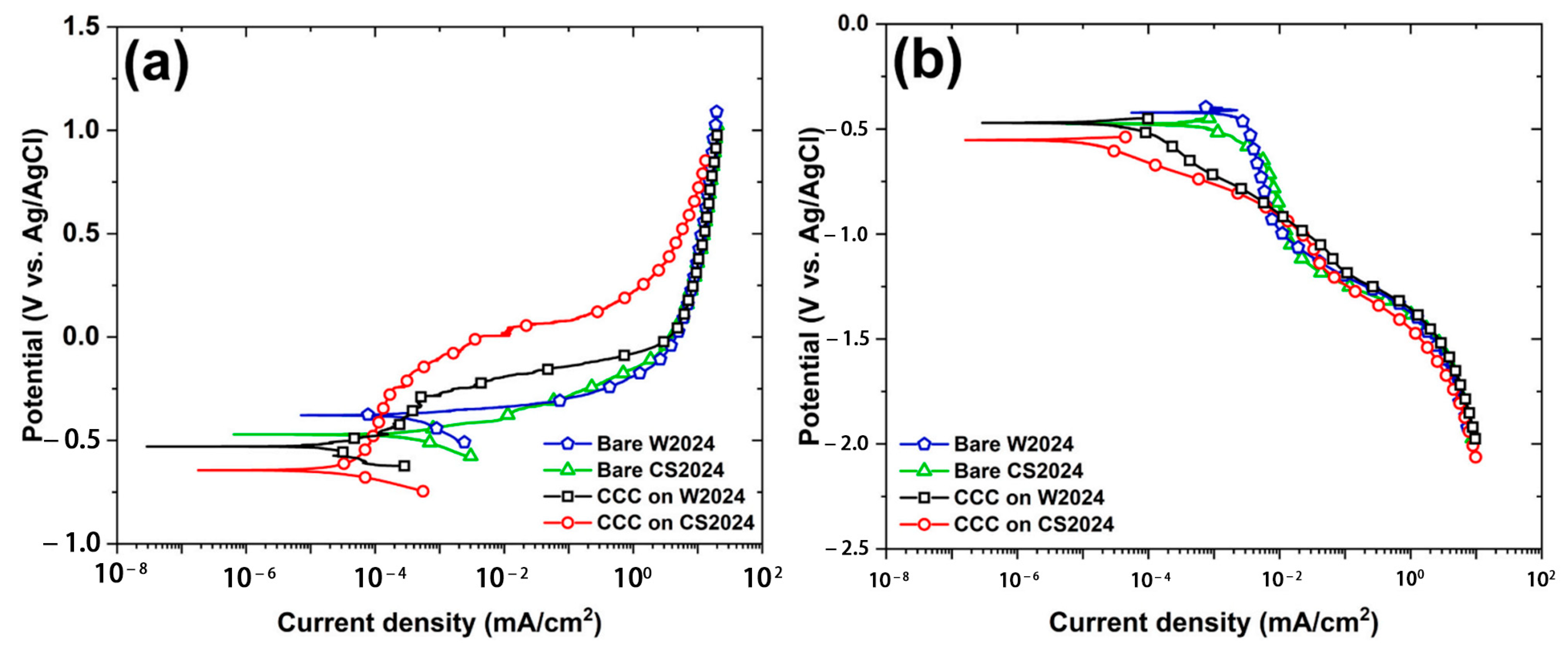
| [114] | 2024Al | Transforming agents: Alodine 1201 Span: 3 min | The corrosion expansion caused by the unique morphology of CCC on CS2024 is the primary cause of its sharp decrease in corrosion resistance with time. |
6. Electrochemical Processing
6.1. Anodic Oxidation
| References | Coatings | Anodic Oxidation Parameters | Findings | |
|---|---|---|---|---|
| Electrolyte Composition | Electrical Parameters | |||
| [118,120] | Ti | 5 wt% H2O 0.5 wt% NH4F 94.5 wt% (CH2OH)2 | Voltage: 30 V Span: 45 min | AO can significantly improve the hydrophilicity of CS coating and then promote cell proliferation and differentiation, mainly due to the TiO2 nanotube structure formed on the coating’s surface. |
| [119] | Al | 10 wt% H2SO4 90 wt% H2O | Anode current density: 2 A/dm2 Span: 40 min | The dense alumina film formed by anodizing effectively improves the coating’s corrosion and wear resistance. |
| [121] | Al | Sulfuric acid solution | Voltage: 13~22 V Current density: 1~2 A/dm2 Span: 30 min | When the coating’s porosity exceeds 1.5%, its corrosion resistance after anodizing is significantly reduced. This is attributed to the difficulty forming a dense oxide layer due to the electrolyte’s infiltration. |
| [122] | Al/Al2O3 | 0~10 vol.% H2SO4 | Voltage: 0~30 V Span: 0~90 min | The optimum anodizing process for the coating surface is 10% sulfuric acid concentration, 25 V voltage, and 60 min oxidation time, at which time the highest hardness and wear resistance can be obtained. |
| [123,124] | Sn | [H2C2O4] = 0.3 mol/L | Voltage: 6 V Span: 10 min | The nanoporous SnO films obtained by cold spraying Sn coating after AO and water-assisted heat treatment have good capacitance characteristics. They can be used as potential electrode materials for energy storage applications. |
| [125] | 7075Al/Al2O3//G/7075Al/Al2O3 | 70 wt% 0.3 mol/L H2C2O4 30 wt% C2H5OH | Voltage: 60 V Span: 30 min | The introduction of graphene improves the density and bonding strength of the coating while exerting high strength and lubrication anti-wear properties. The hardness and wear resistance of the AO layer are also significantly improved. |
6.2. Plasma Electrolytic Oxidation
| References | Coatings | PEO Parameters | Findings | |
|---|---|---|---|---|
| Electrolyte Composition | Electrical Parameter | |||
| [128] | Al | [Na2SiO3] = 1.65 g/L [KOH] = 1 g/L | Frequency: 100 Hz Anode current density: 48 A/dm2 Qp/Qn = 0.9 Span: 8–35 min | Compared with the single-phase PEO process of blocks, the growth kinetics of the biphase CS + PEO oxide layer is three times higher, mainly due to the higher porosity of the CS coating. |
| [135] | Al | [Na2SiO3] = 9 g/L [NaOH] = 5 g/L [NaF] = 0.5 g/L [SiO2] = 3 g/L | Voltage: 450 V Span: 20 min | PEO coating is mainly composed of α-Al2O3 and γ-Al2O3, accompanied by a small amount of Al, and its corrosion resistance is higher than that of Al coating. |
| [136] | Al | [NaAlO2] = 7.5 g/L [KOH] = 1 g/L [Na3PO4] = 2.5 g/L | Voltage: 500 V Frequency: 500 Hz Duty cycle: 40% Span: 5 min | After PEO, the wear resistance of Al coating is greatly improved due to the formation of a high-hardness and dense oxide layer. |
| [131] | Al// Al/α-Al2O3 | [Na2SiO3] = 1.65 g/L [KOH]= 1 g/L | Frequency: 100 Hz Anode current density: 66 A/dm2 Cathode current density: 39 A/dm2 Qp/Qn = 0.9 Span: 20–35 min | In the PEO process, α-Al2O3 particles are crushed and melted by the arc and uniformly dispersed in the oxide layer, improving the coating’s wear resistance. |
| [133] | Al// Al/α-Al2O3 | [NaAlO2] = 0.18 mol/L [KOH] = 0.035 mol/L | Voltage: 400 V Frequency: 500 Hz Duty cycle: 60% Span: 20 min | PEO significantly improves the corrosion resistance and wear resistance of Al coating, and the addition of α-Al2O3 can enhance the improvement effect. |
| [137] | Al/α-Al2O3 | [Na2SiO3] = 5 g/L [KOH] = 1 g/L | Anode current density: 30 A/dm2 Cathode current density: 33.33 A/dm2 Qp/Qn = 0.9 and ∞ Span: 22 min | The oxidation layer grows faster in soft spark mode than in unipolar mode; the higher α-Al2O3 content and dense oxide layer structure improves wear resistance. |
| [138] | Al// Al/CNT | [NaAlO2] = 8 g/L [KOH] = 1 g/L [EDTA-2Na] = 2 g/L [Na3C6H5O7·2H2O] = 2 g/L | Frequency: 2000 Hz Positive current: 0.6 A Negative current: 0.3 A Duty cycle: 20% Span: 10 min | The wear resistance of the composite coating is greatly improved after PEO, thanks to the hard oxide layer and the strengthening and self-lubrication of carbon elements. |
| [139] | 7075Al | [NaAlO2] = 8 g/L [KOH] = 1 g/L [EDTA-2Na] = 2 g/L [Na3C6H5O7·2H2O] = 2 g/L | Frequency: 2000 Hz Positive current: 0.5 A Negative current: 0.3 A Duty cycle: 20% Span: 10 min | The PEO oxide layer is dominated by γ-Al2O3, accompanied by a small amount of α-Al2O3, and the hardness is as high as 1353 HV0.01. The corrosion and wear resistance of the Al7075 coating are greatly improved. |
| [140] | Zr/Al | [Na2SiO3] = 1.65 g/L [KOH] = 1 g/L | Frequency: 100 Hz Anode current density: 65 A/dm2 Qp/Qn = 0.9 Span: 20 min | The feasibility of preparing a ZrO2/Al2O3 composite coating on a cold-sprayed Zr/Al coating surface by PEO is demonstrated. |
| [141] | Ti | [Na2SiO3] = 30 g/L | Voltage: 380 V Frequency: 400 Hz Duty cycle: 10% Span: 7 min | The rough and porous structure of Ti-PEO coating results in poor mechanical properties and wear resistance, but the more stable chemical properties of the oxide may improve corrosion resistance. |
7. Conclusions and Outlook
- (1)
- The enhancement effects of post-treatment technologies on the microstructure and properties of CS coatings are influenced not only by post-treatment parameters but also by the intrinsic characteristics of coating materials and CS processing conditions, with these factors exhibiting interconnected and complex interdependencies. However, systematic investigations into their synergistic mechanisms remain scarce, and consensus regarding optimal process parameters for most materials has yet to be established, which should be prioritized in future research endeavors to address current technological limitations.
- (2)
- The incorporation of ceramic reinforcement particles demonstrates significant potential for enhancing the wear resistance, mechanical properties, and multifunctional performance of CS coatings. However, due to the relatively low temperatures inherent to the deposition process, ceramic particles exhibit limited plastic deformation capacity, with interfacial interactions between metallic and ceramic constituents being predominantly governed by mechanical bonding mechanisms, thus resulting in composite coatings characterized by inadequate interfacial adhesion and susceptibility to brittle fracture. Consequently, such hybrid systems require post-treatment interventions to optimize interfacial bonding strength and fully exploit the reinforcement potential of ceramic particulates. Although current research in this domain remains limited, systematic investigations into bonding mechanisms and the development of advanced post-processing methodologies using integrated experimental and numerical simulation approaches represent critical imperatives for technological advancement.
- (3)
- Current post-treatment technologies predominantly remain at experimental research stages with inherent limitations, demonstrating restricted optimization efficacy primarily targeting one or two specific properties under particular operational conditions while failing to achieve substantial comprehensive performance enhancement of CS coatings using singular processing methods. Future developments should prioritize the strategic integration of multiple post-treatment approaches, such as hybrid techniques exemplified by HT + SP and LR + SP + PEO composite technologies, to leverage complementary advantages that collectively address the comprehensive performance requirements of CS coatings under diverse complex service conditions.
Author Contributions
Funding
Conflicts of Interest
References
- Papyrin, A.; Kosarev, V.; Klinkov, S.; Alkimov, A.; Fomin, V. Cold spray technology. Adv. Mater. Process. 2001, 159, 49–51. [Google Scholar]
- Yin, S.; Cavaliere, P.; Aldwell, B.; Jenkins, R.; Liao, H.; Li, W.; Lupoi, R. Cold spray additive manufacturing and repair: Fundamentals and applications. Addit. Manuf. 2018, 21, 628–650. [Google Scholar] [CrossRef]
- Cadney, S.; Brochu, M.; Richer, P.; Jodoin, B. Cold gas dynamic spraying as a method for freeforming and joining materials. Surf. Coat. Technol. 2008, 202, 2801–2806. [Google Scholar] [CrossRef]
- Assadi, H.; Kreye, H.; Gärtner, F.; Klassen, T. Cold spraying—A materials perspective. Acta Mater. 2016, 116, 382–407. [Google Scholar] [CrossRef]
- Rokni, M.; Nutt, S.; Widener, C.; Champagne, V.; Hrabe, R. Review of Relationship Between Particle Deformation, Coating Microstructure, and Properties in High-Pressure Cold Spray. J. Therm. Spray Technol. 2017, 26, 1308–1355. [Google Scholar] [CrossRef]
- Ajdelsztajn, L.; Schoenung, J.; Jodoin, B.; Kim, G. Cold spray deposition of nanocrystalline aluminum alloys. Metall. Mater. Trans. A 2005, 36, 657–666. [Google Scholar] [CrossRef]
- Li, C.; Li, W.; Wang, Y. Formation of metastable phases in cold-sprayed soft metallic deposit. Surf. Coat. Technol. 2005, 198, 469–473. [Google Scholar] [CrossRef]
- Suo, X.; Guo, X.; Li, W.; Planche, M.P.; Bolot, R.; Liao, H.; Coddet, C. Preparation and characterization of magnesium coating deposited by cold spraying. J. Mater. Process. Technol. 2012, 212, 100–105. [Google Scholar] [CrossRef]
- Spencer, K.; Fabijanic, D.; Zhang, M. The use of Al–Al2O3 cold spray coatings to improve the surface properties of magnesium alloys. Surf. Coat. Technol. 2009, 204, 336–344. [Google Scholar] [CrossRef]
- Gardon, M.; Latorre, A.; Torrell, M.; Dosta, S.; Guilemany, J.M. Cold Gas Spray Titanium coatings onto a biocompatible polymer. Mater. Lett. 2013, 106, 97–99. [Google Scholar] [CrossRef]
- Sun, W.; Tan, A.W.; Wu, K.; Yin, S.; Yang, X.; Marinescu, I.; Liu, E. Post-Process Treatments on Supersonic Cold Sprayed Coatings: A Review. Coatings 2020, 10, 123. [Google Scholar] [CrossRef]
- Li, W.; Cao, C.; Yin, S. Solid-state cold spraying of Ti and its alloys: A literature review. Prog. Mater. Sci. 2020, 110, 100633. [Google Scholar] [CrossRef]
- Wang, H.; Li, P.; Guo, W.; Ma, G.; Wang, H. Copper-Based Composite Coatings by Solid-State Cold Spray Deposition: A Review. Coatings 2023, 13, 479. [Google Scholar] [CrossRef]
- Siddique, S.; Bernussi, A.A.; Husain, S.W.; Yasir, M. Enhancing structural integrity, corrosion resistance and wear properties of Mg alloy by heat treated cold sprayed Al coating. Surf. Coat. Technol. 2020, 394, 1258–1282. [Google Scholar] [CrossRef]
- Sun, W.; Bhowmik, A.; Tan, A.W.-Y.; Li, R.; Xue, F.; Marinescu, I.; Liu, E. Improving microstructural and mechanical characteristics of cold-sprayed Inconel 718 deposits via local induction heat treatment. J. Alloys Compd. 2019, 797, 1268–1279. [Google Scholar] [CrossRef]
- Chavan, N.M.; Ramakrishna, M.; Phani, P.S.; Rao, D.S.; Sundararajan, G. The influence of process parameters and heat treatment on the properties of cold sprayed silver coatings. Surf. Coat. Technol. 2011, 205, 4798–4807. [Google Scholar] [CrossRef]
- Phani, P.S.; Rao, D.S.; Joshi, S.V.; Sundararajan, G. Effect of Process Parameters and Heat Treatments on Properties of Cold Sprayed Copper Coatings. J. Therm. Spray Technol. 2007, 16, 425–434. [Google Scholar] [CrossRef]
- Yang, K.; Li, W.; Yang, X.; Xu, Y.; Vairis, A. Effect of heat treatment on the inherent anisotropy of cold sprayed copper deposits. Surf. Coat. Technol. 2018, 350, 519–530. [Google Scholar] [CrossRef]
- Li, W.Y.; Guo, X.P.; Verdy, C.; Dembinski, L.; Liao, H.L.; Coddet, C. Improvement of microstructure and property of cold-sprayed Cu–4 at.%Cr–2 at.%Nb alloy by heat treatment. Scr. Mater. 2006, 55, 327–330. [Google Scholar] [CrossRef]
- Spencer, K.; Zhang, M.X. Heat treatment of cold spray coatings to form protective intermetallic layers. Scr. Mater. 2009, 61, 44–47. [Google Scholar] [CrossRef]
- Huang, R.; Sone, M.; Ma, W.; Fukanuma, H. The effects of heat treatment on the mechanical properties of cold-sprayed coatings. Surf. Coat. Technol. 2015, 261, 278–288. [Google Scholar] [CrossRef]
- Judas, J.; Zapletal, J.; Řehořek, L.; Jan, V. Effects of annealing temperature on microstructure and mechanical properties of cold sprayed AA7075. Procedia Struct. Integr. 2023, 43, 160–165. [Google Scholar] [CrossRef]
- Rokni, M.R.; Widener, C.A.; Ozdemir, O.C.; Crawford, G.A. Microstructure and mechanical properties of cold sprayed 6061 Al in As-sprayed and heat treated condition. Surf. Coat. Technol. 2016, 309, 641–650. [Google Scholar] [CrossRef]
- Wu, D.; Li, W.; Yang, X.; Zou, Y.; Su, Y.; Xu, Y. Heat Treatment Effects on the Microstructure, Mechanical and Wear Properties of an Al 2024 Cold Spray Additive Manufactured Deposit. J. Therm. Spray Technol. 2023, 32, 2378–2393. [Google Scholar] [CrossRef]
- Murray, J.W.; Zuccoli, M.V.; Hussain, T. Heat Treatment of Cold-Sprayed C355 Al for Repair: Microstructure and Mechanical Properties. J. Therm. Spray Technol. 2018, 27, 159–168. [Google Scholar] [CrossRef]
- Li, W.-Y.; Yang, C.; Liao, H. Effect of vacuum heat treatment on microstructure and microhardness of cold-sprayed TiN particle-reinforced Al alloy-based composites. Mater. Des. 2011, 32, 388–394. [Google Scholar] [CrossRef]
- Lee, H.Y.; Jung, S.H.; Lee, S.Y.; Ko, K.H. Fabrication of cold sprayed Al-intermetallic compounds coatings by post annealing. Mater. Sci. Eng. A 2006, 433, 139–143. [Google Scholar] [CrossRef]
- Chavan, N.M.; Kiran, B.; Jyothirmayi, A.; Phani, P.S.; Sundararajan, G. The Corrosion Behavior of Cold Sprayed Zinc Coatings on Mild Steel Substrate. J. Therm. Spray Technol. 2013, 22, 463–470. [Google Scholar] [CrossRef]
- Ren, Y.Q.; King, P.C.; Yang, Y.S.; Xiao, T.Q.; Chu, C.; Gulizia, S.; Murphy, A.B. Characterization of heat treatment-induced pore structure changes in cold-sprayed titanium. Mater. Charact. 2017, 132, 69–75. [Google Scholar] [CrossRef]
- Baiamonte, L.; Pulci, G.; Gisario, A.; Paglia, L.; Marino, A.L.; Tului, M.; Marra, F. WC-Ti Coatings Deposited Via Cold Gas Spray and Modified by Laser and Furnace Heat Treatments. J. Therm. Spray Technol. 2021, 30, 2083–2098. [Google Scholar] [CrossRef]
- Lett, S.; Cormier, J.; Quet, A.; Villechaise, P.; Meillot, E.; Hémery, S. Microstructure optimization of cold sprayed Ti-6Al-4V using post-process heat treatment for improved mechanical properties. Addit. Manuf. 2024, 86, 104168. [Google Scholar] [CrossRef]
- Kumar, S.; Jyothirmayi, A.; Wasekar, N.; Joshi, S.V. Influence of annealing on mechanical and electrochemical properties of cold sprayed niobium coatings. Surf. Coat. Technol. 2016, 296, 124–135. [Google Scholar] [CrossRef]
- Koivuluoto, H.; Vuoristo, P. Structural Analysis of Cold-Sprayed Nickel-Based Metallic and Metallic-Ceramic Coatings. J. Therm. Spray Technol. 2010, 19, 975–989. [Google Scholar] [CrossRef]
- Wu, K.; Aprilia, A.; Tan, S.C.; Zhou, W. Rapid post processing of cold sprayed Inconel 625 by induction heating. Mater. Sci. Eng. A 2023, 872, 1449–1455. [Google Scholar] [CrossRef]
- Ma, W.; Xie, Y.; Chen, C.; Fukanuma, H.; Wang, J.; Ren, Z.; Huang, R. Microstructural and mechanical properties of high-performance Inconel 718 alloy by cold spraying. J. Alloys Compd. 2019, 792, 456–467. [Google Scholar] [CrossRef]
- Wong, W.; Irissou, E.; Vo, P.; Sone, M.; Bernier, F. Cold Spray Forming of Inconel 718. J. Therm. Spray Technol. 2013, 22, 413–421. [Google Scholar] [CrossRef]
- Yang, G.-J.; Wang, H.-T.; Li, C.-J.; Li, C.-X. Effect of annealing on the microstructure and erosion performance of cold-sprayed FeAl intermetallic coatings. Surf. Coat. Technol. 2011, 205, 5502–5509. [Google Scholar] [CrossRef]
- Meng, X.M.; Zhang, J.B.; Han, W.; Zhao, J.; Liang, Y.L. Influence of annealing treatment on the microstructure and mechanical performance of cold sprayed 304 stainless steel coating. Appl. Surf. Sci. 2011, 258, 700–704. [Google Scholar] [CrossRef]
- Sundararajan, G.; Phani, P.S.; Jyothirmayi, A.; Gundakaram, R.C. The influence of heat treatment on the microstructural, mechanical and corrosion behaviour of cold sprayed SS 316L coatings. J. Mater. Sci. 2009, 44, 2320–2326. [Google Scholar] [CrossRef]
- Zhang, L.-W.; Lu, L.; Wang, L.; Ning, X.-J.; Wang, Q.-S.; Wang, R.-X. Microstructural Characteristics and Oxidation Behavior of Low-Pressure Cold-Sprayed CoNiCrAlY Coatings. J. Therm. Spray Technol. 2017, 26, 1565–1572. [Google Scholar] [CrossRef]
- Yang, Y.; Aprilia, A.; Wu, K.; Tan, S.C.; Zhou, W. Post-Processing of Cold Sprayed CoNiCrAlY Coatings on Inconel 718 by Rapid Induction Heating. Metals 2022, 12, 396. [Google Scholar] [CrossRef]
- Xie, X.; Chen, C.; Ma, Y.; Xie, Y.; Liao, H. Influence of annealing treatment on microstructure and magnetic properties of cold sprayed Ni-coated FeSiAl soft magnetic composite coating. Surf. Coat. Technol. 2019, 374, 476–484. [Google Scholar] [CrossRef]
- Yin, S.; Cizek, J.; Yan, X.; Lupoi, R. Annealing strategies for enhancing mechanical properties of additively manufactured 316L stainless steel deposited by cold spray. Surf. Coat. Technol. 2019, 370, 353–361. [Google Scholar] [CrossRef]
- Jing, Z.; Dejun, K. Effect of laser remelting on microstructure and immersion corrosion of cold–sprayed aluminum coating on S355 structural steel. Opt. Laser Technol. 2018, 106, 348–356. [Google Scholar]
- Astarita, A.; Genna, S.; Leone, C.; Minutolo, F.M.C.; Rubino, F.; Squillace, A. Study of the laser remelting of a cold sprayed titanium layer. Procedia Cirp 2015, 33, 452–457. [Google Scholar] [CrossRef]
- Rubino, F.; Astarita, A.; Carlone, P.; Genna, S.; Leone, C.; Memola Capece Minutolo, F.; Squillace, A. Selective Laser Post-Treatment on Titanium Cold Spray Coatings. Mater. Manuf. Process. 2016, 31, 1500–1506. [Google Scholar] [CrossRef]
- Marrocco, T.; Hussain, T.; Mccartney, D.G.; Shipway, P.H. Corrosion Performance of Laser Posttreated Cold Sprayed Titanium Coatings. J. Therm. Spray Technol. 2011, 20, 909–917. [Google Scholar] [CrossRef]
- Chen, Z.; Sun, X.; Li, Z.; Shi, Y.; Liu, X. Tribological Behavior of Cold Sprayed Cu402F Coating after Laser Remelting. Surf. Technol. 2017, 46, 161–167. (In Chinese) [Google Scholar]
- Chen, Z.; Sun, X.; Li, Z.; Shi, Y.; Song, W.; Shuai, G. Corrosion Resistance of Ni-Al Bronze Based Coatings Prepared by Laser Remelting and Cold Spraying. Surf. Technol. 2017, 17, 23–27. (In Chinese) [Google Scholar]
- Astarita, A.; Rubino, F.; Carlone, P.; Ruggiero, A.; Leone, C.; Genna, S.; Merola, M.; Squillace, A. On the Improvement of AA2024 Wear Properties through the Deposition of a Cold-Sprayed Titanium Coating. Metals 2016, 6, 185. [Google Scholar] [CrossRef]
- Khun, N.W.; Tan, A.W.Y.; Sun, W.; Liu, E. Effects of Nd:YAG Laser Surface Treatment on Tribological Properties of Cold-Sprayed Ti-6Al-4V Coatings Tested against 100Cr6 Steel under Dry Condition. Tribol. Trans. 2019, 62, 391–402. [Google Scholar] [CrossRef]
- Shikalov, V.S.; Katanaeva, D.A.; Vidyuk, T.M.; Golyshev, A.A.; Kosarev, V.F.; Kornienko, E.E.; Malikov, A.G.; Atuchin, V.V. Microstructural Modification of Cold-Sprayed Ti-Cr3C2 Composite Coating by Laser Remelting. J. Compos. Sci. 2023, 7, 500. [Google Scholar] [CrossRef]
- Jing, Z.; Dejun, K. Effect of Laser Remelting on Friction-Wear Behaviors of Cold Sprayed Al Coatings in 3.5% NaCl Solution. Materials 2018, 11, 283. [Google Scholar] [CrossRef] [PubMed]
- Kang, N.; Verdy, C.; Coddet, P.; Xie, Y.; Fu, Y.; Liao, H.; Coddet, C. Effects of laser remelting process on the microstructure, roughness and microhardness of in-situ cold sprayed hypoeutectic Al-Si coating. Surf. Coat. Technol. 2017, 318, 355–359. [Google Scholar] [CrossRef]
- Poza, P.; Munez, C.J.; Garrido-Maneiro, M.A.; Vezzù, S.; Trentin, A. Mechanical properties of Inconel 625 cold-sprayed coatings after laser remelting. Depth sensing indentation analysis. Surf. Coat. Technol. 2014, 243, 51–57. [Google Scholar] [CrossRef]
- Sova, A.; Grigoriev, S.; Okunkova, A.; Smurov, I. Cold spray deposition of 316L stainless steel coatings on aluminium surface with following laser post-treatment. Surf. Coat. Technol. 2013, 235, 283–289. [Google Scholar] [CrossRef]
- Jandaghi, M.R.; Pouraliakbar, H.; Hong, S.I.; Pavese, M. Grain boundary transition associated intergranular failure analysis at TMAZ/SZ interface of dissimilar AA7475-AA2198 joints by friction stir welding. Mater. Lett. 2020, 280, 128557. [Google Scholar] [CrossRef]
- Gangil, N.; Siddiquee, A.N.; Maheshwari, S. Aluminium based in-situ composite fabrication through friction stir processing: A review. J. Alloys Compd. 2017, 715, 91–104. [Google Scholar] [CrossRef]
- Ma, Z.Y. Friction Stir Processing Technology: A Review. Metall. Mater. Trans. A 2008, 39, 642–658. [Google Scholar] [CrossRef]
- Mishra, R.S.; Ma, Z.Y.; Charit, I. Friction stir processing: A novel technique for fabrication of surface composite. Mater. Sci. Eng. A 2003, 341, 307–310. [Google Scholar] [CrossRef]
- Perard, T.; Sova, A.; Robe, H.; Robin, V.; Zedan, Y.; Bocher, P.; Feulvarch, E. Friction stir processing of austenitic stainless steel cold spray coating deposited on 304L stainless steel substrate: Feasibility study. Int. J. Adv. Manuf. Technol. 2021, 115, 2379–2393. [Google Scholar] [CrossRef]
- Mishra, R.S.; Ma, Z.Y. Friction stir welding and processing. Mater. Sci. Eng. R Rep. 2005, 50, 1–78. [Google Scholar] [CrossRef]
- Xu, Y.; Ge, J.; Ji, B.; Li, W. Mechanical alloying of cold-sprayed Ni-Nb-Si composite coating by friction stir processing: Improvement in microstructure and resistance against molten silicates corrosion. Surf. Coat. Technol. 2022, 451, 129051. [Google Scholar] [CrossRef]
- Huang, C.; Li, W.; Feng, Y.; Xie, Y.; Planche, M.-P.; Liao, H.; Montavon, G. Microstructural evolution and mechanical properties enhancement of a cold-sprayed Cu-Zn alloy coating with friction stir processing. Mater. Charact. 2017, 125, 76–82. [Google Scholar] [CrossRef]
- Huang, C.; Li, W.; Zhang, Z.; Planche, M.-P.; Liao, H.; Montavon, G. Effect of Tool Rotation Speed on Microstructure and Microhardness of Friction-Stir-Processed Cold-Sprayed SiCp/Al5056 Composite Coating. J. Therm. Spray Technol. 2016, 25, 1357–1364. [Google Scholar] [CrossRef]
- Peat, T.; Galloway, A.; Toumpis, A.; McNutt, P.; Iqbal, N. The erosion performance of cold spray deposited metal matrix composite coatings with subsequent friction stir processing. Appl. Surf. Sci. 2017, 396, 1635–1648. [Google Scholar] [CrossRef]
- Ji, G.; Liu, H.; Yang, G.-J.; Luo, X.-T.; Li, C.-X.; Sun, Y.-F.; Zhu, S.-H.; Zhao, C. Improving Adhesion Strength and Electrical Conductivity of Cold-Sprayed Al Deposit on Cu Substrate Through Friction-Stir-Processing. J. Therm. Spray Technol. 2022, 31, 1813–1826. [Google Scholar] [CrossRef]
- Ji, G.; Liu, H.; Yang, G.-J.; Luo, X.-T.; Li, C.-X.; He, G.-Y.; Zhou, L.; Liang, T. Formation of Intermetallic Compounds in a Cold-Sprayed Aluminum Coating on Magnesium Alloy Substrate after Friction Stir-Spot-Processing. J. Therm. Spray Technol. 2021, 30, 1464–1481. [Google Scholar] [CrossRef]
- Khodabakhshi, F.; Marzbanrad, B.; Shah, L.H.; Jahed, H.; Gerlich, A.P. Friction-stir processing of a cold sprayed AA7075 coating layer on the AZ31B substrate: Structural homogeneity, microstructures and hardness. Surf. Coat. Technol. 2017, 331, 116–128. [Google Scholar] [CrossRef]
- Yang, K.; Li, W.; Niu, P.; Yang, X.; Xu, Y. Cold sprayed AA2024/Al2O3 metal matrix composites improved by friction stir processing: Microstructure characterization, mechanical performance and strengthening mechanisms. J. Alloys Compd. 2018, 736, 115–123. [Google Scholar] [CrossRef]
- Yang, K.; Li, W.; Xu, Y.; Yang, X. Using friction stir processing to augment corrosion resistance of cold sprayed AA2024/Al2O3 composite coatings. J. Alloys Compd. 2019, 774, 1223–1232. [Google Scholar] [CrossRef]
- Huang, C.; Li, W.; Zhang, Z.; Fu, M.; Planche, M.-P.; Liao, H.; Montavon, G. Modification of a cold sprayed SiCp/Al5056 composite coating by friction stir processing. Surf. Coat. Technol. 2016, 296, 69–75. [Google Scholar] [CrossRef]
- Han, P.; Wang, W.; Liu, Z.; Zhang, T.; Liu, Q.; Guan, X.; Qiao, K.; Ye, D.; Cai, J.; Xie, Y.; et al. Modification of cold-sprayed high-entropy alloy particles reinforced aluminum matrix composites via friction stir processing. J. Alloys Compd. 2022, 907, 164426. [Google Scholar] [CrossRef]
- Yang, Z.; Wang, J.; Li, X.; Wang, Y.; Ni, D.; Zhang, X.; Xu, J.; Li, M. Improving the mechanical properties and electrical conductivity of cold-sprayed Cu-Ti3SiC2 composite by friction stir processing. Compos. Part A Appl. Sci. Manuf. 2023, 173, 107698. [Google Scholar] [CrossRef]
- Sova, A.; Goriainova, I.; Feulvarch, E.; Giraud, L.; Peillon, N.; Borbely, A. Comparison between friction stir processing and laser remelting processes of cold sprayed metallic composite coatings. Mater. Lett. 2023, 349, 134898. [Google Scholar] [CrossRef]
- Dzhurinskiy, D.; Babu, A.; Dautov, S.; Lama, A.; Mangrulkar, M. Modification of Cold-Sprayed Cu-Al-Ni-Al2O3 Composite Coatings by Friction Stir Technique to Enhance Wear Resistance Performance. Coatings 2022, 12, 1113. [Google Scholar] [CrossRef]
- Khodabakhshi, F.; Marzbanrad, B.; Shah, L.H.; Jahed, H.; Gerlich, A.P. Surface Modification of a Cold Gas Dynamic Spray-Deposited Titanium Coating on Aluminum Alloy by using Friction-Stir Processing. J. Therm. Spray Technol. 2019, 28, 1185–1198. [Google Scholar] [CrossRef]
- Huang, C.J.; Yan, X.C.; Li, W.Y.; Wang, W.B.; Verdy, C.; Planche, M.P.; Liao, H.L.; Montavon, G. Post-spray modification of cold-sprayed Ni-Ti coatings by high-temperature vacuum annealing and friction stir processing. Appl. Surf. Sci. 2018, 451, 56–66. [Google Scholar] [CrossRef]
- Peat, T.; Galloway, A.; Toumpis, A.; Steel, R.; Zhu, W.; Iqbal, N. Enhanced erosion performance of cold spray co-deposited AISI316 MMCs modified by friction stir processing. Mater. Des. 2017, 120, 22–35. [Google Scholar] [CrossRef]
- Boruah, D.; Ahmad, B.; Lee, T.L.; Kabra, S.; Syed, A.K.; McNutt, P.; Doré, M.; Zhang, X. Evaluation of residual stresses induced by cold spraying of Ti-6Al-4V on Ti-6Al-4V substrates. Surf. Coat. Technol. 2019, 374, 591–602. [Google Scholar] [CrossRef]
- Gulizia, S.; Trentin, A.; Vezzù, S.; Rech, S.; King, P.C.; Jahedi, M.Z.; Guagliano, M. Characterisation of Cold Spray Titanium Coatings. Mater. Sci. Forum 2010, 654–656, 898–901. [Google Scholar] [CrossRef]
- Ghelichi, R.; Bagherifard, S.; Parienete, I.F.; Guagliano, M.; Vezzù, S. Experimental study of shot peening followed by cold spray coating on residual stresses of the treated parts. Struct. Durab. Health Monit 2010, 6, 17–30. [Google Scholar]
- Lu, F.-F.; Ma, K.; Li, C.-X.; Yasir, M.; Luo, X.-T.; Li, C.-J. Enhanced corrosion resistance of cold-sprayed and shot-peened aluminum coatings on LA43M magnesium alloy. Surf. Coat. Technol. 2020, 394, 125865. [Google Scholar] [CrossRef]
- Zou, Y.; Qin, W.; Irissou, E.; Legoux, J.-G.; Yue, S.; Szpunar, J.A. Dynamic recrystallization in the particle/particle interfacial region of cold-sprayed nickel coating: Electron backscatter diffraction characterization. Scr. Mater. 2009, 61, 899–902. [Google Scholar] [CrossRef]
- Tadge, P.; Gupta, P.K.; Sasikumar, C. Surface Nano-crystallization of AISI 304 Stainless Steel through Shot Peening Technique. Mater. Today Proc. 2015, 2, 3245–3250. [Google Scholar] [CrossRef]
- Moridi, A.; Hassani-Gangaraj, S.M.; Vezzú, S.; Trško, L.; Guagliano, M. Fatigue behavior of cold spray coatings: The effect of conventional and severe shot peening as pre-/post-treatment. Surf. Coat. Technol. 2015, 283, 247–254. [Google Scholar] [CrossRef]
- Yao, H.; Hu, X.; Yi, Z.; Xia, J.; Tu, X.; Li, S.; Yu, B.; Zhang, M.; Bai, X.; Chen, Q.; et al. Microstructure and improved anti-corrosion properties of cold-sprayed Zn coatings fabricated by post shot-peening process. Surf. Coat. Technol. 2021, 422, 127557. [Google Scholar] [CrossRef]
- Khun, N.W.; Trung, P.Q.; Yeetan, A.W.; Sun, W.; Liu, E.; Butler, D.L. Effects of Shot Peening Pressure on Friction and Wear of High Pressure Cold Sprayed Ti-6Al-4V Coatings Under Dry and Lubrication Conditions. Tribol. Ind. 2023, 45, 472–486. [Google Scholar] [CrossRef]
- Zhang, Q.; Li, C.; Li, C.; Yang, G.; Lui, S. Study of oxidation behavior of nanostructured NiCrAlY bond coatings deposited by cold spraying. Surf. Coat. Technol. 2008, 202, 3378–3384. [Google Scholar] [CrossRef]
- Keymanesh, M.; Ji, H.; Tang, M.; Zhang, X.; Huang, K.; Wang, J.; Feng, P.; Zhang, J. Ultrasonic surface treatment techniques based on cold working: A review. Int. J. Adv. Manuf. Technol. 2024, 134, 4949–4979. [Google Scholar] [CrossRef]
- Zhang, L.; Zhang, Y.; Wu, H.; Yang, S.; Jie, X. Structure and corrosion behavior of cold-sprayed Cu/Ni composite coating post-treated by ultrasonic shot peening. SN Appl. Sci. 2020, 2, 201. [Google Scholar] [CrossRef]
- Takeda, K.; Matsui, R.; Tobushi, H.; Homma, S.; Hattori, K. Enhancement of Fatigue Life in TiNi Shape Memory Alloy by Ultrasonic Shot Peening. Mater. Trans. 2015, 56, 513–518. [Google Scholar] [CrossRef]
- Yin, F.; Hu, S.; Hua, L.; Wang, X.; Suslov, S.; Han, Q. Surface Nanocrystallization and Numerical Modeling of Low Carbon Steel by Means of Ultrasonic Shot Peening. Metall. Mater. Trans. A 2015, 46, 1253–1261. [Google Scholar] [CrossRef]
- Li, K.; He, Y.; Fang, C.; Ma, H.; Kim, J.; Lee, H.; Song, J.; Yang, C.; Lee, J.; Shin, K. Surface Nanocrystallization of Pure Cu Induced by Ultrasonic Shot Peening. Nanosci. Nanotechnol. 2014, 14, 9637–9643. [Google Scholar] [CrossRef]
- Wu, X.; Tao, N.; Hong, Y.; Xu, B.; Lu, J.; Lu, K. Microstructure and evolution of mechanically-induced ultrafine grain in surface layer of AL-alloy subjected to USSP. Acta Mater. 2002, 50, 2075–2084. [Google Scholar] [CrossRef]
- Su, H.; Luo, X.-B.; Chai, F.; Shen, J.-C.; Sun, X.-J.; Lu, F. Manufacturing Technology and Application Trends of Titanium Clad Steel Plates. J. Iron Steel Res. Int. 2015, 22, 977–982. [Google Scholar] [CrossRef]
- Yu, C.; Qi, Z.-C.; Yu, H.; Xu, C.; Xiao, H. Microstructural and Mechanical Properties of Hot Roll Bonded Titanium Alloy/Low Carbon Steel Plate. J. Mater. Eng. Perform. 2018, 27, 1664–1672. [Google Scholar] [CrossRef]
- Ren, Y.; Tariq, N.u.H.; Liu, H.; Cui, X.; Shen, Y.; Wang, J.; Xiong, T. An innovative and flexible approach to fabricate Mg/Al composite plates: Cold spraying and hot rolling post-treatment. Mater. Sci. Eng. A 2022, 849, 143515. [Google Scholar] [CrossRef]
- Tariq, N.H.; Gyansah, L.; Qiu, X.; Du, H.; Wang, J.Q.; Feng, B.; Yan, D.S.; Xiong, T.Y. Thermo-mechanical post-treatment: A strategic approach to improve microstructure and mechanical properties of cold spray additively manufactured composites. Mater. Des. 2018, 156, 287–299. [Google Scholar] [CrossRef]
- Zhao, Z.; Tariq, N.u.H.; Tang, J.; Jia, C.; Qiu, X.; Ren, Y.; Liu, H.; Shen, Y.; Du, H.; Cui, X.; et al. Microstructural evolutions and mechanical characteristics of Ti/steel clad plates fabricated through cold spray additive manufacturing followed by hot-rolling and annealing. Mater. Des. 2020, 185, 108249. [Google Scholar] [CrossRef]
- Li, Z.; Yang, X.; Zhang, J.; Shan, A. Interfacial Mechanical Behavior and Electrochemical Corrosion Characteristics of Cold-Sprayed and Hot-Rolled Titanium/Stainless-Steel Couples. Adv. Eng. Mater. 2016, 18, 1240–1249. [Google Scholar]
- Zhao, Z. Formation of nanoscale interface in a high-performance TA2/Q235 clad plate. Mater. Lett. 2024, 355, 135528. [Google Scholar] [CrossRef]
- Jiang, T.; Tariq, N.; Qiu, X.; Zhang, Q.; Li, L.; Du, J. An effective approach to improve microstructure and tribological properties of cold sprayed Al alloys. Rev. Adv. Mater. Sci. 2023, 62, 20230314. [Google Scholar] [CrossRef]
- Ren, Y.; Tariq, N.u.H.; Liu, H.; Cui, X.; Wang, J.; Xiong, T. Unraveling the effects of hot rolling on microstructure and mechanical properties of cold sprayed Mg/Al clad plates. Mater. Today Commun. 2022, 33, 104553. [Google Scholar] [CrossRef]
- Zhao, Z.; Tariq, N.u.H.; Tang, J.; Ren, Y.; Liu, H.; Tong, M.; Yin, L.; Du, H.; Wang, J.; Xiong, T. Influence of annealing on the microstructure and mechanical properties of Ti/steel clad plates fabricated via cold spray additive manufacturing and hot-rolling. Mater. Sci. Eng. A 2020, 775, 138968. [Google Scholar] [CrossRef]
- Xie, X.; Yin, S.; Raoelison, R.-N.; Chen, C.; Verdy, C.; Li, W.; Ji, G.; Ren, Z.; Liao, H. Al matrix composites fabricated by solid-state cold spray deposition: A critical review. J. Mater. Sci. Technol. 2021, 86, 20–55. [Google Scholar] [CrossRef]
- Irissou, E.; Legoux, J.-G.; Arsenault, B.; Moreau, C. Investigation of Al-Al2O3 Cold Spray Coating Formation and Properties. J. Therm. Spray Technol. 2007, 16, 661–668. [Google Scholar] [CrossRef]
- Qiu, X.; Tariq, N.U.H.; Qi, L.; Tang, J.-R.; Cui, X.-Y.; Du, H.; Wang, J.-Q.; Xiong, T.-Y. Effects of Dissimilar Alumina Particulates on Microstructure and Properties of Cold-Sprayed Alumina/A380 Composite Coatings. Acta Metall. Sin. (Engl. Lett.) 2019, 32, 1449–1458. [Google Scholar] [CrossRef]
- Zhao, Z.; Tang, J.; Liu, H.; Liu, H.; Ren, Y.; Tong, M.; Yin, L.; Du, H.; Wang, J.; Xiong, T. Effect of rolling temperature on microstructure and mechanical properties of Ti/steel clad plates fabricated by cold spraying and hot-rolling. Mater. Sci. Eng. A 2020, 795, 139982. [Google Scholar] [CrossRef]
- Qiu, X.; Qi, L.; Tang, J.-R.; Tariq, N.H.; Wang, J.-Q.; Xiong, T.-Y. A viable approach to repair neutron shielding B4C/6061 Al composite sheets through cold spray and hot rolling co-treatment. J. Mater. Sci. Technol. 2022, 106, 173–182. [Google Scholar] [CrossRef]
- Yao, W.; Tan, Y.; Lu, Q.; Yi, H.; Cheng, C.; Wu, L.; Saji, V.S.; Pan, F. Recent advances in protective coatings and surface modifications for corrosion protection of Mg alloys. J. Mater. Res. Technol. 2024, 31, 3238–3254. [Google Scholar] [CrossRef]
- Johari, N.A.; Alias, J.; Zanurin, A.; Mohamed, N.S.; Alang, N.A.; Zain, M.Z.M. Anti-corrosive coatings of magnesium: A review. Mater. Today Proc. 2022, 48, 1842–1848. [Google Scholar] [CrossRef]
- Campestrini, P.; Terryn, H.; Vereecken, J.; de Wit, J.H.W. Chromate Conversion Coating on Aluminum Alloys: III. Corrosion Protection. J. Electrochem. Soc. 2004, 151, B370. [Google Scholar] [CrossRef]
- Kim, M.; Brewer, L.N.; Kubacki, G.W. Microstructure and corrosion resistance of chromate conversion coating on cold sprayed aluminum alloy 2024. Surf. Coat. Technol. 2023, 460, 129423. [Google Scholar] [CrossRef]
- Jeffcoate, C.S.; Isaacs, H.S.; Aldykiewicz, A.J.; Ryan, M.P. Chromate in Conversion Coatings: A XANES Study of Its Concentration and Mobility. J. Electrochem. Soc. 2000, 147, 540. [Google Scholar] [CrossRef]
- Blawert, C.; Dietzel, W.; Ghali, E.; Song, G. Anodizing Treatments for Magnesium Alloys and Their Effect on Corrosion Resistance in Various Environments. Adv. Eng. Mater. 2006, 8, 511–533. [Google Scholar] [CrossRef]
- Dicu, M.; Matei, A.; Abrudeanu, M.; Ducu, C. Synthesis and properties of the porous titania coatings formed on titanium by plasma electrolytic oxidation for biomedical application. J. Optoelectron. Adv. Mater. 2011, 13, 324–331. [Google Scholar]
- Vilardell, A.M.; Cinca, N.; Garcia-Giralt, N.; Müller, C.; Dosta, S.; Sarret, M.; Cano, I.G.; Nogués, X.; Guilemany, J.M. In-vitro study of hierarchical structures: Anodic oxidation and alkaline treatments onto highly rough titanium cold gas spray coatings for biomedical applications. Mater. Sci. Eng. C 2018, 91, 589–596. [Google Scholar] [CrossRef] [PubMed]
- Lu, F.-F.; Ma, K.; Li, C.-X.; Li, C.-J. Enhanced Corrosion Resistance of a Double Ceramic Composite Coating Deposited by a Novel Method on Magnesium-Lithium Alloy (LA43M) Substrates. J. Therm. Spray Technol. 2021, 30, 680–693. [Google Scholar] [CrossRef]
- Vilardell, A.M.; Cinca, N.; Pacheco, I.; Santiveri, C.; Dosta, S.; Cano, I.G.; Guilemany, J.M.; Sarret, M.; Muller, C. Hierarchical structures of anodised cold gas sprayed titanium coatings. Trans. IMF 2018, 96, 71–78. [Google Scholar] [CrossRef]
- Dai, X.; Nan, J.; Si, Y.; Hu, J.; Song, S. Research on the corrosion behavior of sulfuric acid anodic oxidation layer of cold-sprayed pure aluminum coatings. Powder Metall. Ind. 2024, 34, 95–100. (In Chinese) [Google Scholar]
- Zhang, Y. Preparation and Performance Research of Low-Pressure Cold Sprayed Aluminum-Based Coating—Anodic Oxide Film Composite Coating. Master’s Thesis, Guangdong University of Technology, Guangzhou, China, 2021. (In Chinese). [Google Scholar]
- Zarei, M.; Nourouzi, S.; Jamaati, R.; Cano, I.G.; Dosta, S.; Sarret, M. Formation of highly uniform tin oxide nanochannels by electrochemical anodization on cold sprayed tin coatings. Surf. Coat. Technol. 2021, 410, 126978. [Google Scholar] [CrossRef]
- Zarei, M.; Nourouzi, S.; Jamaati, R.; Esmaeili-Faraj, S.H.; Cano, I.G.; Dosta, S.; Sarret, M. Electrochemical characterization of nanoporous SnO2 formed by anodization on cold spray tin coating for supercapacitor application. J. Electroanal. Chem. 2023, 931, 117201. [Google Scholar] [CrossRef]
- She, G.; Zhang, Q.; Han, Z.; Liu, Z.; Zhang, L.; Jie, X.; Tan, G.; Mo, L. Study on the microstructure and tribological properties of graphene reinforced cold spray—Anodic alumina-based composite coatings. Surf. Technol. 2024, 53, 133–141. (In Chinese) [Google Scholar]
- Barati Darband, G.; Aliofkhazraei, M.; Hamghalam, P.; Valizade, N. Plasma electrolytic oxidation of magnesium and its alloys: Mechanism, properties and applications. J. Magnes. Alloys 2017, 5, 74–132. [Google Scholar] [CrossRef]
- Cheng, Y.; Cao, J.; Peng, Z.; Wang, Q.; Matykina, E.; Skeldon, P.; Thompson, G.E. Wear-resistant coatings formed on Zircaloy-2 by plasma electrolytic oxidation in sodium aluminate electrolytes. Electrochim. Acta 2014, 116, 453–466. [Google Scholar] [CrossRef]
- Martin, J.; Akoda, K.; Ntomprougkidis, V.; Ferry, O.; Maizeray, A.; Bastien, A.; Brenot, P.; Ezo’o, G.; Henrion, G. Duplex surface treatment of metallic alloys combining cold-spray and plasma electrolytic oxidation technologies. Surf. Coat. Technol. 2020, 392, 125756. [Google Scholar] [CrossRef]
- Jovović, J.; Stojadinović, S.; Šišović, N.M.; Konjević, N. Spectroscopic study of plasma during electrolytic oxidation of magnesium- and aluminium-alloy. J. Quant. Spectrosc. Radiat. Transf. 2012, 113, 1928–1937. [Google Scholar] [CrossRef]
- Clyne, T.; Troughton, S. A review of recent work on discharge characteristics during plasma electrolytic oxidation of various metals. Int. Mater. Rev. 2018, 64, 127–162. [Google Scholar] [CrossRef]
- Maizeray, A.; Marcos, G.; Cappella, A.; Planche, M.P.; Liao, H.; Henrion, G.; Czerwiec, T.; Martin, J. Effects of dispersed α-Al2O3 particles into a cold-sprayed aluminium coating on its subsequent oxidation by the PEO process. Surf. Coat. Technol. 2024, 482, 130713. [Google Scholar] [CrossRef]
- Wen, L.; Wang, Y.; Zhou, Y.; Guo, L.; Ouyang, J.-H. Microstructure and corrosion resistance of modified 2024 Al alloy using surface mechanical attrition treatment combined with microarc oxidation process. Corros. Sci. 2011, 53, 473–480. [Google Scholar] [CrossRef]
- Tazegul, O.; Muhaffel, F.; Meydanoglu, O.; Baydogan, M.; Kayali, E.S.; Cimenoglu, H. Wear and corrosion characteristics of novel alumina coatings produced by micro arc oxidation on AZ91D magnesium alloy. Surf. Coat. Technol. 2014, 258, 168–173. [Google Scholar] [CrossRef]
- Tao, Y.; Xiong, T.; Sun, C.; Jin, H.; Du, H.; Li, T. Effect of α-Al2O3 on the properties of cold sprayed Al/α-Al2O3 composite coatings on AZ91D magnesium alloy. Appl. Surf. Sci. 2009, 256, 261–266. [Google Scholar] [CrossRef]
- Jing, Z.; Dejun, K. Effect of micro arc oxidation on micro—Structure and electrochemical corrosion performance of cold sprayed aluminum coating. Anti-Corros. Methods Mater. 2018, 65, 572–579. [Google Scholar] [CrossRef]
- Yürektürk, Y. Modification of Cold-Sprayed Aluminum Coating on Nickel-Aluminum Bronze by Micro-Arc Oxidation. J. Therm. Spray Technol. 2021, 30, 1274–1283. [Google Scholar] [CrossRef]
- Shao, M.; Wang, W.; Yang, H.; Zhang, X.; He, X. Preparation of Wear-Resistant Coating on Ti6Al4V Alloy by Cold Spraying and Plasma Electrolytic Oxidation. Coatings 2021, 11, 1288. [Google Scholar] [CrossRef]
- Zhang, Y.; Wang, Q.; Ye, R.; Ramachandran, C.S. Plasma electrolytic oxidation of cold spray kinetically metallized CNT-Al coating on AZ91-Mg alloy: Evaluation of mechanical and surficial characteristics. J. Alloys Compd. 2022, 892, 162094. [Google Scholar] [CrossRef]
- Rao, Y.; Wang, Q.; Oka, D.; Ramachandran, C.S. On the PEO treatment of cold sprayed 7075 aluminum alloy and its effects on mechanical, corrosion and dry sliding wear performances thereof. Surf. Coat. Technol. 2020, 383, 125271. [Google Scholar] [CrossRef]
- Martin, J.; Maizeray, A.; Da Silva Tousch, C.; Marcos, G.; Czerwiec, T.; Henrion, G. A new strategy to prepare alumina-zirconia composite or multilayered coatings by combining cold-spray deposition and plasma electrolytic oxidation. Mater. Today Commun. 2023, 36, 106676. [Google Scholar] [CrossRef]
- Yang, W.; Wang, J.; Xu, D.; Ke, P.; Li, J. Microstructure and properties of duplex coatings on magnesium alloy. Surf. Eng. 2016, 32, 601–606. [Google Scholar] [CrossRef]
- Xin, S.; Song, L.; Zhao, R.; Hu, X. Phase composition and properties of the micro-arc oxidation coating on aluminium matrix composite. Wuji Cailiao Xuebao/J. Inorg. Mater. 2006, 21, 223–229. [Google Scholar]
- Curran, J.; Clyne, B. Porosity in plasma electrolytic oxide coatings. Acta Mater. 2006, 54, 1985–1993. [Google Scholar] [CrossRef]
- Yu, X.; Chen, L.; Qin, H.; Wu, M.; Yan, Z. Formation process of in situ oxide coatings with high porosity using one-step plasma electrolytic oxidation. Appl. Surf. Sci. 2016, 366, 432–438. [Google Scholar] [CrossRef]
- Rao, Y. The Effects of Post-Processing on the Microstructure and Properties of Cold-Sprayed 7075 Aluminum Alloy. Master’s Thesis, Hunan University, Changsha, China, 2021. (In Chinese). [Google Scholar]


| References | Coatings | HT Parameters | Findings |
|---|---|---|---|
| [16] | Ag | Temperature: 400–800 °C Span: 3 h, 10 h Environment: Air, Ar | After HT, the coating’s hardness and porosity were reduced while the grain size increased. The highest conductivity was observed in an Ar atmosphere at 400 °C. |
| [17] | Cu | Temperature: 300 °C Span: 1 h Environment: Vacuum | After HT, the coating’s conductivity approaches that of annealed copper, and the hardness is significantly reduced. The porosity can be minimized in a vacuum environment. |
| [18] | Cu | Temperature: 300–700 °C Span: 3 h Environment: Air | HT can mitigate the pronounced anisotropy of tensile strength in the coating layer; however, its influence on the anisotropy of elongation remains relatively limited. |
| [19] | Cu-4Cr-2Nb | Temperature: 250–950 °C Span: 2 h Environment: Vacuum | When the HT temperature reaches 350 °C, the coating’s microhardness attains its peak value. As the temperature increases, the coating’s microhardness diminishes, primarily due to the coarsening of Cr2Nb and the softening of the Cu matrix. |
| [14] | Al | Temperature: 300 °C Span: 1 h Environment: Vacuum | HT can enhance the density of the coating structure, increase the bonding strength between the coating and the substrate, and improve its corrosion resistance compared to aluminum blocks. |
| [20] | Al | Temperature: 400 °C Span: 20 h Environment: Ar | HT forms an intermetallic compound layer between the coating and the AZ91 substrate, thereby achieving a favorable metallurgical bonding. |
| [21] | Al | Temperature: 200–600 °C Span: 4 h Environment: Ar | After HT at 600 °C, the coating’s elongation reaches approximately 50% of that of the bulk material, while its tensile strength remains comparable to that of the bulk material. However, the yield strength is significantly diminished. |
| [22] | 7075Al | Temperature: 200–400 °C Span: 3 h Environment: Air | HT initiated the recovery and recrystallization of the coating structure, thereby reducing porosity and microhardness while partially restoring plasticity. |
| [23] | 6061Al | Temperature: 176 °C Span: 1 h, 8 h Environment: Air | Following HT, the coating’s tensile strength and ductility are enhanced. This improvement can be attributed to metallurgical bonding at the particle interfaces and a moderate increase in the density of reinforcing precipitates. |
| [24] | 2024Al | Temperature: 300–500 °C Span: 4 h Environment: Air | After HT, the enhancement in coating strength can primarily be attributed to an increased metallurgical bonding ratio between particles. However, reduced hardness diminishes wear resistance. |
| [25] | C355Al | Temperature: 175–250 °C Span: 4 h Environment: Air | HT is an effective method to significantly reduce the porosity of the coating, with this effect becoming increasingly pronounced as the temperature increases. |
| [26] | 5356Al// 5356Al/TiN | Temperature: 250–450 °C Span: 2 h Environment: Vacuum | HT enhances the adhesion between the coating and the substrate through promoting atomic diffusion. However, it has negligible influence on TiN particle size, morphology and distribution, and the coatings’ hardness is reduced due to the release of deformation stress. |
| [27] | Al-25Ni// Al-25Ti | Temperature: 450–630 °C Span: 4 h Environment: N2 | After HT, the two types of coatings developed uniform intermetallic compounds, significantly enhancing their microhardness. |
| [28] | Zn | Temperature: 150 °C Span: 1 h Environment: Vacuum | After HT, the coating’s porosity decreased from 0.47% to 0.25%, slightly reducing hardness, while the corrosion resistance was markedly enhanced. |
| [29] | Ti | Temperature: 850 °C Span: 4 h Environment: Ar | Micro-CT analysis revealed that the coating’s overall porosity slightly decreased following HT, with the pores undergoing shrinkage and spheroidization. |
| [30] | WC/Ti | Temperature: 550 °C Span: 1 h Environment: Ar | HT can significantly increase the composite coating’s hardness. However, it fails to effectively enhance the wear resistance, which is attributed to the transfer of the abrasive material. |
| [31] | Ti-6Al-4V | Temperature: 575–1050 °C Span: 2 h Environment: Vacuum | HT can achieve high strength and high ductility in the temperature range of 950 °C to 1050 °C, with the coating’s tensile properties comparable to those of forged materials. |
| [32] | Nb | Temperature: 500–1500 °C Span: 2 h Environment: Vacuum | After HT at or above 1250 °C, most pores and interparticle interfaces within the coating are eliminated. Consequently, the coating’s elastic modulus, tensile strength, and corrosion resistance approach those of Nb bulk material. |
| [33] | Ni | Temperature: 600 °C Span: 2 h Environment: Ar-3%H2 | HT densified the coating, enhancing its corrosion resistance. However, recrystallization reduced the hardness. |
| [34] | IN625 | Temperature: 900 °C Span: 10 min Environment: Ar | Compared to conventional HT furnaces, induction heating enables the coating to achieve superior bonding strength and enhanced plasticity in a shorter period due to the presence of eddy currents. |
| [35] | IN718 | Temperature: 990 °C Span: 4 h Environment: Ar | After HT, the coating’s tensile strength, elongation, and Young’s modulus exhibit substantial improvements. Notably, the coating’s tensile strength approaches that of the bulk material. |
| [36] | IN718 | Temperature: 950–1250 °C Span: 1 h, 2 h Environment: Ar-10% H2 | After HT, the coating’s elongation reaches 24.7%, and its tensile strength is approximately 62% that of the bulk material. |
| [37] | Fe-40Al | Temperature: 650–1100 °C Span: 5 h Environment: Ar | After HT, Fe-Al intermetallic compounds are formed within the coating, and the interparticle bonding is significantly enhanced, thereby substantially improving the coating’s corrosion resistance. |
| [38] | SS304 | Temperature: 300–950 °C Span: 1 h Environment: Vacuum | After HT, the coating transforms from an anisotropic structure to a uniform equiaxed structure, resulting in a significant increase in tensile strength and a noticeable decrease in hardness. |
| [39] | SS316L | Temperature: 400–1100 °C Span: 1 h Environment: Air | HT decreases the coating’s porosity, enhances interlayer bonding, and improves the elastic modulus and corrosion resistance. |
| [40] | CoNiCrAlY | Temperature: 1050 °C Span: 4 h Environment: Vacuum | Following the pre-oxidation HT, a dense oxide layer forms on the surface, which can substantially enhance the coating’s oxidation resistance. |
| [41] | CoNiCrAlY | Temperature: 800–1100 °C Span: 10 min Environment: Vacuum | Owing to the presence of eddy currents, the areas surrounding the pores are preferentially heated, and a majority of the pores can be eliminated within a short period of time. HT decreases the coating’s hardness at higher temperature, which is associated with grain growth and stress release. |
| [42] | Ni/FeSiAl | Temperature: 200–800 °C Span: 2 h Environment: Ar | After HT, the coating’s soft magnetic properties are significantly enhanced due to stress relief and grain growth within the coating. |
| References | Coatings/Substrates | HR Parameters | Findings |
|---|---|---|---|
| [100] | Ti/Steel | Heating: 1000 °C for 10 min Rolling speed: 20 mm/s Rolling reduction ratio: 50% Rolling pass: 1 Type of cooling: air cooling | HR eliminates the Ti/Ti particle interface, and the IMC diffusion layer is formed at the Ti/Steel interface to realize metallurgical bonding. The composite plate’s UTS, SBS, and EL have also been improved. |
| [101] | Ti/304SS | Heating: 850, 950, 1050 °C for 5 min Rolling pass: 2 Type of cooling: air cooling | HR densifies the structure of Ti coating and strengthens the interface bonding of composite plate. Its corrosion resistance improves the level of common CP Ti, which is better than 304 SS. |
| [102] | TA2/Q235 | Heating: 850 °C for 5 min Rolling reduction ratio: 50% | After HR, the TA2/Q235 interface formed a nano-thickness TiC layer, which inhibited the formation of FeTi and Fe2Ti. UTS and EL reached 560 MPa and 32%, respectively. |
| [98] | 7075Al/AZ31B Mg | Heating: 400 °C for 1 min Rolling speed: 20 mm/s Rolling reduction ratio: 20% Rolling pass: 1 | The shear strength of Al/Mg composite plates decreased slightly after HR, which was attributed to forming a brittle IMC layer at the Al/Mg interface. |
| [103] | B4C-6061Al/6061Al | Heating: 500 °C for 2 h Rolling speed: 0.3 m/s Rolling reduction ratio: 20% Rolling pass: 1 | HR can improve the binding between B4C and 6061 Al particles, promote the uniform distribution of B4C particles, and significantly improve the coating’s wear resistance. |
| Post-Processing Technology | Strengthening Mechanism | Refinement and Dispersion of Ceramic Reinforcement Particles | Reduce Porosity | Plasticity | Hardness | Ultimate Tensile Strength | Bond Strength | Wear Resistance | Corrosion Resistance |
|---|---|---|---|---|---|---|---|---|---|
| HT | Thermal | × | √ | 1 | 2 | 1 | 1 | 1 | 1 |
| LR | Thermal | × | √ | 0 | 1 | 0 | 1 | 1 | 1 |
| FSP | Thermo-mechanical coupling | √ | √ | 1 | 1 | 1 | 1 | 1 | 1 |
| SP | Mechanical | × | √ | 2 | 1 | 2 | 0 | 1 | 1 |
| HR | Thermo-mechanical coupling | √ | √ | 1 | 1 | 1 | 1 | 1 | 1 |
| CCC | Chemical conversion | × | × | 2 | 0 | 2 | 2 | 0 | 1 |
| AO | Electrochemical conversion | × | × | 2 | 1 | 2 | 2 | 1 | 1 |
| PEO | Electrochemical conversion | × | × | 2 | 1 | 2 | 2 | 1 | 1 |
Disclaimer/Publisher’s Note: The statements, opinions and data contained in all publications are solely those of the individual author(s) and contributor(s) and not of MDPI and/or the editor(s). MDPI and/or the editor(s) disclaim responsibility for any injury to people or property resulting from any ideas, methods, instructions or products referred to in the content. |
© 2025 by the authors. Licensee MDPI, Basel, Switzerland. This article is an open access article distributed under the terms and conditions of the Creative Commons Attribution (CC BY) license (https://creativecommons.org/licenses/by/4.0/).
Share and Cite
Huang, Y.; Li, H.; Liu, J.; Wu, Z.; Wang, Q.; Ramachandran, C.S. Research Progress on Post-Treatment Technologies of Cold Spray Coatings. Coatings 2025, 15, 265. https://doi.org/10.3390/coatings15030265
Huang Y, Li H, Liu J, Wu Z, Wang Q, Ramachandran CS. Research Progress on Post-Treatment Technologies of Cold Spray Coatings. Coatings. 2025; 15(3):265. https://doi.org/10.3390/coatings15030265
Chicago/Turabian StyleHuang, Yueyu, Haifeng Li, Jianwu Liu, Zizhao Wu, Qun Wang, and Chidambaram Seshadri Ramachandran. 2025. "Research Progress on Post-Treatment Technologies of Cold Spray Coatings" Coatings 15, no. 3: 265. https://doi.org/10.3390/coatings15030265
APA StyleHuang, Y., Li, H., Liu, J., Wu, Z., Wang, Q., & Ramachandran, C. S. (2025). Research Progress on Post-Treatment Technologies of Cold Spray Coatings. Coatings, 15(3), 265. https://doi.org/10.3390/coatings15030265