Article

CFD-DPM Model of Gas–Solid Two-Phase Flow Erosion of Needle Throttle Valve

1
National & Local Joint Engineering Research Center of Harbor Oil & Gas Storage and Transportation Technology/Zhejiang Key Laboratory of Pollution Control for Port-Petrochemical Industry/School of Petrochemical Engineering & Environment, Zhejiang Ocean University, Zhoushan 316022, China
2
College of Mechanical and Automotive Engineering, Ningbo University of Technology, Ningbo 315211, China
3
Zhoushan Institute of Calibration and Testing for Qualitative and Technical Supervision, Zhoushan 316013, China
4
Ocean College, Zhejiang University, Zhoushan 316021, China
5
ENN (Zhou Shan) LNG Co., Ltd., Zhoushan 316013, China
*
Authors to whom correspondence should be addressed.
Coatings 2025, 15(2), 248; https://doi.org/10.3390/coatings15020248
Submission received: 15 January 2025 / Revised: 8 February 2025 / Accepted: 11 February 2025 / Published: 19 February 2025

Abstract

:
During shale gas field production, wellhead throttle valves are prone to erosion caused by solid particles carried in the gas stream, posing significant safety risks. Existing studies on erosion primarily focus on simple structure like elbows and tees, while research on gas–solid two-phase flow erosion in needle throttle valves remains limited. This paper establishes a numerical model based on the CFD-DPM approach, integrating actual shale gas field production conditions to investigate the erosion behavior of needle throttle valves under varying openings, particle sizes, inlet velocities, and particle mass flow rates. The results show that the valve spool consistently exhibits the highest erosion rate among all components, with the most severe erosion localized at its front end. At a 1/4 opening, particles colliding with the spool exhibit significantly increased frequency and energy when re-entering the upstream pipeline, raising the risk of blockages. Furthermore, when the opening exceeds 2/4, the valve chamber experiences higher erosion rates than the upstream and downstream pipelines. This study provides critical insights for optimizing valve design and maintenance strategies, thereby enhancing service life and ensuring safe shale gas production.

1. Introduction

As global concern over carbon emissions increases, industries are under pressure to reduce greenhouse gas emissions [1]. As a kind of clean energy, shale gas development reduces reliance on high-carbon energy like coal, promoting a low-carbon energy consumption structure [2]. In this process, the throttle valve is an indispensable component in shale gas exploitation. It can regulate gas flow and controls wellhead pressure to prevent overflow, well gushing, and blowout accidents [3,4]. In addition, the throttle valve can also change the size of the flow channel section, according to the setting of the throttle nozzle at different pore sizes, to control the shale gas flow of the wellhead so that it can adapt to various production conditions [5]. Moreover, safety production plays a pivotal role in shale gas exploitation. As one of the important pieces of wellhead equipment in high-pressure gas wells, the failure of needle-type throttle valves may lead to serious safety accidents which pose a great threat to the safety and the environment [6]. The typical failure form of throttle failure in shale gas wells is erosion, which results from the comprehensive influence of various factors, such as structure selection, flow channel morphology, non-integral structure of the valve stem and valve needle, and gas–solid phase flow. Therefore, the erosion of gas–solid gas throttles has been studied.
Gas–solid two-phase flow erosion means that solid particles hit the target surface at a high speed under the gas (usually air), resulting in the gradual removal of the material. This process can not only cause the wear of the equipment, but may also affect the quality and production efficiency of the products. In order to further investigate the erosion of gas–solid flow, researchers usually use theoretical analysis, experimental research, and numerical simulation.
In terms of theoretical analysis, mathematical models are established to analyze the particle impact force, wear rate, and material wear mechanism to predict and understand the erosion process. Fu et al. [7] established a mathematical model based on fluid dynamics and erosion theory, and used this model for simulation study. Oka et al. [8] proposed a practical prediction equation, which can be used for the erosion damage estimation of any type of material under any shock condition. Alister Forder et al. [9] concluded that the erosion and wear mechanism is affected by the material characteristics and operating conditions. Mazdak Parsi et al. [10] proposed more than 200 empirical or semi-empirical erosion models through theoretical derivation and experimental studies. However, without experimental support, the calculation results are still not convincing. During model development and application, combining calculation results with the experimental data for validation and correction is needed. Now, in order to acquire an empirical coefficient, calculating the erosion rate of a material structure is necessary, which requires us to carry out hardness tests, variable velocity impact tests, variable angle impact tests, corrosion resistance tests, and other experiments.
For experimental research, our previous study [11] designed a novel experimental setup to study the erosion characteristics of 304 stainless steel and L245 carbon steel in a gas–solid two-phase flow. Deng et al. [12] studied the corrosion of 30 CrMo alloy steel through the test of a gas–solid punching nozzle and pneumatic blasting test device at different inlet pressures and impact angles, and established the erosion equation of 30 CrMo alloy steel suitable for high-speed solid particle impact. Liu et al. [3] tested the erosion rate and explored the material removal mechanism of elbow samples at different angles throughout their experiment. Wei et al. [13] used three graphite nozzle throats of different diameters (10 mm, 11 mm, and 12 mm) to simulate conditions with different degrees of nozzle erosion while maintaining the same mass flow of oxidant injection. However, most of the existing experimental research methods use rotating or jet test devices, which are quite different from the actual working conditions and may not be available. In order to obtain more comprehensive and accurate research results, combining experiments with numerical simulation to make up for the deficiency of the experimental methods is necessary.
In terms of numerical simulation, scholars have used computational fluid mechanics (CFD) to simulate the movement trajectory and impact process of particles in the airflow and predict the wear distribution. As for factors influencing erosion rate, our previous study [14] found that the blind tee has the most obvious growth rate, and the most serious erosion was located at the blind end of the pipe wall. In 2023, Hong et al. [15] found that blind tees have better erosion resistance than 90° elbow and right-angle pipe bends under the same working conditions. Some scholars [16,17,18] explored the wear characteristics of regulating valves under different conditions. Ou [16] examined the characteristics of depressurization of flow and the erosion of its throttle element. Perera et al. [17] identified the impact-sensitive positions caused by aluminum oxide particle impact on a butterfly valve at different pressure drops and valve closing angles. Hu et al. [18] selected the renormalization group k-epsilon (RNG k-ε) model for the turbulence model of liquid-solid two-phase flow in throttle valve of MPD.
Some scholars [19,20,21,22] have studied the erosion effect of throttle wear. Wang et al. [19] predicted the mass loss and erosion distribution to study the erosion problem of throttle valves in managed pressure drilling. Zhao et al. [20] proposed a novel valve hole structure to optimize the erosion wear degree of particles in the spool. Guo et al. [21] found through CFD simulation that in high-pressure and high-temperature gas wells, solid particles and sand content of different particle sizes have a significant impact on the erosion rate of the throttle valve. Ma et al. [22] found the most serious erosion area of the throttle, and analyzed the influence of solid particle velocity, solid particle diameter, and solid particle mass flow rate on the erosion of the throttle. Rong et al. [23] used Auto CAD (2021) and SolidWorks software (2021) to conduct modeling and finite element simulation analysis to study the erosion failure of tubular throttle valves caused by internal fluid media. It was found that the pressure at the interface between the throttle valve inlet and the straight pipe is the highest, and the erosion phenomenon is the most obvious. These studies provide a theoretical basis and experimental data for the design and performance optimization of fluid control valves.
Although theoretical analysis and numerical simulation play an important role in the study of gas–solid two-phase flow erosion, there are many influencing factors, including the physical properties and trajectory of particles, the turbulence of the local flow field, the solid wall conditions, the influence of multi-phase flow, and the wear of materials. In addition, a porous structure inside the throttle valve, a sudden expanding or shrinking section, and a sharp change in the flow direction will lead to a complex change in the flow field, but the current corresponding research is insufficient. These factors are intertwined and act on the erosion process, making the erosion mechanism complex and changeable. To address this problem, this paper adopts an approach based on CFD-DPM coupling to consider valve erosion conditions under different openings and particle size conditions; on this basis, the conditions of different inlet velocities and particle mass flows were studied.

2. Problem Description

The needle throttle valve in this paper is shown in Figure 1. After the gas–solid two-phase flow enters the upstream pipe section from the inlet, a high-speed flow is first formed by the throttling effect of the valve spool and enters the valve chamber, which then allows for the full development of the high-speed flow of the particles in the valve chamber. Finally, the flow and some of the unsettled particles enter the downstream pipe.
Material erosion is one of the forms of tribological wear and its intensity depends to a large extent on the structure and properties of the material from which the device element was made. Under the same working conditions, the erosion resistance of different structures is different; for example, a blind tee has stronger corrosion resistance than a 90° elbow pipe or a rectangular pipe [15]. As a result, the structure can be optimized to reduce erosion via solid particles [19]. In addition, the wear strength is related to the fluid intermediate velocity and the material wear coefficient [24]. The flow condition is also a typical factor affecting the erosion rate, including gas velocity, impact angle, erosion time, etc. The research in this paper comes from the engineering practice of shale gas mining, based on which the parameters of erosion simulation were formulated. In the actual process, carbon steel was used in the valve, which was impacted in the production process to produce erosion.
The inner diameter of the upstream pipe of the valve was 30 mm, and the inner diameter of the downstream pipe was 65 mm. In order to make the particles and gas flow fully developed before entering the valve chamber, and to avoid backflow, the length of the upstream and downstream pipelines was 30 times the diameter of the respective pipelines.
The current state of research shows that the geometry of the particles has an effect on the erosive wear process, and the particle sharpness of the particles is the main cause of this phenomenon, with sharp particles causing more damage than round particles. Hutchings et al. [25] found that the erosion angle varies with particle shape through microscopic observation. Levy et al. [26] found that the erosion results of sharp-edged particles were greater than those of spherical particles. The homogeneity of the particles affects the mass distribution of the particles and the following of the fluid as well as the collision angle with the pipe wall, to a certain extent. In this paper, according to the actual working conditions in the field, homogeneous spherical particles were used as the research object.
According to the actual working conditions of shale gas field-site production, we choose sand as the material of the particles. We assumed that the velocity of the particles was equal to the gas flow rate at the inlet. The diameters of the particles were 200, 300, 400, 500, and 600 μm, and the mass flow rates of the particles were constant at 1 × 10 2 , 5 ×   10 3 , 1 × 10 3 , 5 × 10 4 , 1 × 10 4 kg/s. The specific physical characteristics of the gas flow and particles are shown in Table 1.

3. Methodology

3.1. Gas Phase Model

Equation (1) is the continuous-phase mass conservation equation [14,15].
ρ t + · ( ρ u ) = 0
where ρ is the density of the gas, u is the time average velocity of the natural gas, and is the Hamiltonian [27].
Equation (2) is the continuous-phase momentum conservation equation [28].
t ( ρ u ) + · ρ u u = p + · ( τ ) + ρ g
where p is the pressure and τ is the stress tensor.
In this paper, we chose the realizable k-ε turbulence model [5], which can calculate rotationally uniform shear flows, free flows, channel and boundary layer flows, and separated flows with excellent performance. The model is well suited for the calculation of erosion models. The dissipation rate and turbulent kinetic energy can be calculated by Equations (3) and (4):
x j ρ u j = x j μ + μ t σ ε k x j + G k + G b ρ ε Y M + S k
x j ρ ε u j = x j μ + μ t σ ε ε x j + ρ C 1 S ε ρ C 2 ε 2 k + v ε + C 1 ε ε k C 3 ε G b + S ε
where C 1 , η , S are defined as follows:
C 1 = m a x 0.43 , η η + 5 , η = S k ε , S = 2 S i j S i j

3.2. Particle Motion Model

Since the particles were discrete phases, the inertial force balance Equation (6), which consists of various forces acting on the particles, was used to describe their trajectories [29].
m p d u p d t = m p u u p τ p + m p g ρ p ρ ρ p + F
where m p is the mass of the particle, u p is the velocity of the particle, and ρ p is the density of the particle. In addition, F is the combined force of the other forces and τ p is the relaxation time, which can be calculated by Equation (7):
τ p = ρ p D p 2 18 μ 24 C d R e
where μ is the molecular viscosity of the gas flow, C d is the drag coefficient, and R e is the Reynolds number [30].

3.3. Particle Erosion Model

In this paper, the expression for particle erosion rate is given in Equation (8) [9].
R erosion = p = 1 N m ˙ p C D p f ( γ ) v b ( v ) A face
where R erosion is the particle erosion rate, C D p is a function of particle diameter, γ is the impact angle of the particle, v is the relative velocity of the particle, b ( v ) is a function of relative velocity of the particle, and A face is the erosion area of the particles on the surface of the valve. In this paper, the value of C D p is equal to 1.8 × 10 9 and the value of b ( v ) is equal to 2.6. In addition, f ( γ ) is a function of the impact angle which can be defined in a segmented linear function, and its parameters are shown in Table 2.
Since the needle throttle valve is a throttling element with a complex internal structure, the particles are highly susceptible to collision with the pipe wall during their movement inside the needle throttle valve. In this paper, the standard wall equation was used to deal with the near-wall problem, and the normal and tangential rebound coefficients were adopted as the parameters of Forder et al. in Equations (9) and (10) [23].
e n = 0.988 0.78 α + 0.19 α 2 0.024 α 3 + 0.027 α 4
e t = 1 0.78 α + 0.84 α 2 0.21 α 3 + 0.028 α 4 0.022 α 5
where the e n is the normal restitution coefficient, the e t is the tangential restitution coefficient, and α is the particle impact angle.

4. Validation

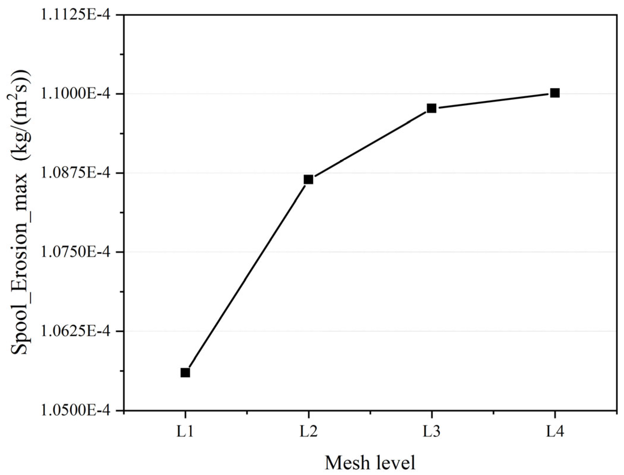
4.1. Mesh Independence

In this paper, the finite volume method was used to solve the calculation domain. The needle throttle was divided into numerous meshes, which are shown in Figure 2. Due to the presence of the mesh, there were discrete errors between the computed values calculated using the finite volume method and the computed exact solution. Theoretically, increasing the density of the mesh can reduce the value of the discrete error, but as the number of meshes increases, so does the consumption of computing resources.
Using different levels of mesh density and solving the mesh independence can save computing resources and improve computing efficiency with the calculation accuracy. Because the main concern of this paper is the size of the valve erosion rate, and the spool is often the most vulnerable part of the valve components, the maximum erosion rate of the spool was selected as the verification index.
As shown in Table 3, the mesh number level was first divided into L1-L4 levels, controlling the number of meshes mainly by controlling the local encryption size of the mesh, the surface mesh size, and the size of the body mesh. Table 3 shows the different quality parameters of the four-level meshes, and the quality of the four-level meshes met the requirements for calculation.
Figure 3 is the resulting diagram of mesh-independent verification, and it can be seen that the maximum erosion rate of the spool tends to converge with increasing mesh density. When the mesh level becomes L3, the calculation error has been reduced to within 1.5% compared with the L4-level mesh; increasing the number of meshes has a very weak effect on improving the calculation accuracy. This shows that using the L3-level mesh would allow us to obtain the calculation results more accurately while occupying fewer computing resources. Therefore, in this paper, the L3-level mesh was selected for calculation.

4.2. Flow Erosion Accuracy Validation

Before the start of the calculation, the physical and numerical models were verified by the results of the throttle erosion experiments studied by Zhu et al. [31].
As can be seen from Figure 4, the needle throttle CFD-DPM impulse model in this paper has a high agreement with the experiment, with an average relative error of less than 10%. Therefore, the physical and mathematical models used in this paper are considered accurate and reliable.

5. Result and Discussion

In this section, the flow field characteristics of the throttle valve are studied, then the particle trajectory is studied and the particle size and opening are analyzed, together with the effect of airflow on the particle flow rate, and the effect of particle mass flow on the erosion rate. Finally, the results of valve erosion are discussed. See Table 4 for specific example parameter settings.
In the DPM model, the airflow and the particle follow a bidirectionally coupled movement mode, that is, while the airflow affects the trajectory of the particle movement, it is also impacted by the particle movement.
In order to conduct the study more comprehensively, this section first analyzes the continuous-phase airflow field distribution with different openings.
Figure 5 is the cloud diagram of the velocity distribution of the wellhead-produced gas in the shale gas field when the particle size is 400 μm and the airflow velocity is 30 m/s. Due to the throttling effect, the velocity of the gas and particles increases significantly through the spool and the flow channel formed with the valve chamber, and the flow field with different openings after passing the flow channel is quite different. The smaller the valve opening, the higher the flow rate, and the later the separation point between the flow and the valve spool wall appears. When the valve opening degree is larger, the flow velocity of the airflow field is lower, and the distribution of the airflow velocity is more uniform.
It is worth noticing that the vortex distribution of the airflow in a valve chamber which has different opening degrees also has significant disparity. When the opening degree is 1/4, there is no vortex separation in the valve chamber and the airflow close to the core wall has an upward movement to the top of the valve chamber and then forms a vortex and a downward movement. With an increase in the opening degree, the separation of the airflow from the spool is more and more advanced. When the opening degree is 1, an obvious separation vortex is generated in the left chamber of the valve chamber.
Figure 6 shows the cloud map of the particle trajectory and the spool erosion rate at different opening degrees when the particle size is 400 μm and the airflow velocity is 30 m/s.
Particles under the influence of airflow have higher speeds coming into the valve from the upstream pipe; due to the complex flow channel inside the needle-type throttle valve, the particles inevitably collide with the valve parts which moved more complexly; when their kinetic energy decreases sharply after collision with a valve component, except for the part of the particles escaping from the outlet, the rest may be deposited in the downstream pipe and valve chambers.
When the valve opening decreases from a full opening to 1/4, the maximum erosion rate of the spool increases from 2.25 × 10 5 kg/(m2s) to 3.21 × 10 5 kg/(m2s). It is worth noticing that when the valve is fully open or the opening degree is large, due to the wide flow channel formed by the spool and the valve chamber, the particles and the spool rarely return to the upstream wall again after a collision. With a decrease in the valve opening to 1/4, the frequency and energy of the particles entering the upstream pipeline again after collision with the spool increases significantly, which is bound to cause some damage to the upstream pipeline.
In addition, due to the large energy loss, these particles after the secondary collision with the upstream pipeline have difficulty entering the valve chamber, and they settle downward and risk blocking the relatively narrow upstream pipeline under the action of gravity.

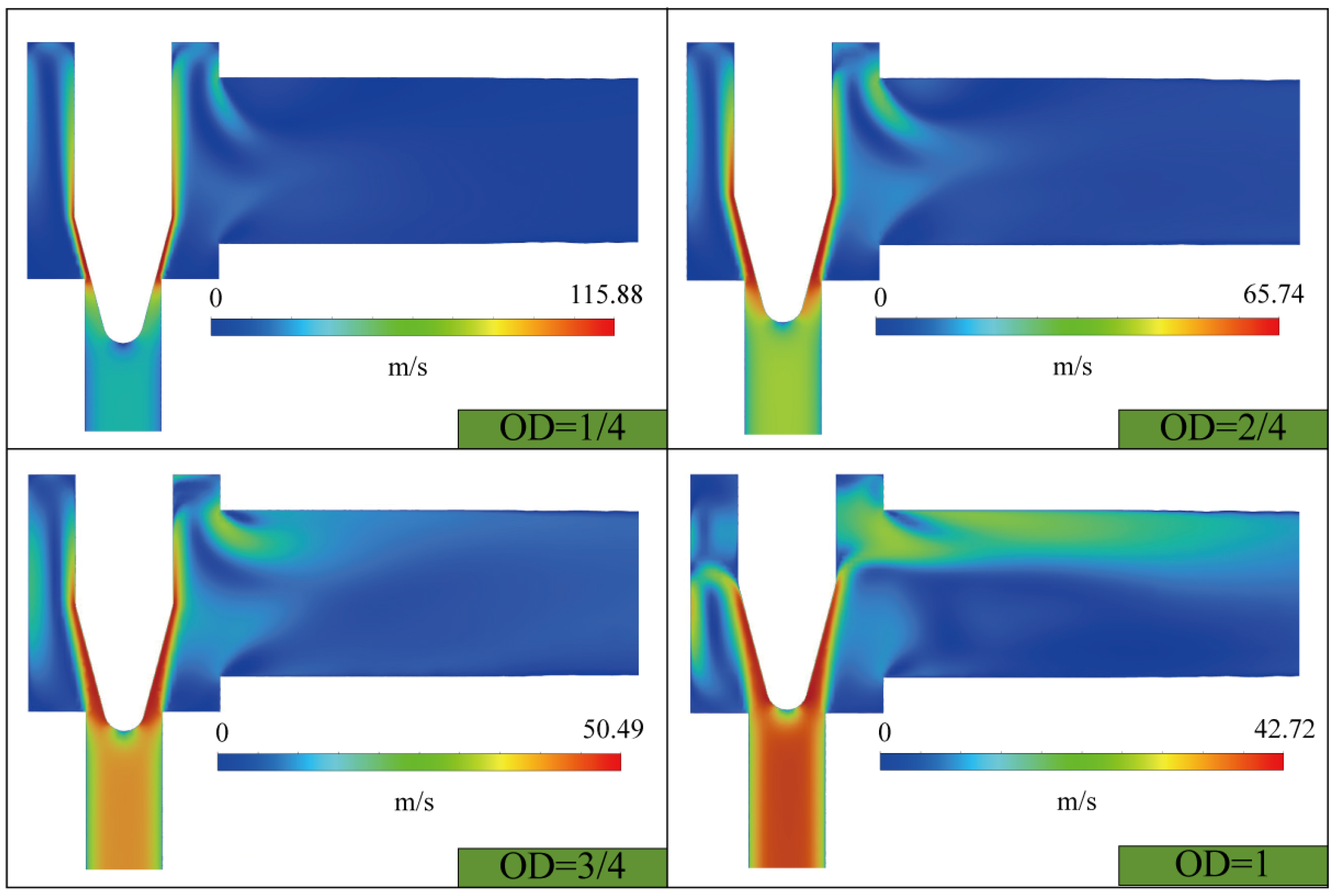
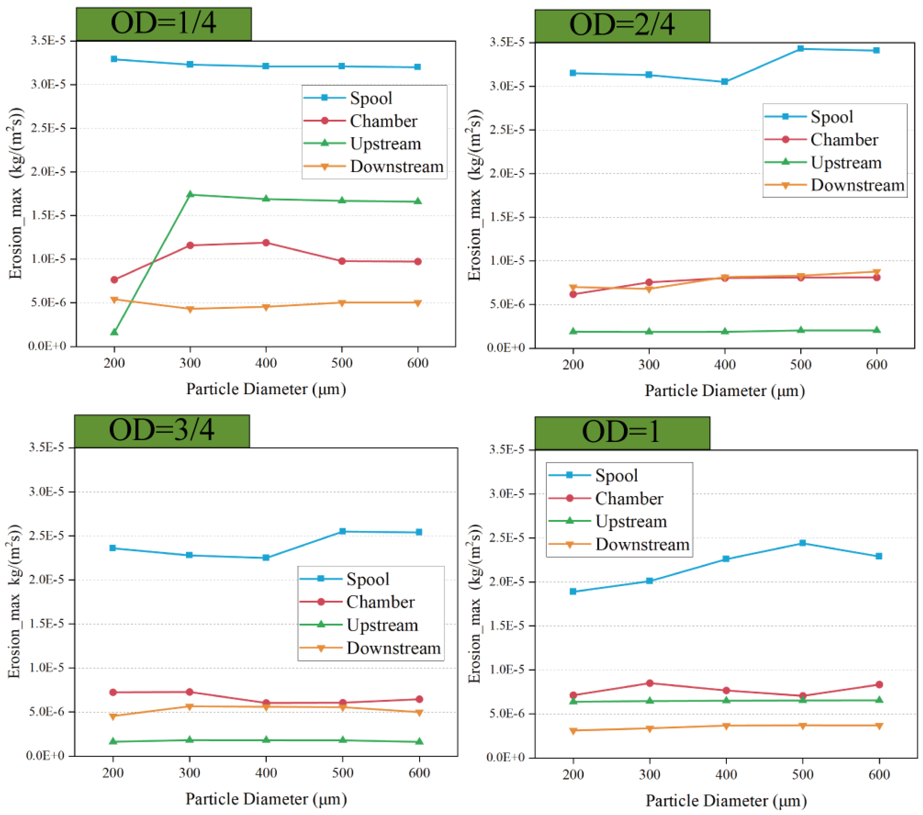
5.1. Effect of Particle Size and Opening on Erosion

According to previous studies [11,15,29], the maximum erosion rate of each valve component has the greatest impact on the life of the valve. This paper integrates the characteristics of the flow field, divides the needle-type throttle valve into four parts—namely, the upstream pipe, the valve chamber, the spool, and the downstream pipe—and studies the erosion rate of these four parts under different valve openings and particle sizes, separately. According to the actual working conditions in the field, this paper selects spherical particles as the object of study, and a particle diameter that is accordant with the particle size of the spherical particles.
Among the various parts of the valve, the most seriously eroded part is the spool. Figure 7 shows the erosion cloud of the spool under the working conditions of a VOD = 2/4 and a particle size of 200 μm. It can be seen that the most serious erosion area of the spool is located in the front of the Spool. For other conditions, see Figure 8.
The following Figure 8 is the contour diagram of the spool erosion rate. It can be seen from the dot plot that the maximum erosion rate of the spool is significantly ahead of several other components, no matter which working condition. When the valve opening gradually increases, the throttle effect gradually weakens, and the maximum erosion rate at the spool generally weakens, which provides a reference for the later maintenance of the spool. Moreover, it is not difficult to find that the erosion rate of the upstream pipeline increased greatly when the valve opening decreased to 1/4 and the particle size was greater than 200 μm.
From Figure 9, it is easy to find that, for the upstream pipeline, when the valve opening is reduced to 1/4 and the particle size is larger than 200 μm, the erosion rate experiences a large increase. Combined with Figure 6 and Figure 9, it can be seen that the frequency and energy of the particles entering the upstream pipeline again after collision with the valve spool under a 1/4 degree of opening increased significantly. When a particle’s size is small, its Stokes number is small and it is affected by the high speed of the continuous-phase fluid under a small degree of opening and, in the process of the particles entering the upstream pipeline again, the direction of its movement is greater than 90° with the direction of the movement of the airflow, and the airflow decelerates the effect of the particles very significantly.
When a particle’s size increases, its Stokes number also increases sharply, and the impact of gravity on the upstream pipeline also increases greatly. When the valve opening degree is greater than 2/4, the maximum erosion rate of the valve chamber is greater than the upstream and downstream pipes. From the integrated velocity field cloud maps and particle trajectories it can be found, in this working condition, that the airflow that is separated earlier from the spool wall carries particles to form a vortex in the valve chamber and has a dense collision with the wall of the valve chamber, which undoubtedly causes additional erosion damage to the valve chamber.
In addition, particles that collide with the wall of the valve chamber will lose a lot of kinetic energy and can easily deposit inside the valve chamber or fall into the upstream pipe.
The value of Erosion_max in Figure 9 is the erosion rate of the most serious parts of the valve components subject to erosion, and the data are derived from EDEM software (2021).

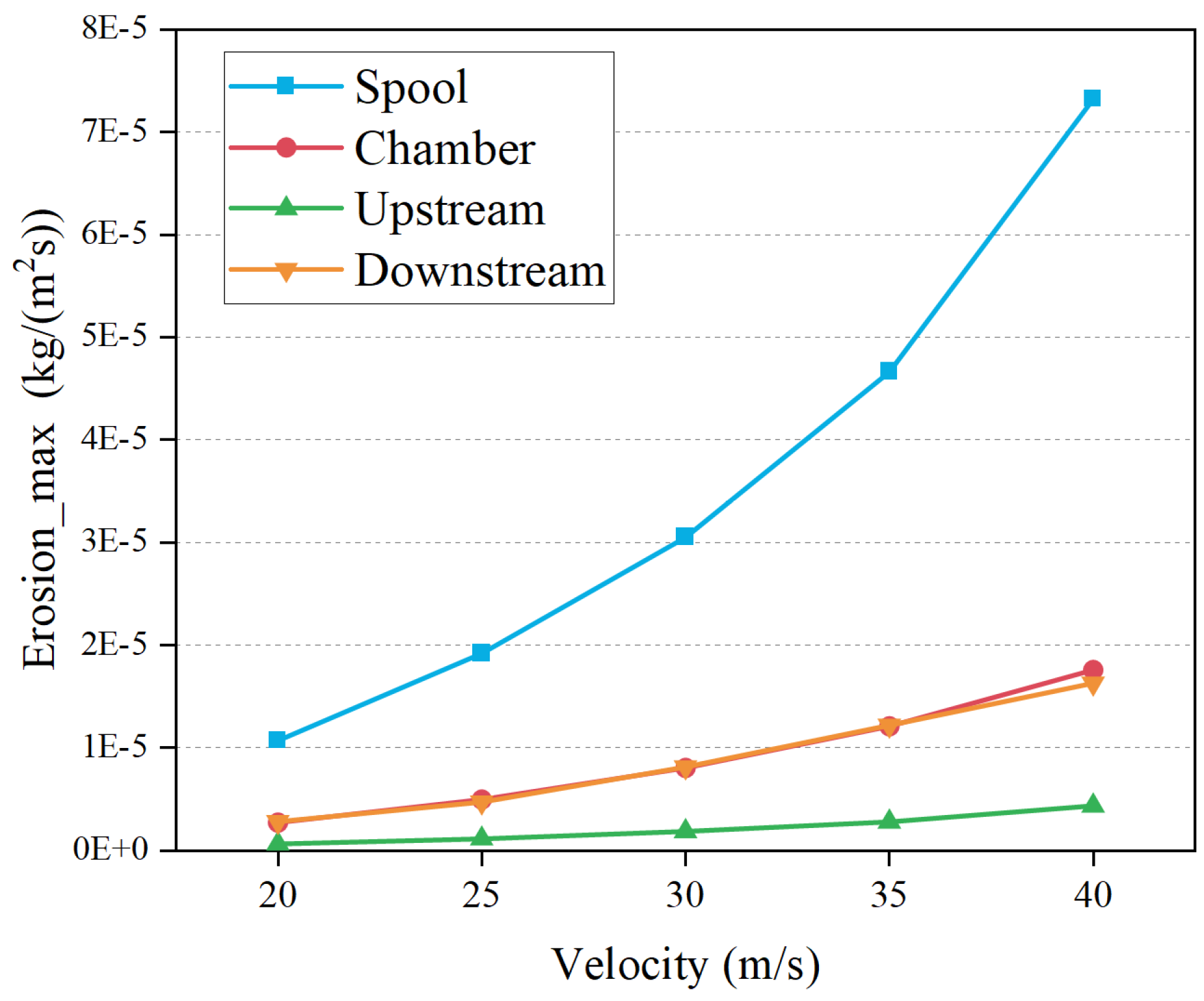
5.2. Effect of Flow Velocity on Erosion

In the actual production process in shale gas fields, the airflow velocity often changes. In this paper, the particle and airflow have the same inlet velocity and working conditions under an inlet velocity of 25~40 m/s are studied. The specific parameter settings can be seen in Table 4.
In Figure 10, as the initial speed of entering the valve increases, the maximum erosion rates of each component of the valve also gradually increase. But the valve core is undoubtedly the most seriously affected by the speed increase, and with the increase in the flow rate, the increasing trend becomes more obvious; at a flow rate of 40 m/s, the maximum erosion rate at the valve core exceeds 7 × 10 5 kg/(m2s) and the growth rates of the valve chamber and the downstream pipeline are almost consistent; however, when the speed is increased to 40 m/s, the maximum erosion rate of the downstream pipeline lags slightly behind the valve chamber, and the upstream pipelines are minimally affected by the increased flow rate.

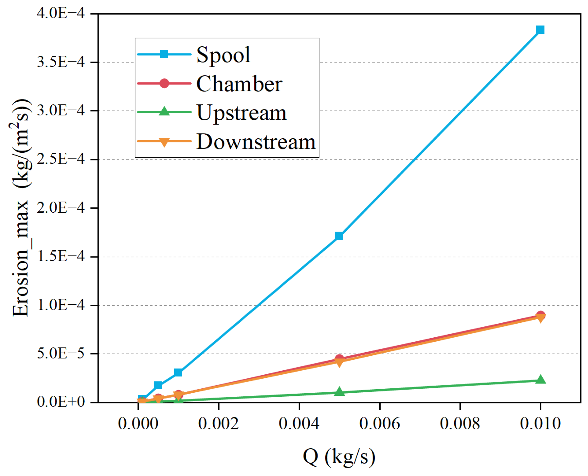
5.3. Effect of Particle Mass Flow Rate on Erosion

Considering the sediment content fluctuation of the gas produced in different shale gas fields, the particle mass flow (0~0.01kg/s) was studied.
The specific parameter settings can be seen in Table 4. As shown in Figure 11, below, with the increase in particle mass flow, the maximum erosion rate amount of the valve component also gradually increases. The trend is similar to the change in the amount of each component’s erosion after an increase in velocity. The spool remains the site that is most severely affected by the speed increase. This shows that inspections of the spool must be increased under a high mass flow rate and high flow rate.

6. Conclusions

The needle throttle is a key component of pneumatic conveying systems in shale gas fields, which are directly related to the safety production of gas fields. However, the high-speed solid particles carried by the gas produced from the wellhead can easily damage the key components of the valve. Due to the complex flow field of the needle throttle, it is difficult to explain the failure mechanism by traditional methods. Based on the CFD-DPM approach, this paper systematically studied the influence of particle size, particle mass flow, inlet speed, and valve opening on the erosion rate of various valve components, and drew the following conclusions:
  • Under all operating conditions, the erosion rate of the spool parts is greater than the other parts of the valve.
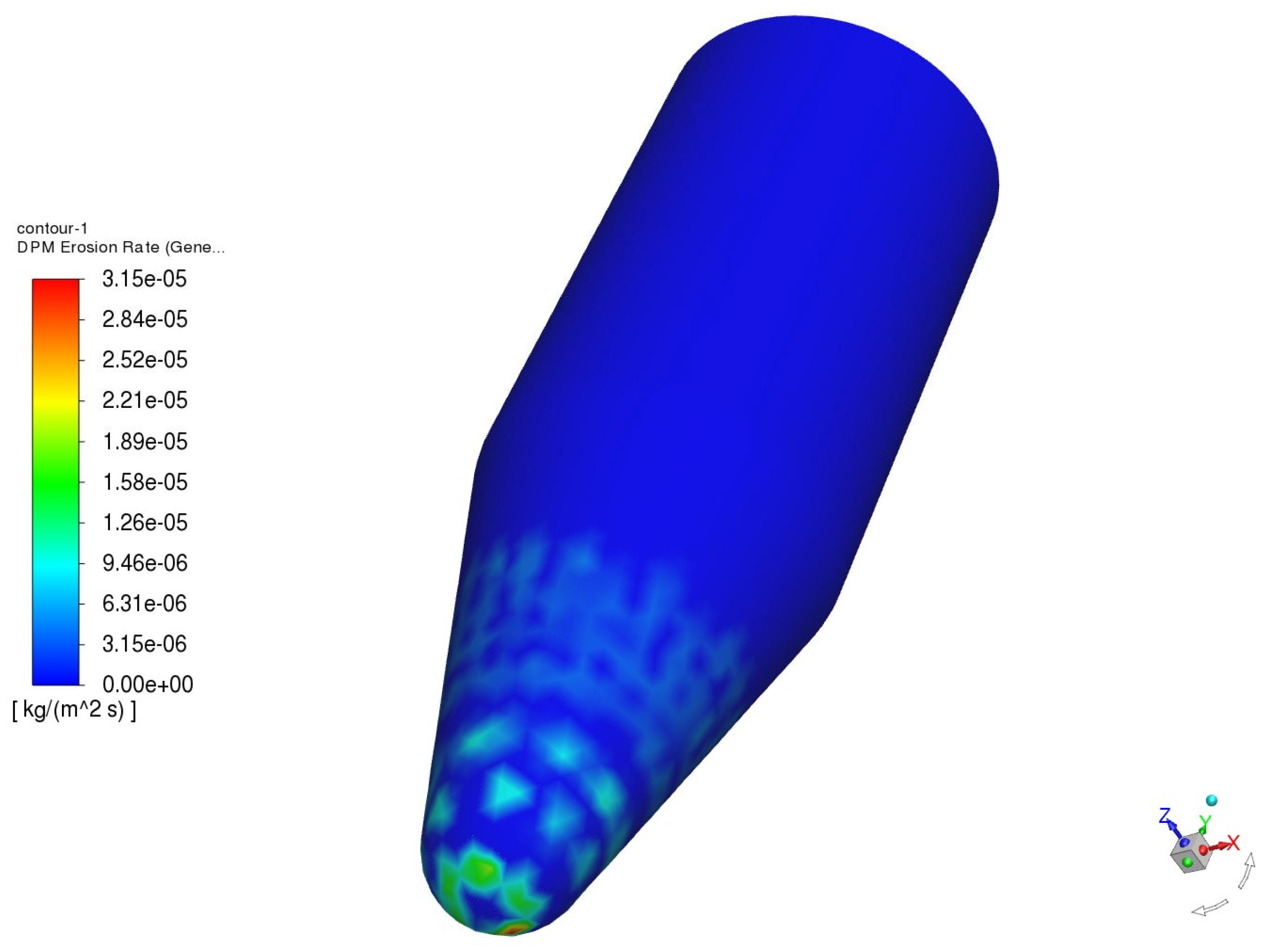
  • The area where the spool is vulnerable to erosion is located at the front of the spool, which provides a reference for the later maintenance of the spool.
  • At a 1/4 opening degree, the frequency and energy of the particles re-entering the upstream pipeline after collision with the spool increase significantly.
  • When the valve opening is greater than 2/4, the maximum erosion rate of the valve chamber is greater than the upstream and downstream pipes.
  • Some particles will fall into the upstream pipe after collision with the upstream pipe or the valve chamber, which can easily cause the blockage of upstream pipes with a narrow inner diameter.

Author Contributions

Conceptualization, Z.Z., W.W. and Z.W.; methodology, Z.Z., W.W. and Z.W.; software, Z.Z., X.W. and Y.W.; validation, Z.Z., X.W., X.C. and P.L.; formal analysis, Z.Z., W.W., Z.W. and X.W.; writing—original draft preparation, Z.Z., S.D. and X.C.; writing—review and editing, W.W., X.C., Z.W., S.D., Y.W. and X.W.; supervision, W.W. and Z.W.; funding acquisition, W.W. and Z.W. All authors have read and agreed to the published version of the manuscript.

Funding

This study is supported by the financial support of the Natural Science Foundation of Chongqing Municipality (CSTB2023NSCQ-MSX0050), Zhejiang New Talent Plan of Student’s Technology and Innovation program (No.2024R411B040), Science and Technology Project of Daishan County, Zhoushan City (No.202215), and the Zhejiang Provincial Natural Science Foundation of China under Grant No. LQ23E040004.

Institutional Review Board Statement

Not applicable.

Informed Consent Statement

Not applicable.

Data Availability Statement

Data are contained within the article.

Conflicts of Interest

Author Panfeng Li was employed by the company ENN (Zhou Shan) LNG Co., Ltd. The remaining authors declare that the research was conducted in the absence of any commercial or financial relationships that could be construed as a potential conflict of interest.

Nomenclature

aveAverage value
CFDComputational fluid dynamics
DPMDiscrete phase method
NTVNeedle throttle valve
ODOpening degree
A Particle   impact   angle ,   ( ° )
D p Particle diameter, (m)
E * Equivalent Young’s Modulus, (Pa)
F Force ,   ( N )
H v Vicker’s hardness, (GPa)
maxMaximum value
p Static pressure, (Pa)
R * Equivalent   radius ,   ( m )
R e r o s i o n kg/(m2s)
S t k Stokes number
u Flow   velocity ,   ( m / s )
ρ Density ,   ( k g / m 3 )
μ Molecular   viscosity   of   the   fluid ,   P a s
τ p Relaxation   time   of   the   particle ,   ( s )

References

  1. Hong, B.; Wang, C.; Zhang, K.; Lim, J.S.; Varbanov, P.S.; Jia, X.; Ji, M.; Tao, H.; Li, Z.; Wang, B. Carbon Emission Pinch Analysis for Shipping Fuel Planning Considering Multiple Period and Fuel Conversion Rates. J. Clean. Prod. 2023, 415, 137759. [Google Scholar] [CrossRef]
  2. Wen, K.; Jiao, J.; Zhao, K.; Yin, X.; Liu, Y.; Gong, J.; Li, C.; Hong, B. Rapid Transient Operation Control Method of Natural Gas Pipeline Networks Based on User Demand Prediction. Energy 2023, 264, 126093. [Google Scholar] [CrossRef]
  3. Liu, E.-B.; Huang, S.; Tian, D.-C.; Shi, L.-M.; Peng, S.-B.; Zheng, H. Experimental and Numerical Simulation Study on the Erosion Behavior of the Elbow of Gathering Pipeline in Shale Gas Field. Pet. Sci. 2024, 21, 1257–1274. [Google Scholar] [CrossRef]
  4. Zhou, J.; Lian, Z.H.; Wang, Y.H.; Liu, Y.; Wu, J. Failure Analysis and Structure Optimization of Throttle Valve Core. China Pet. Mach 2019, 47, 131–138. [Google Scholar]
  5. Hong, B.; Li, X.; Li, Y.; Li, Y.; Yu, Y.; Wang, Y.; Gong, J.; Ai, D. Numerical Simulation of Elbow Erosion in Shale Gas Fields under Gas-Solid Two-Phase Flow. Energies 2021, 14, 3804. [Google Scholar] [CrossRef]
  6. Mohammed, A.I.; Oyeneyin, B.; Atchison, B.; Njuguna, J. Casing Structural Integrity and Failure Modes in a Range of Well Types—A Review. J. Nat. Gas Sci. Eng. 2019, 68, 102898. [Google Scholar] [CrossRef]
  7. Fu, Y.; Wang, J. Experimental and Computational Failure Analysis of Flow Erosion on New Throttle in Gas Drilling. Pet. Coal 2015, 57, 246–252. [Google Scholar]
  8. Oka, Y.I.; Okamura, K.; Yoshida, T. Practical Estimation of Erosion Damage Caused by Solid Particle Impact: Part 1: Effects of Impact Parameters on a Predictive Equation. Wear 2005, 259, 95–101. [Google Scholar] [CrossRef]
  9. Forder, A.; Thew, M.; Harrison, D. A Numerical Investigation of Solid Particle Erosion Experienced within Oilfield Control Valves. Wear 1998, 216, 184–193. [Google Scholar] [CrossRef]
  10. Parsi, M.; Najmi, K.; Najafifard, F.; Hassani, S.; McLaury, B.S.; Shirazi, S.A. A Comprehensive Review of Solid Particle Erosion Modeling for Oil and Gas Wells and Pipelines Applications. J. Nat. Gas Sci. Eng. 2014, 21, 850–873. [Google Scholar] [CrossRef]
  11. Hong, B.; Li, Y.; Li, X.; Li, G.; Huang, A.; Ji, S.; Li, W.; Gong, J.; Guo, J. Experimental Investigation of Erosion Rate for Gas-Solid Two-Phase Flow in 304 Stainless/L245 Carbon Steel. Pet. Sci. 2022, 19, 1347–1360. [Google Scholar] [CrossRef]
  12. Deng, K.; Zhou, N.; Lin, Y.; Cheng, J.; Bing, L.; Jing, Z. Experimental and Numerical Study on the High-Speed Gas-Solid Nozzle Erosion of Choke Manifold Material in High Pressure and High Production Gas Well. Powder Technol. 2024, 438, 119628. [Google Scholar] [CrossRef]
  13. Wei, S.S.; Lee, M.C.; Chien, Y.H.; Chou, T.H.; Wu, J.S. Experimental Investigation of the Effect of Nozzle Throat Diameter on the Performance of a Hybrid Rocket Motor with Swirling Injection of High-Concentration Hydrogen Peroxide. Acta Astronaut. 2019, 164, 334–344. [Google Scholar] [CrossRef]
  14. Hong, B.; Li, Y.; Li, X.; Ji, S.; Yu, Y.; Fan, D.; Qian, Y.; Guo, J.; Gong, J. Numerical Simulation of Gas-Solid Two-Phase Erosion for Elbow and Tee Pipe in Gas Field. Energies 2021, 14, 6609. [Google Scholar] [CrossRef]
  15. Hong, B.; Li, Y.; Li, Y.; Gong, J.; Yu, Y.; Huang, A.; Li, X. Numerical Simulation of Solid Particle Erosion in the Gas-Liquid Flow of Key Pipe Fittings in Shale Gas Fields. Case Stud. Therm. Eng. 2023, 42, 102742. [Google Scholar] [CrossRef]
  16. Ou, G.; Cao, X.; Wang, C.; Duan, A.; Jin, H. CFD-DEM-Based Numerical Simulation of Erosion Characteristic of Multistage Pressure Relief String Regulating Valve. J. Appl. Fluid Mech. 2022, 15, 999–1015. [Google Scholar] [CrossRef]
  17. Perera, P.; Hayward, K.; Guzzomi, F.; Vafadar, A. Erosion Wear Characterisation of an Open Ductile Iron Butterfly Valve Subjected to Aluminium Oxide Particle Slurry Flow. Tribol. Int. 2024, 191, 109199. [Google Scholar] [CrossRef]
  18. Hu, G.; Zhang, P.; Wang, G.; Zhu, H.; Li, Q.; Zhao, S.; Qiao, K.; Wang, T. Performance Study of Erosion Resistance on Throttle Valve of Managed Pressure Drilling. J. Pet. Sci. Eng. 2017, 156, 29–40. [Google Scholar] [CrossRef]
  19. Wang, G.R.; Chu, F.; Tao, S.Y.; Jiang, L.; Zhu, H. Optimization Design for Throttle Valve of Managed Pressure Drilling Based on CFD Erosion Simulation and Response Surface Methodology. Wear 2015, 338–339, 114–121. [Google Scholar] [CrossRef]
  20. Zhao, Y.; Wang, W.; Sun, F.; Yu, Y.; Zhou, W.; Tan, H. Simulation and Structure Optimization of WC–Co Cemented Carbide Cage-Sleeve Type Throttle Valve Core Erosion. Trans. Indian Inst. Met. 2024, 77, 69–79. [Google Scholar] [CrossRef]
  21. Guo, L.; Wang, Y.; Xu, X.; Gao, H.; Yang, H.; Han, G. Study on the Erosion of Choke Valves in High-Pressure, High-Temperature Gas Wells. Processes 2022, 10, 2139. [Google Scholar] [CrossRef]
  22. Ma, H.; Jiang, Y.; Yin, Q.; Zhang, F.; Chen, S.; Lv, Y.; Lei, G. Investigation on Erosion Resistance of Downhole Throttle with Ultra-High Pressure. IOP Conf. Ser. Earth Environ. Sci. 2020, 453, 12059. [Google Scholar] [CrossRef]
  23. Rong, Z.; Zhao, C.; Zihan, Z.; Qiyu, H.; Pengbo, H.; Kuan, S. Simulation and Optimization Design of Tubular Throttle Valve Based on SolidWorks. Int. J. Front. Eng. Technol. 2023, 5, 050602. [Google Scholar] [CrossRef]
  24. Tarasevych, Y.; Sovenko, N. Modelling the Influence of Cylindrical Throttle Erosion Wear on Characteristics of Automatic Balancing Device. Tribologia 2019, 3, 107–113. [Google Scholar] [CrossRef]
  25. Hutchings, I.M.; Winter, R.E.; Field, J.E.; Tabor, D. Solid Particle Erosion of Metals: The Removal of Surface Material by Spherical Projectiles. Proc. R. Soc. London. A. Math. Phys. Sci. 1997, 348, 379–392. [Google Scholar] [CrossRef]
  26. Levy, A.V.; Chik, P. The Effects of Erodent Composition and Shape on the Erosion of Steel. Wear 1983, 89, 151–162. [Google Scholar] [CrossRef]
  27. Bruno, A.D.; Batkhin, A.B. Survey of Eight Modern Methods of Hamiltonian Mechanics. Axioms 2021, 10, 293. [Google Scholar] [CrossRef]
  28. Wu, Z.; Wang, C.; Lang, R.; Li, Y.; Hong, B. The Distribution of Components in Hydrogen-Blended Pipelines under Different Gas Stream Injection Pattern. Fuel 2024, 375, 132577. [Google Scholar] [CrossRef]
  29. Lin, Z.; Sun, X.; Yu, T.; Zhang, Y.; Li, Y.; Zhu, Z. Gas–solid Two-Phase Flow and Erosion Calculation of Gate Valve Based on the CFD-DEM Model. Powder Technol. 2020, 366, 395–407. [Google Scholar] [CrossRef]
  30. Gosman, A.D.; Loannides, E. Aspects of Computer Simulation of Liquid-Fueled Combustors. J. Energy 1983, 7, 482–490. [Google Scholar] [CrossRef]
  31. Zhu, H.; Pan, Q.; Zhang, W.; Feng, G.; Li, X. CFD Simulations of Flow Erosion and Flow-Induced Deformation of Needle Valve: Effects of Operation, Structure and Fluid Parameters. Nucl. Eng. Des. 2014, 273, 396–411. [Google Scholar] [CrossRef]
Figure 1. Valve 3D component diagram.
Coatings 15 00248 g001
Figure 2. Meshing (VOD = 0.5). (a) Features of surface mesh and cross-section of upstream pipeline. (b) Vertical section of spool and chamber.
Coatings 15 00248 g002
Figure 3. Mesh independence validation.
Coatings 15 00248 g003
Figure 4. Comparison of CFD and experimental results.
Coatings 15 00248 g004
Figure 5. Speed field cloud diagram.
Coatings 15 00248 g005
Figure 6. Cloud diagram of particle trajectory and spool erosion rate at different opening degrees.
Coatings 15 00248 g006
Figure 7. The contour diagram of the spool erosion rate under the working condition of VOD = 2/4 and particle size of 200 μm.
Coatings 15 00248 g007
Figure 8. The contour diagrams of the spool erosion rate.
Coatings 15 00248 g008
Figure 9. Diagrams of erosion rate of each valve component under each opening degree and particle size.
Coatings 15 00248 g009
Figure 10. The erosion rate diagram for each part of the valve under different flow rates.
Coatings 15 00248 g010
Figure 11. The erosion rate diagram for each part of the valve under different particle mass flow rates.
Coatings 15 00248 g011
Table 1. Key parameters of physical model.
UnitGas StreamParticleValve
Material CH4SandSteel
Density   ( ρ )kg/m30.667928008030
Dynamic   Viscosity   ( ν ) P a s 1.087 × 10⁻⁵
Table 2. The parameters of f ( γ ) [15].
PointAngleValue
100
2200.8
3301
4450.5
5900.4
Table 3. The quantity and quality parameters of mesh under different levels.
Mesh LevelBoi MeshSurface MeshMesh QuantityMinimum Orthogonality QualityMaximum Aspect Ratio
L133/24242,4610.3059.6
L22.52.5/20368,2190.3437.1
L322/16670,2240.3834.2
L41.51.5/121,295,6200.4029.7
Table 4. Calculation parameter setting table.
CaseOD D p (μm) u g a s (m/s) Q m p (kg/s)
11/4, 1/2, 3/4, 1-300
21/4200, 300, 400, 500, 60030 1 × 10 3
31/2200, 300, 400, 500, 60030 1 × 10 3
43/4200, 300, 400, 500, 60030 1 × 10 3
51200, 300, 400, 500, 60030 1 × 10 3
61/240020, 25, 35, 40 1 × 10 3
71/240030 1 × 10 2 ,   5 × 10 3 ,   5 × 10 4 ,   1 × 10 4
Disclaimer/Publisher’s Note: The statements, opinions and data contained in all publications are solely those of the individual author(s) and contributor(s) and not of MDPI and/or the editor(s). MDPI and/or the editor(s) disclaim responsibility for any injury to people or property resulting from any ideas, methods, instructions or products referred to in the content.

