Article

Microstructure and Mechanical Properties of a Novel Lightweight and Heat-Resistant Al-3.0Ce-0.9Ca-1.9Mn-1.2Zr Alloy Fabricated by Selective Laser Melting

1
School of Materials Science and Engineering, Anhui Polytechnic University, Wuhu 241000, China
2
The Jointly Established Key Laboratory of Additive Manufacturing (3D Printing) Discipline, Anhui Polytechnic University, Wuhu 241000, China
3
Anhui Chungu 3D Printing Intelligent Equipment Industrial Technology Research Institute Co., Ltd., Wuhu 241000, China
4
Wuhu Yongda Tech. Co., Ltd., Wuhu 241000, China
5
Modern Technology Center, Anhui Polytechnic University, Wuhu 241000, China
6
Anhui Shengerwo Intelligent Equipment Co., Ltd., Wuhu 241000, China
7
CNPC Powder China Ltd., Chuzhou 239000, China
*
Author to whom correspondence should be addressed.
Coatings 2025, 15(2), 247; https://doi.org/10.3390/coatings15020247
Submission received: 20 January 2025 / Revised: 12 February 2025 / Accepted: 13 February 2025 / Published: 19 February 2025
(This article belongs to the Special Issue Structural, Mechanical and Tribological Properties of Hard Coatings)

Abstract

:
This article discusses the microstructure and mechanical properties of an Al-3.0Ce-0.9Ca-1.9Mn-1.2Zr alloy produced by selective laser melting (SLM) technology. The new alloy leverages the excellent heat resistance of Al-Ce alloys, incorporating Ca to lower both the cost and density, while the addition of Mn and Zr enhances formability and provides additional precipitation strengthening. Through the optimization of heat-treatment parameters, the optimal conditions were determined, with an annealing temperature of 375 °C and a holding time of 8 h. After annealing, the alloy’s tensile strength increased from 333 MPa to 412 MPa, yield strength rose from 246 MPa to 359 MPa, and elongation decreased from 24.4% to 16.4%. Compared to the as-built state, tensile strength and yield strength increased by 23.6% and 46.1%, respectively, while elongation decreased by 32.7%. The alloy demonstrates excellent heat resistance, with yield strengths at test temperatures of 200 °C, 250 °C, 300 °C, and 350 °C at 167 ± 17 MPa, 144 ± 8 MPa, 84 ± 4 MPa, and 57 ± 5 MPa, respectively. Notably, alloying imparts a degree of superplasticity, likely due to the synergistic effects of the Ca, Mn, and Zr elements.

1. Introduction

Compared with traditional manufacturing processes, selective laser melting (SLM) technology offers advantages in both manufacturing and metallurgy, including near-net shaping and rapid solidification, making it capable of producing high-strength, complex-shaped parts [1]. It also meets the demands of various application fields. Research on stainless steel [2,3,4], titanium alloys [5,6,7], and aluminum alloys [8,9,10,11] has been relatively extensive. Aluminum alloys, known for their excellent mechanical properties and corrosion resistance, are widely used in aerospace, automobile engine, and other industries [12,13,14,15]. A well-designed process can significantly reduce the residual stress and anisotropy in SLM-formed parts [16]. Residual thermal stress can also be alleviated through various heat-treatment methods [17,18], such as reducing porosity and cracks using hot isostatic pressing (HIP) [19]. Compared to traditional Al-Si, Al-Mg, and Al-Cu alloys, Al-Ce alloys exhibit superior high-temperature mechanical properties [20,21,22]. SLM-formed Al alloys generally offer higher strength than those produced by traditional casting methods. However, the anisotropy of SLM-formed Al-3.0Ce-0.9Ca-1.9Mn-1.2Zr alloys remains significant. In severe cases, it can cause the alloy to fracture along the direction of poor mechanical properties in anisotropy, resulting in a certain degree of loss, and the room temperature tensile properties of these alloys often do not meet the increasing demands for advanced performance. The annealing process can promote the precipitation of the supersaturated Ce element from the α-Al matrix, forming the Al11Ce3 strengthening phase. This enhances the room temperature tensile properties of the alloy and reduces material anisotropy.
The eutectic composition of the Al-Ce binary system is 10% Ce by mass, with a eutectic temperature of 640 °C [23]. During solidification, eutectic reactions occur, forming the α-Al phase and the intermetallic compound Al11Ce3 phase. The Al11Ce3 phase has an orthorhombic body-centered lattice, with lattice constants a, b, and c of 0.4395 nm, 1.3025 nm, and 1.0092 nm, respectively. This compound has a high melting point and excellent thermal stability, and its phase stability at high temperatures is much higher than that of secondary phases in conventional commercial aluminum alloys, such as the eutectic Si phase in Al-Si alloys or the θ (Al2Cu) phase in Al-Cu alloys. According to SIMS et al. [24], the as-cast Al-Ce binary eutectic alloy exhibited excellent thermal stability, retaining 80% of its room temperature mechanical properties even at 240 °C. Liu et al. [25] studied a cast Al-12.5% Ce alloy, in which the eutectic Al11Ce3 strengthening phase exhibited a strip-like morphology of 200–400 nm and demonstrated good thermal stability. After extended aging treatment, the morphology remained unchanged, and no significant hardness reduction was observed even after 12 weeks of aging at 400 °C. Although Al-Ce alloys show good high-temperature stability, their room temperature performance is relatively poor. This is due to the coarsening of the eutectic structure formed directly during the solidification reaction in the liquid phase, which weakens the strengthening effect of the Al11Ce3 eutectic. The contribution to strength via the Orowan strengthening mechanism is therefore limited. Furthermore, the eutectic point of Al-Ce alloys is 12 wt.% Ce. When the alloy solidifies directly from liquid to eutectic, the coherency with the Al matrix is poor, resulting in a weak strengthening effect. Therefore, to enhance the plastic processing capability of Al-Ce alloy and expand its application scenarios, it is necessary to find an alloying element that can reduce the amount of Ce and improve the specific strength of the alloy.
Al-Ca alloys exhibit good formability and mechanical properties. Research has shown that the ultra-fine eutectic structure formed by Ca and Al significantly improves the casting performance of these alloys. When the Ca content approaches the eutectic point of 8 wt.%, a large amount of Ca-rich primary phase is formed. Su et al. [26] enhanced the room temperature formability of as-cast Al-5Cu-0.5Mn by three times by adding low concentrations of Ca (0.5 wt.% and 1 wt.%) to the Al-5Cu-0.5Mn alloy. T.K. Sviridova et al. [27] analyzed the structure and properties of intermetallic compounds in Al-Ca-Cu ternary system alloys. In the ternary alloy system, Al is in an equilibrium state, which is linked to the phase field of the binary alloy (Al) + Al4 (Ca,Cu) and the quasi-binary (Al) + Al27Ca3Cu7 section. This alloy is considered a promising basis for a new type of natural composite Al-based material. Belov et al. [28] studied the microstructure, phase composition, and hardness of Al-6Cu-2Mn alloys containing 1–4 wt.% Ca after high-temperature annealing. The results showed that the microstructure consisted of a fine eutectic structure containing Ca and the Al20Cu2Mn3 phase, with a size of about 100 nm, which helped prevent recrystallization and maintained a fine grain structure. T.K. Akopyan et al. [29] designed a novel quaternary eutectic Al-Cu-Ca-Si system utilizing precipitation hardening. Their study revealed that Al-5Cu-Ca-Si had higher thermal stability compared to Al-5Cu. Du et al. [30] modified an Al-Mg-Sc alloy with Ca, and the modified alloy exhibited excellent high-temperature performance and good thermal stability even at 300 °C. P.K. Shurkin et al. [31] prepared an Al-Ca-Ni-Mn alloy using laser powder-bed melting technology and annealed the samples at temperatures between 200 °C and 400 °C for 3 h. The results showed that after annealing at 300 °C for 3 h, the microhardness of the alloy decreased from 200 HV to 161 HV, with softening and the growth of the primary phase up to 800 nm and eutectic phases up to 80 nm. The SLM (selective laser melting) process, characterized by rapid melting and solidification, can significantly refine the microstructure of alloys.
This study investigates the microstructure and properties of Al-Ce alloys with added Ca under rapid solidification. Polarized optical microscopy (OM), electron backscatter diffraction (EBSD) analysis, and mechanical property testing were used to examine the grain size and mechanical properties of SLM-formed Al-3.0Ce-0.9Ca-1.9Mn-1.2Zr alloys. The aim is to provide a reference for the design and application of heat-treatment processes for SLM-formed Al-Ce alloys.

2. Experimental Procedure

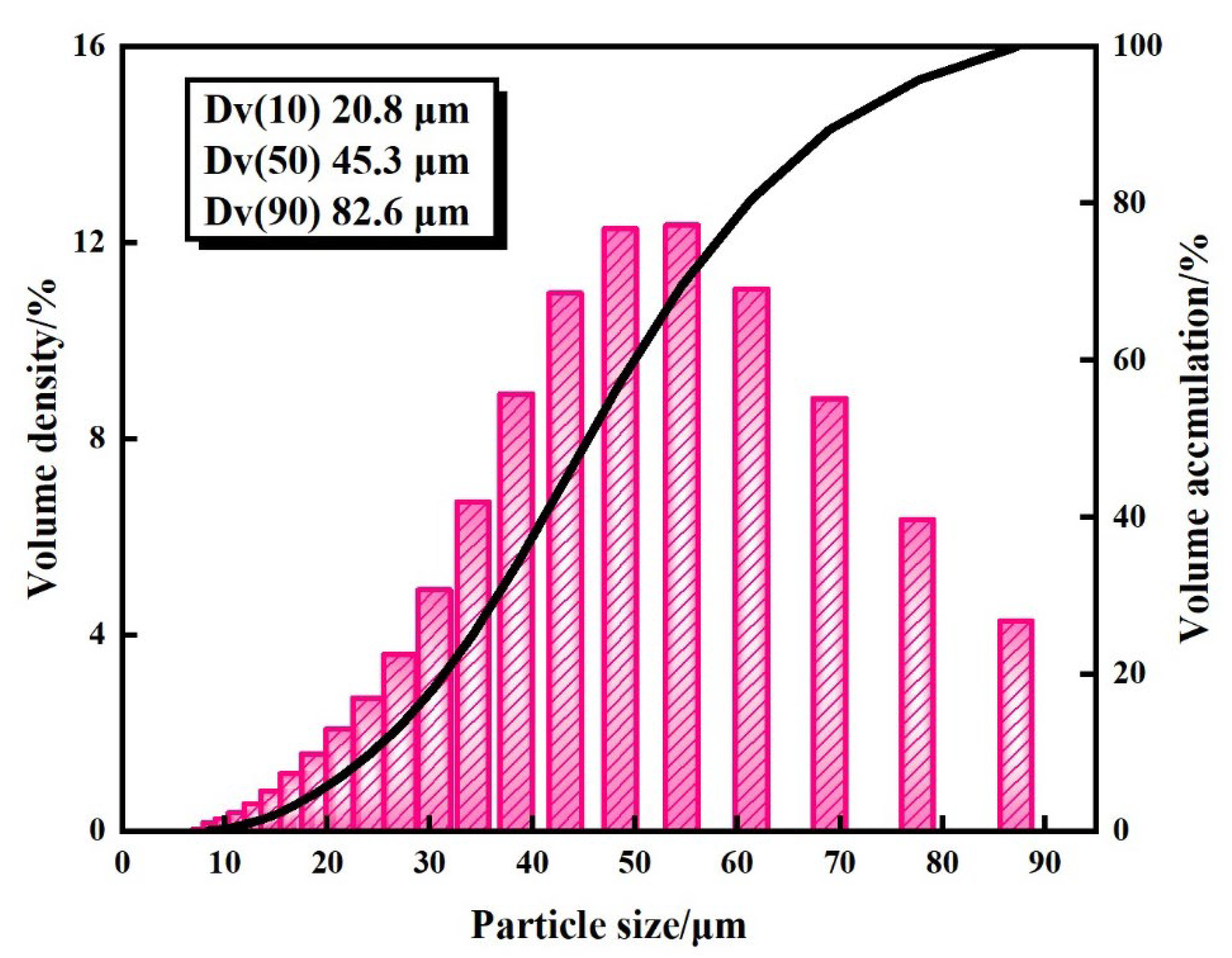
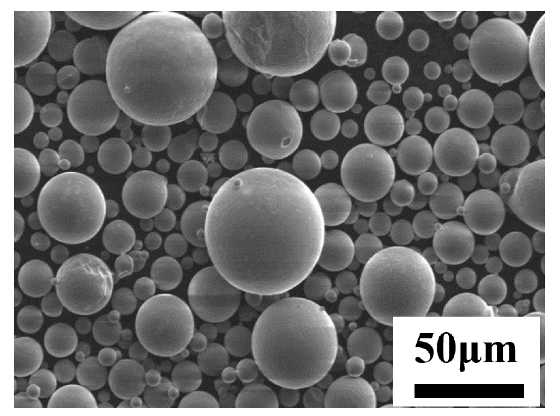
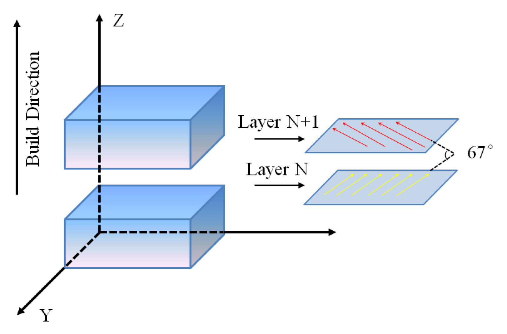
Materials and Processing

The Al-3.0Ce-0.9Ca-1.9Mn-1.2Zr alloy powder used in this study was prepared by the atomization method provided by Zhongti New Materials Co., Ltd. The results of the particle size measurement of the Al-3.0Ce-0.9Ca-1.9Mn-1.2Zr alloy powder are shown in Figure 1. As seen in Figure 1, the overall particle size of the powder follows a normal distribution, with a size range between 10 and 90 μm. The particle size distributions Dv (10), Dv (50), and Dv (90) of the alloy powders at different contents are 20.8 μm, 45.3 μm, and 82.6 μm, respectively. Appropriate powder particle size helps to avoid various metallurgical defects such as porosity and lack of fusion [32]. In SLM, the layer-by-layer accumulation and stacking process means that the quality of each powder layer directly influences the quality of the final formed part. Uneven powder layers can result in melting defects in the powder. The impurity content in the powder used in this study is relatively low, and the particle size distribution follows a normal distribution, meeting the requirements for the SLM process. The alloy powder also exhibits high sphericity, as shown in Figure 2. The size of the powder particles can impact the porosity and microstructure of SLM-formed samples. The X-ray diffraction (XRD) results of the powder are shown in Figure 3. Due to the solid solution of elements such as Ce, Ca, Mn, and Zr in the α-Al matrix, the interplanar spacing of the α-Al matrix increases, leading to a leftward shift in the diffraction peak. The composition of each element in the alloy is shown in Table 1.
The SLM process was carried out using the German EOS-EOSINT-M-280 SLM printer (EOS, Munich, Germany), which is equipped with a Yb-fiber laser emitter featuring a spot diameter of 80 μm and a maximum forming size of 250 mm × 250 mm × 250 mm. The process parameters for the SLM technology are as follows: laser power of 380 W, scanning speed of 1400 mm/s, scanning spacing of 0.13 mm, printing layer thickness of 0.04 mm, and an interlayer deflection angle of 67°. The scanning strategy for the SLM process is shown in Figure 4. Preparation of Al-3.0Ce-0.9Ca-1.9Mn-1.2Zr cylindrical alloy solid with a bottom radius of 15 mm and a height of 11 mm uses the SLM process parameters described above. The Al-3.0Ce-0.9Ca-1.9Mn-1.2Zr alloy formed by SLM was polished to a smooth surface, and the microstructure of the molten pool in the formed alloy was observed using electrolytic polishing and anode coating. The Smartlab SE X-ray diffraction instrument (XRD) (Rigaku, Tokyo, Japan) was used for phase analysis of Al-3.0Ce-0.9Ca-1.9Mn-1.2Zr alloy powder and alloy samples. The diffraction angle (2θ) range was 10–90°, and the scanning rate was 3°/min. Electron backscatter diffraction (EBSD) (Oxford Instruments, Oxford, UK) was integrated into an OXFORD CNANO field emission scanning electron microscope (FESEM), which was used to analyze the grain size, morphology, and microstructure of the sample. The EBSD scanning step size was 0.25 μm. For EBSD sample preparation, mechanical polishing was first performed, followed by electrolytic polishing in a solution of 10 ml HClO4 + 90 ml C2H5OH. The polishing voltage was set at 15 V, and the polishing time was 20 seconds. Finally, AZtecCrystal 2.1 software was used for post-processing the data obtained from the EBSD measurements. To further improve the mechanical properties of the alloy and eliminate residual stresses, annealing processes with different parameters were carried out on the alloy. The alloy sample was annealed using a Kejing KSL-1100X-S muffle furnace (Kejing, Hefei, China), with a heating rate of 10 °C/min. When the temperature reached the pre-determined temperature, the sample was lowered and placed in the muffle furnace for heating. The cooling method was water cooling. The hardness test used a TMVS-1 Vickers hardness tester with a loading force of 500 g and a loading time of 10 s. Tensile tests of Al-3.0Ce-0.9Ca-1.9Mn-1.2Zr alloy specimens, both in the printed and annealed states, were conducted at a rate of 0.5 mm/min using the SHIMADZU AGS-1KNJ testing machine (SHIMADZU, Tokyo, Japan) incorporating digital image correlation (DIC) (Nanjing, China). For full-field strain mapping, the optical extensometer equipment model used was the Ruize RVX-112 (Nanjing, China). The standard length of the room temperature tensile test specimen was 9.7 mm. Prior to testing, the SLM-formed specimens were cut into sheets using a wire cutting device, and the machined surfaces were polished to a flat, bright finish. The dimensions of the tensile test specimens are shown in Figure 5.

3. Results and Discussion

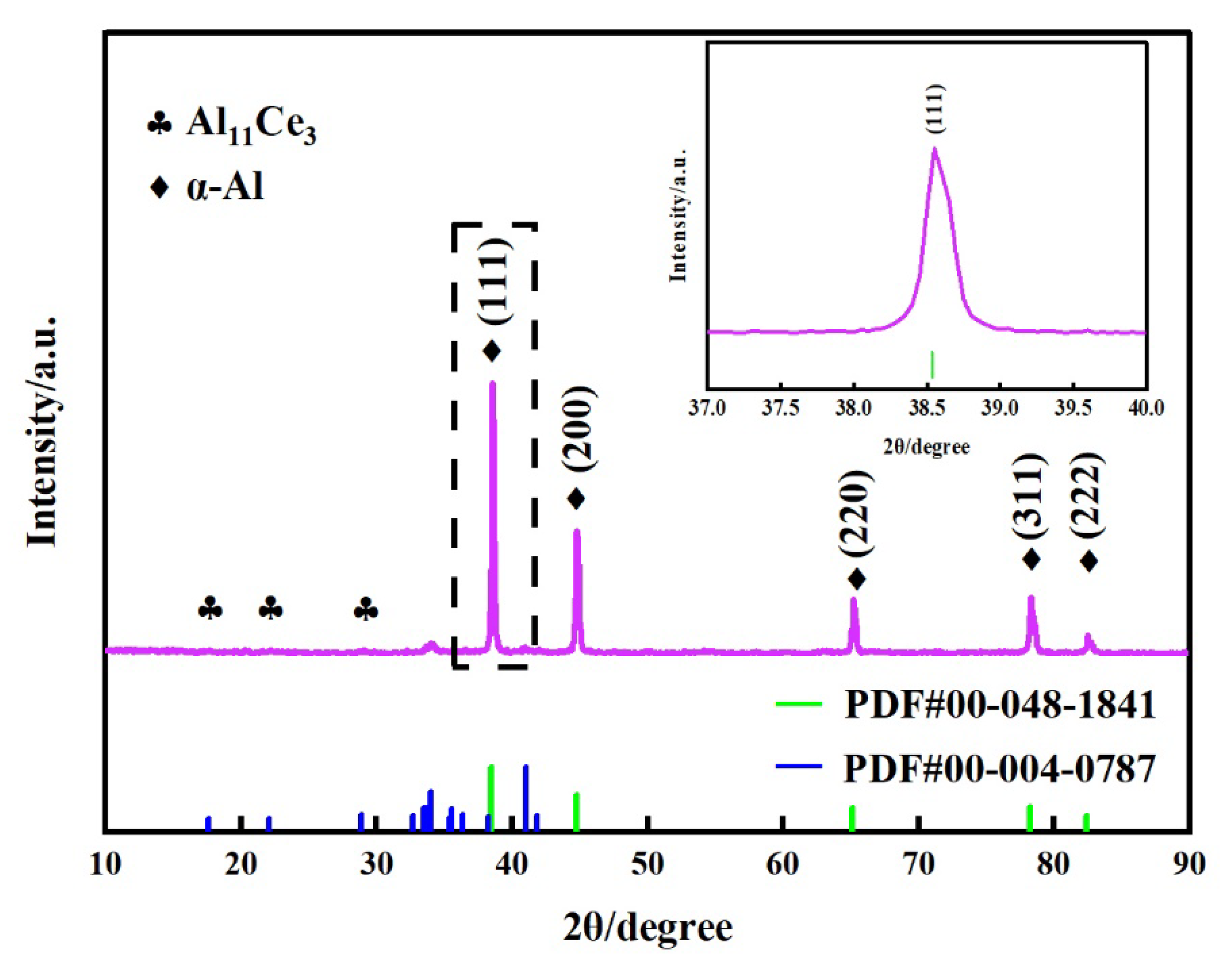
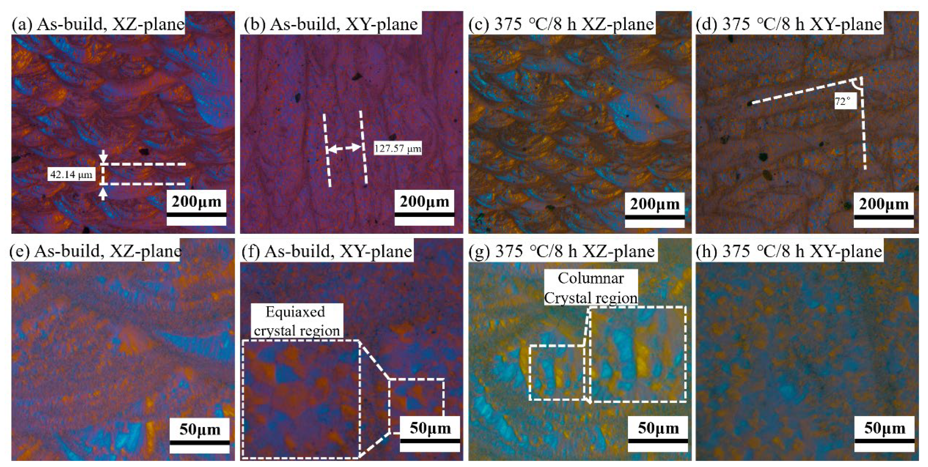
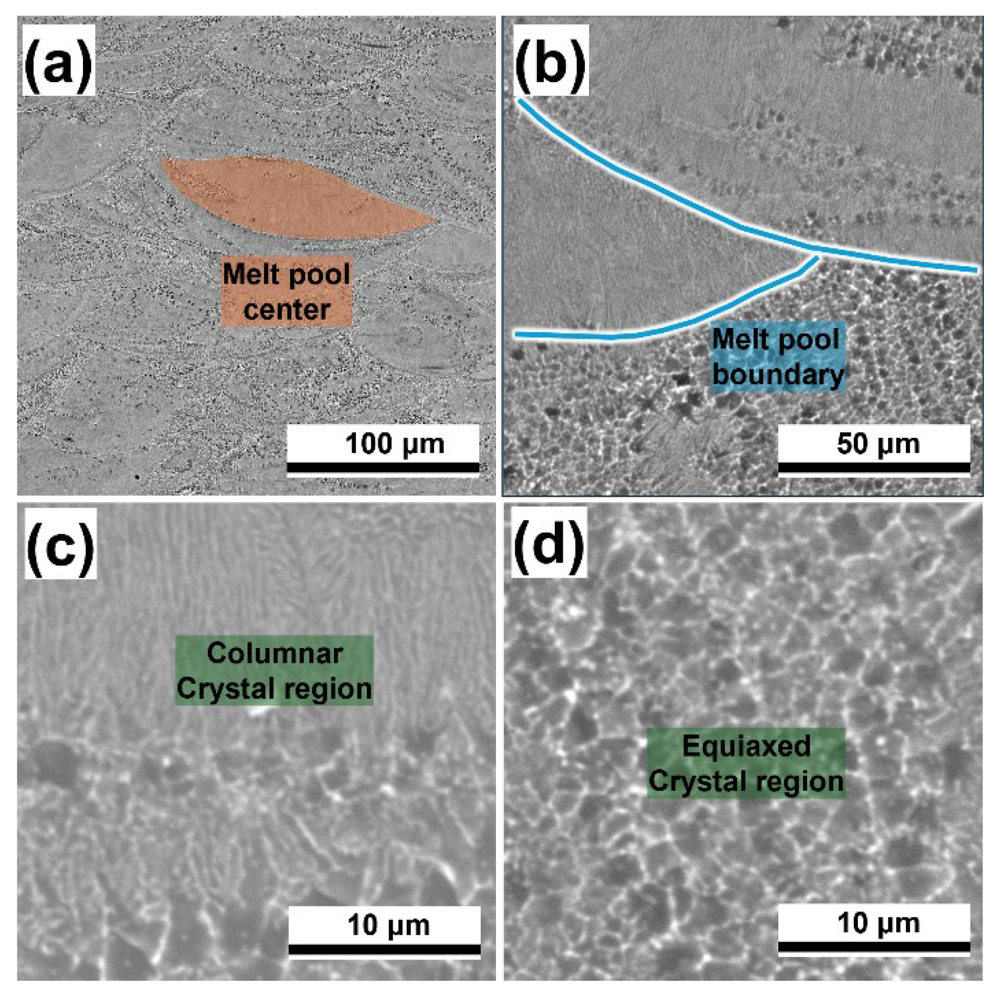
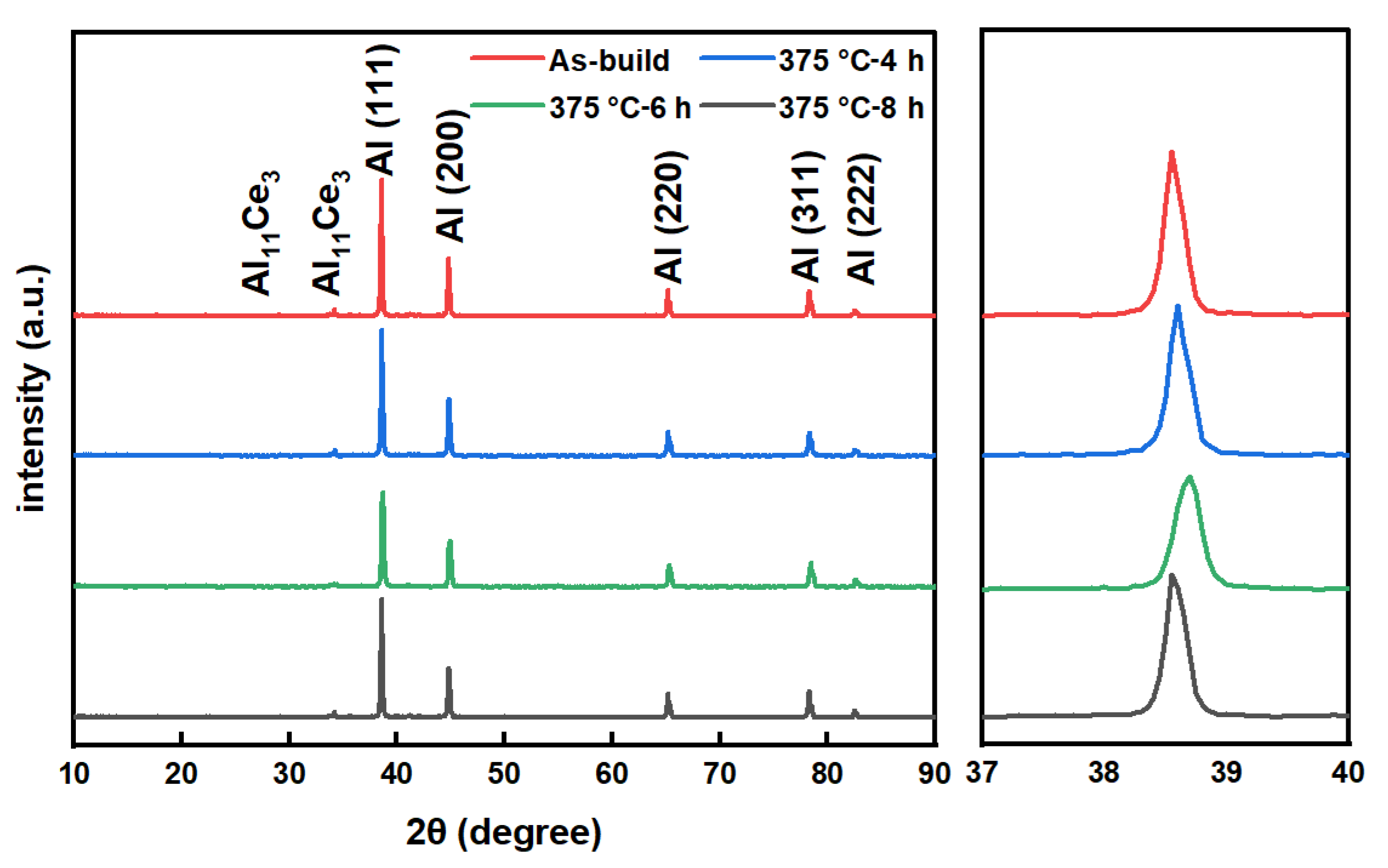
3.1. Microstructural Analysis
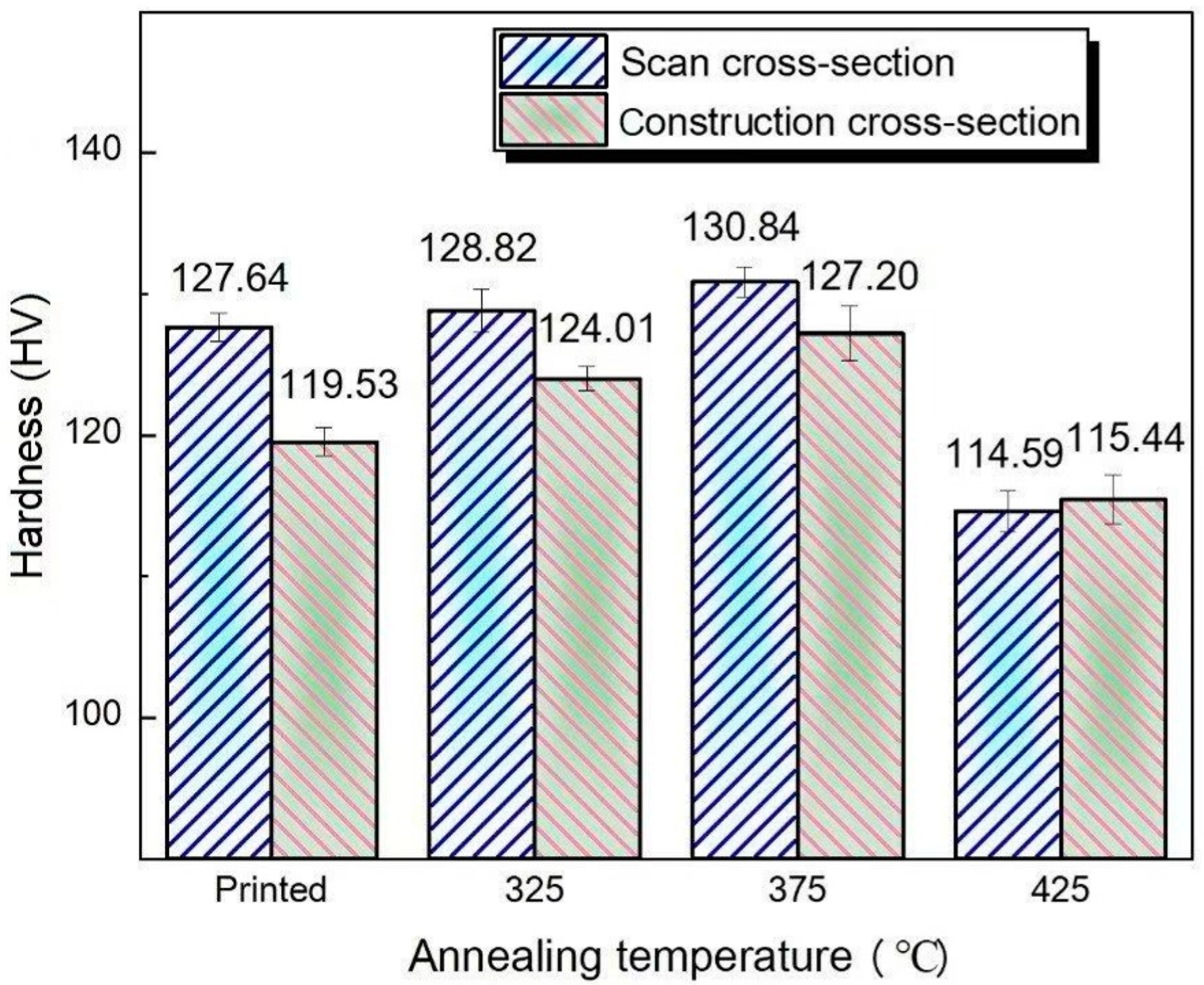
Figure 6 shows the microstructure of the Al-3.0Ce-0.9Ca-1.9Mn-1.2Zr alloy samples, both printed and annealed, formed by SLM after electrolytic polishing and anodic coating under a polarizing microscope. Figure 6a,c display a "fish scale" stacked distribution of the molten pool, a typical microstructure observed on the construction surface in laser additive manufacturing. In Figure 6b,d, parallel and staggered overlapping "cell-like" structures are visible, which are characterized by the scanning trajectory lines formed during the laser scanning process. Due to the Gaussian distribution of energy from the laser heat source, the aluminum melt pool experiences a large temperature gradient during solidification, leading to the formation of these scanning trajectory lines within the alloy. With the optimization of SLM process parameters, there are almost no crack defects or large-aperture lack-of-fusion defects on the construction and scanning surfaces, which exhibit columnar crystals inside the molten pool. Compared to the columnar crystals in the printed melt pool, the columnar crystals in the heat-treated sample are smaller in size. Figure 6f,g show high-magnification polarized micrographs of the scanning surfaces of the SLM-formed Al-3.0Ce-0.9Ca-1.9Mn-1.2Zr alloy in both the printed and annealed states. The grain morphology of the scanning surface differs from that of the building surface, with columnar crystals perpendicular to the horizontal melt pool being difficult to observe, instead showing typical equiaxed crystal morphology. Figure 6a illustrates the quality of overlap in the vertical direction of the melt pool during the SLM process. With the printing layer thickness set at 40 μm in the process parameters, a smaller printing layer thickness helps reduce the unevenness of the powder bed surface during sample formation. The distance between the bottoms of two melt pools in the vertical direction was measured to be 42 μm, which is consistent with the pre-set printing layer thickness. Figure 6b shows the overlap of the Al-3.0Ce-0.9Ca-1.9Mn-1.2Zr alloy formed by SLM in the horizontal melt pool. Due to the scanning spacing being set at 130 μm during SLM, the overlap quality of the horizontal melt pool is more complex, influenced by multiple process parameters such as scanning spacing, laser spot diameter, and scanning speed. The distance between the centers of the two adjacent melt pools in the horizontal direction was measured to be 128 μm, which is in line with the 130 μm set in the process parameters. Due to the insufficient polishing depth of the sample shown in Figure 6b, all the melt pools in the horizontal direction appear within the same interlayer, making it difficult to observe the growth direction relationship of the horizontal melt pools across different printing layers. Figure 6d clearly shows the directional relationship of the horizontal melt pools in adjacent layers. The angle between the horizontal melt pools of the two adjacent printing layers in Figure 6d was measured to be 72°, which is consistent with the interlayer scanning strategy, where the alloy is deflected by 67° layer by layer. This strategy of gradually deflecting a certain angle layer by layer significantly reduces the anisotropy of the material and improves its mechanical properties.
To further characterize the microstructure of the annealed Al-3.0Ce-0.9Ca-1.9Mn-1.2Zr alloy formed by SLM, SEM observations were conducted on the annealed state of the alloy. Figure 7 shows the SEM microstructure of the SLM-formed Al-3.0Ce-0.9Ca-1.9Mn-1.2Zr alloy after annealing at 375 °C for 8 h with a laser power of 380 W. Based on the lower magnification shown in Figure 7a, the distribution and boundaries of the softened melt pool in the annealed state are visible. Due to the significant remelting phenomenon during the laser scanning of the Al-3.0Ce-0.9Ca-1.9Mn-1.2Zr alloy formed by SLM, the internal structure of the melt pool undergoes further changes after annealing. As a result, the arrangement of the melt pool becomes irregular, and only a small portion retains a fan-shaped structure. Figure 7b shows the boundary of the molten pool of the alloy in the heat-treated state. It can be seen that the molten pool boundary of this Al-3.0Ce-0.9Ca-1.9Mn-1.2Zr alloy presents a very clear and smooth circular arc shape. This is due to the gradient distribution in the laser energy of the Gaussian laser beam, and the center of the laser spot has a very large energy, which can penetrate and melt deeper alloy entities. The center of the alloy melt pool mainly appears gray, with only a small amount of precipitates being distributed, as shown in dark gray. Figure 7c shows the columnar crystal region of the Al-3.0Ce-0.9Ca-1.9Mn-1.2Zr alloy. It can be seen that in the columnar crystal region, the microstructure mainly presents a branched morphology with black and gray staggered distribution. This is because the columnar crystal region is often located at the center of the laser spot and has a large temperature gradient. Therefore, the aluminum liquid in the melt pool is subjected to lateral compression, resulting in a significant directional growth of the columnar crystal region (perpendicular to the melt pool boundary). Figure 7d shows the equiaxed crystal region of the Al-3.0Ce-0.9Ca-1.9Mn-1.2Zr alloy, which is concentrated at the boundary of the melt pool and mainly presents granular and petal-shaped morphology. Due to the extremely thin scanning layer thickness parameter (40 μm) set in the SLM process, the influence of in situ heat treatment during the forming process is significant (i.e., the melting and solidification process of the powder layer will affect the solid alloy of the previous layer). At the same time, the annealing process will cause a large amount of Ce element dissolved in the α-Al matrix to precipitate, forming an Al11Ce3 strengthening phase. Therefore, the microstructure inside the alloy is very complex.
Figure 8 shows the EBSD analysis result of the Al-3.0Ce-0.9Ca-1.9Mn-1.2Zr alloy printed samples and annealed samples, which underwent heat treatment at 375 °C for 8 h at different cross-sections. Table 2 presents the average grain size of the alloy at various cross-sections. The results showed that there was no significant change in the grain size of the alloy before and after annealing. These results indicate that the grain size of the Al-3.0Ce-0.9Ca-1.9Mn-1.2Zr alloy formed by SLM was extremely fine, and the grain morphology, along with the distribution at different cross-sections, varied significantly. This variation is attributed to the unique characteristics of the SLM process, which differ from traditional casting and other manufacturing methods. As a typical additive manufacturing process, SLM forms the alloy structure layer by layer, with each layer consisting of a molten pool. The addition of Zr element leads to the formation of heterogeneous nucleation points in the region with a large temperature gradient (near the boundary of the melt pool), resulting in the formation of very small equiaxed grains in this area, thus exhibiting a bimodal grain morphology [33]. The grain sizes of the printed and annealed SLM-formed Al-3.0Ce-0.9Ca-1.9Mn-1.2Zr samples differ, and the grain sizes at the construction surface and scanning surface of the same sample also vary. The grain size at the construction surface of the printed sample is 4.25 μm, which is larger than that at the scanning surface (2.59 μm). After annealing at 375°C for 8 h, the grain size at the construction surface decreased to 3.37 μm, while the grain size at the scanning surface remained almost the same, at 3.34 μm. The construction surface of the printed sample consists of large-oriented columnar crystals and smaller equiaxed crystals, showing a distinct bimodal structure. Following annealing at 375 °C for 8 h, many of the columnar crystals transformed into smaller equiaxed crystals, reducing the overall size of the columnar crystals. Due to the high degree of undercooling at the bottom of the molten pool during the SLM process, very fine equiaxed grains are formed, which results in equiaxed grains of various sizes on the scanning surface of the Al-3.0Ce-0.9Ca-1.9Mn-1.2Zr alloy. After annealing, many of these small equiaxed crystals transformed into larger ones, leading to a larger grain size at the scanning surface of the annealed alloy sample compared to the printed state. The combined effects of equiaxed crystal growth at the molten pool's bottom and the transformation of columnar crystals at the center into equiaxed crystals caused the grain size on the construction surface to decrease and that on the scanning surface to increase after annealing at 375 °C for 8 h. The strong orientation of the columnar crystals leads to significant performance differences between the construction and scanning surfaces of the SLM-formed specimens. As the heat-treatment temperature increases, the columnar crystals gradually transform into equiaxed crystals, and the melt pool structure evolves toward a more uniform equiaxed crystal arrangement. This transformation greatly reduces the anisotropy of the alloy, enhancing the uniformity of the material's properties across both surfaces.
To investigate the phase distribution and changes in Al-3.0Ce-0.9Ca-1.9Mn-1.2Zr alloy samples prepared by SLM before and after heat treatment, XRD tests were performed. The XRD patterns of the Al-3.0Ce-0.9Ca-1.9Mn-1.2Zr alloy samples before and after heat treatment are shown in Figure 9. As seen in Figure 9, the Al peaks observed before and after heat treatment correspond to the (111), (200), (220), (311), and (222) planes, due to the low content of Ce element in the alloy, only 3.0 wt.%, Therefore, the diffraction peak of the Al11Ce3 phase in the Al-3.0Ce-0.9Ca-1.9Mn-1.2Zr alloy is not obvious. These results indicate that, with the extension of the 375 °C holding time, both the α-Al matrix and the Al11Ce3 crystal structure remained unchanged, and no new phases were detected. The XRD patterns of Al-3.0Ce-0.9Ca-1.9Mn-1.2Zr alloy samples formed by SLM after different holding times at 375°C are also presented in Figure 9. All samples, regardless of holding time, contain both the α-Al and Al11Ce3 phases. The diffraction peak of α-Al (111) in the sample initially shifts toward higher angles as the holding time increases. However, when the annealing time exceeds 6 h, this peak shifts back toward lower angles. This phenomenon is primarily attributed to the precipitation of the Al11Ce3 phase in the early stages of annealing. As the solid solution of Ce in the α-Al matrix precipitates, the crystal diffraction peak shifts to higher angles. With increasing holding time, the amount of solid solution Ce in the α-Al matrix decreases, and the precipitation kinetics of Al11Ce3 phase slows, and even some Al11Ce3 phase solid dissolves into the α-Al matrix, which causes the α-Al (111) diffraction peak to start moving toward lower angles.

3.2. Hardness

Due to the differences in metallurgical bonding time and the significant temperature gradient between the longitudinal and transverse sections formed during SLM, the alloys produced by SLM exhibit notable anisotropy. The boundary density of the molten pool on the construction surface is higher than that on the scanning surface, resulting in different hardness values between the construction and scanning surfaces of the formed alloy. Figure 10 presents the microhardness of the printed and annealed Al-3.0Ce-0.9Ca-1.9Mn-1.2Zr alloy samples formed by SLM at different cross-sections. Table 3 shows the average hardness and variation across different cross-sections of the alloy. The anisotropy of the alloy in its original printed state is quite pronounced. The microhardness of the scanning surface of the SLM-formed Al-3.0Ce-0.9Ca-1.9Mn-1.2Zr alloy in its original printed state is 128 HV, while the microhardness of the construction surface is only 120 HV, resulting in a difference of 8 HV. After annealing at 325 °C for 8 h, the microhardness of the scanning surface slightly increased to 129 HV, and the construction surface microhardness increased to 124 HV. The increase in microhardness on the construction surface was greater than that on the scanning surface. At this stage, the difference between the construction and scanning surfaces decreased to 4 HV, reducing the anisotropy of the alloy. With an 8 h holding time, when the annealing temperature was raised to 375 °C, the microhardness of both the construction and scanning surfaces continued to rise. The scanning surface microhardness increased slightly to 131 HV, while the construction surface microhardness increased to 127 HV. The difference in microhardness between the surfaces decreased further to 4 HV, indicating a further reduction in the anisotropy of the alloy. However, when the annealing temperature was increased to 425 °C with the holding time still at 8 h, the microhardness of both surfaces decreased instead of increasing. The microhardness of the scanning surface decreased significantly to 114 HV, and the construction surface microhardness decreased to 115 HV. In contrast to the results from other heat-treatment conditions, at this temperature, the microhardness of the construction surface was slightly higher than that of the scanning surface, and the anisotropy of the alloy disappeared. During the annealing process at 325 °C, 375 °C, and 425 °C, the grain size of the original printed state SLM-formed Al-3.0Ce-0.9Ca-1.9Mn-1.2Zr alloy became more refined. The large-sized columnar crystals gradually transformed into smaller equiaxed crystals. However, as the annealing temperature reached 425 °C, the coarsening of Al11Ce3 particles in the α-Al matrix resulted in a reduction in hardness. At this point, the strengthening effect of grain refinement was no longer sufficient to offset the negative impact of microstructure coarsening, leading to a decrease in microhardness.

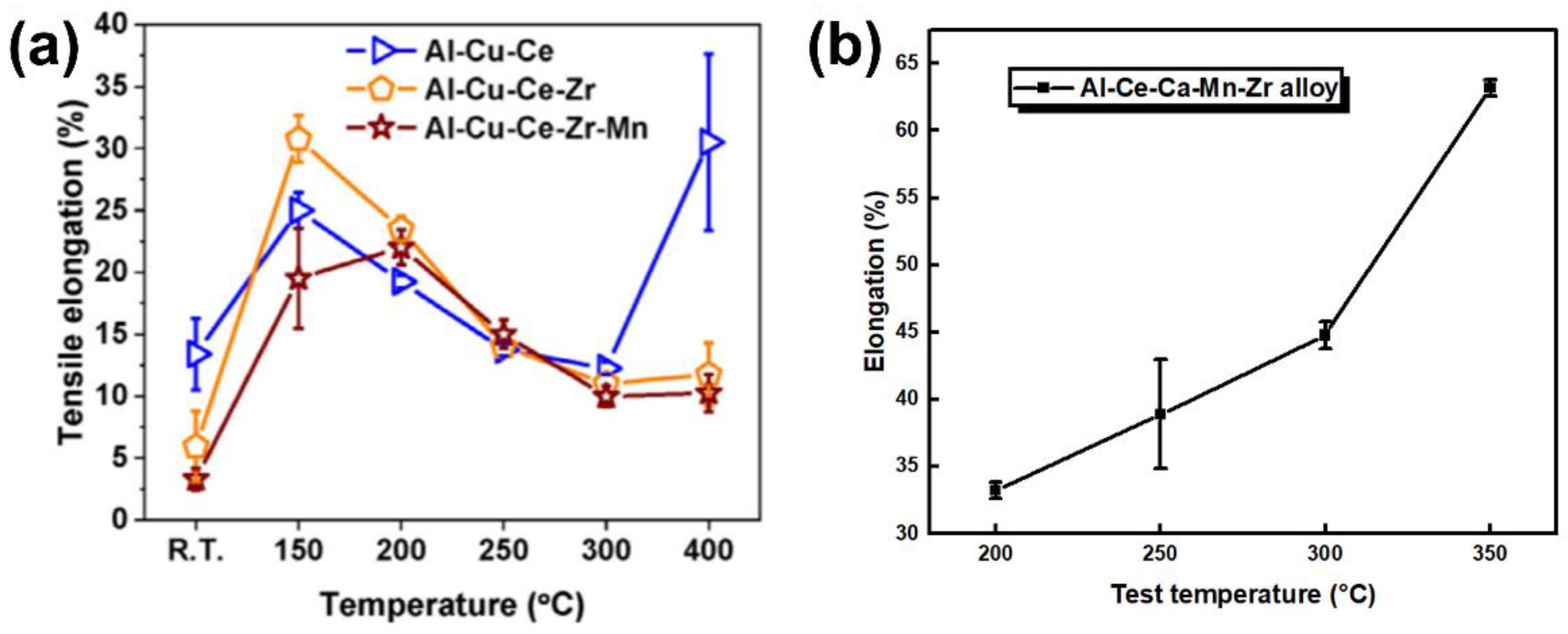
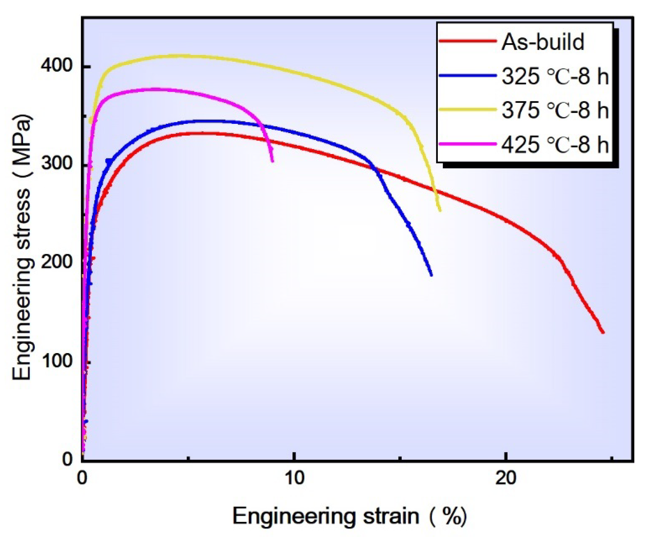
3.3. Tensile Property

Figure 11 shows the stress–strain curves of Al-3.0Ce-0.9Ca-1.9Mn-1.2Zr alloy formed by SLM at temperatures of 200 °C, 250 °C, 300 °C, and 350 °C, under a laser power of 380 W. Table 4 presents the tensile strength, yield strength, and elongation of the Al-3.0Ce-0.9Ca-1.9Mn-1.2Zr alloy at different testing temperatures. As the temperature increases, the mechanical properties of the alloy exhibit a decreasing trend. When the testing temperature is raised from 200 °C to 300 °C, the ultimate tensile strength and yield strength of the alloy decrease from 217 ± 0 MPa and 167 ± 17 MPa to 156 ± 9 MPa and 144 ± 8 MPa, respectively. This decrease is relatively small, and the yield strength remains above 140 MPa at 250 °C. However, when the temperature continues to increase to 300 °C, the ultimate tensile strength and yield strength further decrease to 91 ± 4 MPa and 84 ± 4 MPa, respectively. While this marks a significant decrease compared to 250 °C, the ultimate tensile strength still remains near 100 MPa. At 350°C, the ultimate tensile strength and yield strength drop to 61 ± 5 MPa and 57 ± 5 MPa, respectively. Notably, the difference between the yield strength and ultimate tensile strength of the alloy decreases as the temperature increases. At room temperature, the yield strength is 88 MPa lower than the ultimate tensile strength, but at 350 °C, this difference narrows to just 4 MPa. This behavior can be attributed to the softening of the α-Al matrix at high temperatures, causing the alloy's properties to be predominantly influenced by the harder Al11Ce3 phase. As the temperature increases, the softening of the α-Al matrix becomes more pronounced, which results in the yield strength becoming closer to the ultimate tensile strength.
Figure 12 shows the elongation at break of different SLM-formed Al alloys under high-temperature conditions. In Figure 12a, the Al-Cu-Ce, Al-Cu-Ce-Zr, and Al-Cu-Ce-Zr-Mn alloys exhibit a significant decrease in elongation between 150 °C and 300 °C, triggering the deformation failure mechanism of these alloys under high-temperature conditions. This results in the initiation of failure and a reduction in tensile elongation, with the lowest elongation observed at 300 °C. The decrease in elongation not only negatively impacts the shaping and processing performance of the material but is also indicative of reduced heat resistance. To address this issue, this study incorporated Ca into the Al-Ce alloy to mitigate the problem of shaping failure under high-temperature conditions. As shown in Figure 12b and Table 4, the elongation of Al-3.0Ce-0.9Ca-1.9Mn-1.2Zr alloy formed by SLM at testing temperatures of 200 °C, 250 °C, 300 °C, and 350 °C was 32.2 ± 0.6%, 39.9 ± 4.1%, 44.8 ± 1.0%, and 63.2 ± 0.6%, respectively. Over the temperature range of 200 °C to 350 °C, the elongation of Al-3.0Ce-0.9Ca-1.9Mn-1.2Zr alloy shows an upward trend, with a significant increase in elongation observed when the temperature rises from 300°C to 350°C. These results indicate that the modification of the Al-Ce alloy with Ca effectively alleviates the issue of shaping failure in high-temperature environments. The findings demonstrate that the SLM-formed Al-3.0Ce-0.9Ca-1.9Mn-1.2Zr alloy has excellent high-temperature yield strength and superior mechanical properties.
Figure 13 shows the engineering stress–strain curves of Al-3.0Ce-0.9Ca-1.9Mn-1.2Zr alloy printed and annealed samples formed by SLM, and Table 5 presents the mechanical properties of these samples. The results indicate that annealing treatment at different heat-treatment temperatures for 8 h leads to varying degrees of improvement in the tensile strength and yield strength of the SLM-formed Al-3.0Ce-0.9Ca-1.9Mn-1.2Zr alloy, while the elongation decreases. The most significant improvement in tensile strength and yield strength was observed at a heat-treatment temperature of 375 °C. The tensile strength, yield strength, and elongation of the printed sample are 333 MPa, 245 MPa, and 24.4%, respectively. After annealing at 325 °C for 8 h, the tensile strength and yield strength increased slightly by 16.4%, while the elongation decreased. When the heat-treatment temperature was increased to 375 °C, the tensile strength of the sample increased significantly to 411 MPa, the yield strength reached 359 MPa, and the elongation improved by 16.8%. These values were 21.5% and 31.6% higher than the original printed alloy, respectively, though the elongation decreased by 45.1%. When the heat-treatment temperature was further increased to 425 °C, the room temperature tensile properties of the alloy decreased. The tensile strength and yield strength dropped to 377 MPa and 349 MPa, respectively, while the elongation significantly decreased to 9.0%. This behavior is attributed to the rapid melting and solidification characteristics of the SLM process, which leads to a large amount of Ce element dissolving in the α-Al matrix, forming a supersaturated solid solution. During the annealing process, Ce precipitates from the α-Al matrix and generates the Al11Ce3 strengthening phase, which improves the tensile strength and yield strength. However, the annealing process reduces the shaping ability of the Al-3.0Ce-0.9Ca-1.9Mn-1.2Zr alloy, as evidenced by the decrease in elongation. Under the 375 °C/8 h annealing process, the tensile strength of the formed sample increased significantly by 78 MPa, while the yield strength also improved. This increase is due to the fact that, after annealing, the sample not only releases the stress generated during the SLM process but also facilitates the dispersion and precipitation of alloying elements. This precipitation strengthening effect enhances the mechanical properties of the alloy.
The fracture morphology of SLM-formed Al-3.0Ce-0.9Ca-1.9Mn-1.2Zr tensile specimens in their original printed state and in different annealed and heat-treated states is shown in Figure 14. A large number of ductile dimples are present in the room temperature tensile fracture morphology of the heat-treated samples with different annealing temperatures after an 8 h holding time, which are generally consistent with the original printed room temperature tensile fracture morphology, showing typical ductile fracture. However, compared to the original printed state of the alloy, the size and depth of the ductile dimples in the room temperature tensile fracture morphology of the annealed alloy are significantly reduced. In the high-magnification image showing the fracture morphology of the annealed sample at 325 °C for 8 h, a small number of columnar crystals can be observed. This is due to the formation of more second-phase particles during the annealing process, along with the precipitation and coarsening of precipitated phases at the grain boundaries, which weakens the intergranular bonding force and makes it easier for intergranular fractures to occur near the grain boundaries. This is also reflected in the alloy's elongation. At the same time, a small number of porosity defects can still be observed in the high-magnification image, as shown in Figure 14a,c,d. These pore defects can, to some extent, reduce the favorable mechanical properties of the alloy.

4. Conclusions

This article describes a new type of lightweight heat-resistant aluminum alloy material and explores the effects of process parameters and heat-treatment processes on its microstructure and properties. The main conclusions are as follows:
(1) The microstructure shows that the printed alloy has a heterogeneous grain structure, with very small equiaxed grains formed at the heat-affected zone of the melt pool boundary. Under EBSD observation, both the printed and annealed melt pools exhibit a bimodal microstructure of columnar and equiaxed crystals.
(2) The SLM-formed Al-3.0Ce-0.9Ca-1.9Mn-1.2Zr alloy exhibits significant anisotropy, manifested as differences in microhardness between the construction surface and scanning surface of the specimen. After annealing treatment at 325 ℃/8 h, 375 ℃/8 h, and 425 ℃/8 h, the hardness difference between the scanned and construction surfaces of the original printed sample gradually decreased from 8 HV to 5 HV and −1 HV, and the anisotropy gradually decreased until it disappeared.
(3) The tensile strength, yield strength, and elongation of SLM-formed Al-3.0Ce-0.9Ca-1.9Mn-1.2Zr alloy were 333 MPa, 245 MPa, and 24.4%, respectively. When the holding time was 8 h, the mechanical properties of the alloy first increase and then decrease as the annealing temperature increases. The sample annealed at 375 ℃ has the best tensile properties. Under this heat-treatment process, the tensile strength, yield strength, and elongation of the alloy reached 411 MPa, 267 MPa, and 16.4%. The new alloy exhibits excellent lightweight and heat-resistant comprehensive performance, and has good application prospects in the automotive industry, alloy coatings, ships, and other fields.

Author Contributions

Conceptualization, M.W.; writing—original draft preparation, W.Z. and Y.S.; writing—review and editing, D.C., J.L., B.S., X.Y. and Z.Z.; supervision, D.C., J.L. and B.S. All authors have read and agreed to the published version of the manuscript.

Funding

This research has been funded by the Major Research Development Program of Wuhu (Grant No. 2023yf107) and Start-up funding of Anhui Polytechnic University (Grant No. 2022YQQ006).

Institutional Review Board Statement

Not applicable.

Informed Consent Statement

Not applicable.

Data Availability Statement

Data are contained within the article.

Conflicts of Interest

Author Xiaodan Yu was employed by the company Wuhu Yongda Tech. Co. Ltd. Author Dongting Cai was employed by the company Anhui Shengerwo Intelligent Equipment Co. Ltd. Author Baoxiang Shen was employed by the company Cnpc Powder China Ltd. The remaining authors declare that the research was conducted in the absence of any commercial or financial relationships that could be construed as a potential conflict of interest.

References

  1. Buchanan, C.; Gardenr, L. Metal 3D printing in construction: A review methods, research, applications, opportunities and challenges. Eng. Struct. 2019, 180, 332–348. [Google Scholar] [CrossRef]
  2. Dalmau, A.; Richard, C.; Igual–Munoz, A. Degradation mechanisms in martensitic stainless steels: Wear, corrosion and tribocorrosion appraisal. Tribol. Int. 2018, 121, 167. [Google Scholar] [CrossRef]
  3. Wu, Y.; Wang, Z.; Chen, J.; Ma, Y.; Yan, Y.; Qiao, L. Effect of frictional frequency on the subsurface evolution of 316 L stainless steel in tribocorrosion and its influence on the synergistic effect between corrosion and wear. Tribol. Int. 2023, 178, 108026. [Google Scholar] [CrossRef]
  4. Cajner, F.; Kovacic, S.; Rafael, H.; Vugrinčić, A.; Šimunović, V.; Gržeta, B. Influence of nitriding on corrosion resistance of martensitic X17CrNi16-2 stainless steel. Mater. Werkst. 2015, 46, 69. [Google Scholar] [CrossRef]
  5. Guo, S.; Li, Y.; Gu, J.; Liu, J.; Peng, Y.; Wang, P.; Zhou, Q.; Wang, K. Microstructure and mechanical properties of Ti6Al4V/B4C titanium matrix composite fabricated by selective laser melting (SLM). J. Mater. Res. Technol. 2023, 23, 1934–1946. [Google Scholar] [CrossRef]
  6. Cain, V.; Thijs, L.; Van Humbeeck, J.; Van Hooreweder, B.; Knutsen, R. Crack propagation and fracture toughness of Ti6Al4V alloy produced by selective laser melting. Addit. Manuf. 2015, 5, 68–76. [Google Scholar] [CrossRef]
  7. Nguyen, H.D.; Pramanik, A.; Basak, A.K.; Dong, Y.; Prakash, C.; Debnath, S.; Shankar, S.; Jawahir, I.S.; Dixit, S.; Buddhi, D. A critical review on additive manufacturing of Ti-6Al-4V alloy: Microstructure and mechanical properties. J. Mater. Res. Technol. 2022, 18, 4641–4661. [Google Scholar] [CrossRef]
  8. Li, G.; Brodu, E.; Soete, J.; Wei, H.; Liu, T.; Yang, T.; Liao, W.; Vanmeensel, K. Exploiting the rapid solidification potential of laer powder bed fusion in high strength and crack-free Al-Cu-Mg-Mn-Zr alloys. Addit. Manuf. 2021, 47, 102210. [Google Scholar]
  9. Mehta, A.; Zhou, L.; Huynh, T.; Park, S.; Hyer, H.; Song, S.; Bai, Y.; Imholte, D.D.; Woolstenhulme, N.E.; Wachs, D.M.; et al. Additive manufacturing and mechanical properties of the dense and crack free Zr-modified aluminum alloy 6061 fabricated by the laser-powder bed fusion. Addit. Manuf. 2021, 41, 101966. [Google Scholar] [CrossRef]
  10. Martin, J.H.; Yahata, B.D.; Hundley, J.M.; Mayer, J.A.; Schaedler, T.A.; Pollock, T.M. 3D printing of high-strength aluminium alloys. Nature 2017, 549, 365–3296. [Google Scholar] [CrossRef]
  11. Yang, K.V.; Rometsch, P.; Jarvis, T.; Rao, J.; Cao, S.; Davies, C.; Wu, X. Porosity formation mechanisms and fatigue response in Al-Si-Mg alloys made by selective laser melting. Mater. Sci. Eng. A 2018, 712, 166–174. [Google Scholar] [CrossRef]
  12. Hyer, H.; Zhou, L.; Park, S.; Gottsfritz, G.; Benson, G.; Tolentino, B.; McWilliams, B.; Cho, K.; Sohn, Y. Understanding the laser powder bed fusion of AlSi10Mg alloy. Metallogr. Microstruct. Anal. 2020, 9, 484–502. [Google Scholar] [CrossRef]
  13. Ishfaq, K.; Abdullah, M.; Mahmood, M.A. A state-of-the-art direct metal laser sintering of Ti6Al4V and AlSi10Mg alloys: Surface roughness, tensile strength, fatigue strength and microstructure. Opt. Laser Technol. 2021, 143, 107366. [Google Scholar] [CrossRef]
  14. Wu, J.; Wang, X.Q.; Wang, W.; Attallah, M.M.; Loretto, M.H. Microstructure and strength of selective laser melted AlSi10Mg. Acta Mater. 2016, 117, 311–320. [Google Scholar] [CrossRef]
  15. Fousova, M.; Dvorsky, D.; Michalcoval, A.; Vojtěch, D. Changes in the microstructure and mechanical properties of additively manufactured AlSi10Mg alloy after exposure to elevated temperatures. Mater. Charact. 2018, 137, 119–126. [Google Scholar] [CrossRef]
  16. Weiss, D. Improved high-temperature aluminum alloys containing cerium. J. Mater. Eng. Perform. 2019, 28, 1903–1908. [Google Scholar] [CrossRef]
  17. Weiss, D.; Rios, O.; Sims, Z.; McCall, S.; Ott, R. Casting Characteristics of High Cerium Content Aluminum Alloys. In Light Metals; Springer International Publishing: San Diego, CA, USA, 2017. [Google Scholar]
  18. Czrwinski, F. Thermal stability of aluminum-cerium binary alloys containing the Al-Al11Ce3 eutectic. Mater. Sci. Eng. A 2021, 809, 140973. [Google Scholar] [CrossRef]
  19. Tradowsky, U.; White, J.; Ward, R.M.; Read, N.; Reimers, W.; Attallah, M.M. Selective laser melting of AlSi10Mg: Influence of post-processing on the microstructural and tensile properties development. Mater. Des. 2016, 105, 212–222. [Google Scholar] [CrossRef]
  20. Nie, X.; Zhang, H.; Zhu, H.; Hu, Z.; Ke, L.; Zeng, X. Analysis of processing parameters and characteristics of selective laser melted high strength Al-Cu-Mg alloys: From single tracks to cubic samples. J. Mater. Process. Technol. 2018, 256, 69–77. [Google Scholar] [CrossRef]
  21. Yang, K.V.; Rometsch, P.; Davies, C.H.; Huang, A.; Wu, X. Effect of heat treatment on the microstructure and anisotropy in mechanical properties of A357 alloy produced by selective laser melting. Mater. Des. 2018, 154, 275–290. [Google Scholar] [CrossRef]
  22. Takata, N.; Kodaira, H.; Sekizawa, K.; Suzuki, A.; Kobashi, M. Change in microstructure of selectively laser melted AlSi10Mg alloy with heat treatments. Mater. Sci. Eng. A 2017, 704, 218–228. [Google Scholar] [CrossRef]
  23. Plotkowski, A.; Rios, O.; Sridharan, N.; Sims, Z.; Unocic, K.; Ott, R.; Dehoff, R.; Babu, S. Evaluation of an Al-Ce alloy for laser additive manufacturing. Acta Mater. 2017, 126, 507–519. [Google Scholar] [CrossRef]
  24. Sims, Z.C.; Rios, O.R.; Weiss, D.; Turchi, P.E.; Perron, A.; Lee, J.R.; Li, T.T.; Hammons, J.A.; Bagge-Hansen, M.; Willey, T.M. High performance aluminum-cerium alloys for high temperature applications. Mater. Horiz. 2017, 4, 1070–1078. [Google Scholar] [CrossRef]
  25. Liu, Y.; Michi, R.A.; Dunand, D.C. Cast near-eutectic Al-12.5%Ce alloy with high coarsening and creep resistance. Mater. Sci. Eng. A 2019, 767, 138440. [Google Scholar] [CrossRef]
  26. Su, Z.; Zeng, Z.; Zhang, S.; Meng, X.; Xu, S. Trace Ca alloying enhance simultaneously strength and ductility of squeeze-cast Al-5Cu-0.5Mn-Based Alloys. J. Mater. Sci. Technol. 2024, 191, 89–105. [Google Scholar] [CrossRef]
  27. Akopyan, T.; Sviridova, T.; Belov, N.; Letyagin, N.; Korotitskiy, A. Intermetallic compounds in equilibrium with aluminum in Al–Ca–Cu ternary alloying system. Trans. Nonferrous Met. Soc. China 2024, 34, 1380–1392. [Google Scholar] [CrossRef]
  28. Belov, N.; Akopyan, T.; Tsydenov, K.; Sviridova, T.; Cherkasov, S.; Kovalev, A. Effect of Ca addition on structure, phase composition and hardness of Al–6% Cu–2% Mn sheet alloy. J. Alloys Compd. 2024, 1009, 176955. [Google Scholar] [CrossRef]
  29. Akopyan, T.K.; Belov, N.A.; Letyagin, N.V.; Sviridova, T.A.; Cherkasov, S.O. New quaternary eutectic Al-Cu-Ca-Si system for designing precipitation hardening alloys. J. Alloys Compd. 2024, 993, 174695. [Google Scholar] [CrossRef]
  30. Du, H.; Zhang, S.; Zhang, B.; Tao, X.; Yao, Z.; Belov, N.; van der Zwaag, S.; Liu, Z. Ca-modified Al–Mg–Sc alloy with high strength at elevated temperatures due to a hierarchical microstructure. J. Mater. Sci. 2021, 56, 16145–16157. [Google Scholar] [CrossRef]
  31. Shurkin, P.; Letyagin, N.; Yakushkova, A.; Samoshina, M.; Ozherelkov, D.Y.; Akopyan, T. Remarkable thermal stability of the Al-Ca-Ni-Mn alloy manufactured by laser-powder bed fusion. Mater. Lett. 2021, 285, 129074. [Google Scholar] [CrossRef]
  32. Biffi, C.A.; Fiocchi, J.; Tuissi, A. Selective laser melting of AlSi10Mg: Influence of process parameters on Mg2Si precipitation and Si spheroidization. J. Alloys Compd. 2018, 755, 100–107. [Google Scholar] [CrossRef]
  33. Ren, Y.; Dong, P.; Zeng, Y.; Yang, T.; Huang, H.; Chen, J. Effect of heat treatment on properties of Al-Mg-Sc-Zr alloy printed by selective laser melting. Appl. Surf. Sci. 2022, 574, 151471. [Google Scholar] [CrossRef]
  34. Bahl, S.; Plotkowski, A.; Sisco, K.; Leonard, D.N.; Allard, L.F.; Michi, R.A.; Poplawsky, J.D.; Dehoff, R.; Shyam, A. Elevated temperature ductility dip in an additively manufactured Al-Cu-Ce alloy. Acta Mater. 2021, 220, 117285. [Google Scholar] [CrossRef]
Figure 1. Particle size distribution of Al-3.0Ce-0.9Ca-1.9Mn-1.2Zr alloy powder.
Coatings 15 00247 g001
Figure 2. Morphology of the Al-3.0Ce-0.9Ca-1.9Mn-1.2Zr alloy powder.
Coatings 15 00247 g002
Figure 3. XRD pattern of the Al-3.0Ce-0.9Ca-1.9Mn-1.2Zr alloy powder.
Coatings 15 00247 g003
Figure 4. Laser scanning strategy for SLM-formed alloys.
Coatings 15 00247 g004
Figure 5. Dimensions of tensile test specimens: (a) room temperature tensile test specimen; (b) high temperature tensile test specimen.
Coatings 15 00247 g005
Figure 6. Electrolytic polishing of the anode coating: (a,e) XZ-plane of the as-build state; (b,f) XY-plane of the as-build state; (c,g) XZ-plane of the 375 ℃/8 h annealed state; (d,h) XY-plane of the 375 ℃/8 h annealed state.
Coatings 15 00247 g006
Figure 7. Boundary diagram of the annealed molten pool in the SLM-formed Al-3.0Ce-0.9Ca-1.9Mn-1.2Zr alloy: (a) multipass molten pool morphology; (b) boundary of molten pool; (c) columnar crystal region; (d) equiaxed crystal region.
Coatings 15 00247 g007
Figure 8. EBSD analysis of formed alloy: (a) XY-plane of the as-build state with its grain size distribution statistics (a1); (b) XY-plane of the as-build state with its grain size distribution statistics (b1); (c) XY-plane of 375 ℃/8 h annealed state with its grain size distribution statistics (c1); (d) XZ-plane of 375 ℃/8 h annealed state with its grain size distribution statistics (d1).
Coatings 15 00247 g008
Figure 9. XRD of SLM-formed Al-3.0Ce-0.9Ca-1.9Mn-1.2Zr alloy in its original printed and annealed states.
Coatings 15 00247 g009
Figure 10. Microhardness of SLM-formed Al-3.0Ce-0.9Ca-1.9Mn-1.2Zr alloy scan and construction cross-sections for the printed state and at different annealing temperatures.
Coatings 15 00247 g010
Figure 11. Engineering stress–strain curves of SLM-formed Al-3.0Ce-0.9Ca-1.9Mn-1.2Zr alloy at different testing temperatures.
Coatings 15 00247 g011
Figure 12. Tensile elongation of alloys at different testing temperature: (a) Tensile elongation of the three alloys Al-Ce-Ce, Al-Cu-Ce-Zr, and Al-Cu-Ce-Zr-Mn plotted together with all of them showing the dip in elevated temperature ductility (adapted from reference [34], © Elsevier). (b) SLM-formed Al-3.0Ce-0.9Ca-1.9Mn-1.2Zr alloy.
Coatings 15 00247 g012
Figure 13. Engineering stress–strain of SLM-formed Al-3.0Ce-0.9Ca-1.9Mn-1.2Zr alloy printed and heat-treated specimens.
Coatings 15 00247 g013
Figure 14. Fracture morphology under different heat-treatment parameters: (a,e) original printed state; (b,f) 325 °C/8 h; (c,g) 375 °C/8 h; (d,h) 425 °C/8 h.
Coatings 15 00247 g014
Table 1. Composition of the Al-3.0Ce-0.9Ca-1.9Mn-1.2Zr alloy elements (wt.%).
AlCeCaMnZrFe
Bal.3.00.91.91.2<0.05
Table 2. Average grain size of Al-3.0Ce-0.9Ca-1.9Mn-1.2Zr alloy formed by SLM in printed and heat-treated states at different cross-sections.
Construction Surface/μmScanning Surface/μm
As-build state4.252.59
Annealed state3.373.34
Table 3. Microhardness of SLM-formed Al-3.0Ce-0.9Ca-1.9Mn-1.2Zr alloy for printed and annealed states at different temperatures.
Temperature/°CPrinting State325375425
Construction surface/HV120124127115
Scanning surface/HV128129131114
Average/HV124126129115
Difference/HV854−1
Table 4. High-temperature tensile properties of SLM-formed Al-3.0Ce-0.9Ca-1.9Mn-1.2Zr alloy at different test temperatures.
Temperature/°CUTS/MPaYS/MPaEl/%
200217 ± 0167 ± 1733.2 ± 0.6
250156 ± 9144 ± 839.9 ± 4.1
30091 ± 4.84 ± 444.8 ± 1.0
35061 ± 557 ± 563.2 ± 0.6
Table 5. Mechanical properties of Al-3.0Ce-0.9Ca-1.9Mn-1.2Zr alloy in the printed and annealed state.
Annealing Temperature/°CHolding Time/
h
Tensile Strength/MPaYield Strength/MPaElongation/
%
200 33324524.4
3258 34526716.4
3758 41135916.8
4258 3773499.0
Disclaimer/Publisher’s Note: The statements, opinions and data contained in all publications are solely those of the individual author(s) and contributor(s) and not of MDPI and/or the editor(s). MDPI and/or the editor(s) disclaim responsibility for any injury to people or property resulting from any ideas, methods, instructions or products referred to in the content.

