Article

Residual Stress Model in Laser Direct Deposition Based on Energy Equation

1
School of Intelligent Manufacturing and Mechanical Engineering, Hunan Institute of Technology, Hengyang 421002, China
2
School of Mechanical and Electrical Engineering, Hunan University of Science and Technology, Xiangtan 411201, China
3
Huizhou Yiwei Lithium Energy Co., Ltd., Huizhou 516000, China
*
Author to whom correspondence should be addressed.
Coatings 2025, 15(2), 217; https://doi.org/10.3390/coatings15020217
Submission received: 19 January 2025 / Revised: 31 January 2025 / Accepted: 10 February 2025 / Published: 12 February 2025

Abstract

:
In this paper, 316 L stainless steel deposited samples were fabricated by direct layer deposition (DED) using both continuous-wave (CW) and pulsed-wave (PW) laser modes. Effects of laser modes on residual stress of deposited samples were investigated. On this basis, a mathematical model of thermal stress evolution during DED was established for the first time based on the energy equation. The variation law of thermal stress on the top of the substrate under multi-material and multi-process conditions was qualitatively predicted and the corresponding residual stress reduction mechanism has been studied using this model. Meanwhile, in situ thermal strain evolution is used to prove the correctness of the mathematical model. This model lays the foundation for predicting the thermal stress evolution and the magnitude of the residual stress of deposited samples under multi-material and process conditions during DED.

1. Introduction

Direct laser deposition is a laser additive manufacturing technology that offers great advantages and opportunities compared to traditional material removal technology. However, during the layer-by-layer deposition process, the “spot” laser heat source causes a steep temperature gradient [1,2,3] in the deposited sample, which results in a dramatic expansion and contraction of the metal material in a very short period of time. Thermal stress arising in the deposited sample is caused by temperature gradient. The thermal mechanism between the heat source and the material is extremely complex, and the thermophysical process is difficult to control and has many influencing factors, resulting in large residual stresses within the deposited. Residual stress, which develops from plastic thermal stress when the material is cooled, is harmful to the components, such as reducing the strength and fatigue limit of the workpiece, causing brittle fracture, accelerating the corrosion rate of components in a corrosive atmosphere, etc. Therefore, characterizing the thermal stress of the deposited accurately is of great significance to study how to control residual stress in the workpiece. Many methods have been performed to control the thermal stress and reduce the residual stress of deposited samples [4,5]. These methods are mainly adopted by reducing the temperature gradient, the release of thermal stress during deposition [6,7,8,9], and by post-processing the sample after deposition [10,11,12].
Zhao et al. [13] studied the influence of deposition path strategy on residual stress. They found that the out–in deposition sequence prominently contributes to lower residual stress due to faster heat dissipation and homogeneous temperature distribution during the cooling stage of the deposition process. Chen et al. [14] effectively reduced thermal and residual stress by manipulating heat accumulation using a preheating temperature of 300 °C and a larger layer thickness. Mathews et al. [15] considered a transverse deposition sequence to aggravate residual stress in the part, potentially increasing the risk of part failure, and the corresponding longitudinal deposition reduces the stress accumulation. Ghanavati et al. [16] found that longitudinal residual stress in each layer is partially relieved by the deposition of the subsequent layer due to the experience of reheating and cooling cycles. Klein et al. [17] proposed the introduction of inter-layer laser shock peening (LSP) in the laser deposition process can effectively improve the thermal stress state, so that the harmful tensile stresses are converted to compressive stresses, thus causing a reduction in residual stresses.
In recent years, Zou [18] and Zhou [19] found that the thermal stress of the deposited sample can be greatly reduced by in situ releasing the thermal stress during DED. These studies are useful indicators of the release of thermal stress and the elimination of residual stress. However, it is limited to studies on a single material and a single process condition, and the study of residual stress in laser additive manufacturing deposited is based on statistical laws and macroscopic effects obtained from a large number of experiments, and residual stress control methods can only be determined by experience. It is time-consuming and laborious to achieve stress optimization for DED multi-material and multi-process conditions. Consequently, it is necessary to establish a simple and effective mathematical model to realize the prediction of thermal stress evolution during DED under multi-material and multi-process conditions.
In this paper, residual stress with CW and PW mode during DED was first measured. Then, a mathematical model of thermal stress evolution of single-layer deposition with these two modes was established. The variation law of thermal stress on the top of the substrate under multi-material and multi-process conditions was qualitatively predicted and the corresponding residual stress reduction mechanism has been studied using this model. Meanwhile, in situ thermal strain evolution is used to prove the correctness of the mathematical model. This model lays the foundation for predicting the thermal stress evolution and the magnitude of the residual stress of deposited samples under multi-material and process conditions during DED.

2. Materials and Methods

Commercially available 316 L stainless steel powders were used. Single-track 10-layer deposition sample deposited on 316L stainless steel substrate. This experiment was fabricated by a YLS-5000-CL laser direct deposition system with a 1070 nm wavelength fiber laser. The processing parameters are listed in Table 1. According to the formula Q = P × t , Q represents heat energy input, P represents laser power, and t represents laser exit time. Q is kept consistent in both CW (S1) and PW (S2) modes. Consequently, the duty cycle and frequency were set to 75% and 10 Hz, respectively, for PW mode (S2). Other process parameters are as follows: the beam diameter is 1.2 mm, the powder feeding rate is 11.5 g/min, and the shielding gas is pure argon with 10 L/min.
The residual stress of deposited samples was measured by the contour method. It firstly uses a Coordinate Measuring Machine (CMM) to measure the deformation of the deposited samples caused by residual stress release. Then, the measured deformation results are integrated, smoothed, and processed into the finite element software ANSYS 15 version as input for the reverse calculation of residual stress. It is an acceptable technique to map the residual stress, a cross-sectional (2-D) map of the residual stresses normal to the cross-section can be provided [20]. An industrial camera with digital image correlation method (DIC) [21,22] was used to monitor in situ thermal strain with 0.1% precision, the image resolution is 640 × 480, and the image acquisition frequency was set to 0.05 Hz.

3. Results and Discussion

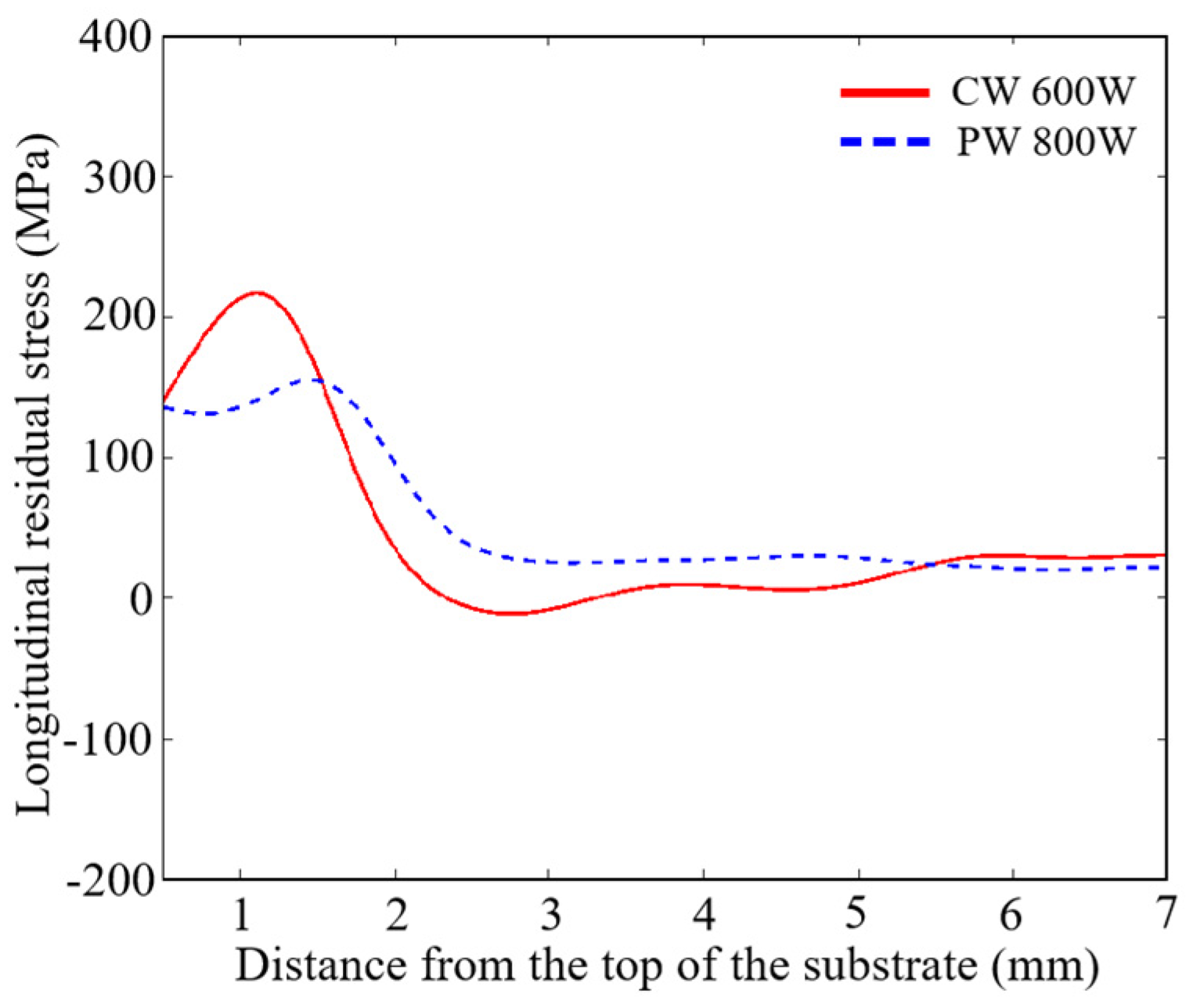
3.1. Residual Stresses

Figure 1 shows the longitudinal residual stresses of the deposited samples in the form of contour maps in both CW and PW modes. The longitudinal residual stresses are distributed horizontally in an approximate parabolic pattern near the top of the substrate. Tension stresses were observed at the middle and compression stresses at the ends. Along the depth direction, the longitudinal residual stress value undergoes a sharp change at the junction of the substrate and deposited, reaching the maximum tensile stress in this area. When approaching the bottom of the substrate, the residual stress gradually becomes compressive. This is due to the fact that the top of the substrate is heated by the presence of a heat source during DED; when the deposition is finished and the top of the substrate is gradually cooled down, the surface of the metal have a tendency to shrink; tensile stresses are generated due to the constraints of the underlying metal. Correspondingly, the bottom of the substrate has a tendency to expand, resulting in compressive stress. It is in accordance with the theory of self-equilibrium of tensile–compressive stresses on a free surface. It should be noted that in the yellow to red areas of the cloud map, there exists a small amount of excessive stress at the edges of the deposited samples, which is due to the systematic error caused by the inevitable sliding of the CMM probe when measuring the metal edges.
Although the stress distributions are not identical, the value of the maximum longitudinal residual stress is different. Figure 2 demonstrates the longitudinal residual stress data on the mid-line of the cross-section along the vertical direction from the maps in Figure 1. For the same thermal energy input, the maximum longitudinal residual stress in PW mode is 27.3% less than that in CW mode (213.6 MPa for CW mode and 155.2 MPa for PW mode, respectively). It is worth noting that the maximum longitudinal residual stress for the CW 600 W specimen is slightly higher than the yield strength of 316 L stainless steel (170 MPa). This is attributed to the strain-hardening effect of the material and triaxial stress state of stress [20,23]. In addition, the yield strength of 316 L stainless steel was reduced by high-temperature conditions, the material changed from brittle to ductile, and alloy elements with lower boiling temperatures were vaporized and evaporated because of the unstable melting process [24]. It affects the material composition, which in turn affects the mechanical and chemical properties of the produced components.

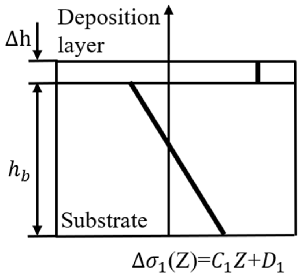
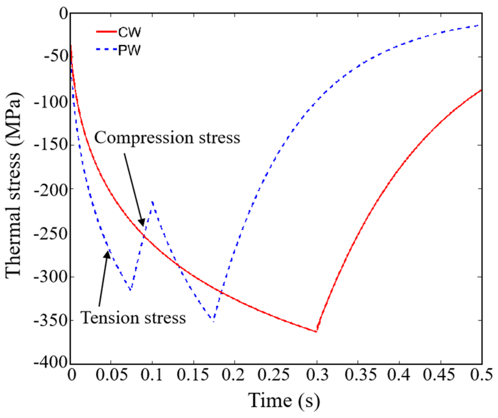
3.2. Mathematical Thermal Strain/Stress Model Under CW and PW Laser Modes

Methodology

The laser heat source for DED is generally a moving Gaussian heat source, as shown in Figure 3. The intensity distribution u 2 at any point on its spot can be expressed as follows:
u 2 = 2 π σ 2 exp 2 r 2 σ 2
where σ is the radius of the laser spot, and r is the variable, indicating the radius anywhere from the center of the laser spot.
Considering laser absorptivity η and laser peak power P , Gaussian spot laser power density P d r can be expressed as follows:
P d r = 2 η P π σ 2 exp 2 r 2 σ 2
Transform the coordinate system and take a micro element area Δ x ,   Δ y at r = 0   x 0 = 0 , y 0 = 0 . Assume that the laser moves along the x direction at the scanning speed U , as shown in Figure 4. Then, after time t, the laser power density at any point can be expressed as:
P d x , 0 = 2 η P π σ 2 exp 2 x 2 σ 2 = 2 η P π σ 2 exp 2 Ut 2 σ 2
For microelements Δ x , Δ y , Δ z at y = 0 , the increase in the maximum enthalpy per unit mass is as follows:
Δ H max Δ V = Δ x Δ y Δ z ρ Δ H max
where Δ z is the penetration depth of the molten pool, which can be expressed as follows [25]:
Δ z α × 2 σ U
where α Represents the thermal diffusion coefficient. Under the action of laser, the energy absorbed by micro elements is as follows [25]:
E absorb = 2 η P π σ 2 exp 2 Ut 2 σ 2 Δ x Δ y dt
Under the action of laser, the energy lost by micro elements is as follows [25]:
E diffusion = S α ρ Δ H max dt
where S represents the shape factor [26], ρ represents the density of the material. According to the energy conservation equation,
Δ H max Δ V = E absorb E diffusion
From Formulas (4), (6)–(8), the following formula can be obtained as follows:
Δ x Δ y Δ z ρ Δ H max = 2 η P π σ 2 exp 2 Ut 2 σ 2 Δ x Δ y dt S α ρ Δ H max dt
Mathematical model of thermal strain
Based on the energy equation in Section Methodology in Section 3.2, the thermal strain model of CW and PW during DED is derived:
For CW laser mode, the laser opening time is t , and the upper and lower integral of Formula (9) can be changed:
Δ x Δ y Δ z ρ Δ H max = 0 t 2 η P π σ 2 exp 2 Ut 2 σ 2 Δ x Δ y dt 0 t S α ρ Δ H max dt
By solving Formula (10), the following can be obtained:
Δ H max = M 1 1 exp S U α Δ x Δ y 2 σ t
where M 1 = Δ x Δ y η P π σ 2 S α ρ , according to [27], Δ x = Δ y = 2 σ , S = 4 σ . Then, Formula (11) can be changed to the following:
Δ H max = η P π σ α ρ × 1 exp U α 2 σ 3 t
According to the definition of enthalpy, Δ H max can also be expressed as follows:
Δ H max = C Δ T = C T t T 0
where C is the specific heat capacity of the material, T t is the temperature of the material at any time, and T 0 is the starting temperature of the material. Combine Formulas (12) and (13), it can be obtained as follows:
T t T 0 = η P π σ α ρ C × 1 exp U α 2 σ 3 t
According to the thermal strain theory and formula, the mathematical model of thermal strain in CW laser mode during DED can be expressed as follows:
ε CW th = α CTE T t T 0 = α CTE η P π σ α ρ C × 1 exp U α 2 σ 3 t
For PW laser mode, the duty cycle is set as W and the laser period is T . When the laser is turned on, the mathematical model of the thermal strain of PW mode is the same as that of CW laser mode, and t 0 , WT , as shown in Formula (16):
ε PWon th = α CTE T t T 0 = α CTE η P π σ α ρ C × 1 exp U α 2 σ 3 t   t 0 , WT
When the laser is turned off, the material energy input is 0, E absorb = 0 in Formula (6) at this time, and there is only energy loss E diffusion ; the time integral is t ~ T . Equation (10) can be changed as follows:
Δ x Δ y Δ z ρ Δ H max = t T S α ρ Δ H max dt
At this time, Δ z is a constant, Δ z = α WT , which is brought into Formula (17) and solved; the following can be obtained:
Δ H max = M 2 exp S U α Δ x Δ y 2 σ t
where
M 2 = Δ x Δ y η P π σ 2 S α ρ + Δ x Δ y η P π σ 2 S α ρ × exp S U α Δ x Δ y 2 σ WT = η P π σ α ρ 1 exp U α 2 σ 3 WT
Substitute Δ x and Δ y ; the following can be obtained:
Δ H max = η P π σ α ρ 1 exp U α 2 σ 3 WT exp ( U α 2 σ 3 t )
Combining Formulas (13) and (15), when the laser is turned off, the mathematical model of thermal strain of PW mode can be expressed as follows:
ε PWoff th = α CTE η P π σ α ρ C 1 exp U α 2 σ 3 WT exp U α 2 σ 3 t   t WT , T
Mathematical model of thermal stress
The thermal stress development model in DED is shown in Figure 5 [8], h b is the height of the substrate, and Δ h is the deposition height of a single layer. Assuming that the initial stress of the substrate is 0, the thermal stress will be generated after the deposition of a layer, and the stress increment caused by the substrate is Δ σ 1 Z , which varies linearly:
Δ σ 1 Z = C 1 Z + D 1
where Z is any height of the substrate, C 1 , D 1 is a constant.
According to the force balance equation, after depositing a layer, the thermal stress increment of the substrate should be balanced with the thermal stress generated by the deposited layer:
0 h b Δ σ 1 Z d z + h b h b + Δ h E × ε th d z = 0
According to the balance equation of moment, after depositing a layer, the incremental moment of thermal stress of the substrate should be balanced with the thermal stress moment generated by the deposited layer:
0 h b Δ σ 1 Z Zd z + h b h b + Δ h E × ε th Zd z = 0
From simultaneous Equations (23) and (24), the following can be obtained as:
Δ σ 1 Z = 6 Δ h h b 2 E ε th Z + 2 Δ h h b E ε th
Using the mathematical model of thermal stress, Equations (15), (16), (21) and (25) are simultaneous, the experimental process parameters and material parameters in this paper are substituted (Table 2), the thermal stress evolution law of the top of the substrate ( Z = 0.01 m) under CW/PW laser mode can be obtained, as shown in Figure 6. The thermal stress of CW mode calculated by the mathematical model presents a simple “compression-tension” characteristic, and the thermal stress of PW laser mode shows a zigzag cyclic thermal stress feature of “compression-tension-compression-tension…”. The cyclic stress characteristics can indeed reduce the tensile strain and stress generated in the process of DED, so as to achieve the purpose of reducing the accumulated thermal stress and residual stress.

3.3. Model Validation

To demonstrate the mathematical thermal stress model under CW and PW laser modes, the thermal strain at the middle-top of the substrate with CW (S1) and PW (S2) modes was measured, as shown in Figure 7. The yellow dashed box in the figure represents the measuring point region of the metallic material where the thermal strain is observed. For CW-deposited samples, when the laser approaches the measuring point, the temperature of the material in the laser-irradiated area rises rapidly. Due to the effect of heat conduction, a large amount of heat is transferred to the solid area near the molten pool, resulting in the thermal expansion of the material. High-temperature metal materials are limited by the underlying cold metal, which produces compressive strain. However, the PW laser shows jagged expansion and contraction curves in the manufacturing process, which is attributed to the cyclic temperature changes caused by periodic laser switching on and off. When the laser is turned on, the metal material undergoes the same expansion process as CW mode due to the increase in temperature, it produces compressive strain. However, when the laser is turned off periodically, the temperature immediately decreases, and the material begins to shrink. Under the constraint of the underlying material, the compressive strain gradually turns into tensile strain. Fortunately, when the next laser is turned on periodically, as the heat source transmits the heat to this solid area through heat conduction, the material will be reheated and the expansion trend will be restored. It forms compressive strain once again. This compressive strain partially offsets the formed tensile strain, which helps to reduce the accumulated thermal strain and residual stress.
The experimental results have the same trend obtained by the mathematical thermal stress model in Section 3.2. This also verifies the correctness of the mathematical model. Laser process parameters (such as laser power) and material parameters (such as thermal expansion coefficient) are considered constants in mathematical models, and the growth of thermal stress is also assumed to be linear in the model. Therefore, they can be directly input into the model to calculate and predict the thermal stress evolution of CW and PW laser additive manufacturing under other materials or process parameters. The elimination effect of the PW process on thermal stress and residual stress is still applicable under other materials or process parameters. In fact, mathematical models of thermal stress can be used to predict the evolution of thermal stress during DED processes under multiple materials and process conditions.
In other studies, reducing temperature gradients during laser additive manufacturing processes (such as changing laser power, scanning speed, preheating, and other measures) and using post-treatment after workpiece deposition (such as heat treatment, rolling treatment, etc.) are commonly used to reduce residual stresses in deposited parts, but these methods are time-consuming and have limited effectiveness in reducing residual stresses. Currently, research on eliminating residual stresses in laser additive manufacturing deposited parts is based on statistical laws and macroscopic effects obtained from a large number of experiments, which is time-consuming and labor-intensive. The residual stress control method can only be determined through experience. The main contributions of this work are as follows:
(1)
A new process (PW laser process) has been provided to reduce and eliminate residual stress in additive manufacturing deposits. This process can achieve the effect of reducing accumulated thermal strain and residual stress by forming compressive strain and partially offsetting tensile strain during the laser additive manufacturing process under the same heat input as traditional continuous laser additive manufacturing;
(2)
By establishing mathematical models of CW and PW thermal stress evolution, the mechanism of residual stress elimination in PW laser mode was fundamentally explained, and the correctness of the model was verified through experiments. The relevant laser process parameters, deposition part size parameters, and material parameters can be directly input into the mathematical model to obtain the thermal stress evolution process of the corresponding materials and processes of the deposited parts in the laser additive manufacturing process. This lays the foundation for predicting the thermal stress of deposited parts in multi-size/multi-material laser additive manufacturing and eliminating residual stress. In the future, the PW process and the impact of pulsed laser technology on residual stress in additive manufacturing deposited parts will be further optimized and explored, laying the foundation for manufacturing low-stress additive manufacturing workpieces.
As mentioned above, PW laser mode can indeed reduce the thermal stress and residual stress of laser additive manufacturing deposited parts, but its 75% duty cycle inevitably reduces manufacturing efficiency and increases manufacturing time. How to balance the relationship between manufacturing efficiency and residual stress control is something that needs to be considered in industrial applications. For laser additive manufacturing of deposited parts with high heat energy input, PW mode can be prioritized to reduce thermal stress and residual stress, and the traditional CW mode can be used for low heat energy input. Meanwhile, research on how PW laser technology (frequency/duty cycle) affects the thermal stress and residual stress of deposited parts in laser additive manufacturing will be conducted in future work.

4. Conclusions

Based on the energy conservation equation, combined with the principle of force and moment balance and reasonable assumptions, the mathematical model of thermal stress evolution during DED both in CW and PW laser modes is established in this paper. The evolution law of thermal stress on the top of the substrate in these two laser modes is qualitatively predicted. The characteristics of the cyclic switching laser of PW mode can indeed make the material expand intermittently, thus introducing compressive stress and offsetting the tensile stress caused by material shrinkage, resulting in the reduction in accumulated thermal stress and residual stress compared with CW mode. The correctness of the mathematical model is verified by the corresponding experiment. It lays a foundation for the prediction of thermal stress evolution during DED under multi-material and multi-process conditions and eliminating residual stress.

Author Contributions

Conceptualization, M.C. and X.Z.; methodology, M.C., X.Z., M.G. and T.C.; validation, M.C., M.G. and Q.C.; formal analysis, X.Z., H.J. and Q.C.; investigation, M.C., M.G. and T.C.; resources, M.C. and M.G.; writing—original draft preparation, M.C. and X.Z.; writing—review and editing, M.C., M.G., X.Z. and H.J.; supervision, M.C, X.Z. and M.G.; funding acquisition, M.C. and X.Z. All authors have read and agreed to the published version of the manuscript.

Funding

This research was funded by the Scientific Research Projects of Hunan Provincial Education Department (grant number 24C0219 and 23B0833) and the Scientific Research Project of Hunan Institute of Technology (grant number HQ23011).

Institutional Review Board Statement

Not applicable.

Informed Consent Statement

Not applicable.

Data Availability Statement

The original contributions presented in this study are included in the article.

Conflicts of Interest

Author Muhong Gong was employed by the company Huizhou Yiwei Lithium Energy Co., Ltd. The remaining authors declare that the research was conducted in the absence of any commercial or financial relationships that could be construed as a potential conflict of interest.

References

  1. Xie, D.; Lv, F.; Yang, Y.; Shen, L.; Tian, Z.; Shuai, C.; Chen, B.; Zhao, J. A Review on Distortion and Residual Stress in Additive Manufacturing. Chin. J. Mech. Eng. Addit. Manuf. Front. 2022, 1, 100039. [Google Scholar] [CrossRef]
  2. Zhao, H.; Liu, Z.; Yu, C.; Liu, C.; Zhan, Y. Finite element analysis for residual stress of TC4/Inconel718 functionally gradient materials produced by laser additive manufacturing. Opt. Laser Technol. 2022, 152, 108146. [Google Scholar] [CrossRef]
  3. Chen, S.-G.; Gao, H.-J.; Zhang, Y.-D.; Wu, Q.; Gao, Z.-H.; Zhou, X. Review on residual stresses in metal additive manufacturing: Formation mechanisms, parameter dependencies, prediction and control approaches. J. Mater. Res. Technol. 2022, 17, 2950–2974. [Google Scholar] [CrossRef]
  4. Bartlett, J.L.; Li, X. An overview of residual stresses in metal powder bed fusion. Addit. Manuf. 2019, 27, 131–149. [Google Scholar] [CrossRef]
  5. Fang, Z.-C.; Wu, Z.-L.; Huang, C.-G.; Wu, C.-W. Review on residual stress in selective laser melting additive manufacturing of alloy parts. Opt. Laser Technol. 2020, 129, 106283. [Google Scholar] [CrossRef]
  6. Bin Lai, Y.; Liu, W.J.; Bin Zhao, J.; Zhao, Y.H.; Wang, F.Y.; Han, W.C. Experimental Study on Residual Stress in Titanium Alloy Laser Additive Manufacturing. Appl. Mech. Mater. 2013, 431, 20–26. [Google Scholar]
  7. Zaeh, M.F.; Branner, G. Investigations on residual stresses and deformations in selective laser melting. Prod. Eng. 2009, 4, 35–45. [Google Scholar] [CrossRef]
  8. Vasinonta, A.; Beuth, J.; Griffith, M. Process Maps for Controlling Residual Stress and Melt Pool Size in Laser-Based SFF Processes; Department of Mechanical Engineering Carnegie Mellon University: Pittsburgh, PA, USA, 2000. [Google Scholar]
  9. Shiomi, M.; Osakada, K.; Nakamura, K.; Yamashita, T.; Abe, F. Residual Stress within Metallic Model Made by Selective Laser Melting Process. CIRP Ann. 2004, 53, 195–198. [Google Scholar] [CrossRef]
  10. Wu, A.S.; Brown, D.W.; Kumar, M.; Gallegos, G.F.; King, W.E. An Experimental Investigation into Additive Manufacturing-Induced Residual Stresses in 316L Stainless Steel. Metall. Mater. Trans. A 2014, 45, 6260–6270. [Google Scholar] [CrossRef]
  11. Aggarangsi, P.; Beuth, J.L. Localized Preheating Approaches for Reducing Residual Stress. In Proceedings of the 2006 International Solid Freeform Fabrication Symposium, Austin, TX, USA, 14–16 August 2006; pp. 710–720. [Google Scholar]
  12. Martina, F.; Roy, M.J.; Szost, B.A.; Terzi, S.; Colegrove, P.A.; Williams, S.W.; Withers, P.J.; Meyer, J.; Hofmann, M. Residual stress of as-deposited and rolled wire+arc additive manufacturing Ti–6Al–4V components. Mater. Sci. Technol. 2016, 32, 1439–1448. [Google Scholar] [CrossRef]
  13. Zhao, J.; Quan, G.-Z.; Zhang, Y.-Q.; Ma, Y.-Y.; Jiang, L.-H.; Dai, W.-W.; Jiang, Q. Influence of deposition path strategy on residual stress and deformation in weaving wire-arc additive manufacturing of disc parts. J. Mater. Res. Technol. 2024, 30, 2241–2256. [Google Scholar] [CrossRef]
  14. Chen, X.; Xie, X.; Wu, H.; Ji, X.; Shen, H.; Xue, M.; Wu, H.; Chao, Q.; Fan, G.; Liu, Q. In-situ control of residual stress and its distribution in a titanium alloy additively manufactured by laser powder bed fusion. Mater. Charact. 2023, 201, 112953. [Google Scholar] [CrossRef]
  15. Mathews, R.; Karandikar, J.; Tyler, C.; Smith, S. Residual stress accumulation in large-scale Ti-6Al-4V wire-arc additive manufacturing. Procedia CIRP 2024, 121, 180–185. [Google Scholar] [CrossRef]
  16. Ghanavati, R.; Naffakh-Moosavy, H.; Moradi, M.; Gadalińska, E.; Saboori, A. Residual stresses and distortion in additively-manufactured SS316L-IN718 multi-material by laser-directed energy deposition: A validated numerical-statistical approach. J. Manuf. Process. 2023, 108, 292–309. [Google Scholar] [CrossRef]
  17. Klein, G.H.; Karunakaran, R.; Sealy, M.P. Thermal redistribution of compressive residual stress introduced by interlayer laser shock peening in hybrid additive manufacturing. Procedia CIRP 2024, 121, 67–72. [Google Scholar] [CrossRef]
  18. Zou, X.; Chang, T.; Yan, Z.; Zhao, Z.S.; Pan, Y.; Liu, W.; Song, L. Control of thermal strain and residual stress in pulsed-wave direct laser deposition. Opt. Laser Technol. 2023, 163, 109386. [Google Scholar] [CrossRef]
  19. Yan, Z.; Song, L.; Liu, W.; Zou, X.; Zhou, Z. Numerical analysis of thermal stress evolution of pulsed-wave laser direct energy deposition. Int. J. Adv. Manuf. Technol. 2021, 115, 1399–1410. [Google Scholar] [CrossRef]
  20. Prime, M.B.; Sebring, R.J.; Edwards, J.M.; Hughes, D.J.; Webster, P.J. Laser Surface-contouring and Spline Data-smoothing for Residual Stress Measurement. Exp. Mech. 2004, 44, 176–184. [Google Scholar] [CrossRef]
  21. Biegler, M.; Graf, B.; Rethmeier, M. In-situ distortions in LMD additive manufacturing walls can be measured with digital image correlation and predicted using numerical simulations. Addit. Manuf. 2018, 20, 101–110. [Google Scholar] [CrossRef]
  22. Xie, R.; Chen, G.; Zhao, Y.; Zhang, S.; Yan, W.; Lin, X.; Shi, Q. In-situ observation and numerical simulation on the transient strain and distortion prediction during additive manufacturing. J. Manuf. Process. 2019, 38, 494–501. [Google Scholar] [CrossRef]
  23. Leggatt, R.H. Residual stresses in welded structures. Int. J. Press. Vessel. Pip. 2008, 85, 144–151. [Google Scholar] [CrossRef]
  24. Yakout, M.; Elbestawi, M.; Veldhuis, S.C. Density and mechanical properties in selective laser melting of Invar 36 and stainless steel 316L. J. Mater. Process. Tech. 2019, 266, 397–420. [Google Scholar] [CrossRef]
  25. DHann, D.B.; Iammi, J.; Folkes, J. A simple methodology for predicting laser-weld properties from material and laser parameters. J. Phys. D Appl. Phys. 2011, 44, 445401. [Google Scholar]
  26. Shamsundar, N. Approximate Calculation of Multidimensional Solidification by Using Conduction Shape Factors. J. Heat Transf. 1982, 104, 8–12. [Google Scholar] [CrossRef]
  27. Bejan, A.; Kraus, A.D. Heat Transfer Handbook; Wiley: Hoboken, NJ, USA, 2003. [Google Scholar]
Figure 1. Two-dimensional mapping of the longitudinal residual stresses (σx). (a) CW 600 W, (b) PW 800 W.
Coatings 15 00217 g001
Figure 2. Distribution of longitudinal residual stress (σx) along the vertical direction of substrate on the mid-line of the cross-section.
Coatings 15 00217 g002
Figure 3. Schematic diagram of laser Gaussian spot.
Coatings 15 00217 g003
Figure 4. Transformation of laser Gaussian spot coordinate system.
Coatings 15 00217 g004
Figure 5. Schematic diagram of thermal stress model in DED.
Coatings 15 00217 g005
Figure 6. Thermal stress evolution at the top of the substrate under CW/PW laser mode (mathematical model of thermal stress).
Coatings 15 00217 g006
Figure 7. The thermal strain at the middle-top of the substrate with CW and PW mode.
Coatings 15 00217 g007
Table 1. The main process parameters of laser additive manufacturing.
Sample NumberLaser ModeLaser Power (W)Scanning Speed (mm/s)Duty Cycle Frequency (HZ)
S1CW6008//
S2PW800875%10
Table 2. Experimental parameters and material parameters in thermal stress model.
Laser ModeCWPW
Process parametersLaser power: P ( W ) 600800
Laser absorptivity0.4
scanning speed: U ( m/s ) 0.008
Deposition height: Δ h   ( m ) 0.0002
Substrate height h b   ( m ) 0.01
Spot radius: σ   ( m ) 0.0006
Duty cycle: -75%
Frequency: f   ( Hz ) -10
Material parametersThermal diffusivity: α   ( m2/s ) 5.38 × 10⁻⁶
Specific heat capacity: C   ( J/(kg.))0.46 × 103
Material density: ρ   ( kg/m3 ) 7950
Coefficient of thermal expansion: α CTE   ( /K ) 1.2 × 10⁻⁵
Modulus of elasticity: E   ( pa ) 2 × 10¹¹
Disclaimer/Publisher’s Note: The statements, opinions and data contained in all publications are solely those of the individual author(s) and contributor(s) and not of MDPI and/or the editor(s). MDPI and/or the editor(s) disclaim responsibility for any injury to people or property resulting from any ideas, methods, instructions or products referred to in the content.

