Abstract
In this study, Cr coatings, CrN coatings, and CrN/Cr multi-layer coatings were deposited on the surface of Zr-4 alloy by high-power impulse magnetron sputtering (HiPIMS). We have investigated the effect of coating structure on the microstructure, mechanical properties, and high-temperature steam oxidation properties of coatings. The results show that the single-layer CrN coating has higher hardness but performs poorly in high-temperature steam oxidation compared to the Cr coating due to its greater brittleness, which makes it prone to cracking and spalling in high-temperature steam environments and provides a channel for Zr diffusion. In multi-layer coatings, however, they form a fine columnar crystal structure and a smoother surface, and the more layers there are, the better the mechanical properties and resistance to high-temperature steam oxidation of the coating. In a high-temperature steam environment, the CrN layer decomposes to form Cr2N and N2, and the N atoms diffuse inwards and react with Zr to form an α-Zr(N) layer, which restricts interdiffusion between Cr and Zr and blocks the diffusion of O into the substrate. Therefore, (CrN/Cr)n coatings with a multi-layer structure have excellent high-temperature steam corrosion resistance.
1. Introduction
Zr alloys are widely employed in accident-resistant fuel cladding materials because of their good mechanical properties, excellent oxidation resistance, and low thermal neutron absorption cross-section [1,2,3,4]. However, as in the Fukushima nuclear accident, Zr alloys can undergo a hydrogen precipitation reaction in a high-temperature steam environment, triggering a hydrogen explosion and ultimately leading to fuel cladding failure. In order to enhance the accident tolerance of the fuel cladding and to improve the durability of the reactor in a loss-of-coolant accident environment, an Accident Tolerant Fuel (ATF) cladding has been proposed [5,6,7], which effectively reduces the generation and release of hydrogen during the oxidation process. Currently, the most effective ATF method is to deposit a protective coating on the surface of the Zr-4 alloy cladding.
At present, Zr alloy cladding protective coatings are mainly ceramic coatings (Ti2AlC [8,9], Cr2AlC [10], CrN [11], etc.), pure metal coatings (Cr coatings [7,12,13,14,15,16,17]) and alloy coatings (FeCrAl coatings [18], etc.). Among these, Cr coatings are generally considered to be one of the ideal materials for the protective coatings of Zr alloy cladding due to their excellent oxidation and corrosion resistance properties. The preparation of Cr coatings is generally dominated by physical vapour deposition technology, which inevitably results in the presence of pores in the coating, thus affecting the high-temperature steam oxidation properties of the coating. Moreover, in the high-temperature steam oxidation environment, although the Cr coating can form a dense Cr2O3 layer to block oxygen diffusion, with the extension of oxidation time, the formation of a layer of the Cr-Zr diffusion layer between the Cr coating and Zr substrate allows the Cr and Zr atoms to diffuse through the diffusible layer and to the opposite sides, and the downwardly diffusing oxygen reacts with the outwardly diffusing zirconium to form ZrO2 channels, which provide a direct pathway for oxygen diffusion, thereby accelerating the diffusion of oxygen into the internal substrate.. Cr and Zr atoms diffuse through the diffusion layer to the other side and react with the downward diffusing oxygen to form ZrO2 channels, which further accelerate the internal diffusion of oxygen and eventually lose their protective effect [11,16,19,20,21]. Therefore, the search for a barrier layer material for the prevention of Cr-Zr interdiffusion has been the focus of much attention [3,22,23].
Numerous studies have shown that the fabrication of a diffusion barrier between the Cr coating and the Zr substrate is an effective way to mitigate the Cr-Zr interdiffusion problem [13,22]. The most commonly used barrier materials are Mo [23,24], TiSiN [25], CrN [3,11,26], ZrO2 [27], etc. Li et al. [23] found that below the eutectic temperature, due to the low diffusion coefficient of Mo in α-Zr and Cr, Mo acts as an interlayer that effectively prevents the mutual diffusion of Cr and Zr, thus inhibiting the formation of intermetallic compounds. CrN coatings are proposed as promising interlayers due to their excellent oxidation resistance and toughness [13,28]. Li et al. [29] used magnetron sputtering to prepare Cr/CrN coatings on the surface of Zr-4 alloy, and their study showed that the steam oxidation performance of the Cr/CrN composite coatings at 1200 °C was improved by a factor of about six compared to that of uncoated Zr-4 alloy. Compared to single Cr and CrN coatings, the Cr/CrN coatings showed no bulging or cracking defects during the oxidation process, which ensured the integrity of the coatings and blocked the diffusion of O atoms into the Zr alloy substrate. Yang et al. [22] produced a Cr/CrN/Cr coating by arc ion plating, and steam oxidation tests at 1200 °C showed that the coating remained protective even after 5 h of exposure. It has been shown that at elevated temperatures, CrN undergoes a phase transition and releases N, resulting in the formation of a stable ZrN barrier layer at the coating/substrate interface. However, the decomposition process of CrN results in the formation of a large number of gas bubbles within the oxide layer, and as single-layer composite coatings can lead to microcracking at the coating/alloy interface under heating or mechanical loading, this can have a detrimental effect on the structural integrity of the coating and lead to the rapid oxidation of the Zr substrate. Thus, attempts have been made to use the Cr/CrN multi-layer structure to reduce the stress concentration in the coating and stop crack propagation [26,30,31].
The multi-layer coating structure can effectively improve the corrosion and oxidation resistance of the coating [32]. Li et al. [32] prepared (Cr/CrN)n multi-layer coatings on Zr-4 alloys by magnetron sputtering and investigated the effects of this multi-layer structure on the microstructure, mechanical properties, surface wettability, high-temperature corrosion and steam oxidation resistance of (Cr/CrN)n coatings. It is shown that (Cr/CrN)24 multi-layer coatings have excellent steam oxidation properties. During the high-temperature oxidation process at 1200 °C, the self-formed dense and uniform thickness ZrO2 layer can improve the durability of (Cr/CrN)24 multi-layer coatings. Sidelev et al. [26] used magnetron sputtering to deposit CrN/Cr multi-layer coatings on the surface of E110 Zr alloy, and the surfaces they studied were found to decompose CrN during high-temperature steam oxidation, and the resulting nitrogen would diffuse inward to form α-Zr(N), thus limiting Cr-Zr interdiffusion at high temperatures.
In our previous study [33], Cr coatings prepared by high-power impulse magnetron sputtering (HiPIMS) on the surface of Zr-4 alloys showed excellent performance in high-temperature steam oxidation at 1200 °C. HiPIMS is known as a new deposition technique that is more advanced than conventional DC magnetron sputtering and has the advantage of high dissociation rates. Therefore, typically results in coatings with finer grain size, smoother surface and higher hardness [34]. In this study, the HiPIMS technique was used to deposit single-layer Cr coatings, single-layer CrN coatings, and Cr/CrN multi-layer coatings on the surface of Zr-4 cladding materials, and the effects of this multi-layer structure on the microstructure, mechanical properties, and high-temperature steam oxidation properties of the coatings, as well as the oxidation mechanism of the Cr/CrN multi-layer coatings, were investigated in detail.
2. Materials and Methods
2.1. Deposition of Cr Coatings
Cr/CrN multi-layer coatings were prepared on the surface of Zr-4 alloy (10 mm × 10 mm × 2 mm) using HiPIMS technology (AS500DMTXBH, Beijing Damp Surface Technology Co., Ltd., Beijing, China). The sputtering target used was a rectangular planar-fused chromium target of 99.95% purity. Prior to deposition, the substrates underwent a series of meticulous surface pre-treatments. They were first polished with 400, 800 and 1500 grit silicon carbide paper, followed by a 3000 grit diamond disc. This comprehensive treatment ensured that all six surfaces of the Zr alloy blocks were adequately prepared to prevent any interference in the subsequent oxidation experiments. The substrates were then polished using a diamond polishing solution and a metallographic cloth to achieve a flawless surface free of any visible scratches or defects. They were then ultrasonically cleaned with a special metal cleaner and anhydrous ethanol, dried, securely clamped, and immediately placed in the deposition chamber of a drying oven. Throughout this process, care was taken to maintain cleanliness to eliminate any risk of contamination.
A mechanical and molecular pump was used to achieve a vacuum chamber pressure of 5 × 10⁻³ Pa at the start of the deposition process. Argon gas was then introduced and a bias of −1000 V was applied, resulting in the bombardment of the sample surface with Ar+ ions for 20 min. This step effectively removed oxides and any residual contaminants from the substrate. The sample was then subjected to ion beam etching for a further 20 min to activate the surface. The following parameters were used throughout the deposition process: a frequency of 500 Hz, a pulse width of 50 μs, an average power of 4 kW, a bias voltage of −100 V, and a deposition temperature of 350 °C. The Ar atmosphere with an air pressure of 0.7 Pa was used to deposit the metal layer (Cr layer). Furthermore, a mixed atmosphere of Ar:N2 (1:1) with an air pressure of 0.8 Pa was used to deposit the nitride layer (CrN layer). In the deposited multi-layer coating, the outermost layer is a Cr layer, and the CrN layer is firmly bonded to the coating. (CrN/Cr)10 has a thickness of 0.8 μm per Cr sub-layer and 1.55 μm per CrN sub-layer, while (CrN/Cr)40 has a thickness of 0.24 μm per Cr sub-layer and 0.29 μm per CrN sub-layer. The deposition rate of the Cr coating was approximately 0.82 μm/h, and the deposition rate of the CrN coating was about 1.56 μm/h.
2.2. Microstructure and Properties Analysis
The microstructure and elemental composition of the coating was examined using a field emission scanning electron microscope (SEM, SU8200, Hitachi, Tokyo, Japan) with an energy dispersive spectrometer (EDS, Oxford Instruments INCA, Oxford, UK). For cross-sectional inspection, coatings in their as-deposited condition were cut using a low-speed diamond saw. In order to analyse the cross-sectional morphology of the samples subjected to high-temperature steam oxidation, the samples were first cut with a low-speed diamond saw, then fixed in epoxy resin and continuously polished with 400-, 800-, and 1500-grit sandpaper. After the final grinding with a 3000-grit diamond disc, the specimens were polished with a diamond solution and a metallographic cloth to produce a clean surface.
A Bruker D8 ADVANCE diffractometer(Bruker, Billerica, MA, USA) was used to analyse the Cr coatings’ phase structure. The maximal output of the CuKα radiation source was 3000 watts. The scan angle varied between 10° and 90° with 0.02° increments and 0.02°/s scan speed. The Bragg equation was supported by the X-ray diffraction (XRD) patterns that were acquired. This made it possible to analyse the coatings’ crystallographic planes and grain orientations using the Bragg diffraction peaks’ locations, intensities, and full width at half maximum (FWHM) values.
A Berkovich diamond indenter and nanoindentation tester (TTX-NHT2, Anton Parr, Glaz, Australia) were used to evaluate the hardness and elastic modulus of the coatings. Testing was performed 15 times for each sample, with a maximum indentation depth of less than 10% of the coating thickness, a maximum load of 10.0 mN, and a load maintained for 10.0 s. The coatings’ ability to withstand scratches was evaluated using a large-load scratch tester (RST3, Anton Parr, Glaz, Australia). The tests were carried out using a 200.0 μm radius Rockwell C diamond indenter. Testing was performed at 3.0 mm scratch, 100 N/min linear load, and 1.0–100.0 N load. To ascertain the coating’s scratch resistance, each sample underwent three tests.
The coatings’ steam oxidation resistance at elevated temperatures was determined using a thermogravimetric analysis (TGA, Setaram Setsys Evolution, Lyon, France). The samples were heated in an argon atmosphere at a rate of 40 K/min from 40 °C to 1200 °C. The oxidation process was then monitored by introducing 40 sccm of steam at 50% relative humidity (RH) and 10 sccm of argon gas. Oxidation continued for 60 min, then the gas environment was changed to argon and samples cooled to 50 °C at a rate of 50 K/min.
3. Results and Discussion
3.1. Microstructure of the As-Deposited Different Coatings
The coatings’ cross-sectional and surface morphologies are displayed in Figure 1. All four coatings were compact and continuous, free of delamination and flaws like holes, according to the surface morphology. Grain boundaries were clearly visible between the well-defined grains that were observed on the surface of the single-layer Cr coating (Figure 1a). In contrast, the surface of the single-layer CrN coating in Figure 1b has no obvious grain boundaries and the coating is dense. For multi-layer coatings (as shown in Figure 1c,d), the grains on the surface of (Cr/CrN)10 coatings show some refinement which can be attributed to the reduced thickness of the sub-layer coatings and the processes of large nuclei dissolving small nuclei and interfacial merging during the nucleation growth process occurring in a shorter period of time compared to that of the continuously grown coatings. When the number of layers was increased to 40 (as shown in Figure 1d), the organisation of the coating was further refined and took on the shape of rhombic flakes.
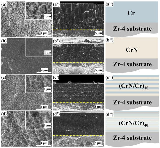
Figure 1.
Surface and cross-sectional morphology of different coatings and their structural schematics (the yellow dotted line shows the separation between the coating and the substrate.): (a–a’’) Cr coating, (b–b’’) CrN coating, (c–c’’) (CrN/Cr)10 coating, (d–d’’) (CrN/Cr)40 coating.
Figure 1a’–d’ shows the cross-sectional microstructures of Cr, CrN, and CrN/Cr multi-layer coatings. All coatings are uniform in thickness across their cross-section, the coatings are free of defects such as holes and cracks, and the interface between the coating and the substrate is smooth. The thickness of the single-layer Cr coating is ~10 μm, and the microstructure is dense with a coarse columnar crystal structure. The single-layer CrN coating, on the other hand, has an elongated columnar crystal structure with no obvious grain boundaries and a denser structure. For multi-layer coatings, it can be observed that each layer of the multi-layer coating has a clear demarcation line, and the coating has an elongated columnar crystal structure, which is due to the fact that CrN and Cr have the same crystal structure and are both cubic phases. As shown in Figure 1d′, the columnar crystal structure cannot be clearly observed in this section as the number of layers increases. This phenomenon is due to the increase in switching frequency, the metal layer and ceramic layer transition with each other, the original columnar crystal structure by the composition of change and growth stopping and re-nucleation, so that grain growth is forced to interrupt the refinement, and with the increase in the cycle, the effect of grain refinement is more obvious, and the coating becomes more compact and dense.
Figure 2 displays the XRD patterns of Cr, CrN, and (CrN/Cr)n multi-layer coatings, where Cr(200) crystal facets (PDF#85-1336) are selectively oriented for bcc-Cr monolayer coatings and CrN(111) crystal facets (PDF#76-2494) are selectively oriented for fcc-CrN monolayer coatings. For the multi-layer coatings, three phases of Cr, CrN, and Cr2N appeared, where the appearance of Cr2N (PDF#35-0803) may be due to the conversion of a small amount of CrN to Cr2N caused by stress relief within the CrN/Cr coating system [22,31]. It is easy to see that the diffraction peak intensities of the CrN/Cr multi-layer coatings show significant attenuation, and the more layers there are, the lower the diffraction peak intensities are, indicating that the coatings are weakly crystalline, and the grain sizes are gradually decreasing. In addition, the preferential orientation of the Cr layer shifted from (200) to (110). Grain refining brought on by an increase in the number of layers may be the cause of the shift in the favoured growth of Cr. The lowest strain energy plane is where the chosen grain orientation grows preferentially. The coating primarily forms on the (110) plane, which is parallel to the surface, because the Cr(110) plane is a low-energy densely packed plane.
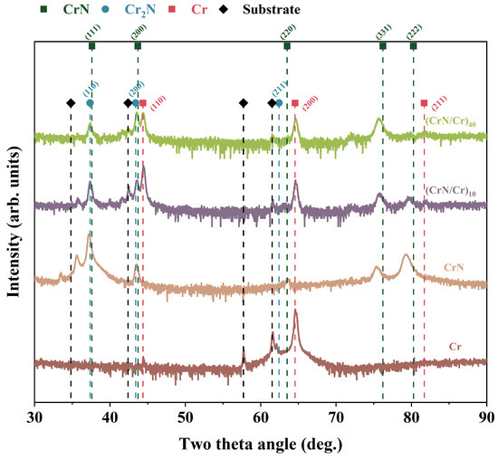
Figure 2.
XRD patterns of Cr, CrN, and (CrN/Cr)n multi-layer coatings.
3.2. Mechanical Properties of the Different Coatings as Deposited
Nanoindentation was used to assess the coatings’ nanohardness(H) and elastic modulus(E). The nanohardness and elastic modulus of single-layer Cr, single-layer CrN, and (Cr/CrN)n multi-layer coatings are displayed in Figure 3a, with Figure 3b displaying the coatings’ H and E, H3, and E2 ratios. We made sure the indentation depth in these tests was less than 10% of the coating’s overall thickness. Among them, the CrN coating is a hard coating with a nanohardness of 20.86 GPa, which is much higher than the metallic Cr coating (3.26 Gpa). For multi-layer coatings, with an increasing number of layers, coating hardness increased from 8.0 GPa to 12.3 GPa and mean elastic modulus increased from 296.0 GPa to 356.4 GPa, a phenomenon that can be attributed to the fact that multi-layer coatings usually improve in terms of hardness, adhesion, wear, and corrosion resistance [35]. It has been shown that the high hardness and fracture toughness of multi-layer coatings are mainly due to the growth of two materials with different elastic modulus on the surfaces of each other, the small widths of the interlayer (semi)lattice interfaces and the transition interfaces between the two sub-layers, the alternating stresses within the coatings, and the interfacial stresses at the lattice interfaces, which have the effect of preventing dislocations from crossing the grain boundaries [36]. Consequently, in the relatively softer sub-layers, slip over dislocations is suppressed by the interface, and the final layer exhibits strengthening [37,38]. The hardness and elastic modulus of the CrN/Cr multi-layer coatings show a decreasing trend compared to the CrN monolayer coatings, and this phenomenon may be due to the fact that the Cr interlayer is a soft phase with a softer texture, and the Cr layer counteracts the contribution of hardness from the CrN fine grain reinforcement. In addition, the H/E ratio is commonly used to assess the plastic deformation resistance and abrasion resistance of coatings [39,40], while the H3/E2 ratio is proportional to the yield stress of the material and can be used as an indicator of the toughness of the coating. It is worth noting that the values of H/E and H3/E2 for single-layer Cr coatings and (CrN/Cr)n multi-layer coatings in this study are lower than those for CrN, as shown in Figure 3b, indicating that CrN coatings have poor toughness and may be susceptible to budding cracks during steam oxidation at a high temperature
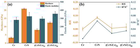
Figure 3.
Mechanical properties of Cr, CrN, and (CrN/Cr)n multi-layer coatings: (a) hardness (H) and elastic modulus (E), (b) H/E, H3/E2.
The optical pictures of the scratch tracks of the Cr, CrN, and (CrN/Cr)n multi-layer coatings coated on the Zr-4 alloy are displayed in Figure 4. The scratch test was used to assess the coatings’ bond strength to the substrate. The single Cr coating had the lowest crack resistance, as seen in Figure 4a. This could be because the Cr coating has a lower H/E value, as seen in Figure 3b. There was fracture propagation and mild spalling when the load was raised to 38.7 N. The coating separated from the substrate when the load was raised to 45.7 N. In Figure 4b, the CrN coating starts to peel off at the edge of the scratch track at a load of 17.5 N. On increasing the load to 28.7 N, the coating peels off, exposing the substrate. For the multi-layer coatings (as shown in Figure 4c,d), it was observed that regular herringbone cracks developed on both sides of the scratch track with increasing load, with two layers of (CrN/Cr)n coatings failing completely at loads of 42.7 N and 61.3 N, respectively, exposing the substrate. It is evident that a coating’s binding is stronger, the more layers it contains. The inclusion of the multi-layer structure is conducive to lowering the stress concentration of the CrN layer under scratch loading, which is why the bond strength of (CrN/Cr)n multi-layer coatings is stronger according to the results of scratch testing [41]. Furthermore, the multi-layer structure’s interfacial action can successfully stop cracks from spreading, strengthening the coating’s a bond [42].
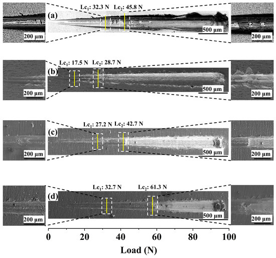
Figure 4.
Optical images of scratching profiles of different coatings: (a) Cr coating, (b) CrN coating, (c) (CrN/Cr)10 coating, and (d) (CrN/Cr)40 coating. (Note: The solid yellow lines show the critical loads at different stages of the scratch test and the white dashed box shows the magnified area).
3.3. High-Temperature Steam Oxidation Resistance
The time–weight gain curves of Cr, CrN, and their (CrN/Cr)n multi-layer coatings were recorded for high-temperature steam oxidation at 1200 °C for 1 h, as shown in Figure 5, in order to compare the resistance of different coating structures to high-temperature steam oxidation. It can be observed that Zr-4 alloy has a typical parabolic weight gain curve at high-temperature steam oxidation, and its total weight gain is 82.45 mg/cm2. For the coated samples, the weight increase and evolution can be divided into three processes, namely, protective state, transitional state, and unprotected state. Among them, the weight gain in the protected state is parabolic; the transition state is linear weight gain; the unprotected state shows a growth rate. The total weight gain of the four coatings was 21.14 mg/cm2 for Cr, 55.16 mg/cm2 for CrN, 19.50 mg/cm2 for (CrN/Cr)10, and 13.40 mg/cm2 for (CrN/Cr)40. The results show that the oxidation rate of all coated samples is significantly lower compared to the uncoated Zr-4 substrate. Of these, the CrN coating is less effective in resisting high-temperature steam oxidation and is relatively quickly unprotected. Several studies have shown that multi-layer structures can effectively reduce stress concentration, prevent crack propagation, and improve the overall performance of the coating [42,43]. For this reason, multi-layer coatings have a lower total weight gain; the more layers, the lower the total weight gain, even lower than single-layer Cr coatings (21.14 mg/cm2), showing performance-enhancing effects. This may be due to the fact that the higher the number of layers, the more continuous the crystallinity of the coating and the smaller the grain size, resulting in higher oxidation kinetics with a higher number of interfaces [19,25,44]. Therefore, the (CrN/Cr)40 coating shows better resistance to high-temperature steam oxidation.
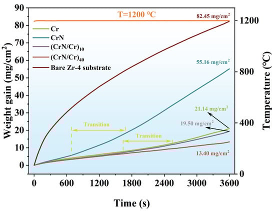
Figure 5.
High-temperature steam weight gain curves for different coatings.
Figure 6 shows the XRD patterns of Cr, CrN, and their (CrN/Cr)n multi-layer coatings after oxidation at 1200 °C in a steam environment for 1 h. The results show that strong Cr2O3 diffraction peaks (PDF#82-1484) are present after oxidation. These are the main products of coating oxidation. In particular, the CrN coating decomposed after steam oxidation at a high temperature, showing strong Cr(110) diffraction peaks, and weak Cr(200) diffraction peaks were detected, indicating that CrN had completely decomposed to form Cr and oxidised to form Cr2O3. At the same time, the ZrO2 diffraction peak (PDF#37-1484) signals were detected, indicating that the coatings had lost their protective effect on the substrate, a phenomenon evidenced by their weight gain curves. For the multi-layer coatings (CrN/Cr)10 and (CrN/Cr)40, only Cr2O3 diffraction peaks were detected. It has been shown that CrN decomposes to Cr2N at ~1000 °C and further dissociates to Cr and N atoms at 1120 °C (Equations (1) and (2) show its decomposition reaction [22,31,32]). Therefore, at 1200 °C in a steam environment, CrN decomposes completely to Cr, which is then oxidised by the steam.
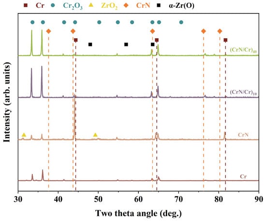
Figure 6.
XRD patterns of various coatings after high-temperature steam oxidation.
Figure 7 shows the SEM cross-sectional morphology and EDS elemental distribution of Cr, CrN, and their (CrN/Cr)n multi-layer coatings after oxidation at 1200 °C for 1 h in a steam environment. Oxidation of the Cr coatings shows a thick oxide layer accompanied by the formation of a large number of pores, which may be related to the generation of volatile CrO3 [45] and CrO2(OH)2 [14,46]. Equations (3) and (4) display the pertinent reaction equations. It was also seen that O did not permeate into the Zr-4 alloy substrate. This implies that the inward transport of O atoms is successfully inhibited by the Cr2O3 oxide layer that forms. Zr diffusion channels were seen in the Cr layer, but they did not seem to spread out over a wide region. For the CrN single-layer coating (Figure 7b), the coating loses its protective effect on the substrate after high-temperature steam oxidation, and the mapping diagram shows that oxygen has diffused into the substrate. The complete disappearance of the boundary between the CrN and Zr-4 substrate is due to the severe oxidation caused by the poor protection of the CrN coating, and the severe outward diffusion of Zr atoms occurs, and this phenomenon may be due to the fact that the CrN is prone to cracking and spalling in high-temperature environments, which provides a channel for Zr diffusion [47]. The CrN layer (Figure 8b) only weakly detected the N element because the CrN coating decomposes into Cr2N at 1000 °C, and as the temperature rises, Cr2N continues to decompose into Cr and N2. Part of the N2 gas produced by its decomposition escapes to the outside [11] and diffuses inwards to form α-Zr(N) [11,26].
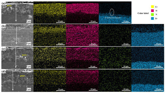
Figure 7.
Cross-sectional SEM morphology and mapping of different coatings via high-temperature steam oxidation at 1200 °C for 1 h: (a) Cr coating, (b) CrN coating, (c) (CrN/Cr)10 coating, and (d) (CrN/Cr)40 coating.
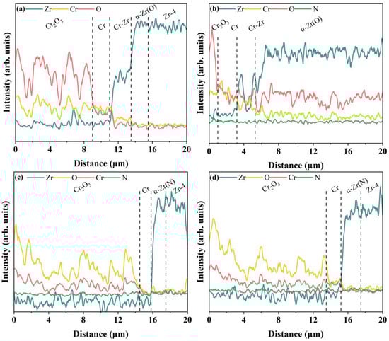
Figure 8.
Cross-sectional EDS line scan of different coatings via high-temperature steam oxidation at 1200 °C for 1 h: (a) Cr coating, (b) CrN coating, (c) (CrN/Cr)10 coating, and (d) (CrN/Cr)40 coating.
For multi-layer coatings (Figure 7c,d), the multi-layer interface completely disappears after oxidation, a phenomenon due to the gradual decomposition of CrN into metallic Cr under high-temperature conditions, which fuses with the original metallic Cr layer (Equations (1) and (2)). According to the EDS results, the layering of Zr and Cr is more obvious, and there is no obvious Cr-Zr interdiffusion layer. In addition, we found that pores also exist in the multi-layer coating after high-temperature steam oxidation, which is caused by the gradual decomposition of the CrN layer into Cr when nitrogen is generated, and because the outer layer has formed a dense oxide layer, N atoms cannot escape but can only collect in the oxide layer to form pores. The formation of this pore destroys the integrity of the oxide layer, and as the exposure time in the environment of the water loss accident increases, it can become a fast channel for the inward diffusion of O atoms. Meanwhile, elemental N signals were detected in both substrate regions (Figure 8c,d), and the N vacancies close to the substrate may induce Zr atoms to diffuse into the coating by forming a dense Cr2O3 layer on the surface of the coating, where the further diffusion of O into these pores is reduced. Additionally, at high temperatures, the high diffusion coefficient of nitrogen in Zr causes a β-Zr to α-Zr(N) phase change when N diffuses into the substrate. This prevents Cr-Zr interdiffusion since Cr has lower diffusion kinetics and is less soluble in α-Zr than in β-Zr. [26].
For the monolayer Cr coating, the outward diffusion of Zr was not pronounced according to SEM images (Figure 7) and EDS scan data (Figure 8). However, for the single-layer CrN coating, a certain intensity of O was found close to the substrate, indicating that oxygen migrated into the substrate and caused an α-Zr(O) solid solution to develop. Although a tiny quantity of oxygen signal was detected from the substrate for the multi-layer coatings, it was far less than the coating’s oxygen concentration. Particularly, N signals were found close to the substrate.
3.4. Evolution of Different Coatings During Steam Oxidisation Process
To investigate the properties of different coatings after steam oxidation at 1200 °C for 1 h, the evolution of Cr, CrN, and (CrN/Cr)n multi-layer coatings was compared with the model shown schematically in Figure 9. The oxidation behaviour of single-layer Cr coatings at 1200 °C is shown in Figure 9a. As the oxidising process begins, O is diffusing along the grain boundaries of Cr, reacting with Cr to form a dense layer of Cr2O3 that acts as an oxygen diffusion barrier, effectively blocking the diffusion of O inwards. As the oxidation time progresses, the oxide layer reacts with water vapour and oxygen to form volatile CrO2(OH)2 [14,46] and CrO3 [45], producing numerous pores in all coatings. In addition, small amounts of outwardly diffusing Zr will react with inwardly diffusing oxygen to form ZrO2, which precipitates in the Cr grain boundaries. The ZrO2 channels provide a rapid route for oxygen diffusion into the substrate, which may lead to a build-up of oxygen concentration in the vicinity of the substrate, resulting in the formation of oxygen-stabilised α-Zr(O) [7]. As the outwardly diffusing Zr diffuses to the Cr2O3/Cr interface, it re-exports Cr, increasing the thickness of the Cr layer and decreasing the thickness of the Cr2O3 layer. At this stage, the ZrO2 channel plays an important role as the major route for oxygen diffusion. The nucleation of ZrO2 in the substrate and the oxidation of the substrate result from the O concentration reaching the solubility limit of O in the Zr-4 substrate, which finally causes the Cr coating to fail.
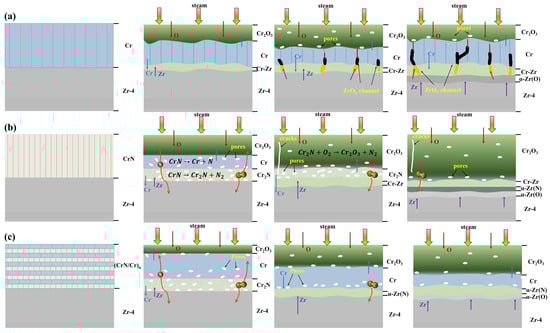
Figure 9.
Schematic representation of the evolution of 1200 °C vapour oxidation in different coatings: (a) Cr coating, (b) CrN coating, and (c) (CrN/Cr)n multi-layer coating.
For a single-layer CrN coating (shown in Figure 9b), oxidation begins when the outermost CrN reacts with H2O to form an oxide layer. In addition, the inner CrN decomposes into Cr2N or Cr, producing N. The produced N escapes upwards and diffuses downwards, accumulating under the oxide layer and forming pores. As the oxidation time increases, a layer of α-Zr(N) is formed as the downward diffusing N diffuses into the vicinity of the substrate. Furthermore, cracking may result from the high coefficient of thermal expansion between Zr and CrN. The discrepancy in density between CrN and Cr2N can also cause cracks in the coating during the CrN breakdown process [48]. Cracks speed up substrate fail by allowing oxygen to infiltrate quickly into the coating and Zr to diffuse out.
For (CrN/Cr)n multi-layer coatings (shown in Figure 9c), at the onset of oxidation, the CrN and Cr in the outer layer oxidise rapidly to form Cr2O3. At the same time, CrN decomposes into Cr2N or Cr, releasing N. Since the outer layer has formed a dense oxide layer, the N atoms cannot escape and can only collect in the oxide layer to form pores. These pores have the potential to become fast channels for O atoms to diffuse inwards. With the prolongation of oxidation time, when N diffuses into the coating/substrate interface, it will preferentially form an α-Zr(N) layer with Zr, thus blocking Cr-Zr interdiffusion. Furthermore, because the multi-layer coatings lower interfacial stress and inhibit cracking, no cracks resembling those seen in the CrN coatings (Figure 9b) were seen.
4. Conclusions
The HiPIMS method was utilised to deposit Cr coating, CrN coating, and (Cr/CrN)n multi-layer coatings on the Zr-4 alloy surface. A thorough investigation was conducted into how various coating architectures affected the coatings’ mechanical characteristics, microstructure, and resistance to high-temperature steam oxidation. The conclusions that followed were as follows:
Cr coatings, CrN coatings, and (CrN/Cr)n multi-layer coatings prepared by HiPIMS technology showed a coarse columnar crystal structure in the deposited Cr coating layer and a fine columnar crystal structure in the CrN coating, while the multi-layer coatings showed a smoother surface and a finer grain size growth structure. The XRD peak intensities showed a significant weakening, and the more layers there were, the lower the diffraction peak intensities were, indicating the weaker crystallinity of the coatings and the gradual decrease in grain size. In addition, the preferred orientation of the Cr layer shifted from (200) to (110). The shift in the preferred growth of Cr may be due to grain refinement caused by the increase in the number of layers, where the desired grain orientation preferentially grows along the plane with the lowest strain energy.
The as-deposited coating mechanical properties test results showed that the nanohardness of the CrN single layer was 20.86 GPa, much higher than that of the metallic Cr coating (3.26 GPa). As the number of layers in the multi-layer coating increased, the coating’s nanohardness rose from 8.0 GPa to 12.3 GPa, and its average elastic modulus increased from 296.0 GPa to 356.4 GPa. The (CrN/Cr)40 plating is more bondable than the single-layer plating, and the introduction of the multi-layer structure makes it easier to reduce the stress concentration in the CrN layer under the effect of scratching. Furthermore, the interface effect of the multi-layer structure can effectively inhibit crack propagation, thus improving the mechanical properties of the coating.
In the high-temperature steam oxidation environment at 1200 °C, all deposited coatings demonstrated better oxidation resistance than the bare Zr-4 alloys. After oxidation, the Cr coatings formed a thicker oxide layer, the CrN coatings were prone to cracking and spalling, and the (Cr/CrN)n multi-layer coatings showed the least oxidative weight gain and the best integrity. Excellent resistance to high-temperature steam oxidation is exhibited by the (Cr/CrN)n coating with a multi-layer structure design. Additionally, the multi-layer structure can be used to effectively release the internal stress of the coating, thereby reducing the likelihood of cracking after high-temperature steam oxidation. Furthermore, the CrN layer breaks down into Cr2N and N2 during the oxidation process, and when N diffuses into the substrate, a thin layer of α-Zr(N) forms. This effectively restricts the mutual diffusivity of Cr and Zr and prevents O from diffusing into the substrate.
Author Contributions
Conceptualization, W.D.; methodology, W.D.; software, D.L. and D.C.; validation, W.D., Q.W., and J.Y.; formal analysis, D.L. and D.C.; investigation, D.L. and D.C.; resources, W.D. and J.Y.; data curation, D.L. and D.C.; writing—original draft preparation, D.L. and D.C.; writing—review and editing, D.C. and W.D.; visualisation, W.D.; supervision, W.D., Q.W., J.Y., and J.W.; project administration, W.D.; funding acquisition, W.D. and J.W. All authors have read and agreed to the published version of the manuscript.
Funding
This work is supported by Dongguan Key Research and Development Program, China (No. 20221200300032).
Institutional Review Board Statement
Not applicable.
Informed Consent Statement
Not applicable.
Data Availability Statement
The data used to support the findings of this study are available from the corresponding author upon request.
Conflicts of Interest
Jun Yan was employed by China Nuclear Power Technology Research Institute Co., Ltd., Shenzhen. Junfeng Wang was employed by Guangdong Dtech Technology Co., Ltd., Dongguan. The remaining authors declare that the research was conducted in the absence of any commercial or financial relationships that could be construed as potential conflicts of interest.
References
- Kim, T.; Kim, J.; Choi, K.J.; Yoo, S.C.; Kim, S.; Kim, J.H. Phase transformation of oxide film in zirconium alloy in high temperature hydrogenated water. Corros. Sci. 2015, 99, 134–144. [Google Scholar] [CrossRef]
- Yang, H.L.; Kano, S.; McGrady, J.; Chen, D.Y.; Murakami, K.; Abe, H. Microstructural evolution and hardening effect in low-dose self-ion irradiated Zr–Nb alloys. J. Nucl. Mater. 2020, 542, 152523. [Google Scholar] [CrossRef]
- Yang, J.; Wang, B.; Hu, S.; Zhao, F.; Han, B.; Shang, L.; Cui, Y.; Wang, S.; Yun, D.; Xu, D. Microstructural understanding of CrN layer as a barrier against Cr-Zr interdiffusion in Cr-coated zirconium alloy for accident tolerant fuel claddings. Mater. Charact. 2023, 205, 113242. [Google Scholar] [CrossRef]
- Duan, Z.; Yang, H.; Satoh, Y.; Murakami, K.; Kano, S.; Zhao, Z.; Shen, J.; Abe, H. Current status of materials development of nuclear fuel cladding tubes for light water reactors. Nucl. Eng. Des. 2017, 316, 131–150. [Google Scholar] [CrossRef]
- Kurata, M. Research and Development Methodology for Practical Use of Accident Tolerant Fuel in Light Water Reactors. Nucl. Eng. Technol. 2016, 48, 26–32. [Google Scholar] [CrossRef]
- Koo, Y.-H.; Yang, J.-H.; Park, J.-Y.; Kim, K.-S.; Kim, H.-G.; Kim, D.-J.; Jung, Y.-I.; Song, K.-W. KAERI’s Development of LWR Accident-Tolerant Fuel. Nucl. Technol. 2017, 186, 295–304. [Google Scholar] [CrossRef]
- Liu, J.; Steinbrück, M.; Große, M.; Stegmaier, U.; Tang, C.; Yun, D.; Yang, J.; Cui, Y.; Seifert, H.J. Systematic investigations on the coating degradation mechanism during the steam oxidation of Cr-coated Zry-4 at 1200 °C. Corros. Sci. 2022, 202, 110310. [Google Scholar] [CrossRef]
- Li, W.; Wang, Z.; Shuai, J.; Xu, B.; Wang, A.; Ke, P. A high oxidation resistance Ti2AlC coating on Zirlo substrates for loss-of-coolant accident conditions. Ceram. Int. 2019, 45, 13912–13922. [Google Scholar] [CrossRef]
- Richardson, P.; Cuskelly, D.; Brandt, M.; Kisi, E. Microstructural analysis of in-situ reacted Ti2AlC MAX phase composite coating by laser cladding. Surf. Coat. Technol. 2020, 385, 125360. [Google Scholar] [CrossRef]
- Li, Z.; Wang, Z.; Ma, G.; Chen, R.; Yang, W.; Wang, K.; Ke, P.; Wang, A. High-performance Cr2AlC MAX phase coatings for ATF application: Interface design and oxidation mechanism. Corros. Commun. 2024, 13, 27–36. [Google Scholar] [CrossRef]
- Liu, J.; Hao, Z.; Cui, Z.; Ma, D.; Lu, J.; Cui, Y.; Li, C.; Liu, W.; Xie, S.; Hu, P.; et al. Oxidation behavior, thermal stability, and the coating/substrate interface evolution of CrN-coated Zircaloy under high-temperature steam. Corros. Sci. 2021, 185, 109416. [Google Scholar] [CrossRef]
- Chen, Q.S.; Liu, C.H.; Zhang, R.Q.; Yang, H.Y.; Wei, T.G.; Wang, Y.; Li, Z.; He, L.X.; Wang, J.; Wang, L.; et al. Microstructure and high-temperature steam oxidation properties of thick Cr coatings prepared by magnetron sputtering for accident tolerant fuel claddings: The role of bias in the deposition process. Corros. Sci. 2020, 165, 108378. [Google Scholar] [CrossRef]
- Kashkarov, E.B.; Sidelev, D.V.; Syrtanov, M.S.; Tang, C.; Steinbrück, M. Oxidation kinetics of Cr-coated zirconium alloy: Effect of coating thickness and microstructure. Corros. Sci. 2020, 175, 108883. [Google Scholar] [CrossRef]
- Ma, H.-B.; Yan, J.; Zhao, Y.-H.; Liu, T.; Ren, Q.-S.; Liao, Y.-H.; Zuo, J.-D.; Liu, G.; Yao, M.-Y. Oxidation behavior of Cr-coated zirconium alloy cladding in high-temperature steam above 1200 °C. npj Mater. Degrad. 2021, 5, 7. [Google Scholar] [CrossRef]
- Meng, Y.; Zeng, S.; Teng, Z.; Han, X.; Zhang, H. Control of the preferential orientation Cr coatings deposited on zircaloy substrates and study of their oxidation behavior. Thin Solid Film. 2021, 730, 138699. [Google Scholar] [CrossRef]
- Wang, W.; Zhang, G.; Wang, C.; Wang, T.; Zhang, Y.; Xin, T. Investigations on 1200 °C steam oxidation behavior of Cr coatings with distinct crystallographic orientation on Zircaloy-4 alloys. J. Nucl. Mater. 2024, 592, 154945. [Google Scholar] [CrossRef]
- Yeom, H.; Johnson, G.; Maier, B.; Dabney, T.; Sridharan, K. High temperature oxidation of cold spray Cr-coated accident tolerant zirconium-alloy cladding with Nb diffusion barrier layer. J. Nucl. Mater. 2024, 588, 154822. [Google Scholar] [CrossRef]
- Park, D.J.; Kim, H.G.; Park, J.Y.; Jung, Y.I.; Park, J.H.; Koo, Y.H. A study of the oxidation of FeCrAl alloy in pressurized water and high-temperature steam environment. Corros. Sci. 2015, 94, 459–465. [Google Scholar] [CrossRef]
- Brachet, J.-C.; Rouesne, E.; Ribis, J.; Guilbert, T.; Urvoy, S.; Nony, G.; Toffolon-Masclet, C.; Le Saux, M.; Chaabane, N.; Palancher, H.; et al. High temperature steam oxidation of chromium-coated zirconium-based alloys: Kinetics and process. Corros. Sci. 2020, 167, 108537. [Google Scholar] [CrossRef]
- Wang, W.; Zhang, G.; Wang, C.; Wang, T.; Zhang, Y.; Xin, T. Construction of Cr coatings with different columnar structure on Zircaloy-4 alloys to optimize the high-temperature steam oxidation behavior for accident tolerant fuel claddings. J. Alloys Compd. 2023, 946, 169385. [Google Scholar] [CrossRef]
- Han, Z.; Wang, Z.; Wang, Z.; Tan, S.; Wang, A.; Piao, Z.; Ke, P. Tailored high-temperature corrosion behavior of Cr coatings using high power impulse magnetron sputtering on ZIRLO alloys for accident-tolerant fuel application. Surf. Coat. Technol. 2024, 488, 130941. [Google Scholar] [CrossRef]
- Yang, J.; Shang, L.; Sun, J.; Bai, S.; Wang, S.; Liu, J.; Yun, D.; Ma, D. Restraining the Cr-Zr interdiffusion of Cr-coated Zr alloys in high temperature environment: A Cr/CrN/Cr coating approach. Corros. Sci. 2023, 214, 111015. [Google Scholar] [CrossRef]
- Li, B.; Shen, J.; Yang, Z.; Yang, H.; Kano, S.; Abe, H. Interfacial evolution in Cr/Mo-coated Zr alloys near the Mo-Zr eutectoid temperature. J. Nucl. Mater. 2025, 603, 155406. [Google Scholar] [CrossRef]
- Zhong, Y.; Gao, S.; Zhao, S.; Gui, X.; Zhai, L.; Huang, M.; Chen, P.; Yin, C.; He, L.; Yang, J.; et al. Effect of Mo interlayer on the diffusion behavior and mechanical property of Cr-coated Zr alloy cladding tubes. Mater. Today Commun. 2024, 41, 110393. [Google Scholar] [CrossRef]
- Liu, J.; Hao, Z.; Cui, Z.; Ma, D.; Lu, J.; Cui, Y.; Li, C.; Liu, W.; Xie, S.; Huang, P.; et al. Investigation of the oxidation mechanisms of superlattice Cr-CrN/TiSiN-Cr multilayer coatings on Zircaloy substrates under high-temperature steam atmospheres. Corros. Sci. 2021, 192, 109782. [Google Scholar] [CrossRef]
- Sidelev, D.V.; Ruchkin, S.E.; Syrtanov, M.S.; Kashkarov, E.B.; Shelepov, I.A.; Malgin, A.G.; Polunin, K.K.; Stoykov, K.V.; Mokrushin, A.A. Protective Cr coatings with CrN/Cr multilayers for zirconium fuel claddings. Surf. Coat. Technol. 2022, 433, 128131. [Google Scholar] [CrossRef]
- Xu, C.; Wang, X.; Zhou, Q.; Xue, W.; Jin, X.; Du, J.; Li, Y.; Li, S. TEM characterizations of a ZrO2/Cr composite coating on Zr-1Nb alloy after 1200 °C steam oxidation. Mater. Charact. 2023, 197, 112701. [Google Scholar] [CrossRef]
- Xiang, Y.; Liu, C.; Li, Z.; Liu, H.; Yang, J.; Yang, H.; Zhang, R.; He, L.; Liu, J.; Long, J.; et al. Interface stability and microstructural evolution of the (Cr/CrN)24-coated zirconium alloy under different thermal shock temperatures. Surf. Coat. Technol. 2022, 429, 127947. [Google Scholar] [CrossRef]
- Li, Z.; Li, Y.; Liu, S.; Wu, L.; Qin, W.; Wu, X. Enhancement of oxidation resistance of Cr/CrN composite coating on Zr-4 surface by high lattice-matched interfacial Engineering. J. Nucl. Mater. 2023, 574, 154162. [Google Scholar] [CrossRef]
- Musil, J. Flexible hard nanocomposite coatings. RSC Adv. 2015, 5, 60482–60495. [Google Scholar] [CrossRef]
- Meng, C.; Ma, J.; Wang, H.; Liu, W.; Hu, Y.; Zhang, B.; Tu, M.; Yuan, C.; He, X. Enhancing the oxidation behaviors of Zr alloys for nuclear fuel cladding using nanolamellar Cr/CrN coating. Corros. Sci. 2024, 227, 111725. [Google Scholar] [CrossRef]
- Li, Z.; Liu, C.; Chen, Q.; Yang, J.; Liu, J.; Yang, H.; Zhang, W.; Zhang, R.; He, L.; Long, J.; et al. Microstructure, high-temperature corrosion and steam oxidation properties of Cr/CrN multilayer coatings prepared by magnetron sputtering. Corros. Sci. 2021, 191, 109755. [Google Scholar] [CrossRef]
- Chen, D.; Dai, W.; Liang, D.; Wang, Q.; Yan, J. Mechanical and high-temperature steam oxidation properties of Cr coatings deposited via high-power impulse magnetron sputtering. J. Nucl. Mater. 2025, 603, 155482. [Google Scholar] [CrossRef]
- de Monteynard, A.; Schuster, F.; Billard, A.; Sanchette, F. Properties of chromium thin films deposited in a hollow cathode magnetron powered by pulsed DC or HiPIMS. Surf. Coat. Technol. 2017, 330, 241–248. [Google Scholar] [CrossRef]
- Stueber, M.; Holleck, H.; Leiste, H.; Seemann, K.; Ulrich, S.; Ziebert, C. Concepts for the design of advanced nanoscale PVD multilayer protective thin films. J. Alloys Compd. 2009, 483, 321–333. [Google Scholar] [CrossRef]
- Wagner, A.; Holec, D.; Mayrhofer, P.H.; Bartosik, M. Enhanced fracture toughness in ceramic superlattice thin films: On the role of coherency stresses and misfit dislocations. Mater. Des. 2021, 202, 109517. [Google Scholar] [CrossRef]
- Chu, X.; Barnett, S.A. Model of superlattice yield stress and hardness enhancements. J. Appl. Phys. 1995, 77, 4403–4411. [Google Scholar] [CrossRef]
- Yashar, P.C.; Sproul, W.D. Nanometer scale multilayered hard coatings. Vacuum 1999, 55, 179–190. [Google Scholar] [CrossRef]
- Leyland, A.; Matthews, A. On the significance of the H/E ratio in wear control: A nanocomposite coating approach to optimised tribological behaviour. Wear 2000, 246, 1–11. [Google Scholar] [CrossRef]
- Beake, B.D. The influence of the H/E ratio on wear resistance of coating systems – Insights from small-scale testing. Surf. Coat. Technol. 2022, 442, 128272. [Google Scholar] [CrossRef]
- Cai, X.; Gao, Y.; Cai, F.; Zhang, L.; Zhang, S. Effects of multi-layer structure on microstructure, wear and erosion performance of the Cr/CrN films on Ti alloy substrate. Appl. Surf. Sci. 2019, 483, 661–669. [Google Scholar] [CrossRef]
- Holmberg, K.; Ronkainen, H.; Matthews, A. Tribology of thin coatings. Ceram. Int. 2000, 26, 787–795. [Google Scholar] [CrossRef]
- Wieciński, P.; Smolik, J.; Garbacz, H.; Kurzydłowski, K.J. Failure and deformation mechanisms during indentation in nanostructured Cr/CrN multilayer coatings. Surf. Coat. Technol. 2014, 240, 23–31. [Google Scholar] [CrossRef]
- Brachet, J.-C.; Idarraga-Trujillo, I.; Flem, M.L.; Saux, M.L.; Vandenberghe, V.; Urvoy, S.; Rouesne, E.; Guilbert, T.; Toffolon-Masclet, C.; Tupin, M.; et al. Early studies on Cr-Coated Zircaloy-4 as enhanced accident tolerant nuclear fuel claddings for light water reactors. J. Nucl. Mater. 2019, 517, 268–285. [Google Scholar] [CrossRef]
- Arifin, S.K.; Hamid, M.; Berahim, A.N.; Ani, M.H. Effects of water vapor on protectiveness of Cr2O3 scale at 1073 K. IOP Conf. Ser. Mater. Sci. Eng. 2018, 290, 012085. [Google Scholar] [CrossRef]
- Deng, J.; Geng, D.; Sun, Q.; Song, Z.; Sun, J. Steam oxidation of Cr-coated zirconium alloy claddings at 1200 °C: Kinetics transition and failure mechanism of Cr coatings. J. Nucl. Mater. 2023, 586, 154684. [Google Scholar] [CrossRef]
- Liu, J.; Cui, Z.; Ma, D.; Lu, J.; Cui, Y.; Li, C.; Liu, W.; Hao, Z.; Hu, P.; Yao, M.; et al. Investigation of oxidation behaviors of coated Zircaloy as accident-tolerant fuel with CrAlN and CrAlSiN coatings in high-temperature steam. Corros. Sci. 2020, 175, 108896. [Google Scholar] [CrossRef]
- Krejčí, J.; Kabátová, J.; Manoch, F.; Kočí, J.; Cvrček, L.; Málek, J.; Krum, S.; Šutta, P.; Bublíková, P.; Halodová, P.; et al. Development and testing of multicomponent fuel cladding with enhanced accidental performance. Nucl. Eng. Technol. 2020, 52, 597–609. [Google Scholar] [CrossRef]
Disclaimer/Publisher’s Note: The statements, opinions and data contained in all publications are solely those of the individual author(s) and contributor(s) and not of MDPI and/or the editor(s). MDPI and/or the editor(s) disclaim responsibility for any injury to people or property resulting from any ideas, methods, instructions or products referred to in the content. |
© 2025 by the authors. Licensee MDPI, Basel, Switzerland. This article is an open access article distributed under the terms and conditions of the Creative Commons Attribution (CC BY) license (https://creativecommons.org/licenses/by/4.0/).