Abstract
Surface acoustic wave-based (SAW) sensors are of great interest due to their high sensibility and fast and stable responses. They can be obtained at an overall low cost and with an intuitive and easy-to-use method. The chemical sensitization of a piezoelectric transducer plays a key role in defining the properties of SAW sensors. In this study, we investigate the structural and adhesion properties of a new class of coating material based on polyurethane polymeric composites. We used dark-field microscopy (DFM) and scanning electron microscopy (SEM) to observe the microstructure of polyurethane composite coatings on piezoelectric sensor elements and to analyze the effects of the chemical resistance and adhesion test (CAT) on the coating layers obtained with the polyurethane polymeric composites. The results of the microscopy showed that all polyurethane composite coatings exhibited excellent uniformity and stability after chemical adherence testing (CAT). All of the observations were correlated with the results of the ultrasonic analysis, which demonstrated the role of polyurethane as a binder to form the stable structure of the composites and, at the same time, as an adhesion promoter, increasing the chemical resistance and the adherence of the coating layer to the complex surface of the piezoelectric sensor element.
1. Introduction
Surface acoustic chemical (SAW) sensors have been investigated widely in recent years [1,2] due to their high sensibility, simplicity, and overall low cost in many aspects. The performance of SAW technology relies on two principal factors: First, the hardware design is responsible for the electronics on which the sensibility of the chemical transducing and the stability and precision of the sensor answer depends. And the second principal factor is the sensing interface, which will define the chemical environment that will provide the affinity towards the desired analytes [3]. In SAW technology, the sensing interface is achieved by the deposition of a suitable sensing material, which ideally should present a high affinity and selectivity to the desired analytes, together with the other properties common to all analytical methods, like precision, reproducibility, stability of analytical response, and a suitable lifetime of utilization. As hardware issues have already been conveniently addressed and the state of the art of oscillator circuit development for such high-frequency devices is currently well established, the development of SAW sensor systems that can be turned into real applications still relies on the properties of the sensing interface, and, ultimately, on the choice of the sensitization material together with the coating procedure.
Due to their diverse physical–chemical properties, polymers are materials that have been extensively explored, finding a broad range of applications in several areas. Besides their traditional uses, the vast choice in terms of chemical constitution and peculiar properties also make polymers potential candidates for applications at the molecular level, where they provide many suitable chemical environments and structural properties for several fields [4]. Among others, polymers find applications as drug transporters [5], in the support and design of catalysts [6,7], in sensor applications [8], and as sensing materials for chemical sensors [9]. Polymers enable a broad spectrum of molecular environments suitable for intermolecular interactions with analytes, provided by their diversity of chemical constitutions [10,11,12,13]. Besides their broad diversity of chemical constitutions, their variety of structural properties means that they can work alone as sensing materials or be combined with other components to form functional composites [14,15,16]. Polymers having three-dimensional networks enable the sorption of analytes, providing a high capacity for inclusion and detection by sensor systems [17]. These networks also exhibit suitable mechanical properties, making polymers a promising solution for the sensitization of complex surfaces [18], where they can fulfill most of the necessary requirements of coating materials [19,20,21,22].
In the sensitization of SAW sensors, the expected result of the coating process is the deposition of the desired sensitization material, forming a (usually) nanometric homogeneous layer that accounts for a minimal attenuation of wave propagation and, at the same time, possesses enough material to interact with the available quantity of the analyte, making it suitable for detection and quantification. Finally, the sensing layer should be chemically and mechanically stable for a reasonable lifetime, which is expected for the utilization of sensor systems in real analytical applications. For the coating of a SAW sensor element, some of the methods used include electrospraying, airbrushing, and spin coating [23,24].
Because of their above-mentioned advantages, polymers were used as coating materials at the beginning of the development of SAW sensors [25,26]. However, issues such as dewetting and other problems were reported [27,28,29], leading to a lack of utilization of polymers as sensing materials in recent years.
To address the application of polymers as sensing materials for SAW sensors, we presented a new class of polymeric composites, formed between polyurethane (PU) and a sensing polymer, as sensing materials for SAW technology [30,31]. These new coating materials are intended to take advantage of polymers’ features, such as their cost and availability, along with a robust and efficient coating procedure, resulting in coating layers with increased chemical and mechanical properties compared with the pristine polymers previously used as coating materials. The new coating materials were submitted to CAT to test their chemical and mechanical stability, and the results indicated that, while the coatings of the pristine polymers were almost completely removed from the surface of the SAW sensor element, the coatings with the PU–polymer composites presented a remarkable improvement in chemical resistance and in the adhesion of their coating layers. The results showed that with the PU–polymer composites, although some loss of material was observed, most was retained over the surface, preserving the original sensor responses of their respective sensing polymers and their relative affinities against the tested organic analytes. The observations indicated that the structure of the coating layer of the composites remained over the surface, even after the application of the CAT.
To explain those results, a mechanism for the formation of the PU–polymer composites was proposed, in which the PU is responsible for both the formation of a CAT-resistant polymeric network and the increase in the adhesion of the coating layer to the complex surface of the SAW sensor element. The material loss observed after the CAT should be due to the removal of the sensing polymer units that were eventually not bonded to the composite structure. These free units of sensing polymer should then be washed out from the coating layer by the CAT. The coating layer that remains after the CAT should correspond to the structure of the PU–polymer composite, which presents improved chemical resistance and adhesion in comparison to the pristine polymers as the coating materials. The proposed mechanism of the formation of the PU-composites is schematically represented in Figure 1 and Figure 2.
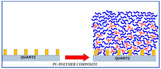
Figure 1.
Representation of the deposition of the PU–polymer composites as the coating material over the SAW sensor element by the spin coating methodology [31]. The blue units represent the molecules of the sensing polymer, and the red ones represent the PU molecules. Some units of the sensing polymer are not involved in the structure of the PU–polymer composite, as is schematically shown at the top of the representation of the coating layer (right side of the figure).
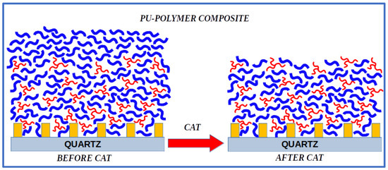
Figure 2.
Schematic representation of the result of the CAT over a coating layer obtained by the deposition of the PU–polymer composites over the SAW sensor element [31]. The blue units represent the molecules of the sensing polymer, and the red ones represent the PU molecules. The units of the sensing polymer that are not bonded to the structure of the PU–polymer composite (seen on the top of the left side of the figure) should be removed from the coating layer by the CAT. The remaining deposited layer should correspond to the structure of the corresponding PU–polymer composite used.
In the present work, three chemically different polymers were combined with PU to form their respective PU–polymer composites: polybutylmethacrylate (PBMA), polylaurylmethacrylate (PLMA), polyisobutylene (PIB). We used DFM [32,33] and SEM to investigate the microstructure of the PU–polymer composite coating layers and the effects of the CAT to analyze the remaining structure of the PU–polymer coating materials over the SAW sensor element. The microscopy results were then correlated with the ultrasonic analysis to characterize the obtained coating layers before and after the CAT of the PU–polymer composites as the sensing materials. The results will provide more insights into the mechanism of formation of the polymeric composites and will characterize the effects of the CAT in the structure of the deposited coating materials. These structural results should be used in a future interpretation of the selectivity and long-term behavior of the sensor responses of the PU composite coating layers.
2. Methodology
2.1. Piezoelectric Sensor Elements
The piezoelectric sensor elements used in this work (Figure 3) are of high polish quartz (SiO2) with a 37.5° cut orientation and dimensions of 4 mm × 8 mm and 0.5 mm thickness. Over the quartz surface, the structure of the interdigital propagators for the acoustic waves and the contact pads, made of gold, were lithographic deposited (SCD Components, Dresden, Germany).
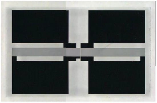
Figure 3.
SAW sensor element with four large contact pads at the edges (in black) and the sensor active area located in the center of the element (the continuous dark gray zone that crosses the whole element horizontally) [34].
2.2. Spin Coating
The spin coating solutions were prepared with concentrations of 1.6 mg/100 mL of PBMA and 0.8 mg/100 mL of PU for the PU/PBMA composite, 1.6 mg/100 mL of PLMA and 0.8 mg/100 mL of PU for the PU/PLMA composite; 0.8 mg/100 mL of PIB and 0.8 mg/100 mL of PU for the PU/PIB composite and 0.8 mg/100 mL of PU for the pristine PU deposition. For the deposition of the coating layer, 200 microliters of the spin coating solutions were dropped over the piezoelectric sensor element placed on the spin coater (Laurell MS-400B-6NPP/LITE, Lansdale, PA, USA). The rotation speed rate used was 8000 rpm for 120 s for all experiments. All parameters were precisely controlled.
2.3. Ultrasonic Parameters
The ultrasonic parameters of each SAW device before and after coating were recorded by comparing the HF resonance frequency transmission parameters with a network analyzer (Hewlett Packard 8712ES, Waldbronn, Germany). The ultrasonic parameters, resulting in resonance frequency shift and attenuation change (S12 parameter), were measured.
2.4. Scanning Electron Microscopy
Equipment: Scanning electron microscope SR-50 A; International Scientific Instruments, Inc.; Carlsbad, CA, USA, Emission type: Wolfram-Tungsten cathode; Acceleration voltage: 0.02–30 kV; Resolution 8 nm.
2.5. Dark Field Microscopy (DFM)
The DFM images were taken with the microscope Axiotech 100 HD (Carl Zeiss, Jena, Germany).
2.6. Chemicals
Perchloroethylene (CAS 127-18-4) and toluene (CAS 108-88-3) were purchased from Sigma-Aldrich Co. (St. Louis, MO, USA), all having concentrations higher than 99%, and were used without further treatment. Polybutylmetacrylate (CAS 9003-63-8), Polylaurylmetacrylate (CAS 25719-52-2), and Polyisobutylene (CAS 9003-27-4) were purchased from Sigma-Aldrich Co. (St. Louis, MO, USA). The polyurethane (polymeric methylenediphenyldiisocianate and polyether–polyester basis polyol) was obtained from Büfa Company, Oldenburg, Germany.
2.7. Chemical Resistance and Adhesion Test (CAT)
The CAT is a house-made test devised to investigate the stability of the polymeric coating layers in terms of their chemical resistance to perchloroethylene and to infer the adhesion of the polymeric layer to the surface of the SAW sensor element. The method is performed by submitting the coated sensor elements to the limit condition of complete immersion in a bath of perchloroethylene for 24 h. After this, the coated sensor is left at room temperature for twelve hours to complete the evaporation of the solvent before further measurements [30].
3. Results and Discussion
3.1. Ultrasonic Results
The ultrasonic results of frequency shift and attenuation for the pristine PU and the PU–polymer composites coatings, before and after the CAT, are shown in Figure 4 and Figure 5, respectively.
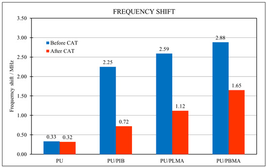
Figure 4.
Frequency shift results of the pristine PU and the PU–polymer composites before and after the CAT.
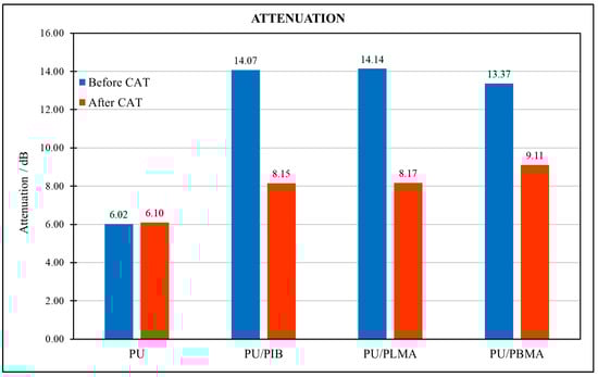
Figure 5.
Attenuation results of the pristine PU and the PU–polymer composites before and after the CAT.
The results of the attenuation and frequency shift for the coating with the pristine PU before and after the CAT confirmed that the PU is not affected by the test, as observed in the previous works [31], reinforcing its participation in the composite formation as described in the proposed mechanism. The results of the frequency shift, which is proportional to the mass deposited over the piezoelectric sensor element, for the PU–polymer composites indicate that, although a quantity of mass of the original deposition was removed by the CAT, a significant mass of the coating layer of the composites was preserved. The attenuation results are connected to the loss of energy by the propagation of the acoustic wave over the surface of the SAW sensor, providing an integral parameter related to the material uniformity and distribution over the active area of the sensor. The uniformity of the results of the attenuation for all the PU-composites after the CAT suggests that the remaining structures are similar in respect to their homogeneity, despite the difference in their structures due to the variation in the sensing polymers in their constitutions. This observation can be explained by the fact that the composition of PU-composites leads to the formation of coating layers with more structural similarity once all of them have PU as a common component in their structures. And the observed reduction and uniformity in the attenuation results after the CAT can be attributed in part to the mass reduction (as detailed in Figure 2) but also due to the improvement of the adhesion and material distribution, as observed before for the PU–polymer composites [31,34]. To explore more deeply the individual characteristics of the coating layers formed by each PU–polymer composite, microscopic analyses using SEM and DFM were performed.
The main object of the microscopy analysis was the central part of the active area of the piezoelectric sensor element, in the location with the intersection of three different regions of the element: the area with the gold electrodes fingers, the gold continuous contact pad, and the free quartz surface, in order to investigate the interaction of the coating materials with these constitutionally distinct regions of the piezoelectric sensor surface.
3.2. Uncoated SAW Sensor Element
Figure 6 presents the SEM images of an uncoated SAW sensor element ready for deposition, to provide a reference about how the clean surface should look.
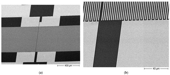
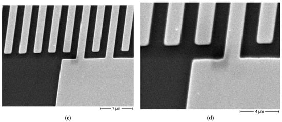
Figure 6.
SEM images of the surface of an uncoated piezoelectric sensor element at various magnifications. The active area of the piezoelectric sensor can be identified as the horizontal dark gray zone, which crosses the whole picture in the 100× magnification (a), 1000× magnification (b), 5000× magnification (c) and 10,000× magnification (d).
The observation of the locations presented in Figure 6c,d allows an inspection of the resulting interaction of the coating materials with the three kinds of constitutions of the surface of the sensor element to provide insights about the quality of the coverage by the coating material, its wettability to each surface, the obtained material distribution, the homogeneity of the layer, and the respective implications of these characteristics to the adhesion and mechanical stability of the resulting coating layer. From Figure 6 can be seen that all the regions of the surface of the uncoated SAW sensor element present very clean and unperturbed images by all the magnifications analyzed.
3.3. PU-PBMA Composite
The attenuation results indicated a homogeneous coating layer for the PU-PBMA composite (Figure 5) despite the high values of frequency shift obtained for the original deposition (before the CAT) for this coating material. The DFM images for the PU-PBMA original coating layer confirm the homogeneity of its deposition (Figure 7a). The SEM images also confirm the homogeneous aspect presented by the original coating layer of the PU-PBMA composite. By the magnifications of 5000× and 10,000× (Figure 8a,b) can be seen that the layer equally covered the quartz substrate as well as the gold fingers and electrodes in a homogeneous way.
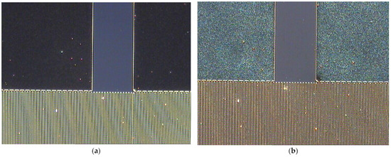
Figure 7.
(a) DFM images of the coating layer with the PU-PBMA composite before and (b) after the CAT. Magnification of 50×.
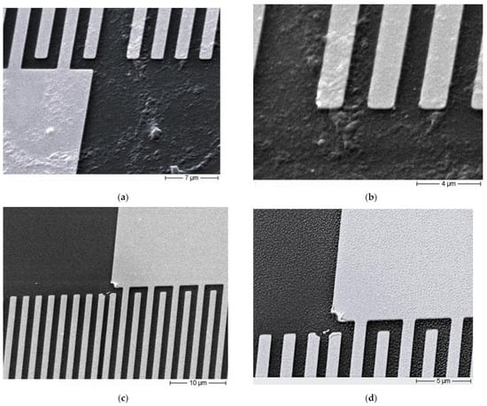
Figure 8.
SEM images of the PU-PBMA composites before and after the CAT. (a) Magnification of 5000×, before CAT; (b) 10,000×, before CAT; (c) 2500×, after CAT; (d) 5000×, after CAT.
After the application of the CAT, the DFM image reflects the modification of the structure of the coating layer (Figure 7b), indicating how the test affected the structure of the coating layer. Nevertheless, after the CAT the remaining coating layer still presents a regular aspect in terms of material distribution. This modification in the structure of the coating layer can be correlated to the frequency shift results (Figure 4), which indicates a loss of a significant amount of material by the PU-PBMA coating layer after the application of the CAT. The images of the SEM confirm the modification of the structure (Figure 8c,d), and the pattern observed in the SEM images agrees with that observed by the DFM images after the CAT.
As observed for the DFM, the SEM images show a homogeneous coverage over all the regions of the surface of the SAW element, with a very reproducible structure that should be the characteristic structure of the PU-PBMA composite that remains bound to the surface after the CAT.
3.4. PU-PLMA Composite
Figure 9 presents the images of DFM of the coating layer obtained with the PU-PLMA composite.
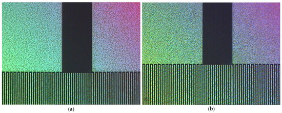
Figure 9.
DFM images of the coating layer with the PU-PLMA composite, (a) before and (b) after the CAT. Magnification of 50×.
The attenuation results indicated that the original coating layer with the PU-PLMA composite should present a homogenous deposition over the surface of the saw element (Figure 5). The homogeneity of the coverage with this composite is confirmed by the DFM image (Figure 9a), where a pattern can be observed for the coating with the PU-PLMA composite. The SEM images also indicate a very homogenous deposition of this coating material (Figure 10a,b), however, showing a quite different structure in comparison with the structure obtained with the PU-PBMA composite (Figure 7a and Figure 8a,b). The layer of the PU-PLMA composites appears to cover all regions of the surface, as also observed by the PU-PBMA composite.
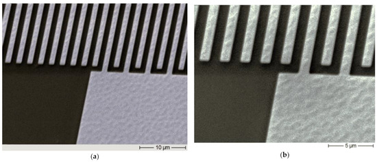
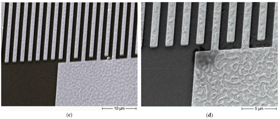
Figure 10.
SEM images of the deposition of the PU-PLMA composite as the sensing layer. (a) Magnification of 2500×, before CAT; (b) 5000×, before CAT; (c) 2500×, after CAT; (d) 5000×, after CAT.
The frequency shift results for the PU-PBMA composite (Figure 4) also indicated a significant loss of material occurred after the application of the CAT, but again resulting in a homogeneous coating layer after the CAT, according to the attenuation results. The DFM image after the CAT (Figure 9b) appears to confirm the ultrasonic results, where the layer appears to be cleaned after the CAT, indicating the removal of part of the material from the surface. However, the remaining layer presents homogeneity. The SEM results present more clearly the effect of the CAT, evidencing the fact that some part of the material was removed, while there is a very homogeneous and reproducible structure that remains after the CAT (Figure 10c,d). These results strongly suggest that the remaining structures after the CAT should correspond to the PU-PLMA composite formed by the coating process. The remaining structures of the two composite materials, PU-PBMA and PU-PLMA, are very distinct, evidencing the constitutional differences between the two coating materials.
3.5. PU-PIB Composite
The coating with the PU-PIB composite presented a different behavior for its deposition. The DFM images show a regular pattern that spreads itself over all regions of the surface of the SAW sensor element, apparently covering equally all the gold and the quartz regions of the surface (Figure 11a,b).
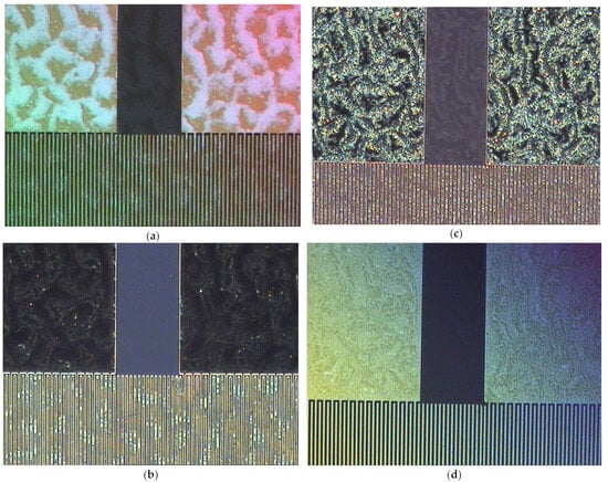
Figure 11.
DFM images of the coating with the PU-PIB composite as the coating material, (a,b) before CAT; (c,d) after the CAT. All images were made with a magnification of 50×.
The DFM images after the CAT indicated that the deposition had been modified, suggesting some loss of the original coating (Figure 11c,d), as was observed with the other PU–polymer composites. Again, the pattern observed by the deposition before the application of the CAT seems to be maintained but apparently being cleaned after the application of the CAT.
The SEM images confirm the observed with the DFM. The images before the CAT (Figure 12a,b) show a homogeneous coverage of all regions of the surface. From the SEM images can be seen that the coating material can be found over the gold pads, over the gold fingers of the interdigital structure, in between the gold fingers on the quartz trenches, and over the quartz regions, free of the gold electrode deposition.
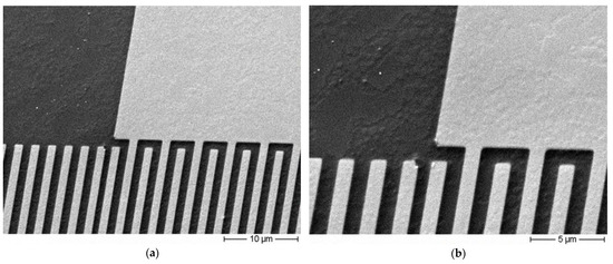
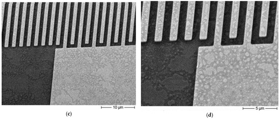
Figure 12.
SEM images of the deposition of the PU-PIB composite as the sensing layer. (a) 2500×, before CAT; (b) 5000×, before CAT; (c) 2500×, after CAT; (d) 5000×, after CAT.
After the CAT, the SEM images (Figure 12c,d) indicate that some material was removed from the original deposition, being the removal apparently occurring equally from all the regions of the surface of the SAW element. Once again, a remaining deposition with a particular structure is observed after the CAT, suggesting that the PU-PIB composite has also resisted the CAT, as observed for the other PU–polymer composites investigated. But, again, the structure of the remaining coating layer after the CAT is distinct from those observed for the other composites, possibly due to the differences in the chemical constitution of the composites.
As seen by the results, all the PU–polymer composites exhibited the same overall behavior with respect to their formation and reaction to the CAT, and all of them seem to follow the proposal mechanism explained in Figure 1 and Figure 2, independent of the sensing polymer combined with PU. The ultrasonic analyses are in perfect agreement with the microscopic observations for all the PU–polymer composites, revealing the role of each component in the formation of the composites. Despite the observation of the same overall behavior for all the PU–polymer composite analyzed so far, it is of crucial relevance to point out the achievements and advantages of this class of composite materials. As revealed by the microscopic analysis, each of the composites presented a characteristic microstructure and a pattern by its deposition over the complex surface of the piezoelectric sensor element, evidencing the individual influence of each polymer combined with PU. The microstructure of the coating layer will influence the selectivity against the analytes and the long-term stability of the coated sensor and, therefore, must be considered when these issues are addressed in future work. Although the composites presented different microstructures, they all resulted in highly uniform coating layers, showing great chemical resistance and adhesion improvements. And the most important feature of the PU–polymer composites is the achievement of all the improvements observed independently of the nature of the polymer used, keeping in mind that it is the polymer combined with PU that will be responsible for the quality of the sensor response in the detection process by the sensor system.
4. Conclusions
The ultrasonic results explained the behavior of the composites with respect to the CAT and could be correlated with the microscopy results, revealing that all the composites provided homogeneous coating layers before and after the CAT, also indicating the extension of the removal of the material from the surface by the CAT for each composite. The ultrasonic results agreed with the proposed mechanism of formation of the PU–polymer composites and are in perfect agreement with the microscopy results, reinforcing the function of each component of the composites in the properties of the obtained coating layer, where PU should act as a binder to form the polymeric composite with the sensing polymer used and, at same time, as an adhesion promoter, without interfering in the sensor response, which depends only on the characteristics of the sensing polymer forming the composite. Although seeming to follow the same mechanism of formation, the microstructures of each composite are distinct, reflecting the characteristics of the sensing polymer used in the composite. The microscopy results provided a relevant visualization of the structure and interaction of the composites with the different regions of the complex surface of the piezoelectric sensor element, allowing the evaluation of the macroscopic material distribution and the uniformity of the coating deposition. The microscopy methods could successfully detect the effects of the CAT in the coating layer of each PU–polymer composite, revealing the preserved structures that resisted the CAT, providing relevant information about the adhesion of the coating materials to the surface of the sensor that plays an important role in the long-term behavior of the SAW sensors in real applications. It was observed that the nature of the sensing polymer used strongly affects the properties of the composites in terms of their structure and their interaction with the surface of the sensor element. The results of the CAT showed that all the coating layers of the PU–polymer composites presented chemical and mechanical stability, indicating that this new class of coating materials based on the PU–polymer composites provided coating layers with improved structural properties, maintaining the chemical affinity and sensitivity of the sensing polymer used. In further work, the formation of the composite as a function of the PU–polymer stoichiometry will be investigated as well as the influence of composition of the polyurethane polymer used in the composites.
The results of this study considerably expand the choice of chemical environments for chemical sensitization since any type of polymer can virtually be used as a coating material for SAW technology. This makes this type of polymeric composite promising for other sensor technologies, like optical and biosensors, where the sensitization requires rich chemistry properties in terms of interactions, along with enhanced adhesion and other specific mechanical properties that can potentially be achieved by a tailor-made PU–polymeric composite, opening a vast and broad spectrum of possibilities in terms of chemical sensitization.
Author Contributions
Conceptualization, M.d.S.d.C.; Methodology, M.R. and A.V.; Software, A.V.; Validation, M.D. and U.G.; Formal analysis, M.d.S.d.C., M.D. and U.G.; Investigation, M.d.S.d.C.; Data curation, M.D. and U.G.; Writing—original draft, M.d.S.d.C.; Writing—review & editing, M.d.S.d.C. and M.R.; Supervision, M.R.; Project administration, M.R. All authors have read and agreed to the published version of the manuscript.
Funding
The publication was funded by the Open Access Publication Fund of the Karlsruhe Institute of Technology.
Informed Consent Statement
Not applicable.
Data Availability Statement
Data are contained within the article.
Conflicts of Interest
The authors declare no conflicts of interest.
References
- Yang, Y.; Dejous, C.; Hallil, H. Trends and Applications of Surface and Bulk Acoustic Wave Devices: A Review. Micromachines 2023, 14, 43. [Google Scholar] [CrossRef] [PubMed]
- Mandal, D.; Banerjee, S. Surface Acoustic Wave (SAW) Sensors: Physics, Materials, and Applications. Sensors 2022, 22, 820. [Google Scholar] [CrossRef] [PubMed]
- Länge, K. Bulk and Surface Acoustic Wave Sensor Arrays for Multi-Analyte Detection: A Review. Sensors 2019, 19, 5382. [Google Scholar] [CrossRef] [PubMed]
- Yunas, J.; Mulyanti, B.; Hamidah, I.; Said, M.M.; Pawinanto, R.E.; Ali, W.A.F.W.; Subandi, A.; Hamzah, A.A.; Latif, R.; Majlis, B.Y. Polymer-Based MEMS Electromagnetic Actuator for Biomedical Application: A Review. Polymers 2020, 12, 1184. [Google Scholar] [CrossRef]
- Misra, A.; Shahiwala, A. (Eds.) Applications of Polymers in Drug Delivery, 2nd ed.; Elsevier: Amsterdam, The Netherlands, 2020. [Google Scholar]
- Nghiem, T.-L.; Coban, D.; Tjaberings, S.; Gröschel, A.H. Recent Advances in the Synthesis and Application of Polymer Compartments for Catalysis. Polymers 2020, 12, 2190. [Google Scholar] [CrossRef]
- Sun, Q.; Dai, Z.; Meng, X.; Xiao, F.-S. Porous polymer catalysts with hierarchical structures. Chem. Soc. Rev. 2015, 44, 6018–6034. [Google Scholar] [CrossRef]
- Cichosz, S.; Masek, A.; Zaborski, M. Polymer-based sensors: A review. Polym. Test. 2018, 67, 342–348. [Google Scholar] [CrossRef]
- Di Pietrantonio, F.; Benetti, M.; Cannatà, D.; Verona, E.; Palla-Papavlu, A.; Dinca, V.; Dinescu, M.; Mattle, T.; Lippert, T. Volatile toxic compound detection by surface acoustic wave sensor array coated with chemoselective polymers deposited by laser induced forward transfer: Application to sarin. Sens. Actuators B Chem. 2012, 174, 158–167. [Google Scholar] [CrossRef]
- Sayago, I.; Fernández, M.; Fontecha, J.; Horrillo, M.; Vera, C.; Obieta, I.; Bustero, I. New sensitive layers for surface acoustic wave gas sensors based on polymer and carbon nanotube composites. Sens. Actuators B Chem. 2012, 175, 67–72. [Google Scholar] [CrossRef]
- Yadava, R.; Kshetrimayum, R.; Khaneja, M. Multifrequency characterization of viscoelastic polymers and vapor sensing based on SAW oscillators. Ultrasonics 2009, 49, 638–645. [Google Scholar] [CrossRef]
- Zhang, D.; Tong, J.; Xia, B. Humidity-sensing properties of chemically reduced graphene oxide/polymer nanocomposite film sensor based on layer-by-layer nano self-assembly. Sens. Actuators B Chem. 2014, 197, 66–72. [Google Scholar] [CrossRef]
- Tai, H.; Zhen, Y.; Liu, C.; Ye, Z.; Xie, G.; Du, X.; Jiang, Y. Facile development of high performance QCM humidity sensor based on protonated polyethylenimine-graphene oxide nanocomposite thin film. Sens. Actuators B Chem. 2016, 230, 501–509. [Google Scholar] [CrossRef]
- Hung, T.-T.; Chung, M.-H.; Chiu, J.-J.; Yang, M.-W.; Tien, T.-N.; Shen, C.-Y. Poly(4-styrenesulfonic acid) doped polypyrrole/tungsten oxide/reduced graphene oxide nanocomposite films based surface acoustic wave sensors for NO sensing behavior. Org. Electron. 2020, 88, 106006. [Google Scholar] [CrossRef]
- Wang, B.; Zhou, L.; Wang, X. Surface acoustic wave sensor for formaldehyde gas detection using the multi-source spray-deposited graphene/PMMA composite film. Front. Mater. 2023, 9, 1025903. [Google Scholar] [CrossRef]
- Viespe, C.; Miu, D. Characteristics of Surface Acoustic Wave Sensors with Nanoparticles Embedded in Polymer Sensitive Layers for VOC Detection. Sensors 2018, 18, 2401. [Google Scholar] [CrossRef] [PubMed]
- Gu, Y.; Zhao, J.; Johnson, J.A. A (Macro)Molecular-Level Understanding of Polymer Network Topology. Trends Chem. 2019, 1, 318–334. [Google Scholar] [CrossRef]
- Tang, K.-T.; Li, C.-H.; Chiu, S.-W. An Electronic-Nose Sensor Node Based on a Polymer-Coated Surface Acoustic Wave Array for Wireless Sensor Network Applications. Sensors 2011, 11, 4609–4621. [Google Scholar] [CrossRef]
- Su, Y.-F.; Han, G.; Kong, Z.; Nantung, T.; Lu, N. Embeddable Piezoelectric Sensors for Strength Gain Monitoring of Cementitious Materials: The Influence of Coating Materials. Eng. Sci. 2020, 11, 66–75. [Google Scholar] [CrossRef]
- Lowdon, J.W.; Diliën, H.; Singla, P.; Peeters, M.; Cleij, T.J.; van Grinsven, B.; Eersels, K. MIPs for commercial application in low-cost sensors and assays—An overview of the current status quo. Sens. Actuators B Chem. 2020, 325, 128973. [Google Scholar] [CrossRef]
- Navale, S.; Mane, A.; Chougule, M.; Sakhare, R.; Nalage, S.; Patil, V. Highly selective and sensitive room temperature NO2 gas sensor based on polypyrrole thin films. Synth. Met. 2014, 189, 94–99. [Google Scholar] [CrossRef]
- Hu, J.; Qu, H.; Chang, Y.; Pang, W.; Zhang, Q.; Liu, J.; Duan, X. Miniaturized polymer coated film bulk acoustic wave resonator sensor array for quantitative gas chromatographic analysis. Sens. Actuators B Chem. 2018, 274, 419–426. [Google Scholar] [CrossRef]
- Palla-Papavlu, A.; Voicu, S.I.; Dinescu, M. Sensitive Materials and Coating Technologies for Surface Acoustic Wave Sensors. Chemosensors 2021, 9, 105. [Google Scholar] [CrossRef]
- Jasek, K.; Pasternak, M.; Grabka, M.; Neffe, S.; Zasada, D. Deposition of Polymer Sensor Films on SAW Surface by Electrospraying Technology. Arch. Acoust. 2017, 42, 507–513. [Google Scholar] [CrossRef][Green Version]
- Verma, P.; Yadava, R.D.S. Polymer selection for SAW sensor array based electronic noses by fuzzy c-means clustering of partition coefficients: Model studies on detection of freshness and spoilage of milk and fish. Sens. Actuators B Chem. 2015, 209, 751–769. [Google Scholar] [CrossRef]
- Matatagui, D.; Martí, J.; Fernández, M.; Fontecha, J.; Gutiérrez, J.; Gràcia, I.; Cané, C.; Horrillo, M. Chemical warfare agents simulants detection with an optimized SAW sensor array. Sens. Actuators B Chem. 2011, 154, 199–205. [Google Scholar] [CrossRef]
- Grate, J.W.; McGill, R.A. Dewetting Effects on Polymer-Coated Surface Acoustic Wave Vapor Sensors. Anal. Chem. 1995, 67, 4015–4019. [Google Scholar] [CrossRef]
- Stewart, K.M.E.; Penlidis, A. Designing polymeric sensing materials: What are we doing wrong? Polym. Adv. Technol. 2016, 28, 319–344. [Google Scholar] [CrossRef]
- Brassat, K.; Lindner, J.K.N. Nanoscale Block Copolymer Self-Assembly and Microscale Polymer Film Dewetting: Progress in Understanding the Role of Interfacial Energies in the Formation of Hierarchical Nanostructures. Adv. Mater. Interfaces 2020, 7, 1901565. [Google Scholar] [CrossRef]
- Rapp, M.; Voigt, A.; Dirschka, M.; Carvalho, M.d.S.d. The Use of Polyurethane Composites with Sensing Polymers as New Coating Materials for Surface Acoustic Wave-Based Chemical Sensors—Part I: Analysis of the Coating Results, Sensing Responses and Adhesion of the Coating Layers of Polyurethane–Polybutylmethacrylate Composites. Coatings 2023, 13, 1911. [Google Scholar] [CrossRef]
- Carvalho, M.d.S.d.; Rapp, M.; Voigt, A.; Dirschka, M. The Use of Polyurethane Composites with Sensing Polymers as New Coating Materials for Surface Acoustic Wave-Based Chemical Sensors—Part II: Polyurethane Composites with Polylaurylmetacrylate, Polyisobutene, and Poly(chlorotrifluoroethylene-co-vinylidene Fluoride): Coating Results, Relative Sensor Responses and Adhesion Analysis. Coatings 2024, 14, 778. [Google Scholar] [CrossRef]
- Gao, P.F.; Lei, G.; Huang, C.Z. Dark-Field Microscopy: Recent Advances in Accurate Analysis and Emerging Applications. Anal. Chem. 2021, 93, 4707–4726. [Google Scholar] [CrossRef] [PubMed]
- La Spina, R.; António, D.C.; Desmet, C.; Valsesia, A.; Bombera, R.; Norlén, H.; Lettieri, T.; Colpo, P. Dark Field Microscopy-Based Biosensors for the Detection of E. coli in Environmental Water Samples. Sensors 2019, 19, 4652. [Google Scholar] [CrossRef] [PubMed]
- Carvalho, M.d.S.d.; Rapp, M.; Voigt, A.; Dirschka, M. The Use of Polyurethane Composites with Sensing Polymers as New Coating Materials for Surface Acoustic Wave-Based Chemical Sensors—Part III: Ultrasonic Analyses and Optical Microscopy Characterization of the Coating Results. Coatings 2024, 14, 846. [Google Scholar] [CrossRef]
Disclaimer/Publisher’s Note: The statements, opinions and data contained in all publications are solely those of the individual author(s) and contributor(s) and not of MDPI and/or the editor(s). MDPI and/or the editor(s) disclaim responsibility for any injury to people or property resulting from any ideas, methods, instructions or products referred to in the content. |
© 2025 by the authors. Licensee MDPI, Basel, Switzerland. This article is an open access article distributed under the terms and conditions of the Creative Commons Attribution (CC BY) license (https://creativecommons.org/licenses/by/4.0/).