Review

Recent Progress in Dielectric/Ag/Dielectric Transparent Electrodes on Flexible Substrates

1
Department of Vacuum and Process Equipment, Hefei University of Technology, Hefei 230009, China
2
School of Automotive and Transportation Engineering, Hefei University of Technology, Hefei 230009, China
3
Intelligent Manufacturing Institute, Hefei University of Technology, Hefei 230051, China
*
Authors to whom correspondence should be addressed.
Coatings 2025, 15(12), 1370; https://doi.org/10.3390/coatings15121370 (registering DOI)
Submission received: 9 October 2025 / Revised: 26 October 2025 / Accepted: 30 October 2025 / Published: 24 November 2025
(This article belongs to the Section Thin Films)

Abstract

Dielectric/Ag/dielectric (DAD) multilayer thin-film transparent electrode features high visible-light transmittance, low sheet resistance, good mechanical flexibility, and low haze. The fabrication techniques are compatible with large-scale integrated circuits, and the materials are cheap. These advantages make the DAD transparent electrodes a promising alternative to indium tin oxide (ITO) electrodes for flexible devices. This review summarizes recent advances in DAD transparent electrodes on flexible substrates, mainly focusing on the opto-electrical performance improvement due to damping of the localized surface resonance (LSPR) of Ag nanoparticles (AgNPs). It begins with an analysis of the performance-limiting factors of DAD transparent electrodes, elucidating the importance of damping the LSPR of AgNPs. Subsequently, the state-of-the-art fabrication methods for Ag ultrathin films of weak LSPR and the dielectric material optimization are reviewed. It concludes with perspectives on future research.

1. Introduction

Flexible transparent electrode (FTE) is one of the essential components of flexible optoelectronic devices such as flexible displays, solar cells, and wearable electronic devices [1,2,3]. The most commonly used transparent electrode is indium oxide tin-doped (ITO) thin film. The ITO transparent electrode is of high visible-light transmittance, low resistivity, and good corrosion resistance, but poor flexibility and low storage of indium in the earth make it unsuitable for flexible optoelectronic devices. To overcome these limitations, several alternative FTEs [4], such as graphene [5], carbon nanotubes [6], conductive polymers [7], metal nanowires, metal nano grids [8,9], and dielectric/metal/dielectric multilayer thin film (DMD), have been developed [10]. Among them, the DMD transparent electrode, a layer of metal sandwiched by two dielectric layers s, using the metal layer to improve the flexibility and electrical conductivity, exhibits high electrical conductivity, excellent mechanical flexibility, high visible-light transmittance, and good environmental stability. Furthermore, the DMD transparent electrode can be prepared by vacuum coating, which is compatible with the manufacturing process of ultra-large-scale integrated circuits and thus suitable for mass production [11,12]. Also, the work function of the DMD transparent electrodes can be controlled via dielectric selection, allowing them to be used as a cathode–anode or even as an intermediate electrode in tandem solar cells [13]. Last but not least, the component materials of DMD are cheaper than ITO and most other flexible transparent electrodes. These advantages make the DMD transparent electrodes the most promising alternative to ITO electrodes used in flexible devices, and, therefore, they have received widespread attention in recent years [2,4,11,12,13,14,15,16,17,18,19,20].
The metal layer of DMD transparent electrodes determines the electrical–optical properties and the mechanical flexibility of the electrodes. Its thickness should be large enough to ensure the conductivity of the layer and, at the same time, be as small as possible so as not to impede the required transparency. Typically, highly ductile and conductive metals such as Au, Ag, Al, and Cu are employed, with Ag being the most prevalent choice [11,14,16,17,19] due to its superior electrical conductivity, center color [17], and stability (Ag-based DMD denoted as DAD). However, the Ag layer not only reflects but also absorbs incident light when the thickness of the Ag layer is smaller than 10 nm, resulting in low transmittance of DAD. When the refractive indices and thicknesses of the dielectric layers and the Ag layer match each other, the reflected light from each interface between the dielectric layer and the Ag layer undergoes coherent cancellation, such that the reflection can be minimized. However, the transmittance of the DAD electrode is still low and severely limits its applications.
Since 2008, Jeong et al. [11], for the first time, prepared Al2O3/Ag/Al2O3 flexible transparent electrodes on polyethylene terephthalate (PET) substrates using magnetron sputtering and vacuum evaporation deposition techniques; great progress has been made to enhance the optical transmittance of DAD. Many good reviews have been presented. However, the low transmittance is in fact caused by large absorbance induced by the localized surface plasmon resonance (LSPR) of silver nanoparticles (AgNPs), of which the Ag layer is composed when the thickness of the Ag layer is smaller than 10 nm. Herein, we review the recent advances of the DAD transparent electrode from the Ag layer and the dielectric layer [9,10,11,12,13,14,15,16,17,18,19], mainly focusing on the recent advances in the optic–electric performance improvement from the point of view of damping the LSPR of AgNPs. The detailed principle of LSPR is discussed in Section 2.

2. Research Progress of the Ag Layer

2.1. Analysis of the Limitation Factors for the Optical–Electric Performance of DAD Transparent Electrodes
As mentioned above, coherent cancellation can minimize optical loss caused by the reflection from the DAD, but the transmittance of the DAD is still not as high as expected. It is wavelength-related, and the maximal intensity is around wavelength of 550 nm with an average transmittance (Tav) smaller than 85%. This low transmittance is, in fact, caused by the absorbance, not the scattering of the Ag layer.
The surface energy of Ag thin film is about 1.2–1.4 J/cm2 [21], which is much larger than that of dielectric materials, which are normally smaller than 1.0 J/cm2 [22]; therefore, Ag thin film grown on dielectric layers follows Volmer–Weber (island) growth mode [23]. Firstly, the atoms reaching the substrate form nuclei on the surface. Then, the subsequently arrived Ag atoms join the existing nuclei and promote the nuclei to grow into islands (nanoparticles), as shown in Figure 1a. When the nanoparticles connect to each other, a continuous conductive thin film is formed. The minimum average thickness that forms a conductive thin film is defined as the percolation threshold. Here, we refer to it as conductive critical thickness (tCT). tCT depends on the nucleation density. The greater the nucleation density is, the smaller the mean size of the AgNPs is, and thus the smaller the tCT is.
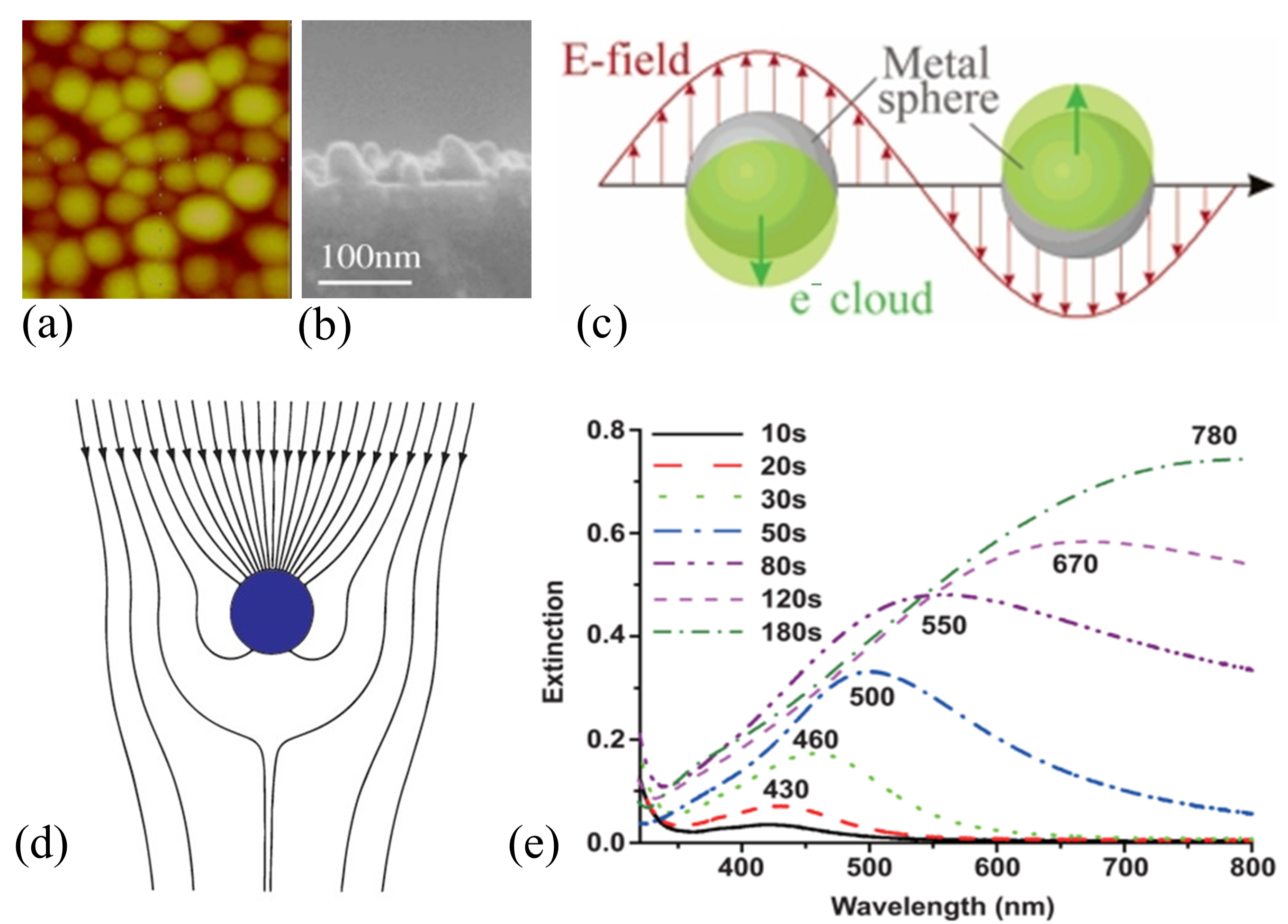
The nucleation density depends on the materials of thin films and substrates, and the surface physical and chemical environment of the substrate [23]. When Ag thin film is deposited on clean glass substrates using vacuum evaporation techniques, tCT is about 10 nm [24,25,26]. The mean size of AgNPs is smaller than 50 nm, as shown in Figure 1b [27]. AgNPs in this size range possess strong LSPR [28]. LSPR refers to the resonance of the free electrons contained in the AgNPs with the incident electric field (Figure 1c) [29]. As a result, the AgNPs strongly absorb the incident light (Figure 1d) [30]. The LSPR peaks of isolated AgNPs are around 340 nm, but mutual coupling of adjacent nanoparticles broadens this resonance wavelength to the entire visible light range (Figure 1e) [31]. Therefore, although the absorbance of the Ag layer is small on a macroscopic scale, it is tremendously large on a nanoscale due to the LSPR of AgNPs. This strong absorbance sharply reduces the transmittance of the DAD transparent electrodes.
Figure 1. The introduction of LSPR. (a) The AFM image of AgNPs [28]. (b) The FESEM image of AgNPson Si substrate [27]. (c) The principal sketch of LSPR [29]. (d) Sketch showing the strong absorbance of metal nanoparticles caused by LSPR [30]. (e) The LSPR spectrum tuned by changing the deposition time of silver [31].
Coatings 15 01370 g001
The mean size of AgNPs is smaller than 50 nm when the thickness of the Ag layer in DAD is near tCT [24,29]. According to the calculation provided by ref. [32], the scattering from AgNPs is much weaker than the LSPR absorbance. For example, the scattering is less than 10% of the absorbance when the AgNPs’ size is smaller than 50 nm. Therefore, it is the LSPR absorbance, not the scattering, that is responsible for the low transmittance of the DAD transparent electrode [33].
The LSPR of AgNPs can be weakened through (1) reducing the AgNPs’ size and (2) suppressing the AgNPs’ agglomeration [30,33,34]. Low agglomeration means that the nanoparticles are flatter and cover a larger area than high agglomeration, as shown in Figure 2. This means that the wettability is high [35]. It is obvious that reducing the AgNPs’ size and suppressing the AgNPs’ agglomeration make the Ag layer dense and smooth; therefore, the tCT and the surface roughness are reduced.
On the other hand, many papers attributed the low transmittance of DAD to the scattering caused by the surface roughness and to the large tCT of DAD. The main methods to reduce the surface roughness and the tCT are reducing the AgNPs’ size and suppressing the AgNPs’ agglomeration [36,37]. However, scattering is less than 10% of the absorbance in the interesting size range [32]; therefore, those methods developed to reduce scattering are, in fact, playing roles by damping the LSPR to reduce absorbance.
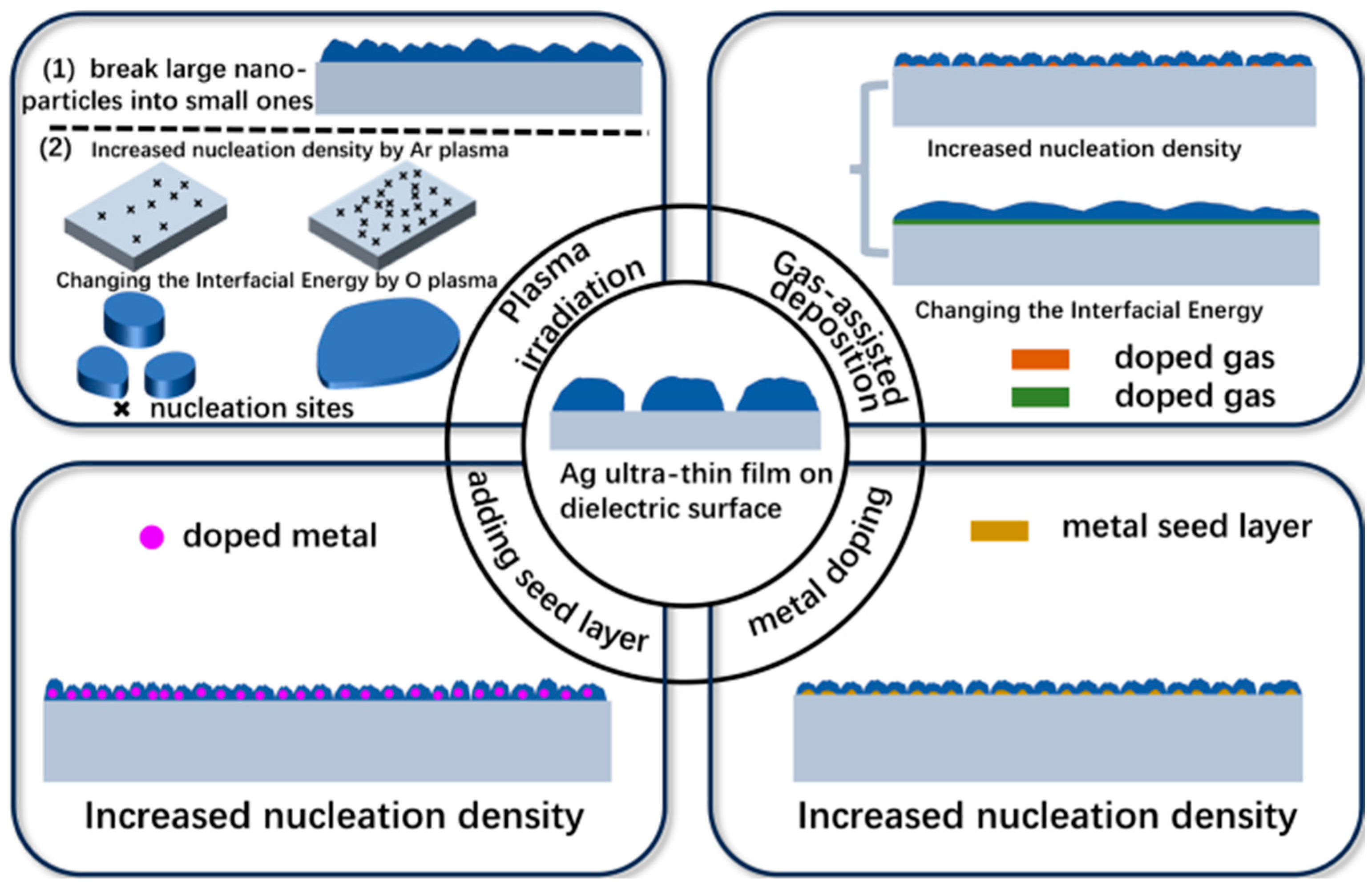
At present, nanoparticle size reduction can be achieved via directly breaking down large nanoparticles into small ones through Ar plasma irradiation [27] or by increasing the nucleation density in the early stage of silver thin-film growth [23]. The main techniques to increase the nucleation density and thus reduce the size of AgNPs include (1) introducing impurities such as doping [38], (2) introducing defects on the substrate surface in the initial stage of the Ag thin-film growth by Ar plasma irradiation [39,40], or by pre-depositing seed layers [41,42]. Suppressing nanoparticle agglomeration is mainly realized by increasing the surface energy of the substrate or reducing the interface energy of the Ag layer and the substrates [43] by gas-assisted deposition [44] or by active plasma irradiation [39]. A complex schematic diagram conceived to express the mechanisms is shown in Figure 3. The progress of the opto-electrical performance of DAD transparent electrodes based on these techniques is reviewed in detail in the following sections. They are plasma irradiation, gas-assisted deposition, metal doping, and pre-deposited seed layers.

2.2. Plasma Irradiation

Plasma irradiation refers to optimizing the DAD performance by inert Ar or active oxygen plasma via modifying the surface morphology of the Ag layer or the physical and chemical state of the Ag layer and the bottom dielectric layer of DAD electrodes. Through the irradiation of the Ag layer by Ar plasma [29], large AgNPs can be broken into small ones to reduce the nanoparticles’ size and thus increase the density of the Ag layer. Irradiation of the surface of the bottom dielectric layer by Ar plasma can produce defects to increase the nucleation density of the AgNPs. Irradiation by oxygen plasma can change the surface energy to prevent the agglomeration of AgNPs [39,43].
In 2015, our group, using Ar plasma irradiation of the Ag layer of the TiO2/Ag/TiO2 electrode, initiated the study of improving the optoelectronic performance of DAD electrodes by plasma produced by RF glow discharge for the first time [27]. As shown in Figure 4, after 10 s irradiation by Ar plasma, the Tav of DAD electrodes in the visible range reached 94%, with the sheet resistance (Rs) as low as 6 Ω/sq and the figure of merit (FOM = T 10 R s , [45]) value reaching 112 × 10−3 Ω−1.
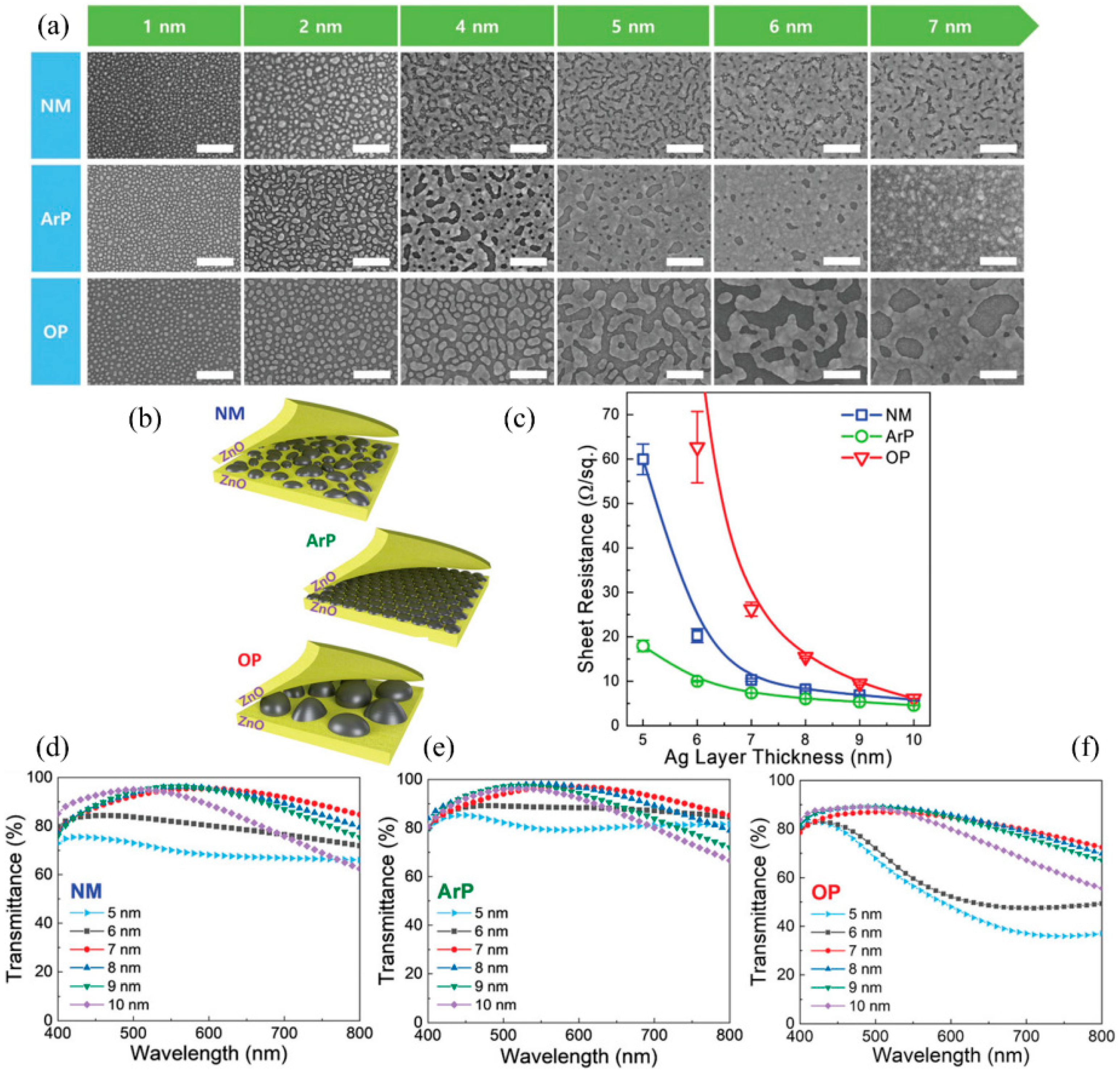
Following our study, in 2021, Lee et al. [39] applied argon and oxygen plasma to the bottom ZnO layer of ZnO/Ag/ZnO transparent electrodes to regulate the opto-electrical performance. Ultrathin continuous Ag nanofilm with a threshold thickness less than 7.0 nm was prepared. The Tav of the ZnO/7.0 nm Ag/ZnO flexible transparent electrode on PI substrate reaches 92.3% in the visible light range, with a Rs of 7.14 Ω/sq and a FOM value of 62.85 × 10⁻³ Ω−1. Figure 5a compares the effects of ArP (RF 30 W, 2.6 Pa for 10 min) and OP (RF 50 W, 2.6 Pa for 10 min) on modulating the surface morphologies of the Ag layer. As shown in the sketch in Figure 5b, the sizes of AgNPs on the unmodified and the OP-irradiated ZnO surface are larger than those on the ArP-irradiated surface. By employing combined molecular dynamics (MD)/force-bias Monte Carlo (fbMC) simulations, the authors suggested that a large number of oxygen vacancies were formed on the ZnO surface that was irradiated by ArP. Ag atoms reaching the surface were adsorbed on the oxygen vacancies and bounded to the internal Zn atoms, which greatly impeded the diffusion of silver atoms and increased the nucleation density. Since the size of the AgNPs was reduced, the threshold thickness was reduced (Figure 5c), and at the same time, the LSPR was weakened, resulting in higher transmittance of the sample modified by ArP (Figure 5d–f).
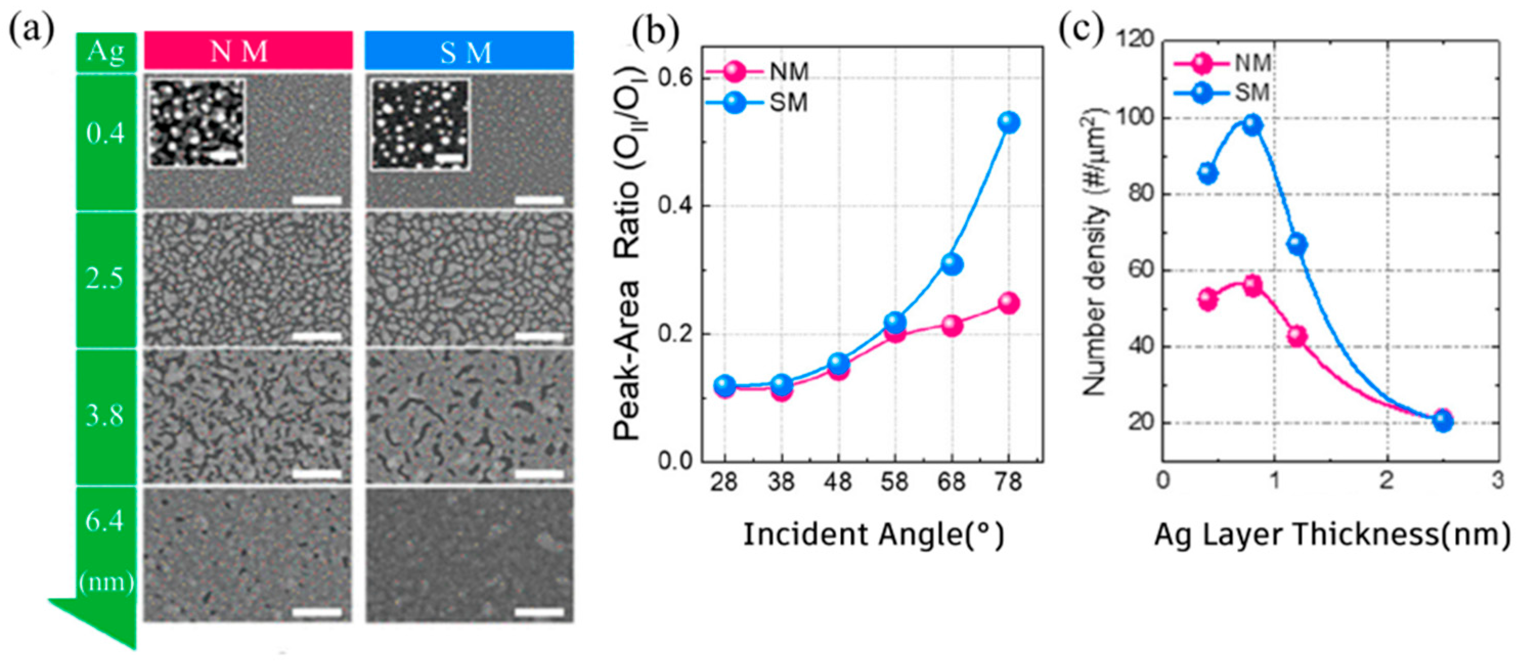
In 2022, Choi et al. [40] irradiated the surfaces of amorphous TiOx with Ar plasma (unirradiated is NM-TiOx and irradiated is SM-TiOx). Small surface roughness and tCT smaller than 6.4 nm were achieved (Figure 6a). Significant improvement of the wettability of the Ag thin film simultaneously increased both the electric conductivity and the visible-light transmittance of the TiOx/Ag/ZnO (TAZ) on the PET substrate. Angle-resolved X-ray photoelectron spectroscopy (ARXPS) analysis revealed that the surface of SM-TiOx had a large number of oxygen vacancies (OII, Figure 6b), providing nucleation sites and increasing the nucleation density (Figure 6c). The Tav of the TiOx/6.4 nm Ag/ZnO (TAZ) transparent electrode in the visible light range reached 96.5%. The Rs was as low as 6.0 Ω/sq and the FOM value was as high as 116.7 × 10⁻³ Ω−1.
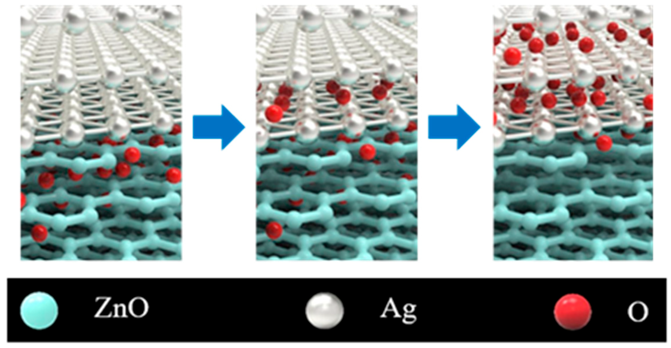
The irradiation process and its parameters play an important role. For instance, OP could not enhance nucleation density, as shown in Figure 5 [40], while it could have acted in this way in a different condition. In 2021, Jeong et al. [43] discovered that irradiation of the bottom ZnO layer using OP could also improve the wettability of the Ag thin film. The mechanism is shown in Figure 7. Driven by thermodynamics, excessive O atoms were doped into the lattice near the ZnO surface. These O atoms migrated from the ZnO lattice to the Ag thin film. Some were doped into the Ag lattice, increasing the nucleation sites and thus reducing the nanoparticle size; some were combined with Ag atoms to form Ag2O, reducing the interfacial energy between the Ag layer and ZnO layer and thus preventing the agglomeration of the AgNPs.
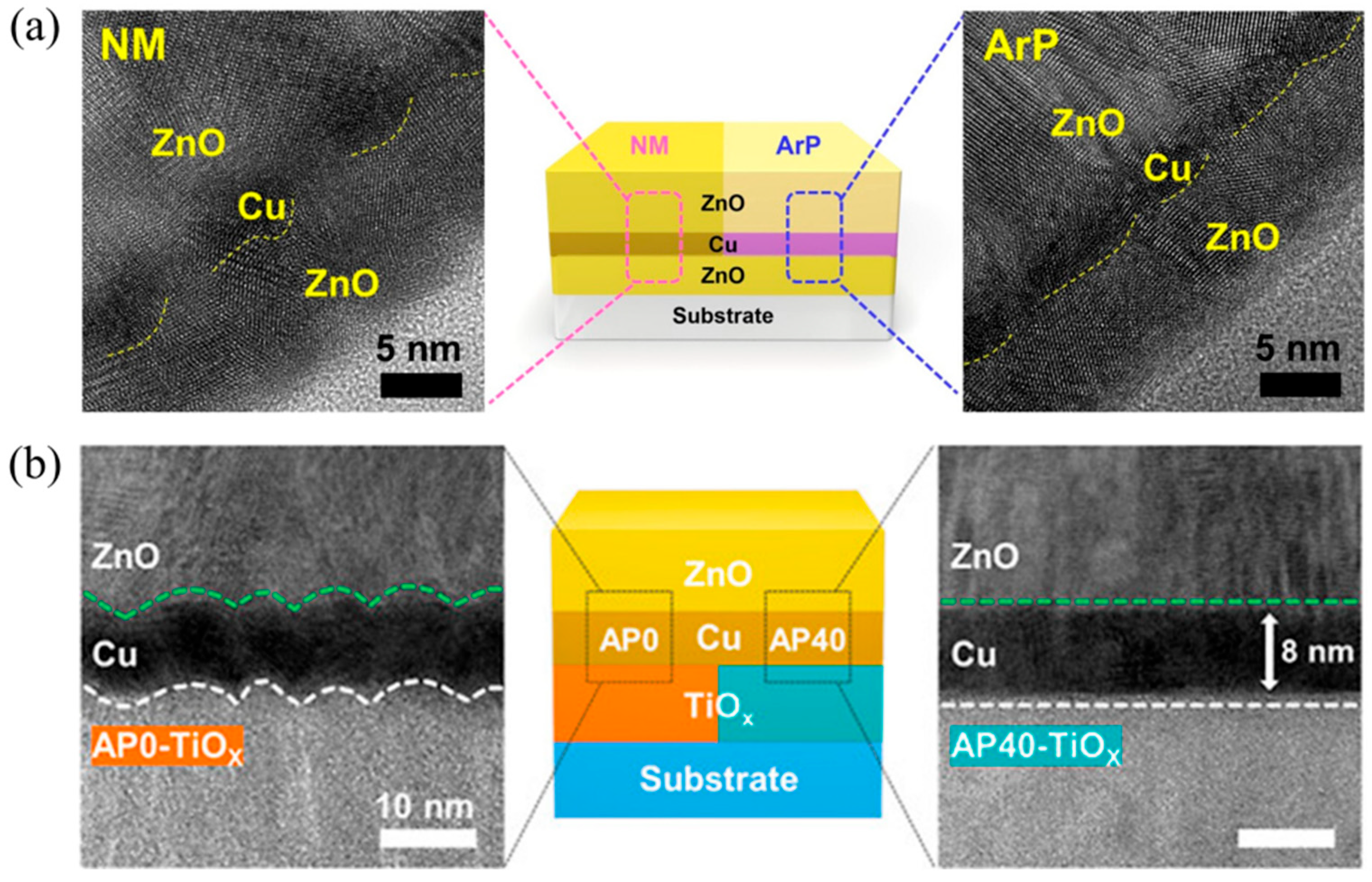
In 2023, Vo et al. [46] fabricated ZnO/5 nm Cu/ZnO transparent electrodes. By irradiation of the bottom ZnO using ArP (RF discharge for 2 min, Ar 20 sccm), it was found that the irregularity at the interface of ZnO/Cu was significantly reduced, as shown in Figure 8a (The yellow dashed line marks the interface between ZnO layer and Cu layer). The resultant FOM was 63 × 10−3 Ω−1, which is 53% greater than that of the unaltered, otherwise identical, structure. In 2024, Lim et al. [47] irradiated the bottom TiO2 layer of the TiO2/Cu/ZnO transparent electrode using Ar plasma (RF 20 W, Ar 20 sccm, 2.7 Pa for 40 min, AP40-TiOx). The surface roughness of the TiOx layer was gradually reduced from 0.69 to 0.35 nm, and the surface roughness of the Cu layer was reduced, forming ultra-smooth TiOx/Cu and Cu/ZnO interfaces (Figure 8b). A FOM value as high as 113 × 10−3 Ω−1 was achieved, which is about 200% higher than that of the unmodified structure. These findings about ArP on the bottom dielectric layer of dielectric/Cu/dielectric transparent electrode can help us to better understand the opto-electrical performance improvement of DAD induced by ArP.
According to the above studies, plasma irradiation is very efficient in improving the optoelectronic performance of DAD. The FOM values can be higher than 100 × 10−3 Ω−1.

2.3. Gas-Assisted Deposition

Gas-assisted deposition technology refers to introducing a trace amount of O2 [48,49,50,51,52,53,54,55] or N2 [44,56,57] in the early stage or during the whole process of Ag thin-film growth. On the one hand, the incorporated O and N atoms diffuse into the Ag lattice and produce additional nucleation sites; on the other hand, an AgOx interfacial layer is formed, which reduces the surface energy difference between the Ag thin film and the dielectric surface. The former reduces the AgNPs’ size, and the latter suppresses the AgNPs’ agglomeration. In addition, oxygen in the Ag lattice can increase the refractive index of the Ag and thus can suppress the reflection of incident light. These combined effects simultaneously weaken the LSPR and lower the tCT.
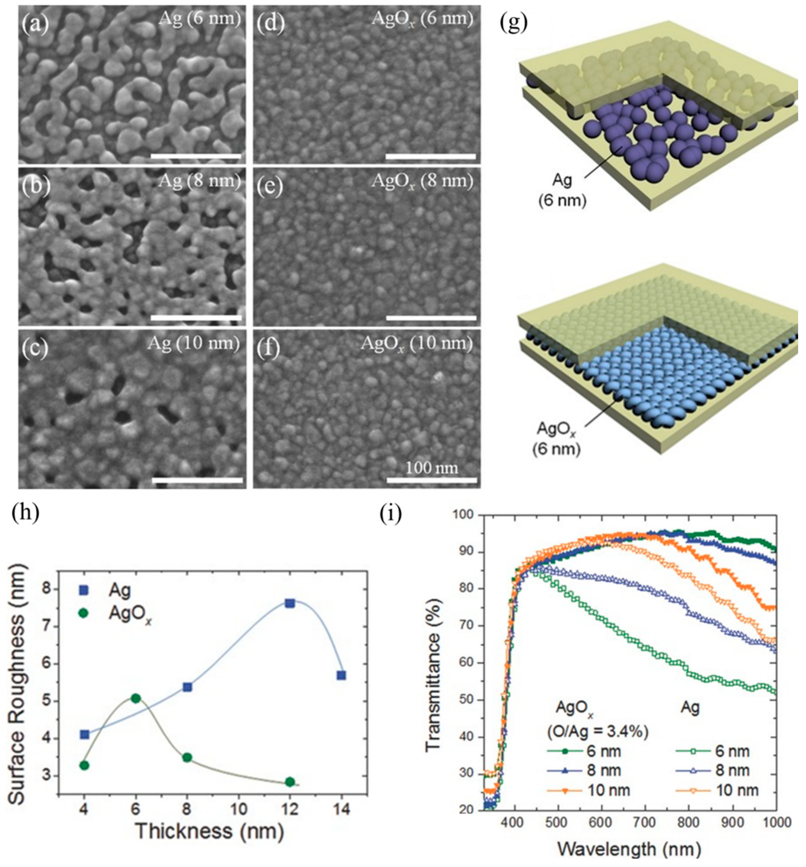
In 2014, Wang et al. [48], for the first time, prepared ZnO/AgOx/ZnO flexible transparent electrodes on PET substrates by introducing a small amount of oxygen (O/Ag = 3.4 at%) during the vacuum sputtering deposition of Ag thin films. The Ag thin film was transformed from a three-dimensional granular state to a two-dimensional AgOx thin film (Figure 9a–g) with a tCT smaller than 6 nm. In addition, the surface roughness of the 8 nm Ag thin film decreased from 5.3 nm to 3.5 nm (Figure 9h). The Tav of the ZnO/8 nm AgOx/ZnO transparent electrode in the visible light range reached 91% (Figure 9i), with a Rs of 20 Ω/sq, resulting in a FOM value of 19.47 × 10⁻³ Ω−1. In 2016, Zhang et al. [49] improved the continuity of the Ag thin film by introducing oxygen of 2%–3% O2/(Ar + O2) during vacuum sputtering. The fabricated 50 nm ZnO/10 nm AgOx/50 nm ZnO flexible transparent electrode on a PET substrate demonstrated outstanding optoelectronic performance with a Tav of 95.90% at 570 nm, a Rs of 8.11 Ω/sq, and a FOM value of 81.13 × 10⁻³ Ω−1. tCT smaller than 6 nm was achieved, as reported by refs [50,51].
The most critical issue of this technique lies in the precise control of the added gas-to-argon ratio. It is necessary to increase the nucleation sites through gas diffusion, or to change the surface energy by slight oxidization of the Ag thin film, but it is also essential to avoid the formation of excessive oxides or nitrides to keep the conductivity [48]. In 2023, Zapata et al. [53] found that O2 flow rate could regulate the growth mode, oxidation state, and photoelectric properties of Ag thin films, identifying three reaction regimes based on oxygen concentration: low-flow regime (0% ≤ O2 ≤ 4%), medium-flow regime (10% ≤ O2 < 20%), and high-flow regime (O2 ≥ 20%). In the low-flow regime, O2 promotes the flattening of AgNPs, increases the nanoparticle density, and delays coalescence effects; at a medium flow rate, O2 adsorption dominates, Ag oxidation is slowly increased, and the film resistance starts to rise; and at a high flow rate, the Ag forms amorphous Ag2O compounds, and the resistance increases greatly. The increased resistance limits the improvement of the FOM value.
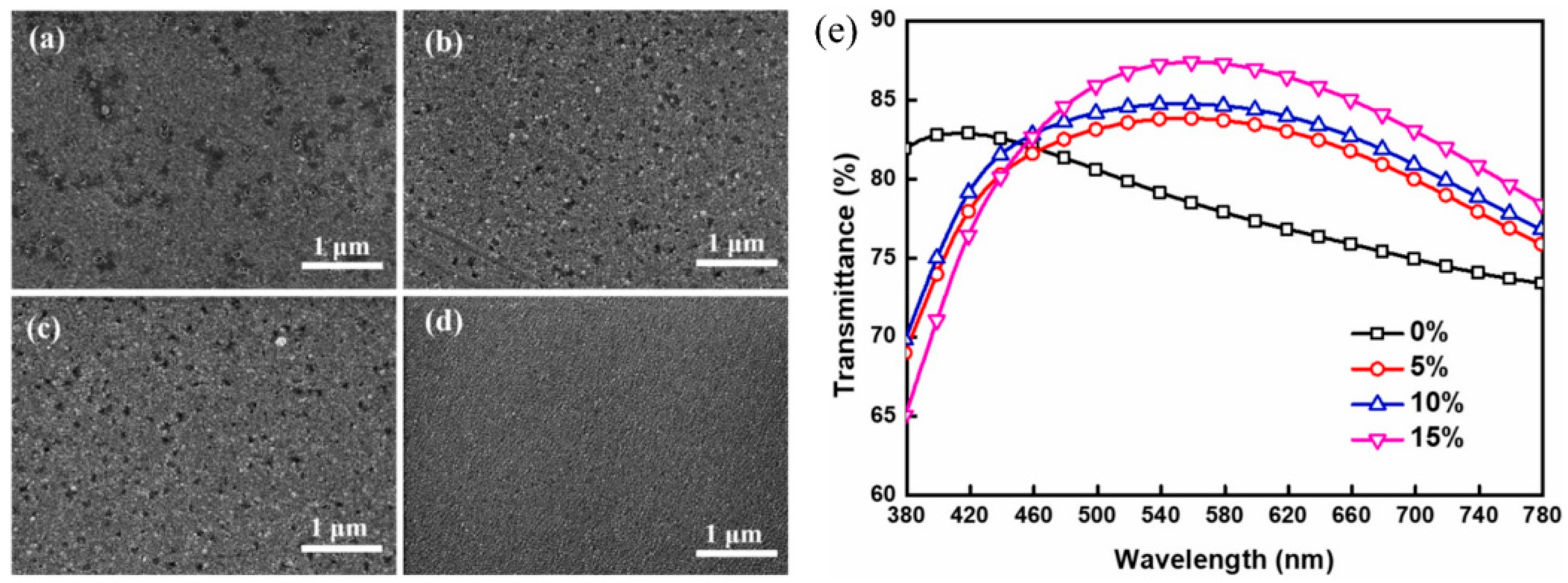
Zhang et al. [54] introduced O2 only in the initial stage of sputtering to create a AgOx layer between Ag film and dielectric substrate and studied the influence of oxygen flow rate on the morphology of Ag layer and the transmittance. As shown in Figure 10, at 15% oxygen concentration, the surface roughness is the smallest (Figure 10d), and the Tav reached 83.03% with a Rs of 17.77 Ω/sq. Reducing oxygen content to 5% (Figure 10b) significantly reduced the Rs (12.21 Ω/sq) with a marginal decrease in Tav (80.95%).
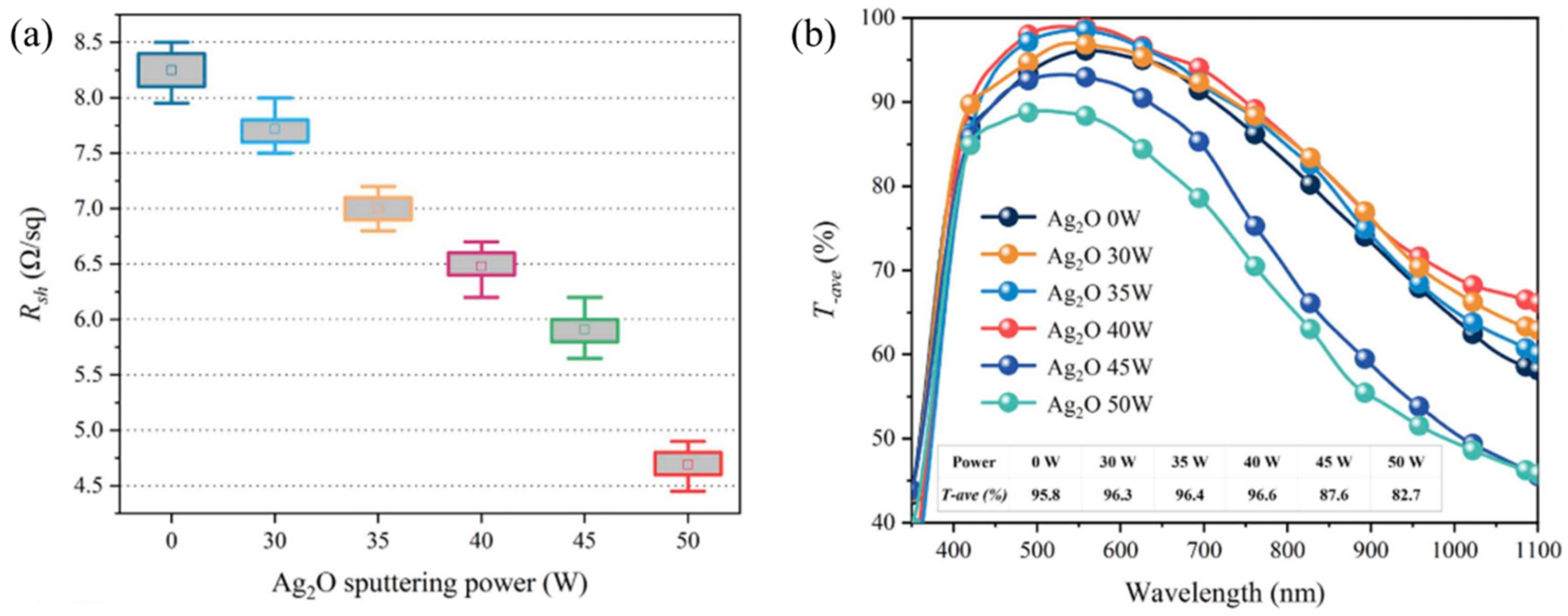
In 2024, Li et al. [55] introduced Ag2O directly into ZnO/Ag/ZnO (ZAZ) films by magnetron sputtering. As shown in Figure 11, through tuning the sputtering power of the forming Ag2O, the Rsh and Tav of ZnO/Ag-Ag2O/ZnO (ZAAZ) thin films reached 6.5 Ω/sq (red in Figure 11a) and 96.6% (red line in Figure 11b) corresponding to sputtering power of 40 W, resulting in a FOM value as high as 104.1 × 10⁻³ Ω. The FOM value was much higher than those where oxygen was added in the initial or throughout the whole deposition process.
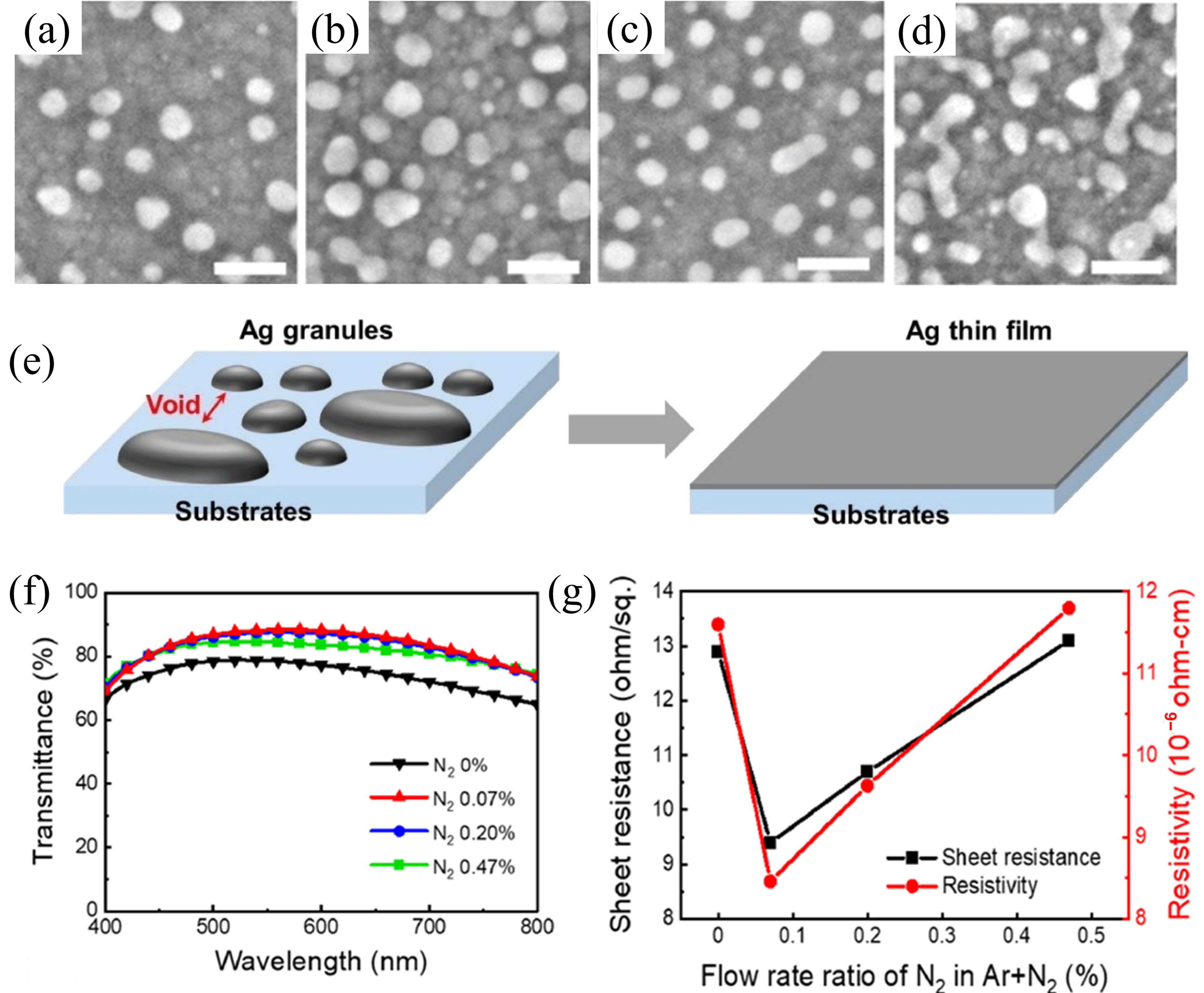
For N2 gas-assisted deposition, it was found that nitrogen can lower the conductivity threshold thickness more significantly than oxygen. In 2018, Zhao et al. [56], for the first time, introduced a small amount of N2 during sputtering of the Ag thin films with 45 sccm Ar and 16 sccm N2, and the obtained AgNx thin films had a tCT smaller than 5.4 nm. The ZnO/AgNx/ZnO flexible transparent electrodes prepared on PET substrates had a FOM value of 45.95 × 10⁻³ Ω−1. As shown in Figure 12, when the thickness of the AgNx thin film was 0.7 nm (Figure 12c), the AgNx thin film had a nucleation density larger than the undoped Ag thin film (Figure 12a). When the thickness was increased to 1.5 nm, the neighboring islands in the AgNx thin film (Figure 12d) began to form irregular bridge-like connections, but did not do so in the undoped Ag thin film (Figure 12b). This demonstrates that N2 gas addition during the sputtering process can promote smooth and flat Ag surface formation, as shown by the sketch in Figure 12e [44].
Nitrogen content is a sensitive parameter. In 2022, Kim et al. [44] prepared AZO/AgNx/AZO transparent electrodes on PI substrates by introducing a small amount of N2 during sputtering to deposit Ag thin films. As shown in Figure 12f,g, when the ratio of N2 to Ar was 0.07%, the Tav of the AZO/AgNx/AZO transparent electrode was 82.4%, the Rs was 8.5 Ω/sq, and the FOM value was 16.98 × 10⁻³ Ω−1, which is a significant improvement to be achieved in the optoelectrical performance compared with the AZO/Ag/AZO transparent electrode.
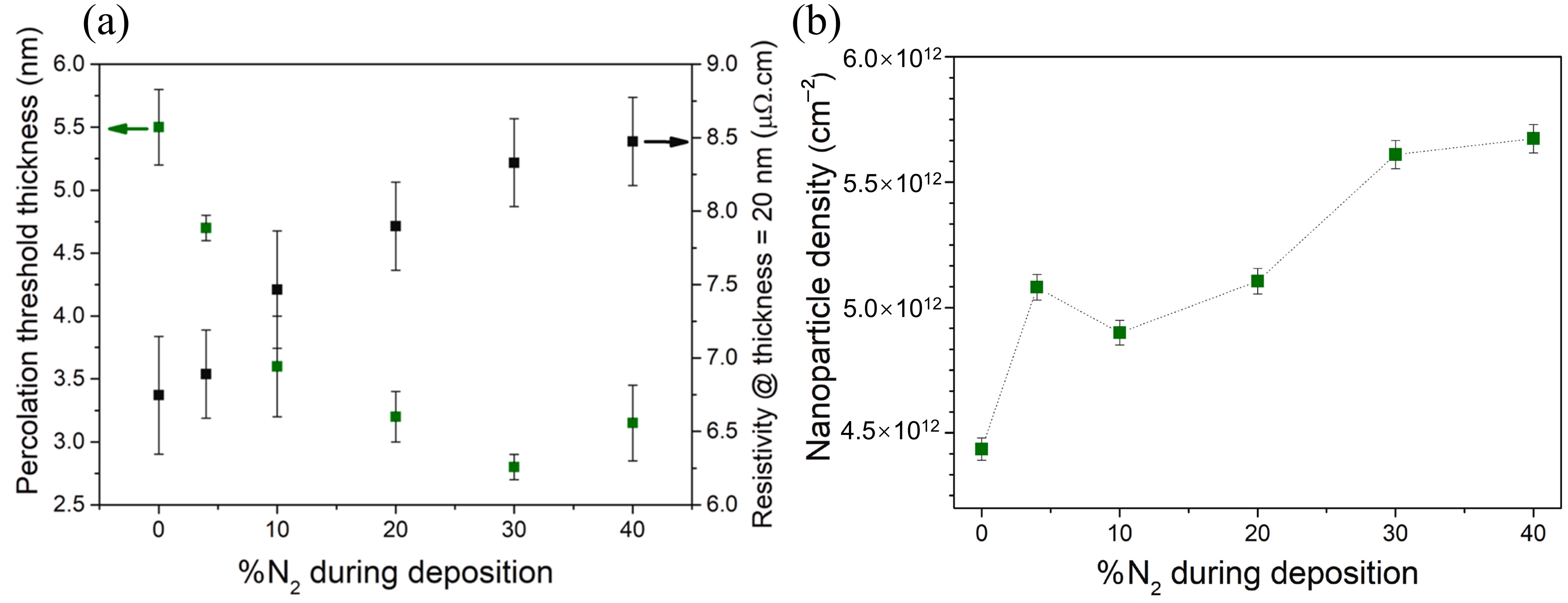
It is worth noting that normally, when tCT of the metal film decreases, the conductivity of the thin film will be elevated; however, this is not necessarily the case for the addition of nitrogen during the preparation of the metal film. In 2024, Zapata et al. [57] deposited Ag thin films on amorphous SiO2 using magnetron sputtering. With the addition of N2 to Ar, the tCT of the Ag thin film was drastically reduced, but the electrical conductivity of the Ag thin film was decreased significantly (Figure 13a). It was found that there was almost no chemical reaction between N2 and Ag. Activated N species formed by ionizing nitrogen during the deposition process were dynamically adsorbed on the silver thin film. This dynamically adsorbed species reduces the surface energy of the Ag thin film. More nuclei were formed (Figure 13b), and thus the tCT was reduced. At the same time, it leads to competition between the Ag (111) and Ag (100), causing structural changes in the Ag thin film, for example, generating grain boundaries which hinder electron transport and affect the electric resistivity. Therefore, the control of the gas amount is rather difficult, and the mechanism is more complex than expected.
Overall, O2 or N2 gas can be introduced in the initial or during the whole deposition process to reduce tCT and improve the optical performance. It is better to introduce O2 in the early stages. The flow rate or the ratio of the added gas to Ar is an important parameter. The added O2 or N2 can increase the nucleation density such that the tCT is reduced, but too much added gas will reduce the conductivity of the Ag layer due to oxide formation or grain boundary generation. No chemical reaction between N2 and Ag takes place. The activated N species is only dynamically adsorbed on the silver thin film and reduces the surface energy of the Ag thin film.

2.4. Metal Doping

Metal doping is usually achieved through co-sputtering in the deposition of Ag thin film. Heterogeneous metals (M) of high binding energy with oxygen are doped into the Ag thin film. An M-O bond is formed due to it having a stronger bonding strength than the Ag-O bond, lowering the surface energy and thus improving the wettability and preventing the agglomeration of the Ag thin film; or the dopant atoms serve as additional nucleation sites, resulting in increased nucleation density and reduced Ag nanoparticle size. Commonly used metals are Al [38,58,59,60], Cr [61], Cu [62], and Ni [63].
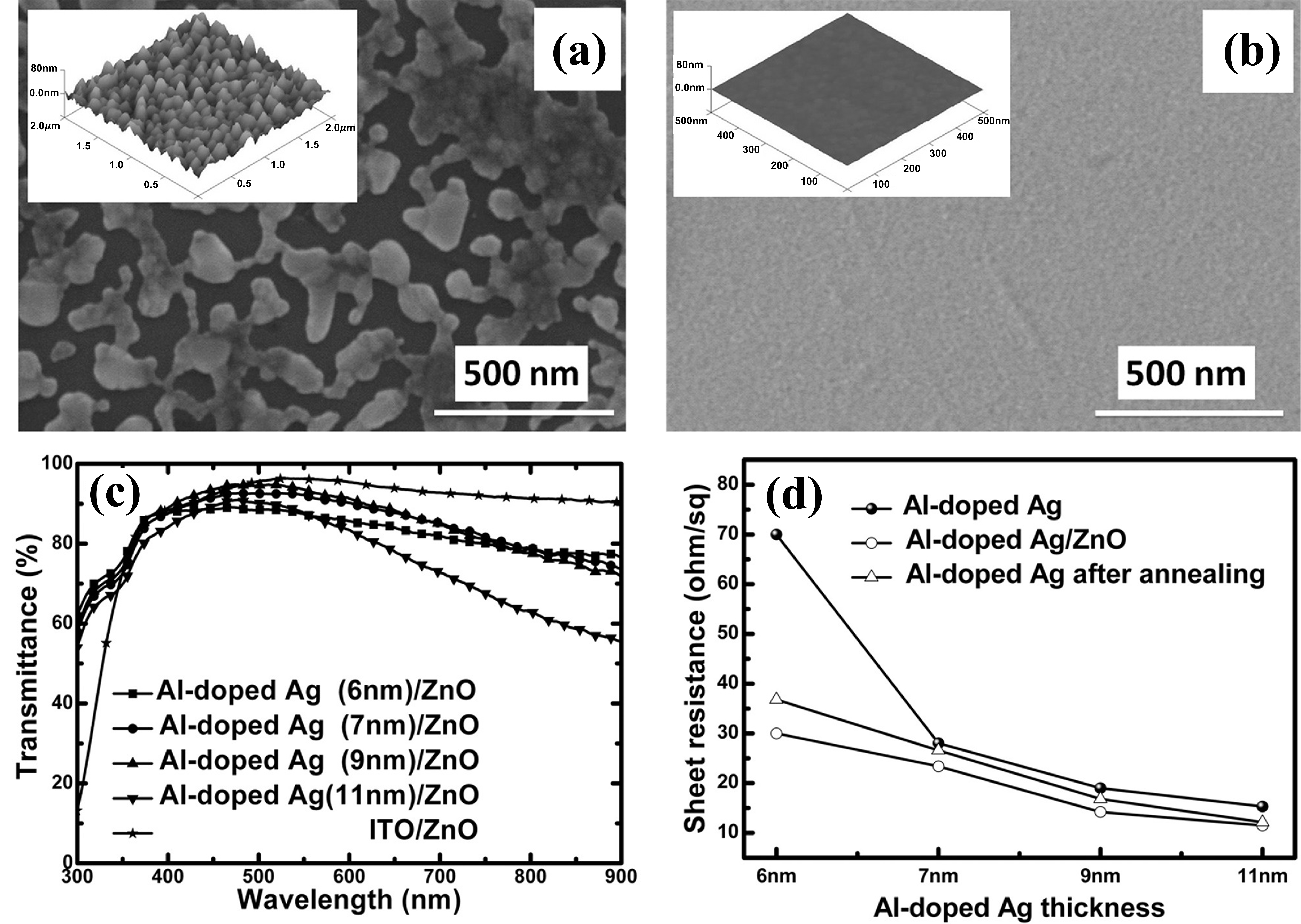
In 2014, Zhang and Gu et al. [58,59] doped Al into Ag by co-sputtering to prepare Ag:Al thin films on SiO2 substrate. As shown in Figure 14a,b, the surface roughness of 9 nm Ag:Al thin films was dramatically reduced from 10.8 to 0.82 nm. This is because the co-sputtered Al atoms increased the nucleation sites of Ag:Al thin films and prevented the agglomeration of Ag thin films. Compared with the 9.0 nm Ag thin film, the Tav of the 9.0 nm Ag:Al thin film at 550 nm was increased from 55% to 80%, and the Rs was reduced from 19.0 to 14.2 Ω/sq. However, the transmittance of the Ag:Al film in the visible light range was reduced when the atom ratio of Al to Ag was larger than 10%. When Ag:Al thin films were applied to DAD, FOM values were increased. For example, in 2015, Zhao et al. [60] applied Ag:Al thin films to Ta2O5/Ag:Al/ZnO transparent electrodes. The Ta2O5/7 nm Ag:Al/ZnO transparent electrodes prepared on PET substrates showed a transmittance of 96% at 550 nm, a Rs of 23.1 Ω/sq, and a FOM value of 28.78 × 10⁻³ Ω−1. In 2017, Zhang et al. [38] applied Ag:Al thin films to configure TiO2/Ag:Al/TiO2/MgF2 transparent electrodes, and high and flat transmittance spectra in the visible light and near-infrared wavelengths (400–1000 nm) with an Tav of 92.4%, a Rs of 20 Ω/sq, and a FOM value of 22.68 × 10⁻³Ω−1 were achieved.
Other metals, such as Cr [61], Cu [62], and Ni [63], have been doped into the Ag layer of DAD and have been demonstrated to improve the wettability of Ag thin films. The results are listed in Table 1. Two-metal doping was also tried. In 2021, Jang et al. [64] co-sputtered and prepared Ag:Ti:Cr (ATC) thin films. The co-deposited Ti and Cr atoms limited the agglomeration of the Ag thin film, reducing the tCT to below 6.0 nm. The Zn:SnOx/10 nm ATC/Zn:SnOx transparent electrode prepared on a PET substrate has a Tav of 89% in the visible light range, a Rs of 7.8 Ω/sq, and a FOM of 41.58 × 10⁻³ Ω−1. On the other hand, SnOx has also been doped. In 2020, Wang et al. [65] doped SnOx into an Ag thin film by co-sputtering to prepare an Ag:SnOx thin film. The tCT was as low as 6.0 nm. The Tav of AZO/6 nm Ag:SnOx/AZO transparent electrode prepared on PI substrate reached 88% in the visible light range, with a Rs of 10.8 Ω/sq. But the FOM value was only 25.79 × 10⁻³ Ω−1. In a related study, Li et al. [66] employed magnetron co-sputtering to incorporate Ag into the Cu layer to produce ZnO/Cu:Ag/ZnO (ZCAZ) electrodes. The Tav was 89%. When integrated into flexible CZTS solar cells (CSCs), these ZCAZ electrodes improved both device flexibility and photovoltaic performance.
According to these studies, by doping metals into the Ag layer, the roughness can be reduced with high efficiency, and the optic-electrical performance of DAD can be improved, but the FOM values are seldom higher than 60 × 10−3 Ω−1. The main reason is that the doped metal elements not only absorb incident light, resulting in low transmittance, but also increase the resistivity.
The difference between metal doping and gas additives was investigated by Zhao et al. [67] in 2025. They compared the effects of gaseous additives (O, N) and metallic additives (Cu, Zn) on the formation of ultrathin Ag layers on oxide substrates and found that the atomic-level O additive is the most effective in promoting the early cluster-to-layer transition of Ag, optimizing the optoelectronic properties and thermal stability. The experiments showed that the O additive can make the Tav of a 6–7 nm-thick Ag layer exceed 85%, while maintaining a low resistance of 22 Ω/sq with excellent thermal stability. In contrast, the metal additives (e.g., Cu, Zn) can improve the wettability, but high concentration leads to an increase in optoelectronic loss (Figure 15). DFT calculations show that O inhibits 3D agglomeration and promotes 2D layer growth by reducing Ag surface and interface free energy, which is better than the interfacial free energy modulation alone that is offered by metal additives.

2.5. Pre-Deposited Seed Layer

The pre-deposited seed layer technique is the deposition of a thin seed layer prior to Ag film growth. The seed layer material is selected for either high intrinsic surface energy or strong bonding affinity with Ag atoms to reduce the interfacial energy mismatch between the dielectric substrate and Ag thin film, preventing the agglomeration of the Ag layer, or the seed layer acts as nucleation sites to prevent the diffusion of Ag atoms. An Ag thin film with a small tCT, a low surface roughness, and a high electrical conductivity can be fabricated.
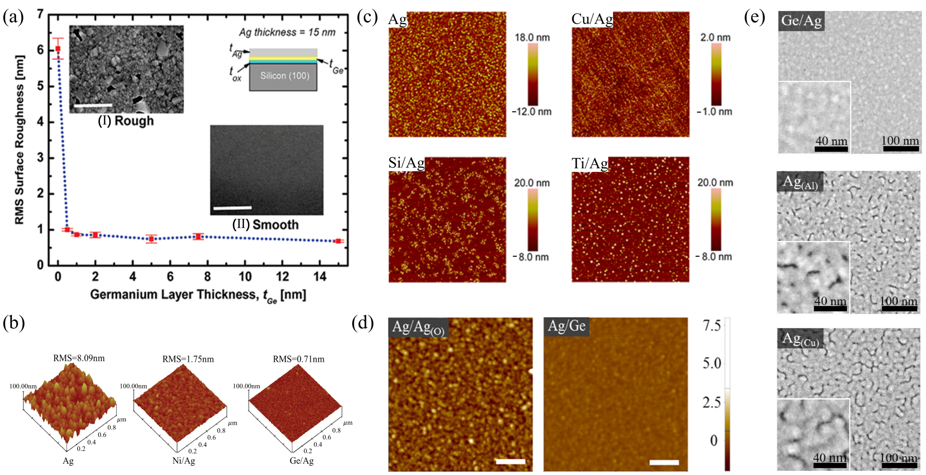
The commonly employed seed layers include Ge [36,41,68,69], Ni [69], Ti [70,71,72], Cu [67,68,69,70,73,74,75,76,77,78,79], Si [73], Cr [80], Au, etc. In 2009, Logeeswaran et al. [41] prepared Ge/15 nm Ag samples on a SiO2 surface using a Ge seed layer. As illustrated in Figure 16a, the addition of a Ge seed layer dramatically reduced the surface roughness from 6.1 to 0.8 nm, with nearly all of the improvement coming from the first 0.5 nm of Ge (red dot is data, blue dot line is guidance). This remarkable improvement originates from the fact that the Ge seed layer acts as a high-nucleation-density template, increasing the nucleation density of the silver atoms deposited on it, and thus it reduces the AgNPs’ size and the surface roughness of the silver thin films.
Liu et al. [68] compared the effects of the seed layer of Ge and Ni using 2 nm Ge/52.72 nm Ag and 2 nm Ni/56.84 nm Ag multilayer structures on Si substrates. As shown in Figure 16b, Ge is better than Ni, and the surface roughness of Ag nanofilm decreased from 8.09 to 0.71 nm.
Formica et al., in 2013 [73], compared the effects of Cu, Si, and Ti seed layers. The surface morphologies of Cu/Ag, Si/Ag, and Ti/Ag samples (1 nm seed layer/6 nm Ag) on the SiO2 surface are shown in Figure 16c. Among these, the 1 nm Cu/6 nm Ag sample exhibited superior wettability, with a surface roughness smaller than 0.5 nm lower than that of Si/Ag and Ti/Ag. This is because Cu has a larger surface energy than Ag and Si, and the Ag-Cu bond energy is larger than that of Ag-Ag, which suppresses the migration of Ag atoms. This was demonstrated by Li et al. [74], who utilized a 1 nm Cu seed layer to enhance Ag film wettability, and tCT smaller than 5 nm with an ultra-low surface roughness of 0.24 nm was obtained.
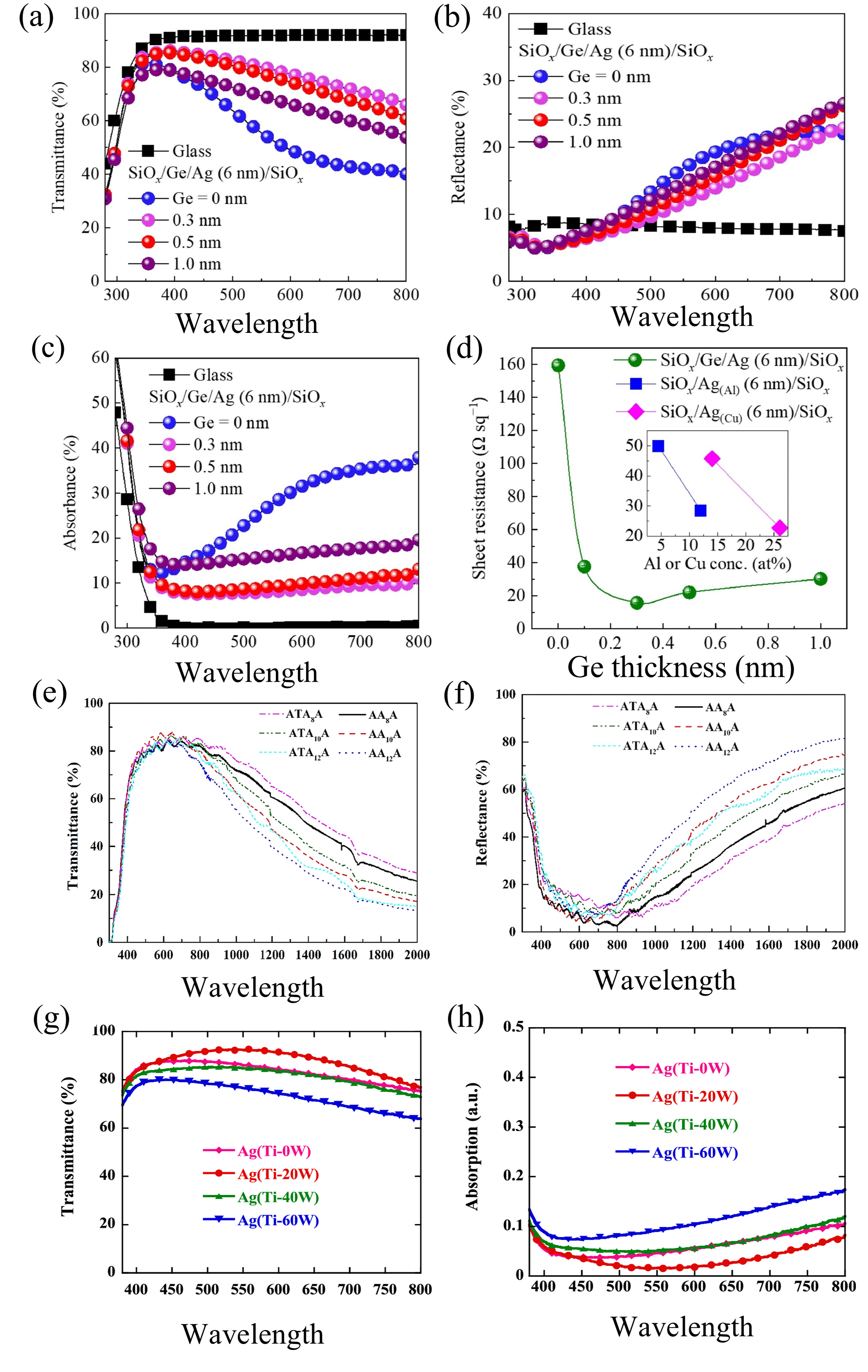
Zhao et al. compared the effect of the Ge seed layer with that of oxygen addition [81] ( the Tav of ZnO/Ge/Ag/ZnO is lower than that of ZnO/AgOx/Ag/ZnO) and with Al and Cu doping [37]. As shown in Figure 16d,e, the surface of Ag on Ge is the smoothest, and is better than oxygen addition and Al and Cu doping. By MD simulation, they suggested that the atomic-level Ge interlayer can actively migrate and mix into Ag and SiOₓ substrates during the early stage of Ag growth, which more efficiently promotes the cluster-to-layer transition than Cu and Al [37].
The core role of the Ge interlayer is to suppress cluster merging by decreasing the diffusion ability of Ag clusters on the surface, to reduce the rearranging dynamics of the tiny Ag clusters, and to reduce the interfacial and surface free energy through the inherent low-surface-energy characteristics of Ge [37]. These synergistic effects enable the fabrication of a continuous Ag layer with minimal surface roughness. This mechanism is obviously different from the commonly accepted mechanism of Ge seed layers increasing the nucleation density of the silver atoms deposited on them.
Ji et al. [70] recently revealed the regulation mechanism of the sub-nanometer Ti wetting layer on Ag thin-film growth over silicon oxide substrate through experiments and density functional theory (DFT) calculations. It is shown that the 0.7 nm-thick Ti wetting layer undergoes strong interfacial reactions with the substrate and forms a Ti-O-Si mixed-oxide interface. The non-stoichiometric TiOx formed by partial oxidation of the Ti layer enhances the binding force of Ag and Ti through electronic interactions, which induces the growth of the Ag layer in a two-dimensional (2D) laminar pattern, resulting in the formation of a continuously smooth Ag layer. An ultrathin Ag layer electrode with a Tav of 93.8% and an Rs as low as 8.29 Ω/sq has been prepared.
However, Ge and Ti seed layers are seldom applied to DAD. Among various seed layers, the Cu seed layer is the best choice. In 2023, Bernède et al. [75] applied a Cu layer to DAD transparent electrodes for the first time. The optical transmittance spectrum of the 20 nm ZnO/4 nm Cu/6 nm Ag/MoO3 transparent electrode on a glass substrate was significantly broadened. A Ta of 81%, a Rs of 7.5 Ω/sq, and a FOM value of 16 × 10−3 Ω−1 was achieved. In 2015, Mouchaal et al. [76] investigated the influence of the thickness of Cu seed layer on the transmittance of ZnS (50 nm)/Cu (x nm)/Ag (9 nm)/ZnS (50 nm) and found that 3 nm is the best. A Tav of 85%, a Rs of 4.8 Ω/sq, and a FOM of 41.02 × 10⁻³ Ω−1 were achieved (Figure 17a). The shining feature is that the transmittance between 450 and 700 nm is nearly the same (green line in Figure 17a). In 2021, Liu et al. [77] prepared MoOx/Cu/Ag/MoOx (MCAM) transparent electrodes on glass to optimize the Cu seed layer thickness. The Tav of the MCAM transparent electrode reached the maximum value when the thickness of Cu was 1 nm (blue line in Figure 17b). Further decreasing the thickness of the Cu seed layer significantly reduced the conductivity of the transparent electrode. For example, as shown in Figure 17c, when the thickness decreases from 1 nm to 0.8 nm and then to 0.6 nm, the Rs of the MCAM transparent electrode increases from 9.45 Ω/sq to 20.8 Ω/sq and then to 33.2 Ω/sq. Overall, the MCAM transparent electrode has the highest optic-electric performance when the thickness of the Cu seed layer is 1 nm. The Tav in the visible light range is 62.32%, the Rs is 9.45 Ω/sq, and the highest FOM value is 9.35 × 10⁻³ Ω−1.
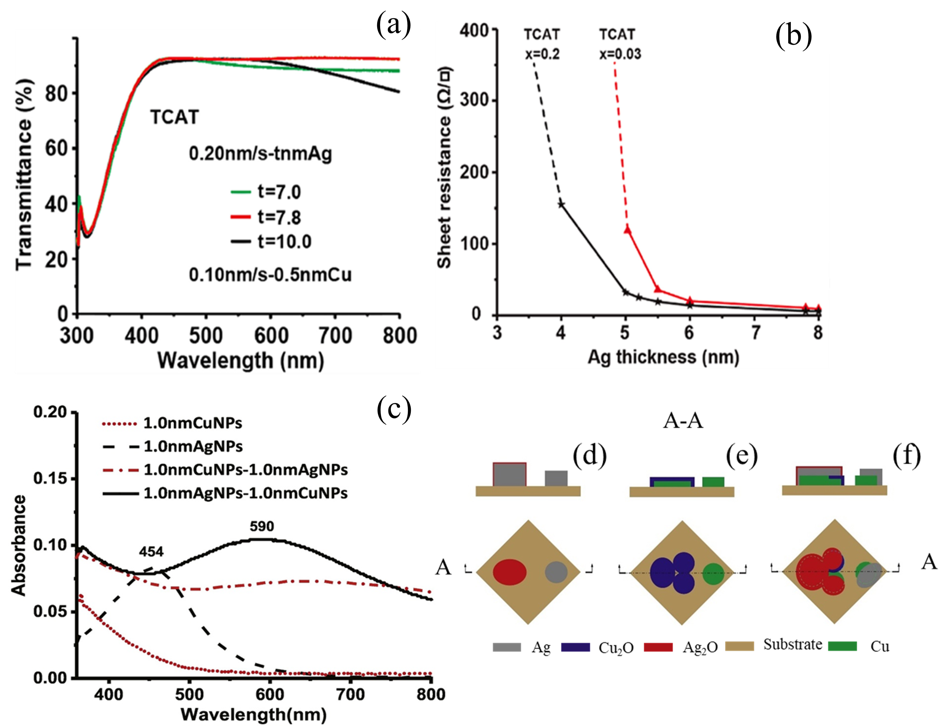
In the same year, our group [24] prepared TiO2/0.5 nm Cu/Ag/TiO2 (TCAT) transparent electrodes on glass substrates. Using a 0.5 nm Cu seed layer, combined with regulating deposition parameters of the Ag thin film, TCAT transparent electrodes achieved transmittance spectra nearly parallel to the x-axis in the wavelength range of 400–800 nm, with an average transmittance of 92.5% ± 0.5% (Figure 18a, red line). The Rs was as low as 6.2 Ω/sq (Figure 18b), and the FOM was as high as 71.51 × 10⁻³ Ω−1. HRTEM and XPS analyses [78] revealed that the epitaxial-like growth of AgNPs on the Cu seed layer, enabled by their similar lattice constants, suppressed the LSPR of AgNPs (Figure 18c, dot-dash line). Figure 18d,e shows the schematic principal diagrams of silver and copper nanoparticles (average thickness: 1 nm) on glass substrates. Both exhibit columnar growth morphology. However, the copper nanoparticles are flatter than the silver nanoparticles; this means that the silver nanoparticles are more agglomerated than the copper nanoparticles. When silver was deposited on the surface of copper nanoparticles (denoted as 1.0 nm CuNPs-1.0 nm AgNPs, Figure 18f), it grew in a highly wettable manner. The agglomeration of AgNPs and their LSPR effect were effectively suppressed. Therefore, damping the LSPR by lattice matching is also one of the important mechanisms to improve the optical transmittance of the DAD transparent electrode. This principle has been further validated by Zhang et al. [54], who demonstrated that lattice mismatch at the interface between AZO and AgOx/Ag decreased with the increase in oxygen content, which helped to increase the wettability of the Ag thin films on the substrate surface. However, little attention has been paid to lattice match.
To develop high-performance flexible DAD transparent electrodes for chalcogenide solar cell applications, Jiang et al. [79] prepared an AZO/Cu/Ag/AZO structure on a PET substrate. Their study (Figure 19a) revealed that the optimal 0.1 nm Cu seed layer achieved average visible transmittance of 90.77%, Rs of 9.9 Ω/sq (Figure 19b), and a FOM value of 38.35 × 10⁻³ Ω−1 (Figure 19c).
According to the reports mentioned above, the Cu seed layer can help the DAD to obtain excellent optical performance; not only is the transmittance large, but also the line of the transmittance between 400 and 800 nm can be a line parallel to the X-axis. This cannot be obtained using a Ge or Ti seed layer. As shown in Figure 20, for the Ge seed layer, according to the optical transmittance spectra (Figure 20a–d) provided by refs [36], the reflectivity (Figure 20b) of DAD using Ge as a seed layer is large, and the sheet resistance (Figure 20d) is also around 20 Ω, which is relatively larger than Cu as a seed layer. For the Ti seed layer, according to the optical transmittance spectra provided by refs [71,72], the reflectivity (Figure 20f) is relatively high; and also the average absorbance is about 5% (Figure 20h), indicating that the LSPR damping effect of Ti is not strong, therefore, high transmittance in the wavelength range of 650–800 nm can’t be obtained. Among various seed layers, the Cu seed layer is the best choice. Aside for its effectiveness, the fact that it can be deposited by simple resistance-heating is also a big advantage.
In summary, a Ge seed layer is the best to reduce the surface roughness of Ag thin film, but it is unsuitable to be applied in the DAD electrode, due to the large reflectivity and large resistance. A Cu seed layer is the best choice, and a FOM value as high as 71.51 × 10⁻³ Ω−1 has been achieved when the thickness of the Cu seed layer is 0.5 nm and TiO2 is the dielectric layer. Further reducing the thickness of the Cu seed layer decreases the light absorption of the Cu seed layer, but it reduces the wettability of the Ag thin film, which seriously degrades the optoelectronic performance of the DAD transparent electrodes. Lattice match between the Ag layer and the substrate promotes the wettability of the Ag layer.

3. Progress on the Dielectric Layers of DAD Transparent Electrodes

Too many dielectric layer materials, such as ZnO, SnO2, Nb2O5, TiInZnO, MoO3, WO3, Al-doped ZnO, Al2O3, ZrON, ZnSnO, etc., have been developed. The ones that are commonly studied are ZnO, Al (ZAO or AZO), TiO2, and MoO3 because they are very stable, their bandgaps are wide, and their energy levels are suitable for solar cells, organic light-emitting diodes (OLEDs), touch screens, etc. For example, the high work function between 4.7 and 6.9 eV of MoO3 makes it an efficient hole-selective interfacial layer in flexible opto-electro devices. AZO thin films, both transparent and conductive, are used as alternative electrodes to ITO in many cases. TiO2 has a bandgap of 3.2 eV, a high refractive index (~2.7), and good chemical stability. It is the main material of DSSC and perovskite solar cells. The TiO2/Ag/TiO2 transparent electrode [82,83] is of high transmittance and low Rs, and has drawn wide interest. This part just lists several examples to indicate the progress on the dielectric layers of DAD transparent electrodes.

3.1. Progress in DAD with Same Dielectric Layer Materials

In 2013, Abachi et al. [84] prepared MoO3/Ag/MoO3 (MAM) transparent electrodes on PET substrates using the vacuum evaporation deposition technique. Combined with the regulation of the deposition rate of Ag, the electrodes exhibited a Tav of 72%, comparable to that of ITO electrodes, while achieving a lower Rs of 13 Ω/sq (vs. ~50 Ω/sq for ITO) and a FOM value of 2.90 × 10⁻³ Ω−1. In 2021, by varying the ratio of Ar/O2 and the sputtering power, the transmittance of MAM at 550 nm reached 72%, and the FOM value reached 5.70 × 10⁻³ Ω−1 [85]. The introduction of O2 gas during sputtering suppressed the formation of MoOx (x < 3), eliminating strong visible-light absorption caused by Mo5+ [86]. In 2022, Goetz et al. [87] fabricated MTO/Ag/MTO on a PET substrate using a magnetron sputtering technique, where the dielectric layer consisted of TiO2-doped MoOx (MTO). By adjusting the MTO thickness, they achieved a transmittance at 550 nm of 87.8%. The FOM value reached 45.4 × 10⁻³ Ω−1. Meanwhile, the transparent electrode exhibited exceptional stability: When immersed in water for 600 s, the MoOx sample was basically completely dissolved, while the MTO sample was only dissolved by about 5%. This is due to the fact that Ti4+ reduces the cationic charge in the MoO3 film layer and lowers the surface acidity, thus suppressing the hydrolysis process [88].
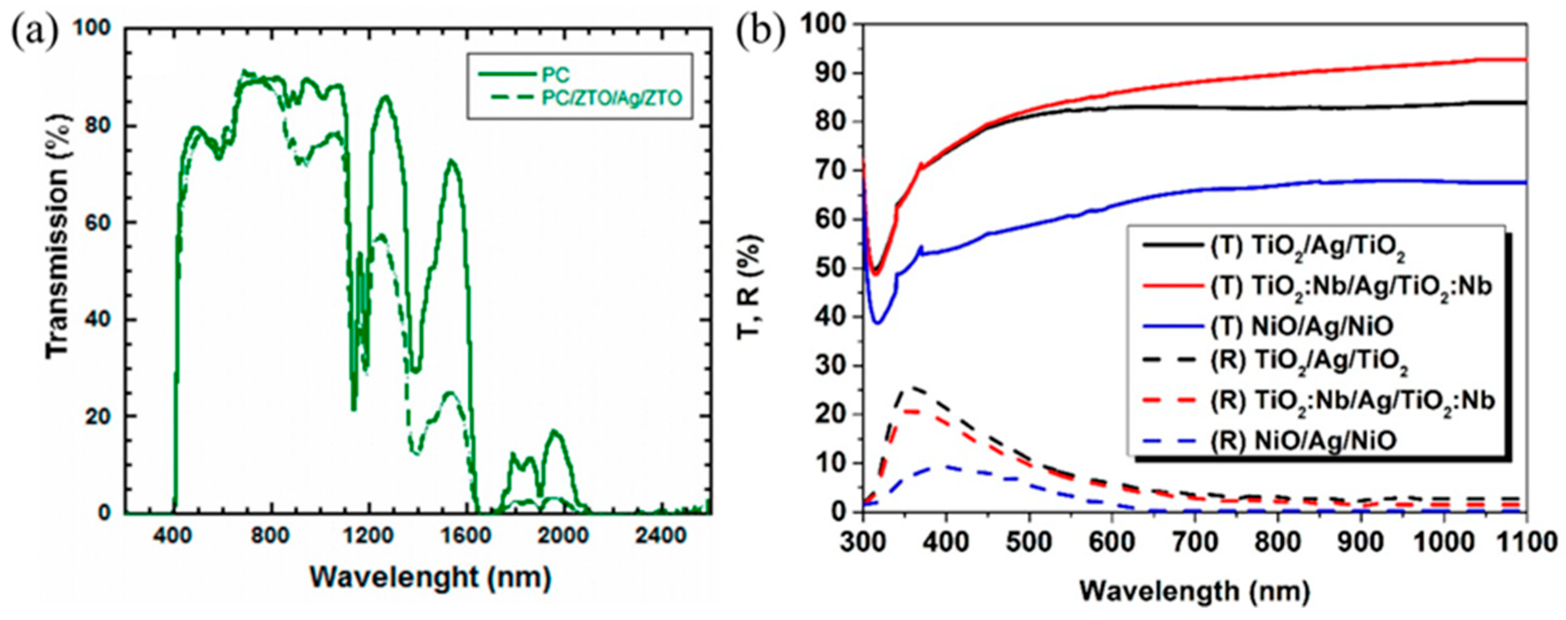
In 2018, Yan et al. [89] used AlH3-doped ZnO (HAZO) as the dielectric layer and prepared HAZO/Ag/HAZO flexible transparent electrodes on PEN substrates using the magnetron sputtering technique. A transmittance of 88.2% at 550 nm, Rs of 6.37 Ω/sq, and FOM value of 44.7 × 10⁻³ Ω−1 were achieved. In 2021, Ekmekcioglu et al. [90] fabricated ZTO/Ag/ZTO (ZAZ) transparent electrodes on both PET and PC substrates. The ZAZ structure (green dashed line in Figure 21a) exhibited exceptional optical performance with transmittance exceeding 100% in the 500–600 nm range, surpassing that of PC substrates (green solid line in Figure 21a). This was attributed to the fact that the refractive index and the thickness of the ZTO were well matched with the optical parameters of the Ag thin film, and the light reflections at the interfaces of the ZAZ were completely suppressed. The electrode achieved an unprecedented FOM value of 83.00 × 10⁻³ Ω−1. In 2025, Li et al. [91] prepared BMZO (B-Mg co-doped ZnO)/15 nm Ag/BMZO multilayer films. The Tav of the as-prepared BMZO/Ag/BMZO composite film was increased to 90%, and the resistivity was 4.55 × 10⁻⁴ Ω cm.
In 2021, Hrostea et al. [92] prepared TNO/Ag/TNO flexible transparent electrodes on PET substrates using Nb-doped TiO2 (TNO) dielectric layers. The TNO-based electrodes demonstrated superior performance compared to the undoped TiO2/Ag/TiO2 structure, achieving 84.17% transmittance at 550 nm (vs. 81.83% for the undoped counterpart, Figure 21b). These enhancements stem from two effects of Nb doping: (1) widening of the optical bandgap and modification of the refractive index, which minimizes interfacial light reflection; (2) introduction of Nb5+ as an n-type dopant in the TNO dielectric layer, which improves electrical conductivity. Consequently, TNO/Ag/TNO exhibited a very low Rs of 11.9 Ω/sq, nearly 70 times lower than the undoped TiO2/Ag/TiO2 electrodes (833.3 Ω/sq). In 2022, Goetz et al. [93] used DC magnetron sputtering from a conductive oxide target that allowed for high deposition rates, resulting in transparent TNO films even in an inert Ar atmosphere and without substrate heating. The combination with ultrathin Ag layers yields flexible DAD electrodes on a PET substrate with visible transmittance above 70% and sheet resistance below 10 Ω/sq.

3.2. Research Progress on DAD Flexible Transparent Electrodes with Different Dielectric Layer Materials

In 2014, Chiu et al. [94] prepared TiO2/Ag/SiO2 transparent electrodes on glass substrates through thickness optimization (25 nmTiO2/10 nm Ag/70 nm SiO2). An average transmittance of 89% in the range of 400–700 nm and a FOM value of 47.97 × 10⁻³ Ω−1 was achieved. Among many electrode structures, the transmittance of asymmetric dielectric design TiO2/Ag/SiO2 with different dielectric materials on both sides is significantly higher than that of symmetric configurations of TiO2/Ag/TiO2 and ZnO/Ag/ZnO with the same dielectric materials (Figure 22a). This is because of the high refractive index of the bottom TiO2 layer and the low refractive index of the top SiO2 layer, which significantly suppress interfacial light losses.
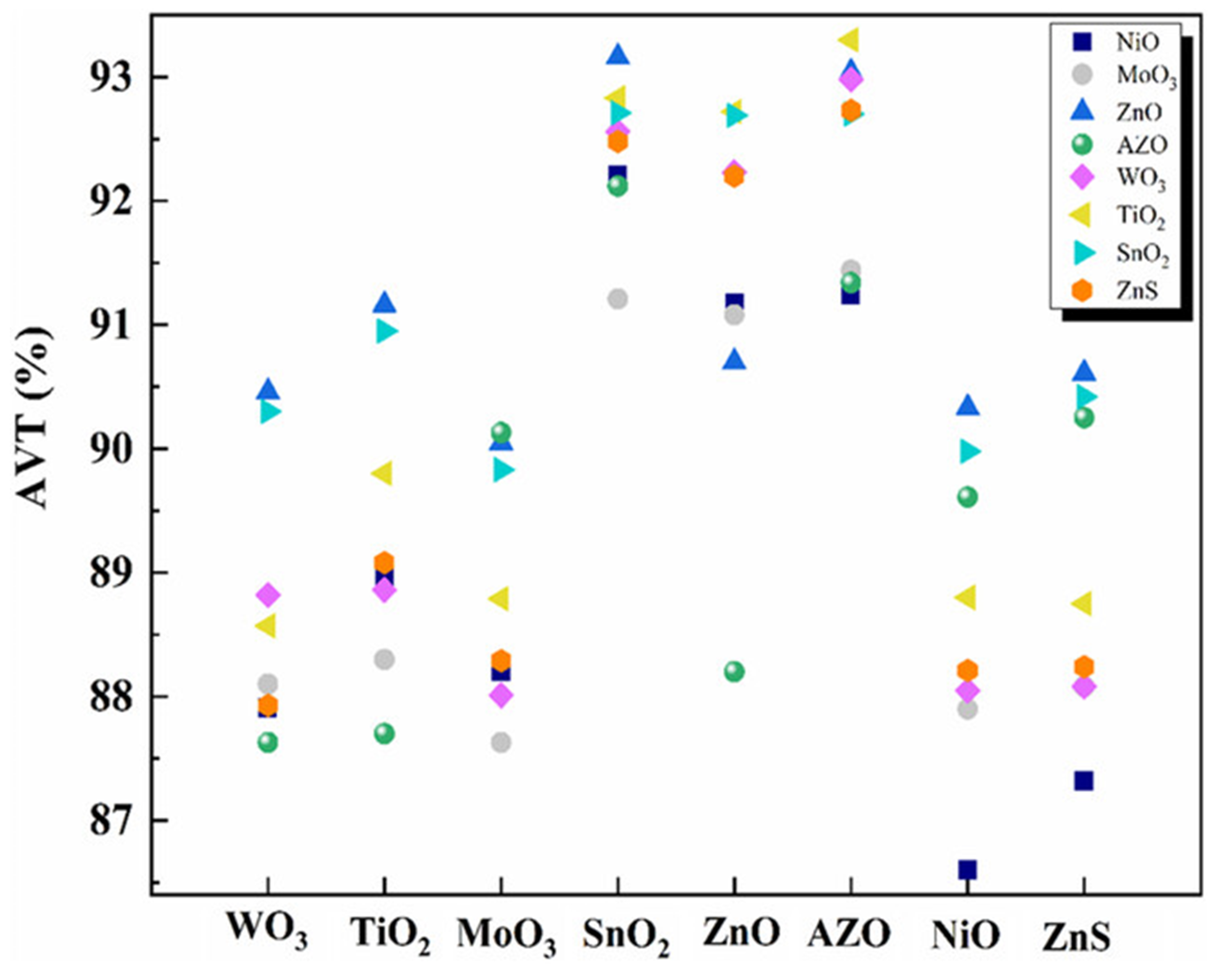
In 2015, Formica et al. [95] prepared a 34 nm TiO2/8 nm Ag/40 nm AZO flexible transparent electrode on an ultrathin glass flexible substrate. The Tav in the range of 400–700 nm reached 87.7%, and the FOM value reached 42.72 × 10⁻³ Ω−1. In 2019, Kinner et al. [96] prepared 27 nm TiO2/10 nm Ag/51 nm AZO flexible transparent electrodes on PET flexible substrates, and the Tav in the range of 400–700 nm was increased to 94%, and the FOM value was as high as 100.23 × 10⁻³ Ω−1. Combined with the Cu seed layer technique, in 2020, Ji et al. [97] prepared 24 nm ZnO/6.5 nm Ag-Cu/56 nm Al2O3 flexible transparent electrodes on PET substrates. The Tav in the range of 400–700 nm was higher than that of the substrate, indicating Tav exceeding 100% (Figure 22b). In 2023, Rani et al. [98] evaluated the optical performance of 64 different combinations of DAD transparent electrodes based on ZnO, AZO, TiO2, MoO3, WO3, NiO, SnO2, and ZnS dielectric layers by using transfer matrix simulations. The study fixed the Ag interlayer thickness at 9 nm and maintained equal thickness for both dielectric layers. As shown in Figure 23, among the many combinations, the TiO2/Ag/AZO transparent electrode had the highest optical performance, with a Tav of 93.3% in the range of 400–700 nm.
Figure 22. (a) Effect of the materials of dielectric layers on the transmittance of DMD. Comparison of transmittance spectra of DMD structures with different metal and dielectric layers [94]. (b) Transmittance over 100% is predicted. Calculated (red solid curve) and measured (blue dashed curve) absolute transmittance from 400 to 700 nm of the designed DMD transparent electrode PET substrate/24 nm ZnO/6.5 nm Cu-doped Ag/56 nm Al2O3. Inset presents the configuration of the designed DMD electrode [97].
Coatings 15 01370 g022
Figure 23. Graphical representation of the calculated average visible transparency (AVT) of various possible combinations of DMD transparent electrodes. Different shapes in the legend represent the bottom oxide layer, whereas the X-axis shows the corresponding overcoat oxide layer in the DMD stack [98].
Coatings 15 01370 g023
In addition to common dielectric layers, M. Socol et al. [99] investigated the preparation and performance optimization of reduced graphene oxide (RGO)-based multilayer transparent electrodes, RGO/Ag/ZnO. By adjusting the parameters of RGO concentration and laser pulse deposition, the Tav of RGO/Ag/ZnO multilayered electrodes reached 82%–85%, and the Rs was as low as 10.6 Ω/sq, which was about 50% lower than that of ZnO/Ag ZnO/Ag/ZnO multilayer electrode.

4. Summary and Outlook

DAD transparent electrodes based on ultrathin metal Ag film possess high optical transmittance, high electrical conductivity, high chemical stability, and excellent mechanical flexibility, and they will have a wide range of applications in flexible photovoltaic devices such as solar cells, light-emitting diodes, electrochromic devices, and transparent heating devices.
The key to improving the optical properties of DAD is to dampen the LSPR of AgNPs, and the key to improving the electrical properties is to reduce the tCT. Strategies based on preventing silver atom agglomeration and reducing the size of AgNPs not only dampen the LSPR but also reduce the tCT. The four kinds of techniques that were developed were plasma irradiation, gas-assisted deposition, metal doping, and seed layer technology. Metal doping dopes metal elements during the whole deposition of the Ag layer, and seed layer technology deposits a thin layer of metal before the deposition of the Ag layer. The two are highly efficient in reducing the tCT and the surface roughness, but due to the absorbance or reflectivity of metal elements, the optical performance is not as good as expected, resulting in low FOM values. We suggest that seed layer slight oxidation is promising for future developments [100].
Gas-assisted deposition introduces oxygen or nitrogen in the initial stage or during the whole deposition stage to change the chemical state of AgNPs so that the agglomeration of AgNPs can be lowered. Good results have been achieved; however, controlling the amount of gas during gas-assisted deposition is difficult. Specifically, the effect of damping the LSPR of AgNPs is much weaker than metal doping and seed layer technology. Plasma irradiation modifies the surface of the Ag layer or the dielectric layers, demonstrating the most effective approach, with FOM values larger than 100 × 10−3 Ω−1, which are much higher than the other three approaches; this has significant potential for future research. The pros and cons of different approaches are summarized in Table 2.
The research on the dielectric layer has been relatively complete and effective. We suggest future efforts could focus on integrating additional functional coatings, such as anti-reflection or self-cleaning layers, into DAD electrodes. The exploration of new dielectric materials, such as graphene-enhanced layers, also holds promise.
We end this review with some broader suggestions about future research directions. Firstly, damping the LSPR of AgNPs using a metal layer with a lattice that is matched with that of the silver layer is also promising. Based on this mechanism, more techniques can be developed. Secondly, good results can be achieved by combining two kinds of approaches for damping the LSPR of AgNPs, or one of the four kinds of technologies combined with dielectric layer materials [101]. Thirdly, computational simulation based on MD is very important. On the one hand, it helps to disclose the mechanisms behind phenomena and deepens our understanding; on the other hand, through simultaneous optimization of chemical stability and compatibility between the dielectric layers and the Ag thin film, it can advance DAD electrode performance. Finally, application in real devices is very exciting and is waiting to be explored.

Author Contributions

Y.W. and Y.N.: Investigation, data curation, formal analysis, writing—original draft, and writing—review and editing. S.W., C.L., and L.Y.: Data curation, and formal analysis. C.W.: Conceptualization, data curation, and writing—review and editing. P.M.: Conceptualization, formal analysis, and writing—review and editing. Y.F.: Conceptualization, data curation, formal analysis, supervision, and writing—review and editing. All authors have read and agreed to the published version of the manuscript.

Funding

This research received no external funding.

Institutional Review Board Statement

Not applicable.

Informed Consent Statement

Not applicable.

Data Availability Statement

Data will be made available on request.

Conflicts of Interest

The authors have no conflicts of interest to declare.

References

  1. Yan, Y.; Duan, B.; Ru, M.; Gu, Q.; Li, S.; Zhao, W. Toward Flexible and Stretchable Organic Solar Cells: A Comprehensive Review of Transparent Conductive Electrodes, Photoactive Materials, and Device Performance. Adv. Energy Mater. 2025, 15, 2404233. [Google Scholar] [CrossRef]
  2. Triolo, C.; Lorusso, A.; Masi, S.; Mariano, F.; Torre, A.D.; Accorsi, G.; Arima, V.; Leo, S.D.; Rinaldi, R.; Patané, S.; et al. Electromagnetic Mode Management in Transparent DMD Electrodes for High Angular Color Stability in White OLEDs. ACS Photonics 2025, 12, 2413. [Google Scholar] [CrossRef]
  3. Nomura, K.; Ohta, H.; Takagi, A.; Kamiya, T.; Hirano, M.; Hosono, H. Room-temperature fabrication of transparent flexible thin-film transistors using amorphous oxide semiconductors. Nature 2004, 432, 488. [Google Scholar] [CrossRef]
  4. Nguyen, V.H.; Papanastasiou, D.T.; Resende, J.; Bardet, L.; Sannicolo, T.; Jiménez, C.; Muñoz-Rojas, D.; Nguyen, N.D.; Bellet, D. Advances in Flexible Metallic Transparent Electrodes. Small 2022, 18, 2106006. [Google Scholar] [CrossRef]
  5. You, P.; Liu, Z.; Tai, Q.; Liu, S.; Yan, F. Efficient semitransparent perovskite solar cells with graphene electrodes. Adv. Mater. 2015, 27, 3632. [Google Scholar] [CrossRef] [PubMed]
  6. Zhang, J.; Hu, X.G.; Ji, K.; Zhao, S.; Liu, D.; Li, B.; Hou, P.X.; Liu, C.; Liu, L.; Stranks, S.D.; et al. High-performance bifacial perovskite solar cells enabled by single-walled carbon nanotubes. Nat. Commun. 2024, 15, 2245. [Google Scholar] [CrossRef] [PubMed]
  7. Su, X.; Wu, X.; Chen, S.; Nedumaran, A.M.; Stephen, M.; Hou, K.; Czarny, B.; Leong, W.L. A highly conducting polymer for self-healable, printable, and stretchable organic electrochemical transistor arrays and near hysteresis-free soft tactile sensors. Adv. Mater. 2022, 3, 2200682. [Google Scholar] [CrossRef] [PubMed]
  8. Chen, Z.; Yang, S.; Huang, J.; Gu, Y.; Huang, W.; Liu, S.; Lin, Z.; Zeng, Z.; Hu, Y.; Chen, Z.; et al. Flexible, Transparent and Conductive Metal Mesh Films with Ultra-High FoM for Stretchable Heating and Electromagnetic Interference Shielding. Nano-Micro Lett. 2024, 16, 92. [Google Scholar] [CrossRef]
  9. Zhu, X.; Xu, Q.; Li, H.; Liu, M.; Li, Z.; Yang, K.; Zhao, J.; Qian, L.; Peng, Z.; Zhang, G.; et al. Transparent Heaters: Fabrication of high-performance silver mesh for transparent glass heaters via electric-field-driven microscale 3D printing and UV-assisted microtransfer. Adv. Mater. 2019, 31, 1970229. [Google Scholar] [CrossRef]
  10. Park, Y.; Lee, S.; Tobah, M.; Ma, T.; Guo, L.J. Optimized optical/electrical/mechanical properties of ultrathin metal films for flexible transparent conductor applications: Review [Invited]. Opt. Mater. Express 2023, 13, 304. [Google Scholar] [CrossRef]
  11. Jeong, J.-A.; Kim, H.-K.; Yi, M.-S. Effect of Ag interlayer on the optical and passivation properties of flexible and transparent Al2O3/Ag/Al2O3 multilayer. Appl. Phys. Lett. 2008, 93, 033301. [Google Scholar] [CrossRef]
  12. Guillén, C.; Herrero, J. TCO/metal/TCO structures for energy and flexible electronics. Thin Solid Film. 2011, 520, 1. [Google Scholar]
  13. Girtan, M.; Negulescu, B. A review on oxide/metal/oxide thin films on flexible substrates as electrodes for organic and perovskite solar cells. Opt. Mater. X 2022, 13, 100122. [Google Scholar] [CrossRef]
  14. Malik, A.; Rani, S.; Guruprasad, S.; Basumatary, P.; Ghosh, D.S. Design and Optimization of Inverted Perovskite Solar Cells incorporating Metal Oxide-based Transparent Conductor. Adv. Theory Simul. 2025, 8, e00179. [Google Scholar]
  15. Masuda, Y.; Kiba, T.; Kawamura, M.; Abe, Y. Emission Wavelength Control Based on Coupling of Surface Plasmon and Microcavity Mode in Organic Light-Emitting Diodes with Metal/Dielectric/Metal Anodes. ACS Photonics 2024, 11, 2946. [Google Scholar] [CrossRef]
  16. Bae, S.; Jung, Y.; Pal, V.; Lee, J.K. Enhancement of Optical Transparency and Electrical Conductivity of IZO/Ag/IZO Multilayer Film by Intense Pulsed Light and its Effect on the Photovoltaic Performances of Perovskite Solar Cells. Adv. Sci. 2025, 12, 2501058. [Google Scholar]
  17. Nguyen, T.T.; Patel, M.; Kim, J. Multifunctional AZO/Ag (O)-Based Transparent Conductor for Flexible and Transparent Optoelectronics. Sol. RRL 2024, 8, 2400082. [Google Scholar]
  18. Sun, K.; Bao, Z.; Guo, X.; Zou, D.; Lv, Y.; Liang, J.; Liu, X. Crystallization Regulation and Defect Passivation of High-Performance Flexible Perovskite Light-Emitting Diodes Based on Novel Dielectric/Metal/Dielectric Transparent Electrodes. Adv. Optical Mater. 2024, 12, 2301752. [Google Scholar]
  19. Mohamedi, M.; Challali, F.; Touam, T.; Konstantakopoulou, M.; Bockelee, V.; Mendill, D.; Ouhenia, S.; Djouadi, D.; Chelouche, A. Ag thickness and substrate effects on microstructural and optoelectronic properties of AZO/Ag/AZO multilayer structures deposited by confocal RF magnetron sputtering. J. Appl. Phys. A 2023, 129, 545. [Google Scholar] [CrossRef]
  20. Hong, M.; Lee, Y.; Lee, J.; Choi, C.; Kim, J. Wavelength-dependent Light Control Transparent Film of Oxide/Metal/Oxide/Metal/Oxide Structures for Infrared Shielding Utilization. J. Korean Sol. Energy 2025, 45, 91. [Google Scholar] [CrossRef]
  21. Tyson, W.R.; Miller, W.A. Surface free energies of solid metals: Estimation from liquid surface tension measurements. Surf. Sci. 1977, 62, 267. [Google Scholar] [CrossRef]
  22. Lazzeri, M.; Vittadini, A.; Selloni, A. Structure and energetics of stoichiometric TiO2 anatase surfaces. Phys. Rev. B 2001, 63, 155409. [Google Scholar] [CrossRef]
  23. Kaiser, N. Review of the fundamentals of thin-film growth. Appl. Opt. 2002, 41, 3053. [Google Scholar] [CrossRef]
  24. Wang, S.; Zhao, S.; Cheng, Z.; Wang, J.; Li, L.; Nian, Y.; Fang, Y.C. Suppressing the localized surface plasmon resonance of AgNPs to obtain ultra-high and ultra-uniform optical transmittance of dielectric-Ag-dielectric electrodes. Opt. Mater. 2021, 121, 111569. [Google Scholar]
  25. Dhar, A.; Alford, T.L. High quality transparent TiO2/Ag/TiO2 composite electrode films deposited on flexible substrate at room temperature by sputtering. APL Mater. 2013, 1, 012102. [Google Scholar]
  26. Cattin, L.; Morsli, M.; Dahou, F.; Abe, S.Y.; Kheli, A.; Bernède, J.C. Investigation of low resistance transparent MoO3/Ag/MoO3 multilayer and application as anode in organic solar cells. Thin Solid Film. 2010, 518, 4560. [Google Scholar]
  27. Fang, Y.C.; He, J.; Zhang, K.; Xiao, C.; Zhang, B.; Shen, J.; Niu, H.; Yan, R.; Chen, J. Ar plasma irradiation improved optical and electrical properties of TiO2/Ag/TiO2 multilayer thin film. Opt. Lett. 2015, 40, 5455. [Google Scholar]
  28. Fang, Y.C.; Blinn, K.; Li, X.; Weng, G.; Liu, M. Resonance of immobile Ag nanoclusters fabricated by direct current sputtering. Appl. Phys. Lett. 2013, 102, 143112. [Google Scholar] [CrossRef]
  29. Kelly, K.L.; Coronado, E.; Zhao, L.; Schatz, G.C. The optical properties of metal nanoparticles: The influence of size, shape, and dielectric environment. J. Phys. Chem. B 2003, 107, 668. [Google Scholar]
  30. Bohren, C.F. How can a particle absorb more than the light incident on it? Am. J. Phys. 1983, 51, 323. [Google Scholar] [CrossRef]
  31. Fang, Y.C.; Hong, L.; Wan, L.; Zhang, K.; Lu, X.; Wang, C.; Yang, J.; Xu, X. Localized surface plasmon of AgNPs affected by annealing and its coupling with the excitons of Rhodamine 6G. J. Vac. Sci. Technol. A 2013, 31, 041401. [Google Scholar] [CrossRef]
  32. Jain, P.K.; Lee, K.S.; El-Sayed, I.H.; El-Sayed, M.A. Calculated Absorption and Scattering Properties of Gold Nanoparticles of Different Size, Shape, and Composition:  Applications in Biological Imaging and Biomedicine. J. Phys. Chem. B 2006, 110, 7238. [Google Scholar] [CrossRef]
  33. Haidari, G. Nano-viewpoint in modeling and investigation of the D/M/D transparent-conductive layer. Plasmonics 2021, 17, 249. [Google Scholar] [CrossRef]
  34. Willets, K.A.; Van Duyne, R.P. Localized surface plasmon resonance spectroscopy and sensing. Annu. Rev. Phys. Chem. 2007, 58, 267. [Google Scholar] [CrossRef]
  35. Zhao, G.; Jeong, E.; Choi, E.-A.; Seung, M.Y.; Bae, J.-S.; Lee, S.-J.; Han, S.Z.; Lee, G.-H.; Yun, J. Strategy for improving Ag wetting on oxides: Coalescence dynamics versus nucleation density. Appl. Surf. Sci. 2020, 510, 145515. [Google Scholar] [CrossRef]
  36. Zhao, G.; Jeong, E.; Ji, F.; Lee, S.-G.; Yu, S.M.; Li, J.; Wang, T.; Chu, W.; Yun, J. Underlying principles of Ge-induced early cluster-to-layer transition for ultrathin Ag layer formation on oxides. Surf. Interf. 2024, 54, 105208. [Google Scholar] [CrossRef]
  37. Zhao, G.; Tan, Y.; Wang, B.; Jeong, E.; Zhang, L.; Wang, T.; Yu, H.; Min, G.; Han, S.Z.; Sun, Y.; et al. Understanding the role of engineered cluster evolution in enhancing Ag layer growth on oxides. Appl. Surf. Sci. 2024, 644, 158745. [Google Scholar]
  38. Zhang, C.; Kinsey, N.; Chen, L.; Ji, C.; Xu, M.; Ferrera, M.; Pan, X.; Shalaev, V.M.; Boltasseva, A.; Guo, L.J. High-performance doped silver films: Overcoming fundamental material limits for nanophotonic applications. Adv. Mater. 2017, 29, 1605177. [Google Scholar]
  39. Lee, T.; Kim, D.; Suk, M.E.; Bang, G.; Choi, J.; Bae, J.; Yoon, J.; Moon, W.J.; Choi, D. Regulating Ag wettability via modulating surface stoichiometry of ZnO substrates for flexible electronics. Adv. Funct. Mater. 2021, 31, 2104372. [Google Scholar] [CrossRef]
  40. Choi, J.; Bang, G.; Lee, T.; Tran, V.T.B.; Bae, J.S.; Choi, D. Simultaneous enhancement in visible transparency and electrical conductivity via the physicochemical alterations of ultrathin-silver-film-based transparent electrodes. Nano Lett. 2022, 22, 3133. [Google Scholar] [CrossRef]
  41. Logeeswaran, V.J.; Kobayashi, N.P.; Islam, M.S.; Wu, W.; Chaturvedi, P.; Fang, N.X.; Wang, S.Y.; Williams, R.S. Ultrasmooth silver thin films deposited with a germanium nucleation layer. Nano Lett. 2009, 9, 178. [Google Scholar] [CrossRef]
  42. Cui, X.; Li, X.; Wang, Z.; Li, Z.; Chen, X.; Tang, J.; Feng, X.; La, S.; Chen, J.; Zhang, Z.; et al. MoO3/Au/Ag/MoO3 multilayer transparent electrode enables high light utilization of semitransparent perovskite solar cells. Device 2025, 3, 100558. [Google Scholar] [CrossRef]
  43. Jeong, E.; Lee, S.-G.; Bae, J.-S.; Yu, S.M.; Han, S.Z.; Lee, G.-H.; Choi, E.-A.; Yun, J. Effects of substantial atomic-oxygen migration across silver-oxide interfaces during silver growth. Appl. Surf. Sci. 2021, 568, 150927. [Google Scholar] [CrossRef]
  44. Kim, G.; Lim, J.W.; Lee, J.; Heo, S.J. Flexible multilayered transparent electrodes with less than 50 nm thickness using nitrogen-doped silver layers for flexible heaters. Mater. Res. Bull. 2022, 149, 111703. [Google Scholar] [CrossRef]
  45. Haacke, G. New figure of merit for transparent conductors. J. Appl. Phys. 1976, 47, 4086. [Google Scholar] [CrossRef]
  46. Vo, T.T.B.; Lim, J.; Joo, S.H.; Kim, H.; Lee, T.; Bae, J.S.; Jeong, E.; Kwon, M.S.; Yun, J.; Choi, D. Smooth, chemically altered nucleating platform for abrupt performance enhancement of ultrathin Cu-layer-based transparent electrodes. Nano Lett. 2023, 23, 6528. [Google Scholar] [CrossRef] [PubMed]
  47. Lim, J.; Joo, S.H.; Kim, H.; Choi, D. Overcoming the Trade off of Visible Transparency and Electrical Conductance via Dual Smoothing of Dielectric/Metal Interfaces in Cu-Thin-Layer-Based Transparent Electrodes. ACS Appl. Mater. Interfaces 2024, 16, 61314. [Google Scholar] [CrossRef]
  48. Wang, W.; Song, M.; Bae, T.-S.; Park, Y.H.; Kang, Y.-C.; Lee, S.-G.; Kim, S.-Y.; Kim, D.H.; Lee, S.; Min, G.; et al. Transparent ultrathin oxygen-doped silver electrodes for flexible organic solar cells. Adv. Funct. Mater. 2014, 24, 1551. [Google Scholar] [CrossRef]
  49. Zhang, Q.; Zhao, Y.; Jia, Z.; Qin, Z.; Chu, L.; Yang, J.; Zhang, J.; Huang, W.; Li, X. High stable, transparent and conductive ZnO/Ag/ZnO nanofilm electrodes on rigid/flexible substrates. Energies 2016, 9, 443. [Google Scholar] [CrossRef]
  50. Jo, H.; Yang, J.-H.; Choi, S.-W.; Park, J.; Song, J.E.; Shin, M.; Ahn, J.-H.; Kwon, J.-D. Highly transparent and conductive oxide-metal-oxide electrodes optimized at the percolation thickness of AgOx for transparent silicon thin-film solar cells. Sol. Energ. Mat. Sol. C 2019, 202, 110131. [Google Scholar] [CrossRef]
  51. Kong, H.; Lee, H.-Y. High performance flexible transparent conductive electrode based on ZnO/AgOx/ZnO multilayer. Thin Solid Film. 2020, 696, 137759. [Google Scholar] [CrossRef]
  52. Yun, J.; Jeong, E.; Zhao, G.; Lee, S.-G.; Yu, S.M.; Bae, J.-S.; Han, S.Z.; Lee, G.-H.; Ikoma, Y.; Choi, E.-A. Unconventional thickness dependence of electrical resistivity of silver film electrodes in substoichiometric oxidation states. Acta Mater. 2024, 265, 119637. [Google Scholar] [CrossRef]
  53. Zapata, R.; Balestrieri, M.; Gozhyk, I.; Montigaud, H.; Lazzari, R. On the O2 “Surfactant” Effect during Ag/SiO2 Magnetron Sputtering Deposition: The Point of View of In Situ and Real-Time Measurements. ACS Appl. Mater. Interfaces 2023, 15, 36951. [Google Scholar] [CrossRef] [PubMed]
  54. Zhang, Y.; Wang, L.; Geng, Z.; Zhang, D.; Wang, D.; Liu, J.; Wang, Q. AZO/Ag/AZO composite film with high transmittance based on an ultrathin continuous Ag layer obtained via micro oxidation. Mat. Sci. Semicon. Proc. 2023, 165, 107643. [Google Scholar] [CrossRef]
  55. Li, H.; Shen, H.; Zhang, J.; Li, Y.; Bai, H.; Chen, J.; Yue, Z.; Wang, L.; Zeng, J. Enhanced mechanical endurance and power conversion efficiency in flexible Cu2ZnSnS4 solar cells using ZnO/Ag-Ag2O/ZnO film. J. Alloys Compd. 2024, 995, 174812. [Google Scholar] [CrossRef]
  56. Zhao, G.; Shen, W.; Jeong, E.; Lee, S.-G.; Chung, H.-S.; Bae, T.-S.; Bae, J.-S.; Lee, G.-H.; Tang, J.; Yun, J. Nitrogen-mediated growth of silver nanocrystals to form ultrathin, high-purity silver-film electrodes with broad band transparency for solar cells. ACS Appl. Mater. Interfaces 2018, 10, 40901. [Google Scholar] [CrossRef]
  57. Zapata, R.; Balestrieri, M.; Gozhyk, I.; Montigaud, H.; Lazzari, R. Does N2 gas behave as a surfactant during Ag thin-film sputtering deposition? Insights from in vacuo and real-time measurements. Appl. Surf. Sci. 2024, 654, 159546. [Google Scholar] [CrossRef]
  58. Zhang, C.; Zhao, D.; Gu, D.; Kim, H.; Ling, T.; Wu, Y.-K.; Guo, J. An ultrathin, smooth, and low-loss Al-doped Ag film and its application as a transparent electrode in organic photovoltaics. Adv. Mater. 2014, 26, 5696. [Google Scholar] [CrossRef]
  59. Gu, D.; Zhang, C.; Wu, Y.-K.; Guo, J. Ultrasmooth and thermally stable silver-based thin films with subnanometer roughness by aluminum doping. ACS Nano 2014, 8, 10343. [Google Scholar] [CrossRef]
  60. Zhao, D.; Zhang, C.; Kim, H.; Guo, J. High-performance Ta2O5/Al-doped Ag electrode for resonant light harvesting in efficient organic solar cells. Adv. Energy. Mater. 2015, 5, 1500768. [Google Scholar] [CrossRef]
  61. Loka, C.; Lee, K.-S. Preparation of TiO2/Ag/TiO2 (TAT) multilayer films with optical and electrical properties enhanced by using Cr-added Ag film. Appl. Surf. Sci. 2016, 415, 35. [Google Scholar] [CrossRef]
  62. Huang, J.; Liu, X.; Lu, Y.; Zhou, Y.; Xu, J.; Li, J.; Wang, H.; Fang, J.; Yang, Y.; Wang, W.; et al. Seed-layer-free growth of ultra-thin Ag transparent conductive films imparts flexibility to polymer solar cells. Sol. Energy Mater. Sol. Cells 2018, 184, 73. [Google Scholar] [CrossRef]
  63. Zhang, C.; Huang, Q.; Cui, Q.; Ji, C.; Zhang, Z.; Chen, X.; George, T.; Zhao, S.; Guo, J. High-performance large-scale flexible optoelectronics using ultrathin silver films with tunable properties. ACS Appl. Mater. Interfaces 2019, 11, 27216. [Google Scholar] [CrossRef] [PubMed]
  64. Jang, J.; Choi, J.-W. Silver alloy-based metal matrix composites: A potential material for reliable transparent thin film heaters. J. Mater. Chem. C 2021, 9, 4670. [Google Scholar] [CrossRef]
  65. Wang, Z.; Li, J.; Xu, J.; Huang, J.; Yang, Y.; Tan, R.; Chen, G.; Fang, X.; Zhao, Y.; Song, W. Robust ultrathin and transparent AZO/Ag-SnOx/AZO on polyimide substrate for flexible thin film heater with temperature over 400 °C. J. Mater. Sci. Technol. 2020, 48, 156. [Google Scholar] [CrossRef]
  66. Li, H.; Shen, H.; Zhang, J.; Li, Y.; Du, Z.; Bai, H.; Chen, J.; Zheng, J.; Yue, Z.; Zeng, J. Co-sputtered Cu-Ag-based ZnO-Cu (Ag)-ZnO film enabling efficient flexible CuZnSnS solar cells with desirable mechanical endurance. Ceram. Int. 2023, 49, 36225. [Google Scholar] [CrossRef]
  67. Zhao, G.; Jeong, E.; Lee, S.-G.; Yu, S.M.; Ji, F.; Han, S.Z.; Lee, G.-H.; Choi, E.-A.; Yun, J. Comparison of the effect of gaseous and metallic additives on ultrathin Ag layer formation: An experimental and numerical investigation. Appl. Surf. Sci. 2025, 682, 161774. [Google Scholar] [CrossRef]
  68. Liu, H.; Wang, B.; Leong, E.; Yang, P.; Zong, Y.; Si, G.; Teng, J.; Maier, S. Enhanced surface plasmon resonance on a smooth silver film with a seed growth layer. ACS Nano 2010, 4, 3139. [Google Scholar] [CrossRef] [PubMed]
  69. Jeong, E.; Zhao, G.; Yu, S.M.; Lee, S.; Bae, J.; Park, J.; Rha, J.; Lee, G.-H.; Yun, J. Minimizing optical loss in ultrathin Ag films based on Ge wetting layer: Insights on Ge-mediated Ag growth. Appl. Surf. Sci. 2020, 528, 146989. [Google Scholar] [CrossRef]
  70. Ji, F.; Zhao, G.; Li, J.; Geng, M.; Zhang, R.; Liu, X.; Wang, T.; Zhang, L.; Min, G.; Qin, J.; et al. Establishing highly stable, transparent flexible thin film heaters: Effects of ultrathin Ti wetting layer for Ag growth. Appl. Surf. Sci. 2025, 690, 162582. [Google Scholar] [CrossRef]
  71. Zhu, G.; He, Z.; Zhu, K. Improved performance of AZO/Ag/AZO transparent conductive films by inserting an ultrathin Ti layer. Mater. Lett. 2024, 356, 135615. [Google Scholar] [CrossRef]
  72. Liao, J.; Qian, R.; Wang, G. High performances multilayer transparent conductive films with manipulated Ag growth and layer thickness. J. Mater. Sci. Mater. Electron. 2023, 34, 795. [Google Scholar] [CrossRef]
  73. Formica, N.; Ghosh, D.S.; Carrilero, A.; Chen, T.L.; Simpson, R.E.; Pruneri, V. Ultrastable and atomically smooth ultrathin silver films grown on a copper seed layer. ACS Appl. Mater. Interfaces 2013, 5, 3048. [Google Scholar] [CrossRef]
  74. Li, Z.; Li, H.; Chen, L.; Huang, J.; Wang, W.; Wang, H.; Li, J.; Fan, B.; Xu, Q.; Song, W. Semitransparent perovskite solar cells with ultrathin silver electrodes for tandem solar cells. Sol. Energy 2020, 206, 294. [Google Scholar] [CrossRef]
  75. Bernède, J.C.; Cattin, L.; Abachi, T.; Yendoubé, L.; Mustapha, M.; Mohammed, M. Use of Cu-Ag bi-layer films in oxide/metal/oxide transparent electrodes to widen their spectra of transmittance. Mater. Lett. 2013, 112, 187. [Google Scholar] [CrossRef]
  76. Mouchaal, Y.; Louarn, G.; Khelil, A.; Morsli, M.; Stephant, N.; Bou, A.; Abachi, T.; Cattin, L.; Makha, M.; Torchio, P.; et al. Broadening of the transmittance range of dielectric/metal multilayer structures by using different metals. Vacuum 2015, 111, 32. [Google Scholar] [CrossRef]
  77. Liu, H.; Lang, R.; Jiang, S.; Lu, W.; Zhang, W.; Feng, L.; Liu, H.; Wu, L.; Liu, X.; Wang, X.; et al. Bifacial semitransparent perovskite solar cells with MoOx/Cu/Ag/MoOx multilayer transparent electrode. Sol. Energy 2021, 228, 290. [Google Scholar] [CrossRef]
  78. Hao, H.; Li, H.; Wang, S.; Cheng, Z.; Fang, Y.C. Epitaxial growth of Ag-Cu bimetallic nanoparticles via thermal evaporation deposition. Appl. Surf. Sci. 2020, 505, 143871. [Google Scholar] [CrossRef]
  79. Jiang, S.; Feng, L.; Zhang, W.; Liu, H.; Liu, H.; Liu, Y.; Li, B.; Wu, L.; Liu, X.; Wang, X.; et al. Indium-free flexible perovskite solar cells with AZO/Cu/Ag/AZO multilayer transparent electrodes. Sol. Energy Mater. Sol. Cells 2022, 246, 111895. [Google Scholar] [CrossRef]
  80. Sonmez, N.A.; Donmez, M.; Comert, B.; Ozcelik, S. Ag/M-seed/AZO/glass structures for low-E glass: Effects of metal seeds. Int. J. Appl. Glass Sci. 2017, 9, 383. [Google Scholar] [CrossRef]
  81. Zhao, G.; Shen, W.; Jeong, E.; Lee, S.; Yu, S.M.; Bae, T.; Lee, G.; Han, S.Z.; Tang, J.; Choi, E.; et al. Ultrathin silver film electrodes with ultralow optical and electrical losses for flexible organic photovoltaics. ACS Appl. Mater. Interfaces 2018, 10, 27510. [Google Scholar] [CrossRef]
  82. Kim, J.H.; Kim, D.-H.; Seong, T.-Y. Realization of highly transparent and low resistance TiO2/Ag/TiO2 conducting electrode for optoelectronic devices. Ceram. Int. 2015, 41, 3064. [Google Scholar] [CrossRef]
  83. Zhao, Z.; Alford, T.L. The optimal TiO2/Ag/TiO2 electrode for organic solar cell application with high device-specific Haacke figure of merit. Sol. Energy Mater. Sol. Cells 2016, 157, 599. [Google Scholar] [CrossRef]
  84. Abachi, T.; Cattin, L.; Louarn, G.; Lare, Y.; Bou, A.; Makha, M.; Torchio, P.; Fleury, M.; Morsli, M.; Addou, M.; et al. Highly flexible, conductive and transparent MoO3/Ag/MoO3 multilayer electrode for organic photovoltaic cells. Thin Solid Film. 2013, 545, 438. [Google Scholar] [CrossRef]
  85. Goetz, S.; Wibowo, R.A.; Bauch, M.; Bansal, N.; Ligorio, G.; List-Kratochvil, E.; Linke, C.; Franzke, E.; Winkler, J.; Valtiner, M.; et al. Fast sputter deposition of MoOx/metal/MoOx transparent electrodes on glass and PET substrates. J. Mater. Sci. 2021, 56, 9047. [Google Scholar] [CrossRef]
  86. De Castro, I.A.; Datta, R.S.; Ou, J.Z.; Castellanos-Gomez, A.; Sriram, S.; Daeneke, T.; Kalantar-zadeh, K. Molybdenum oxides-from fundamentals to functionality. Adv. Mater. 2017, 29, 1701619. [Google Scholar] [CrossRef] [PubMed]
  87. Goetz, S.; Wibowo, R.A.; Bauch, M.; Bansal, N.; Ligorio, G.; List, K.E.; Linke, C.; Franzke, E.; Winkler, J.; Valtiner, M.; et al. Transparent electrodes based on molybdenum-titanium-oxide with increased water stability for use as hole-transport/hole-injection components. J. Mater. Sci. 2022, 57, 8752. [Google Scholar] [CrossRef]
  88. Noguera, C. Physics and Chemistry at Oxide Surfaces; Cambridge University Press: Cambridge, UK, 1996. [Google Scholar]
  89. Yan, G.; Zhang, L.; Hong, R. High quality transparent conductive hydrogenated AZO with embedded Ag films deposited on PEN flexible substrate. J. Mater. Sci. Mater. Electron. 2018, 29, 1. [Google Scholar] [CrossRef]
  90. Ekmekcioglu, M.; Erdogan, N.; Astarlioglu, A.T.; Serap, Y.; Gulnur, A.; Lutfi, O.; Mehtap, O. High transparent, low surface resistance ZTO/Ag/ZTO multilayer thin film electrodes on glass and polymer substrates. Vacuum 2021, 187, 110100. [Google Scholar] [CrossRef]
  91. Li, Y.; Wang, L.; Chen, X.; Li, X.; Li, Y.; Yang, G.; Qin, H.; Xie, A.; Sun, D. The Role of Thickness Improvement and Optimization in BMZO/Ag/BMZO Sandwich Transparent Electrodes. Micro Nanostruct. 2025, 205, 208182. [Google Scholar] [CrossRef]
  92. Hrostea, L.; Lisnic, P.; Mallet, R.; Leontie, L.; Girtan, M. Studies on the physical properties of TiO2: Nb/Ag/TiO2: Nb and NiO/Ag/NiO three-layer structures on glass and plastic substrates as transparent conductive electrodes for solar cells. Nanomaterials 2021, 11, 1416. [Google Scholar]
  93. Goetz, S.; Mehanni, D.; Bansal, N.; Kubicek, B.; Wibowo, R.A.; Bauch, M.; Linke, C.; Franzke, E.; Winkler, J.; Meyer, T.; et al. Low-Temperature-Processed Transparent Electrodes Based on Compact and Mesoporous Titanium Oxide Layers for Flexible Perovskite Solar Cells. ACS Appl. Energy Mater. 2022, 5, 5318. [Google Scholar] [CrossRef]
  94. Chiu, P.-K.; Lee, C.-T.; Chiang, D.; Cho, W.-H.; Hsiao, C.-N.; Chen, Y.-Y.; Huang, B.-M.; Yang, J.-R. Conductive and transparent multilayer films for low-temperature TiO2/Ag/SiO2 electrodes by E-beam evaporation with IAD. Nanoscale Res. Lett. 2014, 9, 35. [Google Scholar] [CrossRef]
  95. Formica, N.; Paola, M.-P.; Ghosh, D.S.; Janner, D.; Chen, T.L.; Huang, M.; Garner, S.; Martorell, J.; Pruneri, V. An indium tin oxide-free polymer solar cell on flexible glass. ACS Appl. Mater. Interfaces 2015, 7, 4541. [Google Scholar] [CrossRef] [PubMed]
  96. Kinner, L.; Bauch, M.; Wibowo, R.A.; Ligorio, G.; Kratochvil, E.J.W.L.; Dimopoulos, T. Polymer interlayers on flexible PET substrates enabling ultra-high performance, ITO-free dielectric/metal/dielectric transparent electrode. Mater. Design 2019, 168, 107663. [Google Scholar] [CrossRef]
  97. Ji, C.; Liu, D.; Zhang, C.; Jay, G.L. Ultrathin-metal-film-based transparent electrodes with relative transmittance surpassing 100%. Nat. Commun. 2020, 11, 3367. [Google Scholar] [CrossRef] [PubMed]
  98. Rani, S.; Kumar, A.; Ghosh, D.S. Oxide-metal-oxide based transparent electrodes and their potential application in semitransparent perovskite solar cells-optical modeling studies. Sol. RRL 2023, 7, 2200863. [Google Scholar] [CrossRef]
  99. Socol, M.; Preda, N.; Costas, A.; Stanculescu, A.; Rasoga, O.; Stavarache, I.; Petre, G.; Popescu-Pelin, G.; Toderascu, I.; Breazu, C.; et al. Reduced graphene oxide-based multilayer transparent conductive electrodes. Vacuum 2025, 233, 113943. [Google Scholar] [CrossRef]
  100. Chandrakar, N.; Kumar, A.; Rani, S.; Ghosh, D.S. Oxidized copper seed layer for ultrathin and semi-transparent silver films. Thin Solid Film. 2025, 809, 140586. [Google Scholar] [CrossRef]
  101. Li, Q.; Tao, K.; Zhang, J.; Ren, Y.; Liu, Z. Structural, Optical and electrical properties of the flexible, asymmetric TiO2/Cu/Ag/ZnS and ZnS/Cu/Ag/TiO2 films deposited via magnetron sputtering. Coatings 2025, 15, 650. [Google Scholar] [CrossRef]
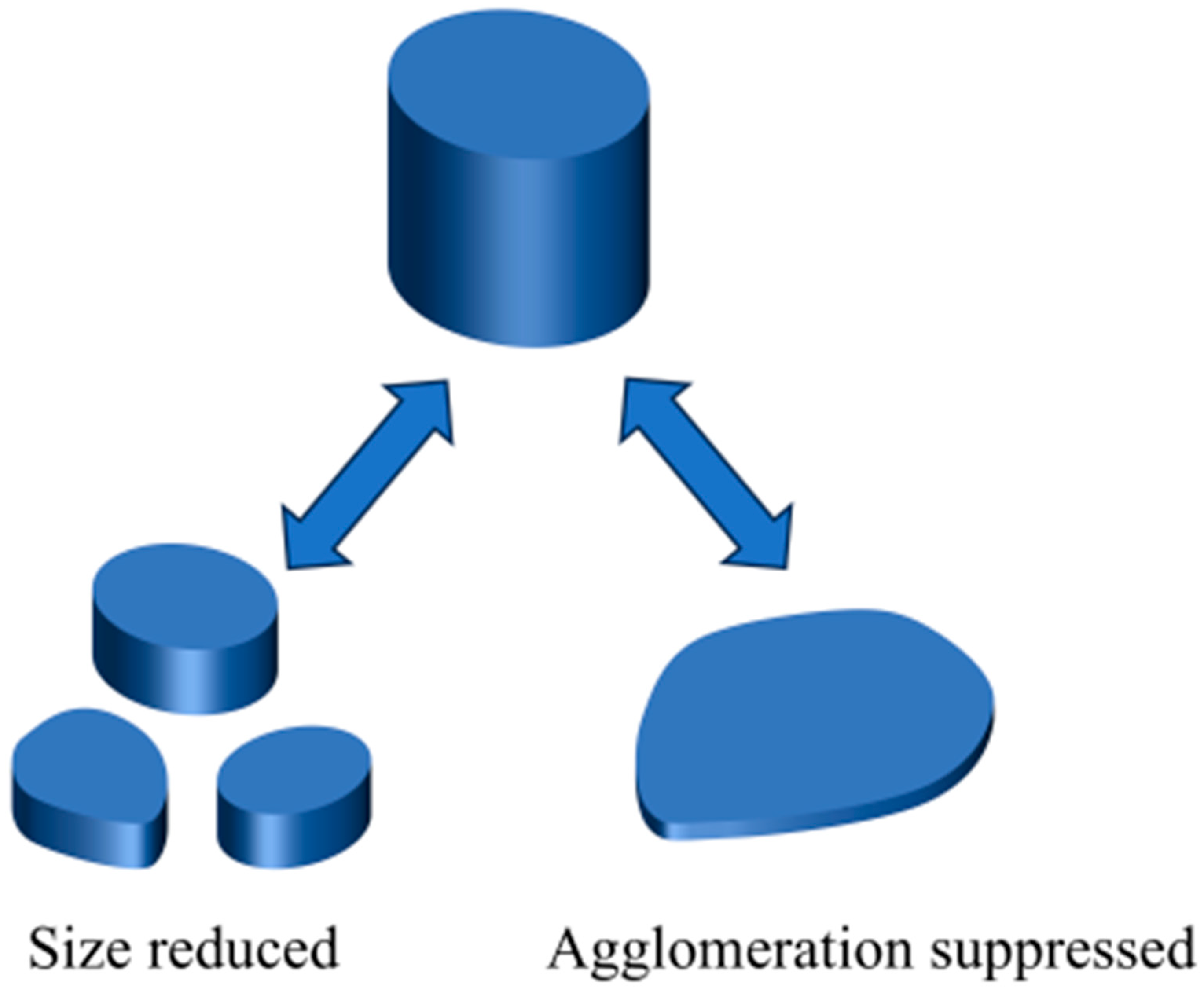
Figure 2. Sketch showing the difference between size reduction and low agglomeration.
Coatings 15 01370 g002
Figure 3. Sketch showing the mechanisms of currently used technologies for damping the LSPR of AgNPs.
Coatings 15 01370 g003
Figure 4. Effect of Ar plasma irradiation on the Ag layer. (a) Transmittance spectrum of TiO2/Ag/TiO2 sandwich structure changing with Ar plasma irradiation for 5 and 10 s. (b) The thickness of the Ag layer is changed from 11 to 20 nm while the thickness of TiO2 is fixed at 24 nm [27].
Coatings 15 01370 g004
Figure 5. Comparison of the effects of Ar and O plasma irradiation of the dielectric layer. (a) The SEM images of Ag layers of non-modified (NM) and Ar-plasma (ArP)- and O-plasma (OP)-modified electrodes’ evolution with increasing thickness of the Ag layer. Scale bar, 100 nm. (b) The structure models of NM and ArP- and OP-modified electrodes. (c) Rs of non-modified (NM) and Ar-plasma (ArP)- and O-plasma (OP)-modified electrodes’ evolution with the increasing thickness of the Ag layer. (df) The transmittance of the NM and ArP- and OP-modified evolution with the thickness of the Ag layer [39].
Coatings 15 01370 g005
Figure 6. Effect of Ar plasma irradiation. (a) UHR FE-SEM images of the evolving morphologies of the Ag layers deposited on SM-TiOx and NM-TiOx layers without ZnO overlayers, and SM is irradiated, and NM is unirradiated. (b) Peak-area ratios of OII/OI (OI, binding energy of 530.3–530.4 eV, from the O2− in TiO2 lattice; OII refers to oxygen-insufficient ions) are plotted as a function of the incident X-ray angle. (c) Island number density [40].
Coatings 15 01370 g006
Figure 7. Sketch showing the dynamics of O intermixing in the Ag-ZnO (O) matrix [43].
Coatings 15 01370 g007
Figure 8. (a) Cross-sectional HR-TEM micrographs of ZnO/Cu/ZnO (ZCZ) structures comprising non-modified (NM)- and ArP10-ZnO layers. The nominal Cu layer thickness is 0.5 nm for both specimens [46]. (b) Cross-sectional HR-TEM micrographs of AP-0W-TiOx/Cu/ZnO and AP-40W-TiOx/Cu/ZnO structures [47].
Coatings 15 01370 g008
Figure 9. Effects of oxygen additive during the whole Ag layer deposition. FE-SEM images showing morphological differences between (ac) Ag and (df) AgOx (O/Ag = 3.4 at%) layers deposited on 50 nm-thick ZnO films with different thicknesses: 6, 8, and 10 nm. (g) The structure models of ZnO/Ag/ZnO and ZnO/AgOx/ZnO. (h) The root-mean-square surface roughness of the Ag and AgOx layers according to AFM images. (i) The transmittances of the electrodes composed of Ag and AgOx (O/Ag = 3.4 at%) layers between 50 nm-thick ZnO films deposited on PET substrates, measured by excluding those of the PET substrates [48].
Coatings 15 01370 g009
Figure 10. Effect of inducing oxygen in the initial stage of deposition of the Ag layer. The surface morphologies of AZO/AgOx/Ag films prepared with different O2 flow ratios: (a) 0%; (b) 5%; (c) 10%; and (d) 15%. (e) The transmittance spectra of the AZO/AgOx/Ag/AZO composite films vary with the oxygen flow ratio during deposition of AgOx thin film [54].
Coatings 15 01370 g010
Figure 11. The effect of Ag2O sputtering powers on Rsh and T-ave of ZAAZ films. (a) Rsh, and (b) Tave [55].
Coatings 15 01370 g011
Figure 12. Effect of nitrogen introduction. Nitrogen additive-induced changes in morphology (ae). Highly magnified FE-SEM images showing morphologies of (a,b) Ag and (c,d) AgN NCs of two different thicknesses: ca. 0.7 and 1.5 nm, which evolved during the very early stages of Ag growth on 10 nm polycrystalline ZnO (0002) substrates. The scale bar is 20 nm [56]. (e) Sketch showing the morphology change due to nitrogen introduction. (f) Optical transmittance. (g) Sheet resistance and resistivity of the DAD multilayered films [44].
Coatings 15 01370 g012
Figure 13. Effect of nitrogen introduction. (a) Percolation threshold thickness (green squares, left axis) and film resistivity (t = 20 nm) (black squares, right axis). (b) Evolution of the Ag nanoparticle density with the fraction of N2 in the gas flow [57].
Coatings 15 01370 g013
Figure 14. The effect of Al doping. SEM images of (a) 9 nm pure Ag film, (b) 9 nm Al-doped Ag film. The insets in (a,b) are the corresponding AFM images. All films were deposited on fused silica substrates. The 9 nm pure Ag film has an RMS roughness of 10.8 nm, which is 12 times higher than that of the 9 nm Al-doped Ag film (0.86 nm). (c) The transmittance spectra of Al-doped Ag films and Al-doped Ag/ZnO films with different thicknesses. (d) The sheet resistivity of Al-doped Ag films, Al-doped Ag/ZnO films, and Al-doped Ag after annealing [58].
Coatings 15 01370 g014
Figure 15. Comparison of the effects of gas-assisted and pre-deposited seed layer on the optic-electric performance of TCE [67].
Coatings 15 01370 g015
Figure 16. Effect of the metal seed layer. (a) Effect of the thickness of the Ge seed layer on the roughness of the Ag layer. Ag thickness of 15 nm (red dot is data, blue dot line is guidance). The insets (Ⅰ,) show the contrast between a rough and a smooth surface for the SEM images without and with Ge (scale bar is 0.5 µm) [41]. (b) Comparison of the effect of Ni and Ge seed layers on the roughness difference in Ag thin films [68]. (c) Comparison of the effects of Cu, Si, and Ti seed layers on the roughness of the Ag layer. The scanning area was 10 μm × 10 μm. The 1 nm Cu/6 nm Ag sample has the best wettability and a flatter surface morphology, with a surface roughness smaller than 0.5 nm [73]. (d) Comparison of the effects of gas-assisted deposition and seed layer on the surface roughness [81]. (e) Comparative analysis of the effects of Ge seed layer and metal doping in reducing surface roughness [36].
Coatings 15 01370 g016
Figure 17. Effect of the Cu seed layer. (a) Thickness of the transmission of ZnS (50 nm)/Cu (x nm)/Ag (9 nm)/ZnS (50 nm) [76]. (b) Optical transmittance spectra. (c) Average transmittance in the range of 400–800 nm and sheet resistance of the MCAM samples with different thicknesses of Cu seed layer on the glass substrate [77].
Coatings 15 01370 g017
Figure 18. Effect of 0.5 nm Cu seed layer on the transmittance spectrum (a) and sheet resistance (b) of TCAT. t is the thickness of the Ag layer in the TAT and the TCAT thin films. x is the deposition rate of Ag. Dash lines in (b) denotes that the Rs is large and close to infinity when the thickness of Ag layer is smaller than 4 (black line) and 5 nm (red line) [24]. (c) Absorption spectra of the 1.0 nm CuNPs, 1.0 nm AgNPs, 1.0 nm CuNPs-1.0 nm AgNPs, and 1.0 nm AgNPs-1.0 nm CuNPs. (df) Sketch illustration of the improvement of wettability of AgNPs by Cu seed layer. (d) and (e) CuNPs and AgNPs grown on glass substrates respectively. (f) CuNP grown on AgNPs, indicating that the AgNP on CuNPs are flatter than AgNPs on glass [78].
Coatings 15 01370 g018
Figure 19. Effect of Cu seed layer on the DAD transparent electrode performance. (a) Optical transmittance spectra of the AZO/Cu/Ag (5 nm)/AZO multilayer transparent electrodes with various thicknesses of Cu seed layer. (b,c) Sheet resistances and FOMs of the AZO/Cu/Ag (5 nm)/AZO multilayer transparent electrodes as a function of Cu seed layer thickness [79].
Coatings 15 01370 g019
Figure 20. Comparison of the difference in optoelectronic performance caused by Ge and Ti seed layers. (a) Transmittance, (b) reflectance, and (c) absorbance of SiOx/Ge/Ag/SiOx fabricated on glass with a 6.0 nm-thick Ag layer using different Ge interlayer thicknesses. (d) Variation in the sheet resistance of the Ag layers compared with those of the 6.0 nm-thick Ag (Al) and Ag (Cu) layers in the multilayer configuration (inset). The thicknesses of the bottom and top SiOx layers are 5 and 25 nm, respectively [36]. (e) Transmittance and (f) reflectance spectra of AZO/Ti/Ag/AZO (ATAxA, x denotes the thickness of Ag (nm)) [71]. Optical properties of AZO/Ti/Ag/AZO of films as a function of Ti power. (g) Transmittance spectra; (h) Absorption spectra [72].
Coatings 15 01370 g020
Figure 21. (a) Transmittance over 100% is achieved. The transmittance of ZTO/Ag/ZTO (green dashed line) was higher than that of PC substrates (green solid line) in the range of 500–700 nm, indicating the transmittance of ZTO/Ag/ZTO exceeded 100% [90]. (b) Effect of dielectric layer materials on the transmittance and reflectance of TiO2/Ag/TiO2 and TNO/Ag/TNO (Nb-doped TiO2) [92].
Coatings 15 01370 g021
Table 1. The parameters of Ag layer doping and applications in DAD.
T/Tav (%)Rs (Ω/sq)FOM Value (×10−3 Ω−1)tCT (nm)Surface RoughnessRef.
Ag:Al8014.2  0.82[59]
Ta2O5/7 nm Ag:Al/ZnO96.0 at 550 nm23.128.78  [60]
TiO2/Ag:Al/TiO2/MgF292.42022.68  [38]
TiO2/10 nm Ag:Cr/TiO294.2 at 550 nm 57.15  [61]
6 nm Ag:Cu7614.1 60.19[62]
Ag: Ni8018.92 70.57[63]
AZO/6 nm Ag:SnOx/AZO8810.825.796 [65]
Zn:SnOx/10 nm ATC/Zn:SnOx897.841.586 [64]
ZnO/Cu:Ag/ZnO89    [66]
Table 2. The pros and cons of different approaches.
MethodMain AdvantagesMain Drawbacks
Plasma irradiationReducing the size of AgNPs by Ar plasma or increasing the nucleation density by producing defects on the dielectric surface, or reducing the interface energy between the Ag layer and the dielectric layer by oxygen plasma; high efficiency damping LSPR, and high FOM.
Improved interfacial contact.
Equipment/parameters are more complex (power, atmosphere, duration, etc.)
Gas-assisted depositionReducing the interface energy, or increasing nucleation density to damp LSPR; reduced tCTChallenging in precise control of gas flow rate/partial pressure.
Metal dopingIncreasing the nucleation density to damp LSPR significantly reduced tCT and roughness.Absorbance of doped metals leading to degraded transmittance.
Seed layerIncreasing the nucleation density for damping LSPR effectively reduced tCT and roughness.Absorbance or reflectance of the metal seed layer itself leading to reduced transmittance.
Disclaimer/Publisher’s Note: The statements, opinions and data contained in all publications are solely those of the individual author(s) and contributor(s) and not of MDPI and/or the editor(s). MDPI and/or the editor(s) disclaim responsibility for any injury to people or property resulting from any ideas, methods, instructions or products referred to in the content.