Article

Theoretical Design and Experimental Study of a Piezoelectric Energy Harvesting System for Self-Powered Ski Boots

1
School of Mechanical and Electrical Engineering, Jilin University of Chemical Technology, Jilin 132022, China
2
Academic Affairs Office, Jilin University of Chemical Technology, Jilin 132022, China
3
School of Mechanical and Electrical Engineering, Henan University of Technology, Zhengzhou 450001, China
4
School of Automotive and Mechanical Engineering, Liaoning Institute of Science and Engineering, Jinzhou 121013, China
*
Author to whom correspondence should be addressed.
Coatings 2025, 15(11), 1288; https://doi.org/10.3390/coatings15111288
Submission received: 13 October 2025 / Revised: 28 October 2025 / Accepted: 30 October 2025 / Published: 4 November 2025

Abstract

At present, energy harvesting technologies are gradually replacing batteries and have become a research hotspot as power sources for low-power components in wearable electronic devices. To collect and utilize the energy generated by skiers during the process of pushing against the skis, a piezoelectric energy harvesting system (PEHS) for self-powered ski boots was proposed and designed to supply power for low-power wearable devices. The output voltage of the PEHS was modeled and simulated using the finite element method, and the causes of the simulation results were analyzed. An energy harvesting experiment of the prototype was conducted under loading conditions using a universal testing machine. Under a uniform sinusoidal load of 800 N at 1 Hz, the prototype of the PEHS for self-powered ski boots achieved a maximum output power of 57.44 mW with an optimal matching load resistance of 404 kΩ. A skiing tester wearing the self-powered ski boots conducted real-motion experiments, performing three different actions: (1) alternating single-foot stepping for propulsion, (2) alternating left and right ski edge stepping for propulsion, and (3) alternating forefoot and heel stepping for propulsion. The instantaneous peak voltages measured in these tests were statistically analyzed, and the corresponding peak power values were calculated through theoretical computation to be 6.48 ± 0.27 mW, 4.47 ± 0.21 mW, and 13.21 ± 0.48 mW for the three actions, respectively (expressed with a 95% confidence interval).

1. Introduction

With the rapid development of wearable electronic products, the demand for wearable and portable power sources is growing significantly. At present, there have been numerous studies on rechargeable shoes, and some mature technologies have already been commercialized [1,2,3]. After charging, the lithium batteries embedded in such shoes can supply power to low-power devices in smart wearables [4,5,6]. However, since the capacity of lithium batteries is positively correlated with their volume and weight, the limited space inside shoes can only accommodate small-capacity batteries, making it difficult to support high-power devices for long durations. Moreover, rechargeable shoes may require daily or every-other-day charging, which runs counter to the “maintenance-free” expectation of wearable electronics. If shoes are subjected to strong compression, bending, or even puncturing during daily use, lithium batteries may short-circuit, overheat, or catch fire. In addition, the inclusion of batteries and circuit modules increases shoe weight, reducing wearer comfort and flexibility. Furthermore, customized lithium batteries, waterproof encapsulation, and safety protection designs substantially raise product costs. Meanwhile, the significantly reduced endurance performance of lithium batteries at low temperatures, along with the challenges of recycling and environmental issues associated with discarded batteries, has long been a concern. To address the above challenges, energy harvesting technologies such as miniature triboelectric generators, micro photovoltaic cells, and piezoelectric energy harvesters have attracted widespread attention as potential power sources for wearable electronic devices, and several related studies have already achieved successful results [7,8].
Piezoelectric materials are among the advanced functional materials developed and gradually refined in modern times [9,10,11]. They exhibit fast response to subtle vibrations, making them well-suited for capturing instantaneous mechanical energy. By utilizing the piezoelectric effect, mechanical energy can be directly converted into electrical energy without the need for heat engines or intermediate processes, thereby effectively reducing energy loss. Within a given volume or weight, they can output relatively high electrical power, which is particularly advantageous for miniaturized and low-power devices. Compared with electromagnetic energy harvesting, piezoelectric materials do not require complex components such as coils or magnets. Their structure is compact, easy to integrate, and free from both the generation and reception of magnetic interference, ensuring excellent electrical response and simplifying the realization of automation and intelligent control. In summary, piezoelectric materials can form self-powered systems to supply energy for low-power devices and maintenance-free wearable electronics, showing promising application prospects [12,13,14,15,16,17].
Asano S. et al. developed an energy harvester employing a parallel-link mechanism combined with six sets of multilayer piezoelectric transducers. This structure enabled more efficient energy conversion compared with conventional harvesters in terms of maximum power output, wearing comfort, durability, and adaptability to six-degree-of-freedom inputs. The prototype of the parallel-link piezoelectric energy harvester was able to generate 1.29 mW of electrical power under the load of human body weight [18].
Yin Z. et al. proposed a shoe-mounted piezoelectric energy harvester (PEH) designed to collect energy from human walking. The device employs a frequency up-conversion mechanism, realized through the impact between a ratchet and a piezoelectric beam during the gait cycle. They fabricated a PEH prototype and tested its performance under different walking frequencies. As the step frequency increased from 1.5 Hz to 4 Hz, during the ascending phase, the peak output power and average output power increased from 9.17 mW and 0.11 mW to 13.88 mW and 0.98 mW, respectively. During the descending phase, the peak output power fluctuated slightly around 8 mW, while the average output power increased marginally from 0.12 mW to 0.18 mW [19].
Vitorino J. et al. conducted tests to measure the energy harvested by multiple sets of piezoelectric ceramic materials embedded in the soles of soldiers’ boots. They explored different materials and arrangements to maximize power output and ultimately developed a prototype device. The prototype was able to harvest an average of 875 microjoules (μJ) of energy per step. At a walking pace of 40 steps per minute for one hour, it could generate 2.1 joules of energy—sufficient to power a device operating at 3.3 V and consuming 10 mA for about one minute [20].
In addition, Gesse David Samuel et al. proposed a hybrid renewable energy generation model that utilizes two energy sources—footstep energy harvesting systems and photovoltaic (PV) or solar panels—to generate electricity. In this model, the piezoelectric transducer converts the mechanical vibrations produced by footstep pressure into electrical energy, while the solar panel converts solar energy into electricity [21]. C. Spampinato et al. proposed a novel fabrication method for a photoactive layer used in semitransparent perovskite solar cells (ST-PSC). Looking forward, this layer structure can be applied to perovskite solar cells, and its feasibility has been verified through simulations [22].
In summary, the application of piezoelectric energy harvesters in footwear is still very limited. Most of them rely on mechanical structures to amplify displacement or driving force, which is then applied to the piezoelectric elements to convert mechanical energy into electrical energy. However, such approaches reduce the available space inside the shoe, compromising portability and comfort—key requirements for wearable devices—making this method more suitable for use in fixed locations rather than in wearable applications.
At present, research on the application of piezoelectric energy harvesting in skiing remains largely unexplored. During skiing, variations in human biomechanical behavior can generate considerable amounts of energy. To capture and utilize this energy for powering low-power wearable devices—such as posture sensors and locators used in skiing, this paper presents the design of a piezoelectric energy harvesting system (PEHS) for self-powered ski boots. By collecting the mechanical energy produced by the body, ski slope terrain variations and ski boots during movement, and converting it into electrical energy through piezoelectric materials, experimental studies were conducted to validate its feasibility.

2. Structural Design and Working Principle

2.1. Available Energy in Skiing

When engaging in skiing, athletes need to lean their bodies and exert force by pressing against the ski boots, making full use of the ski edges to scrape snow. The resulting friction drives the skis forward and enables turning maneuvers. Even when skiers glide downhill naturally under gravity, they must perform these actions to control posture and turning. During this process, the repetitive stepping forces of the skier’s body on the ski boots, as well as the mechanical energy generated by the vibrations of the shoes against the uneven snow, can be captured by a PEHS embedded in the ski boots. Through the piezoelectric effect, this mechanical energy can be converted into electrical energy to power low-power wearable devices.

2.2. Structural Design

The structural design of the PEHS for self-powered ski boots in this study is shown in Figure 1. The fixed substrate is mounted to the sole using bolts. Eight stepped grooves are arranged on it to position, constrain, and support the piezoelectric oscillator assemblies (each composed of a piezoelectric ceramic plate, metal Substrate, and elastic support bonded together). The energy harvesting module is also bolted into a recess on the upper surface of the substrate. Two upper pressure plates, placed at the front and rear, are arranged above the fixed substrate. Limited by surrounding slots, they are capable of vertical displacement. The top layer is equipped with an insole, which is placed over the upper pressure plate to support the skier’s foot. The PEHS assembled with bolts, is mounted at the inner bottom of the ski boot shell, which is secured to the skis through the ski bindings, as shown in Figure 2.

2.3. Working Principle

When the skier leans and exerts force to step down, the piezoelectric oscillator assemblies in the ski boots—composed of the piezoelectric ceramic plate, metal substrate, and elastic support bonded together—are subjected to force and undergo bending deformation. Through the piezoelectric effect, the mechanical energy is converted into electric charge, which is then rectified, regulated, and stored by the energy harvesting module to supply power for low-power wearable devices.

3. Modeling and Simulation for the PEHS

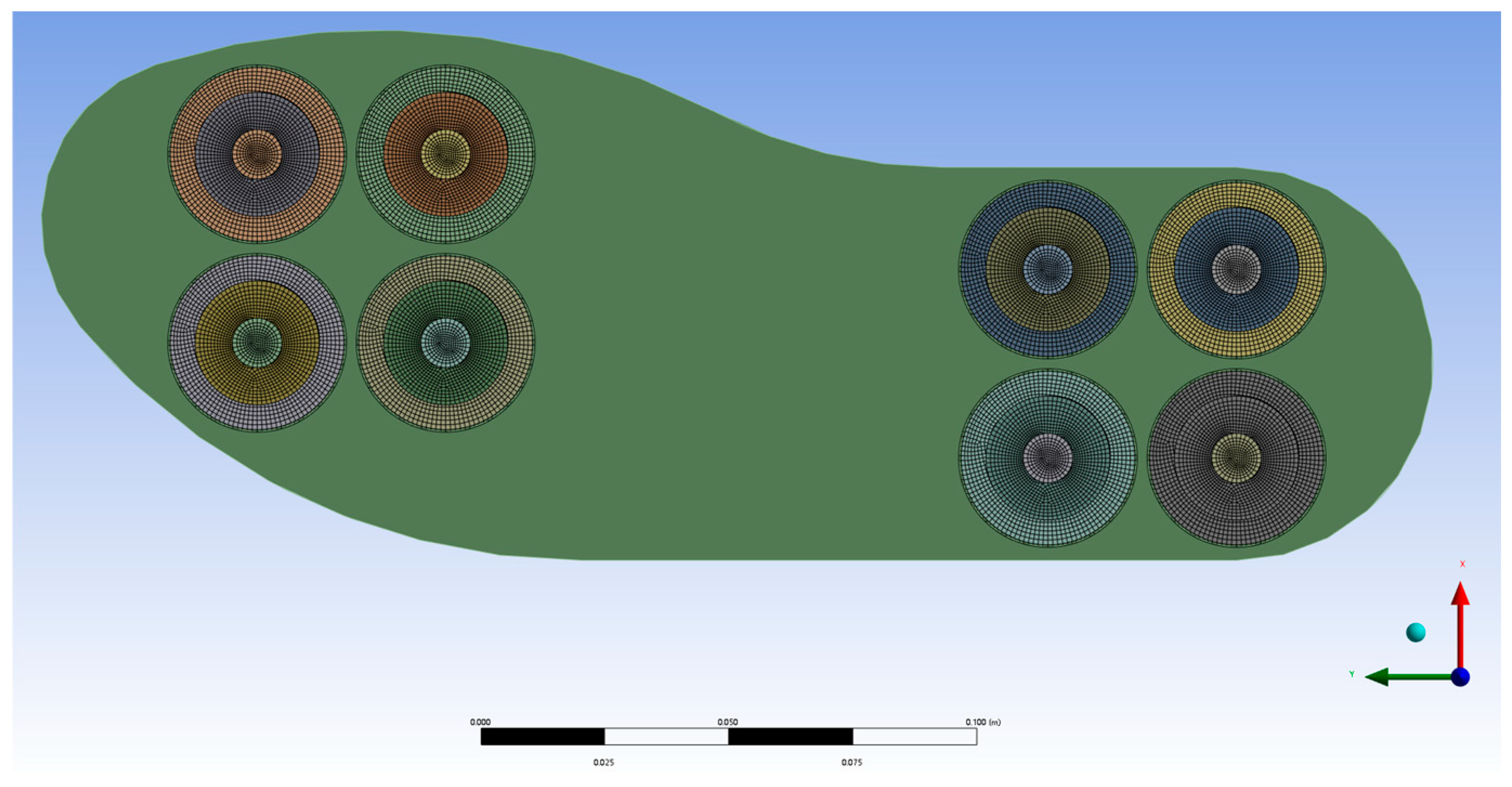
The finite element analysis software ANSYS 2021 R1 was used to model the PEHS for the self-powered ski boots in this study. The parameters are shown in Table 1, with a mesh size of 1 mm. The established finite element model is shown in Figure 3.

3.1. Static Strength Simulation Analysis for the PEHS

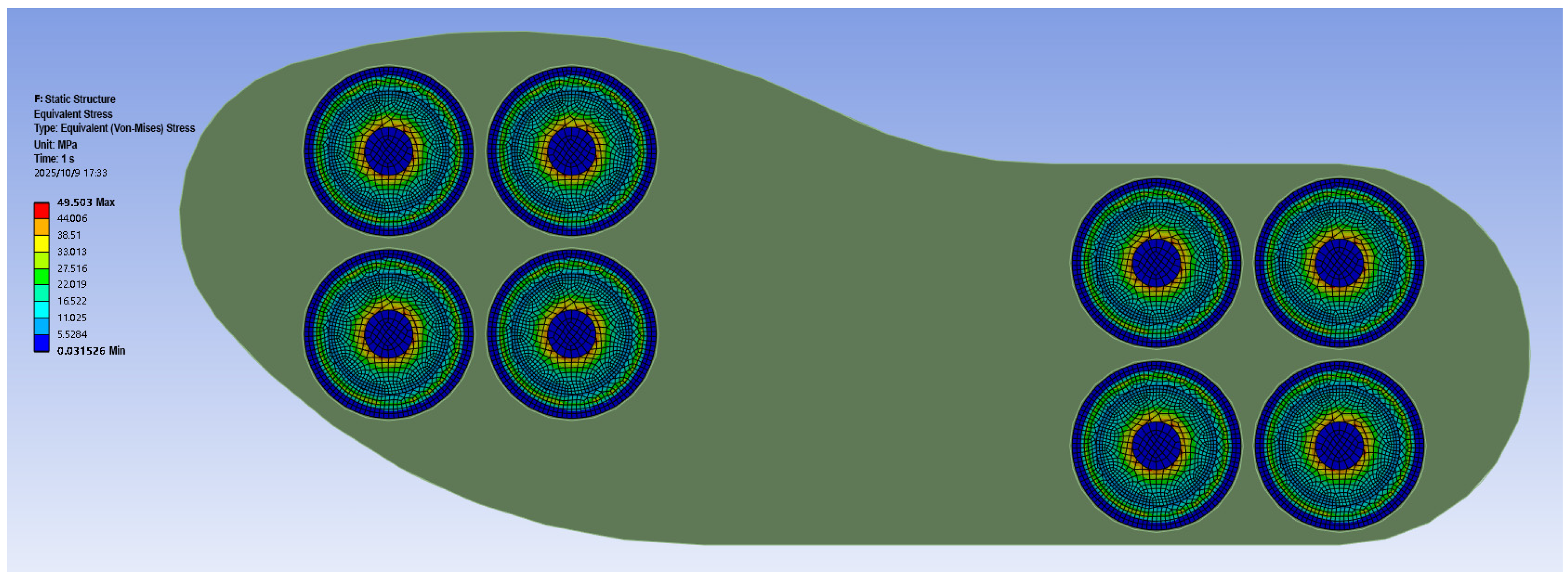
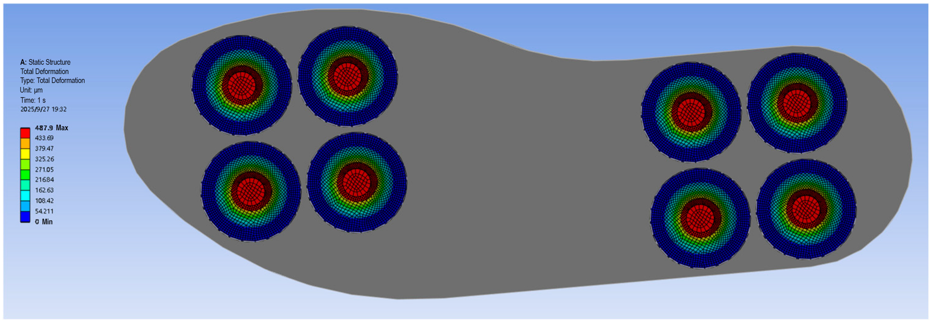
A uniform Z-direction load of 800 N was applied to the insole section of the finite element model of the PEHS for self-powered ski boots. The fixed substrate was fully constrained in all six degrees of freedom, while the upper pressure plates were constrained in five degrees of freedom: translation in the X and Y directions and rotation about the X, Y, and Z axes. The solution shows that the stress distribution of the piezoelectric ceramic plate in the loaded piezoelectric actuator assembly is ring-shaped, meaning that points at the same radius experience the same stress, which decreases with increasing radius. The maximum stress on the piezoelectric ceramic plate under load is 49.503 MPa, and the maximum stress on the metal substrate is 44.967 MPa, as shown in Figure 4 and Figure 5, both meeting the design strength requirements. The deformation at points with the same radius on the piezoelectric ceramic plate is equal and decreases with increasing radius, with the maximum deformation occurring at the center of the plate, measuring 0.52178 mm.

3.2. Simulation Analysis of the Voltage Generated by the PEHS

A structural–electric-field coupled analysis was performed on the PEHS for self-powered ski boots to simulate the harvested voltage under loading. The relative permittivities ε1, ε2, and ε3 (dimensionless), the piezoelectric constants e1, e2, and e3 (C/m2), and the elastic stiffness matrices c1, c2, and c3 (N/m2) of the piezoelectric ceramic plates made of PZT-4, PZT-5A, and PZT-5H were set as follows:
ε 1 = 762 762 663   e 1 = 0 0 0 0 0 12.295 0 0 0 0 12.295 0 5.350 5.350 15.780 0 0 0
c 1 = 12.035 7.517 7.509 0 0 0 0 12.035 7.509 0 0 0 0 0 11.087 0 0 0 0 0 0 2.258 0 0 0 0 0 0 2.105 0 0 0 0 0 0 2.105 × 10 10
ε 2 = 916 916 830   e 2 = 0 0 0 0 0 12.3 0 0 0 0 12.3 0 5.4 5.4 15.8 0 0 0
c 2 = 12.1 7.54 7.52 0 0 0 0 12.1 7.52 0 0 0 0 0 11.1 0 0 0 0 0 0 2.11 0 0 0 0 0 0 2.11 0 0 0 0 0 0 2.26 × 10 10
ε 3 = 1100 1100 827   e 3 = 0 0 0 0 0 10.5 0 0 0 0 10.5 0 4.1 4.1 14.1 0 0 0
c 3 = 12.0 7.50 7.51 0 0 0 0 12.0 7.51 0 0 0 0 0 11.1 0 0 0 0 0 0 2.11 0 0 0 0 0 0 2.11 0 0 0 0 0 0 2.26 × 10 10
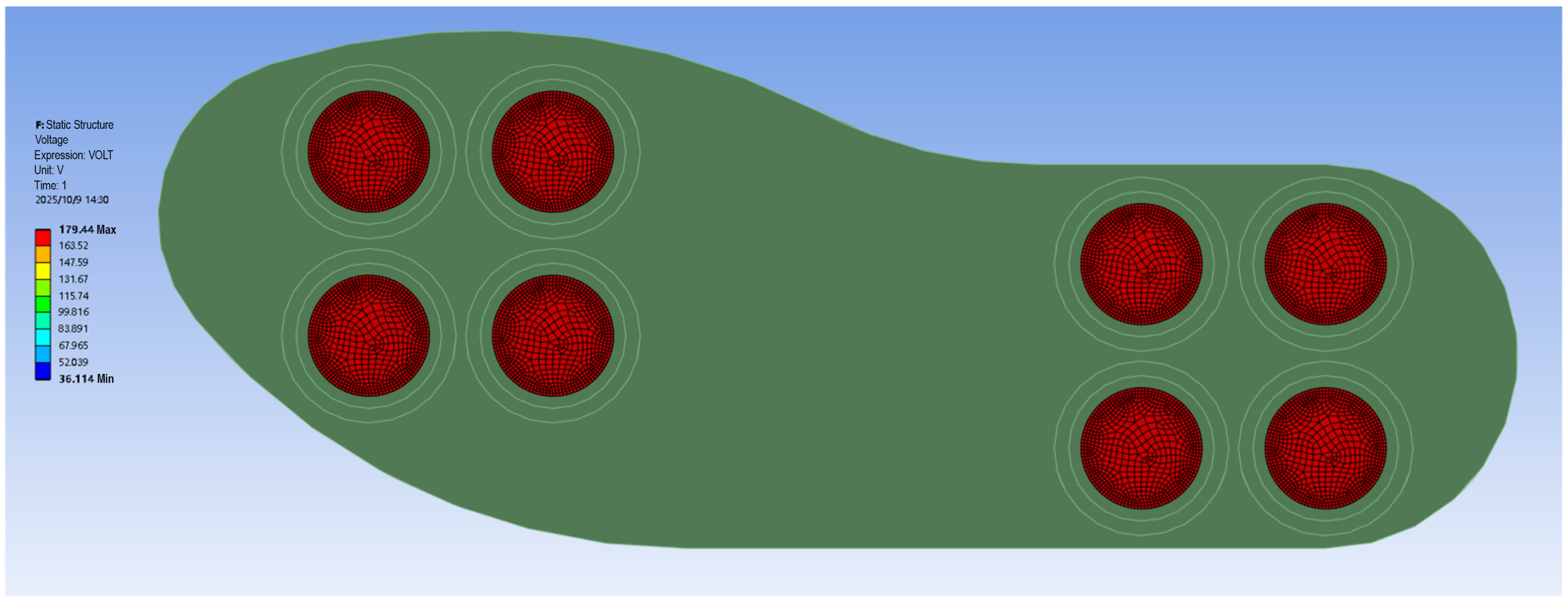
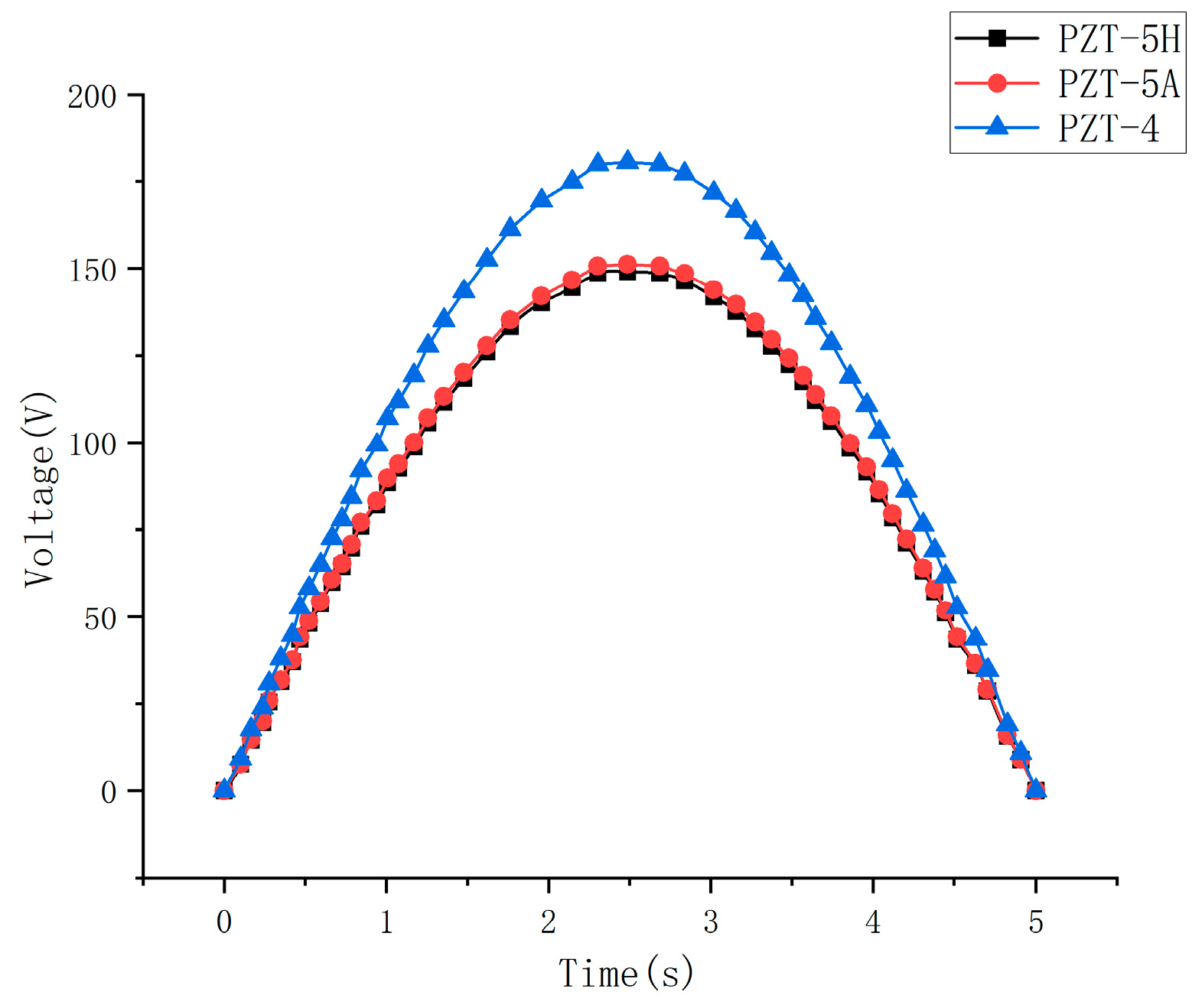
Figure 6 shows the voltage cloud diagrams of each piezoelectric ceramic plate under a loading condition of 800 × sin [(π/5) × time] N applied to the insole. Piezoelectric actuators were constructed using piezoelectric ceramic plates made of three different materials—PZT-5H, PZT-5A, and PZT-4—and their corresponding voltage curves were obtained. The instantaneous open-circuit voltage peaks were 149.1 V, 151.3 V, and 180.4 V, respectively, as shown in Figure 7. As illustrated, when a periodic sinusoidal load is applied to the piezoelectric ceramic plate, a cyclic mechanical stress is generated in the model, inducing a periodic variation in electric displacement across the piezoelectric ceramic plate. This results in a time-varying potential difference between the electrodes, corresponding to the alternating voltage output observed in the simulation. Since the applied load varies sinusoidally with time, both the stress and voltage of the piezoelectric ceramic plate exhibit sinusoidal variations with the same frequency.
Although the above simulation results indicate that the piezoelectric vibrator made of PZT-4 material exhibits the highest output voltage peak, we chose to use PZT-5H material for prototype fabrication and experimental testing. This is because PZT-5H belongs to the category of soft piezoelectric ceramics, which is particularly important for energy harvesting under the low-frequency and small-amplitude loading conditions used in this study. Furthermore, PZT-5H possesses better polarization stability and electrical sensitivity, ensuring stable output performance during repeated loading. It is also easier to polarize and shape, making it well suited for thin-sheet and multilayer structural fabrication.

4. Experimental Setup and Results Analysis

4.1. Energy-Harvesting Test of the Prototype Under Loading by a Universal Testing Machine

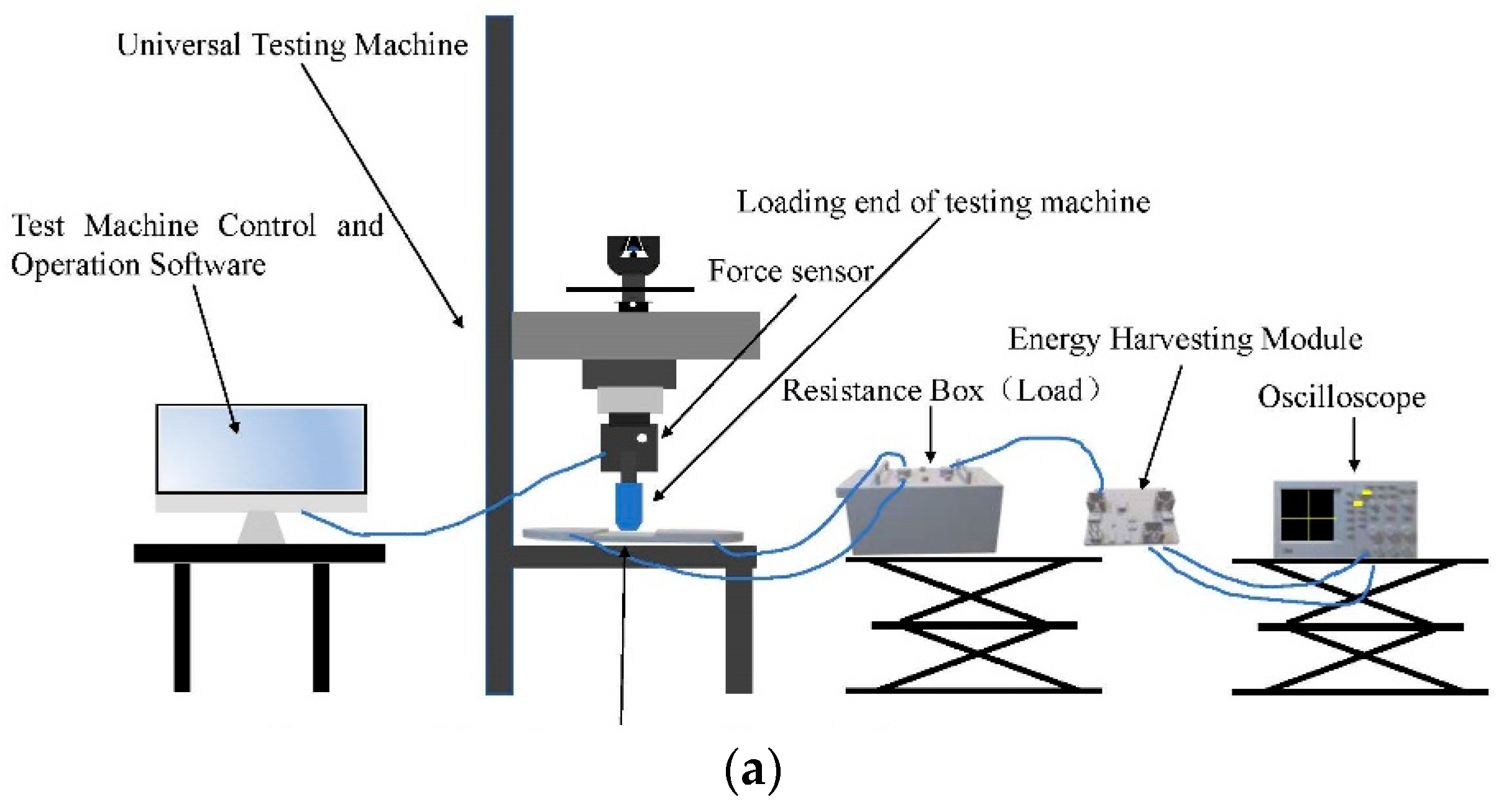
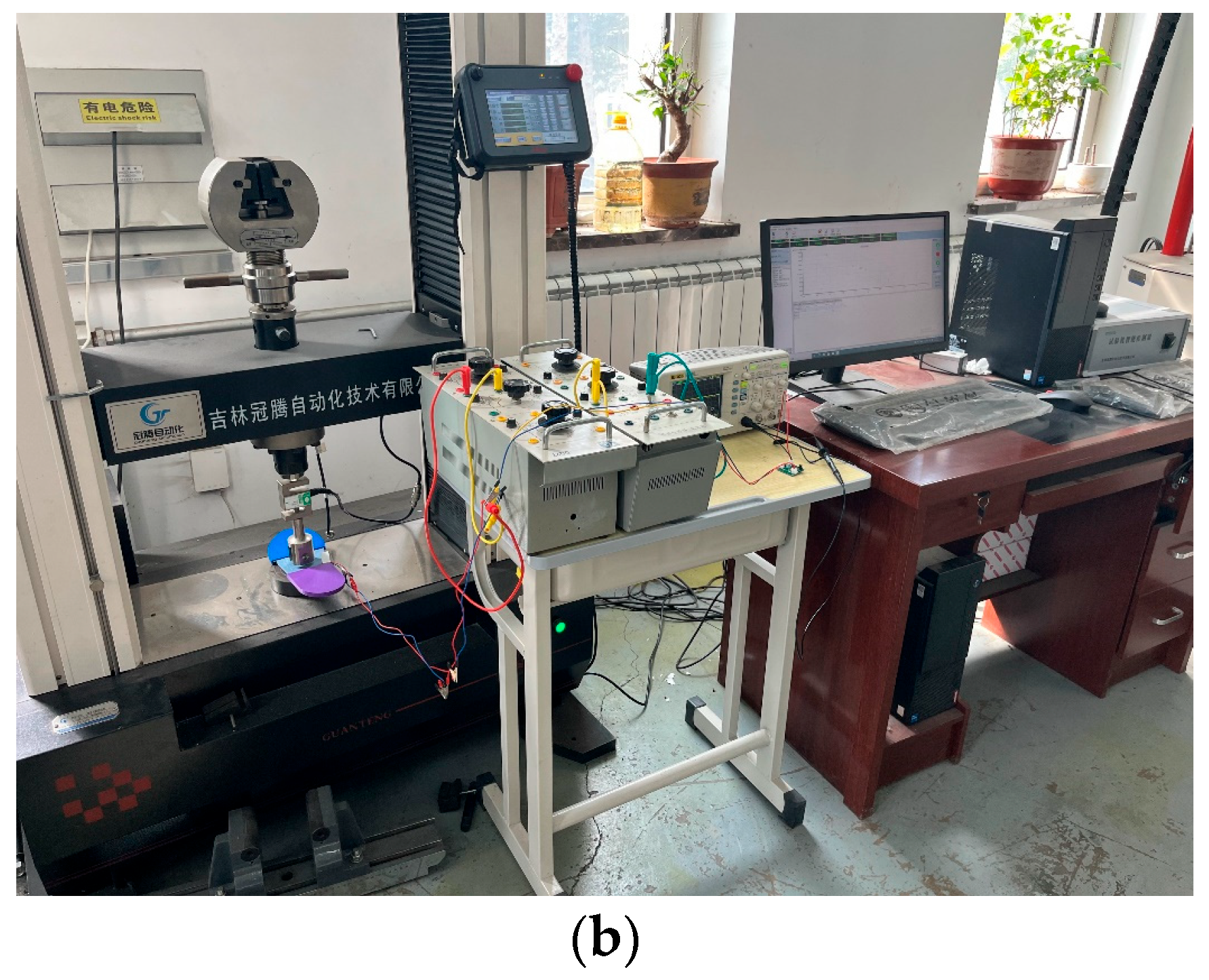
To evaluate the power generation capability of the PEHS prototype for self-powered ski boots under a specific loading frequency, a test platform was established, as shown in Figure 8. The Test Machine Control and Operation Software was configured, and based on the readings from the Force sensor, the universal testing machine (Guanteng, Changchun, China) was operated so that its circular loading end applied a downward load along the vertical Z-axis. A sinusoidal load of 800 N at 1 Hz was applied to the center of the upper pressure plate. A Resistance Box was used to match the load resistance of the PEHS prototype.
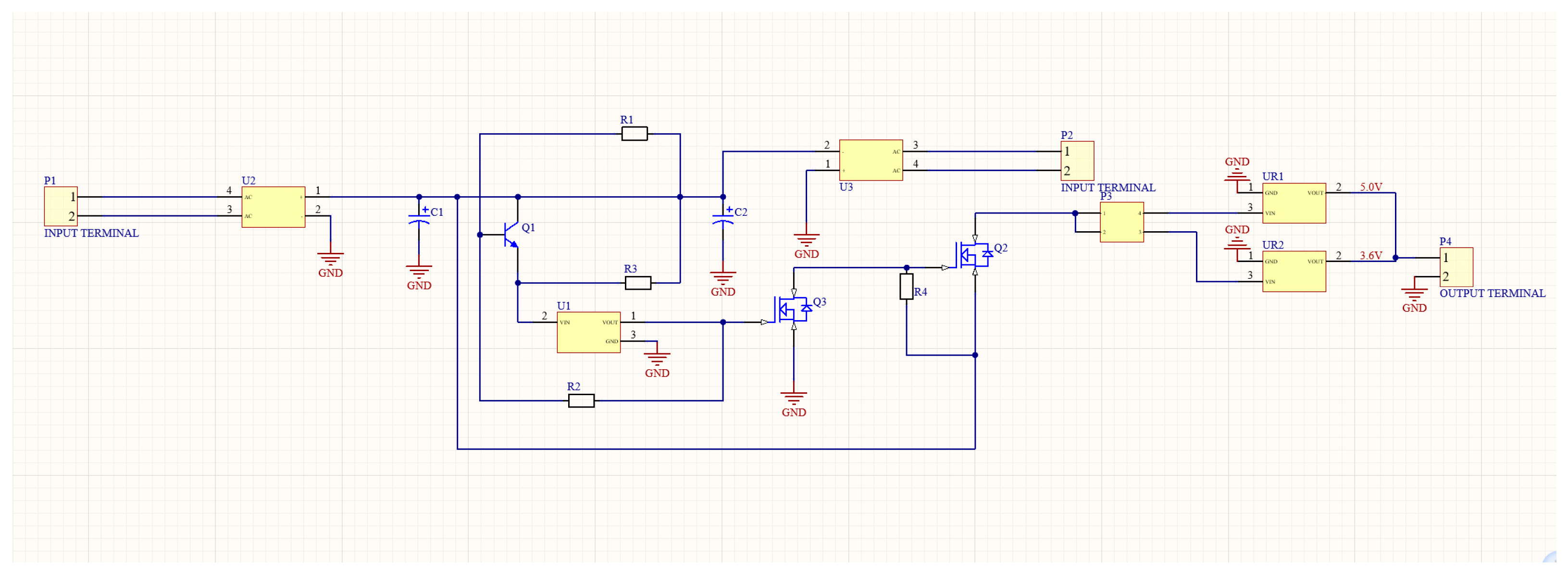
Meanwhile, an Energy Harvesting Module was designed in this study to rectify, regulate, and store the weak alternating current generated by the PEHS, providing a stable DC output voltage. The circuit schematic is shown in Figure 9. An Oscilloscope was employed to measure the terminal voltage generated by the PEHS prototype.
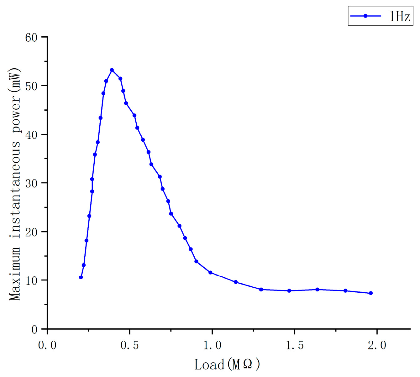
The experimental results are shown in Figure 10. As the load resistance increases, the instantaneous maximum power rises rapidly, and when the load resistance reaches 404 kΩ, based on the piezoelectric energy harvesting calculation method under the plate-shell theory [23], the maximum output power P of the prototype (under the conditions of 1 Hz and 800 N force) is calculated as follows:
P = U 2 C P 2 T = 57.44   m W
where U is the open-circuit voltage generated by the piezoelectric vibrator under load, CP is the free capacitance of the piezoelectric vibrator, and T is the time.
As the load resistance continues to increase, the voltage across the load rises, while the maximum output power of the prototype gradually decreases until it approaches zero.
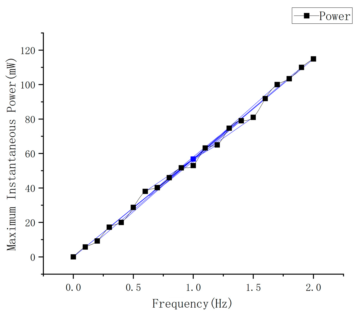
During skiing, the frequency of the skier’s leg exertion and stepping on the ski varies with body movement and gliding state. To evaluate the energy harvesting performance of the PEHS at different frequencies of human stepping, a uniform load of 800 N was applied by the universal testing machine at frequencies ranging from 0.1 Hz to 2 Hz (under the optimal matching impedance for each frequency). The relationship between the instantaneous maximum power generated by the PEHS prototype for self-powered ski boots and the loading frequency is shown in Figure 11. As the frequency increases, the instantaneous maximum power also increases. In other words, within the frequency range of 0–2 Hz, the more frequently a person steps on the ski boots, the greater the instantaneous maximum power generated by the PEHS—showing an almost proportional relationship.

4.2. Energy-Harvesting Test with the Prototype Worn by a Skier

When skiing, the skier exerts force on the skis through stepping motions, which mainly include three types of movements:
Action 1: alternating single foot stepping for propulsion;
Action 2: alternating left and right ski edge stepping for propulsion;
Action 3: alternating forefoot and heel stepping for propulsion;
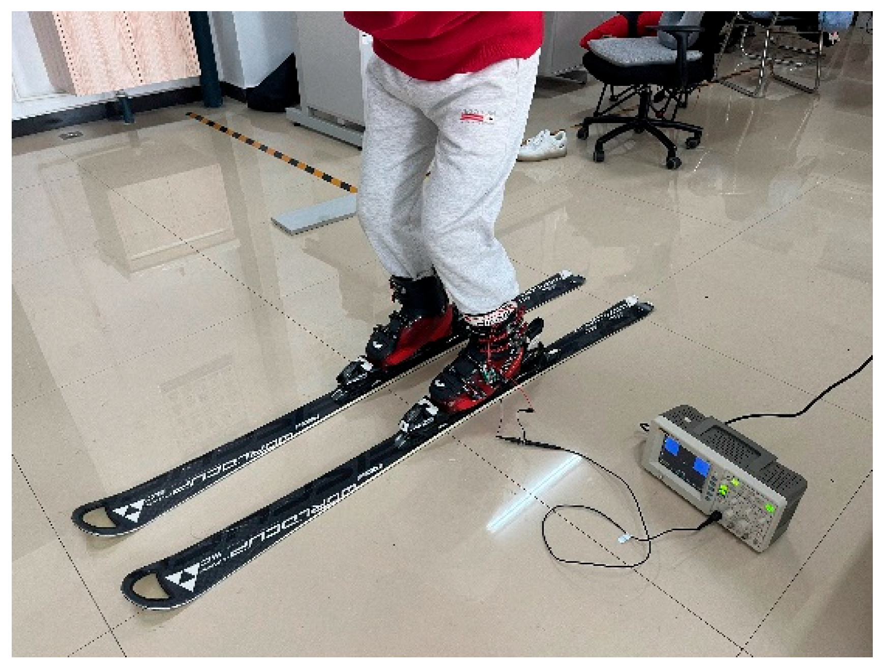
To evaluate the energy harvesting performance of the PEHS prototype for self-powered ski boots under these three different stepping motions, skiing tests were conducted with a tester wearing the prototype. The tester weighed 80 kg and wore the self-powered ski boots developed in this study. The tester performed Actions 1, 2, and 3 while stepping on the skis, as shown in Figure 12. To ensure the accuracy of the experiment, each measurement was conducted for 30 s using a mobile phone timer. Each measurement group included 30 complete cycles of a single action (1, 2, or 3), and each action was tested for 30 groups.
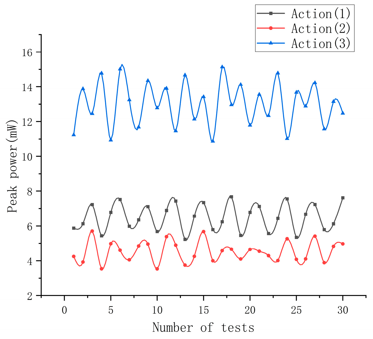
The 2700 peak voltage data points obtained from the tests—corresponding to 30 trials × 30 groups × 3 actions—were statistically analyzed, and the peak power was calculated using Equation (1). The results are shown in Figure 13. As shown in the figure, the energy harvesting performance differs significantly among the three actions. The alternating left and right ski edge stepping for propulsion (Action 2) exhibited the lowest peak output power of 4.47 ± 0.21 mW, while the alternating single-foot stepping for propulsion (Action 1) produced a peak output power of 6.48 ± 0.27 mW. The alternating forefoot and heel stepping for propulsion (Action 3) achieved the highest peak output power, reaching 13.21 ± 0.48 mW. All the above data are expressed with a 95% confidence interval.

5. Conclusions

This paper presents the structural and circuit design of a piezoelectric energy-harvesting system (PEHS) for self-powered ski boots. The output voltage was analyzed through finite element simulation, and a prototype was fabricated and experimentally tested. The following conclusions were obtained:
(1)
A finite element static strength simulation analysis was conducted for the structure of the PEHS for self-powered ski boots, and the design meets the strength requirements. The output voltages of the PEHS made with three different piezoelectric ceramic materials—PZT-5H, PZT-5A, and PZT-4—were simulated, yielding instantaneous open-circuit peak voltages of 149.1 V, 151.3 V, and 180.4 V, respectively. The causes of these results were analyzed.
(2)
A piezoelectric energy-harvesting test of the prototype was conducted under loading by a universal testing machine. Under a uniformly distributed load of 800 N at a frequency of 1 Hz, the maximum output power of the PEHS prototype for self-powered ski boots reached 57.44 mW, with a matching load resistance of 404 kΩ. Under uniformly distributed loads of 800 N at frequencies ranging from 0.1 to 2 Hz, the instantaneous maximum power generated by the prototype (at the optimal matching impedance for each frequency) exhibited an approximately linear relationship with the loading frequency.
(3)
A piezoelectric energy-harvesting test was conducted with the prototype worn by a skier. The tester weighed 80 kg and wore the self-powered ski boots developed in this study. At a motion frequency of 1 Hz, three different skiing actions were performed:
Action 1: alternating single-foot stepping for propulsion;
Action 2: alternating left and right ski edge stepping for propulsion;
Action 3: alternating forefoot and heel stepping for propulsion;
The generated electrical power for these actions were 6.48 ± 0.27 mW, 4.47 ± 0.21 mW, and 13.21 ± 0.48 mW, respectively.
The simulation and experimental results demonstrate that the PEHS for self-powered ski boots proposed and designed in this study can effectively convert the mechanical energy generated during skiing into electrical energy under low-frequency and small-amplitude loading conditions. This provides a feasible solution for powering low-power devices such as posture sensors, GPS trackers, and wireless communication modules integrated into smart sports equipment. In addition, the system structure exhibits good mechanical reliability under repeated cyclic loading, laying the foundation for the development of self-sustaining intelligent wearable systems.
However, this study still has some limitations. All experiments were conducted under controlled laboratory conditions and not in real skiing environments. In actual ski fields, complex and variable factors such as slope gradient, snow surface roughness, and temperature fluctuations may significantly influence the mechanical loading characteristics and output performance of the PEHS. Therefore, in future work, we plan to perform on-snow field tests and integrate the system with real wearable devices to comprehensively evaluate its practicality, durability, and long-term stability.

Author Contributions

Conceptualization, M.J.; methodology, M.J., L.C., D.J., Z.Q. and S.Z.; software, L.C. and Z.S.; validation, M.J., L.C. and Z.S.; formal analysis, M.J., L.C. and Z.S.; investigation, M.J.,L.C. and Z.S.; resources, M.J. and D.J.; data curation, L.C.; writing—original draft preparation, M.J. and L.C.; writing—review and editing, M.J. and S.Z.; visualization, L.C., Z.S., F.Z., Y.Z., Z.L. and J.C.; supervision, M.J.; project administration, M.J. and D.J.; funding acquisition, M.J. and D.J. All authors have read and agreed to the published version of the manuscript.

Funding

This research was funded by Jilin Provincial Department of Education of China (JJKH20240306KJ).

Institutional Review Board Statement

Not applicable.

Informed Consent Statement

Not applicable.

Data Availability Statement

The original contributions presented in the study are included in the article, further inquiries can be directed to the corresponding author.

Conflicts of Interest

The authors declare no conflicts of interest.

References

  1. Chen, Z.; Li, J.; Song, W.; Lu, Y.; Cao, B. Smart Wireless Charging Heating Insoles: Improving Body Thermal Comfort of Young Males in an Extremely Cold Environment. Cloth. Text. Res. J. 2020, 3, 220–234. [Google Scholar] [CrossRef]
  2. Işik, H. Design and construction of thermoelectric footwear heating system for illness feet. J. Med. Syst. 2005, 29, 627–631. [Google Scholar] [CrossRef]
  3. Işik, H.; Saraçoğlu, E. The design of thermoelectric footwear heating system via fuzzy logic. J. Med. Syst. 2007, 31, 521–527. [Google Scholar] [CrossRef]
  4. Gołąbek, J.; Strankowski, M. A Review of Recent Advances in Human-Motion Energy Harvesting Nanogenerators, Self-Powering Smart Sensors and Self-Charging Electronics. Sensors 2024, 24, 1069. [Google Scholar] [CrossRef] [PubMed]
  5. Pu, X.; Hu, W.; Wang, Z. Toward wearable self-charging power systems: The integration of energy-harvesting and storage devices. Small 2018, 14, 1702817. [Google Scholar] [CrossRef] [PubMed]
  6. Wu, S.; Luk, P.; Li, C. An electromagnetic wearable 3-DoF resonance human body motion energy harvester using ferrofluid as a lubricant. Appl. Energy 2017, 197, 364–374. [Google Scholar] [CrossRef]
  7. Hesham, R.; Soltan, A.; Madian, A. Energy harvesting schemes for wearable devices. AEU-Int. J. Electron. Commun. 2021, 138, 153888. [Google Scholar] [CrossRef]
  8. Kang, M.; Yeo, W.H. Advances in energy harvesting technologies for wearable devices. Micromachines 2024, 15, 884. [Google Scholar] [CrossRef] [PubMed]
  9. Sekhar, M.C.; Veena, E.; Kumar, N.S.; Naidu, K.C.B.; Mallikarjuna, A.; Basha, D.B. A review on piezoelectric materials and their applications. Cryst. Res. Technol. 2023, 58, 2200130. [Google Scholar] [CrossRef]
  10. Habib, M.; Lantgios, I.; Hornbostel, K. A review of ceramic, polymer and composite piezoelectric materials. J. Phys. D Appl. Phys. 2022, 55, 423002. [Google Scholar] [CrossRef]
  11. Uchino, K. (Ed.) The Development of Piezoelectric Materials and the New Perspective. In Advanced Piezoelectric Materials, 2nd ed.; Woodhead Publishing: Cambridge, UK, 2017; pp. 1–92. [Google Scholar]
  12. Han, Y.; Cao, Y.; Zhao, J.; Yin, Y.; Ye, L.; Wang, X.; You, Z. A Self-Powered Insole for Human Motion Recognition. Sensors 2016, 16, 1502. [Google Scholar] [CrossRef]
  13. Mitcheson, P.D.; Yeatman, E.M.; Rao, G.K.; Holmes, A.S.; Green, T.C. Energy Harvesting From Human and Machine Motion for Wireless Electronic Devices. Proc. IEEE 2008, 96, 1457–1486. [Google Scholar] [CrossRef]
  14. Qian, F.; Xu, T.; Zuo, L. Design, optimization, modeling and testing of a piezoelectric footwear energy harvester. Energy Convers. Manag. 2018, 171, 1352–1364. [Google Scholar] [CrossRef]
  15. Leinonen, M.; Juuti, J.; Jantunen, H.; Palosaari, J. Energy Harvesting with a Bimorph Type Piezoelectric Diaphragm Multilayer Structure and Mechanically Induced Pre-stress. Energy Technol. 2016, 4, 620–624. [Google Scholar] [CrossRef]
  16. Wu, Z.; Xu, Q. Design and testing of a new dual-axial underfloor piezoelectric energy harvester. Sens. Actuators A Phys. 2020, 303, 111858. [Google Scholar] [CrossRef]
  17. Hou, W.; Zheng, Y.; Guo, W. Piezoelectric vibration energy harvesting for rail transit bridge with steel-spring floating slab track system. J. Clean. Prod. 2021, 291, 125283. [Google Scholar] [CrossRef]
  18. Asano, S.; Nishimura, S.; Ikeda, Y. Energy harvester for safety shoes using parallel piezoelectric links. Sens. Actuators A Phys. 2020, 309, 112000. [Google Scholar] [CrossRef]
  19. Yin, Z.; Gao, S. A shoe-mounted frequency up-converted piezoelectric energy harvester. Sens. Actuators A Phys. 2021, 318, 112530. [Google Scholar] [CrossRef]
  20. Vitorino, J.; Damas, B.; Víegas, V. Harvesting energy from a soldier’s gait using the piezoelectric effect. Energy Harvest. Syst. 2024, 11, 20230149. [Google Scholar] [CrossRef]
  21. Samuel, G.D.; Ghosh, D.K. Hybrid Power Generation System Based on Footsteps and Photovoltic (PV). In Proceedings of the 2024 1st International Conference on Advances in Computing, Communication and Networking (ICAC2N), Greater Noida, India, 16–17 December 2024. [Google Scholar]
  22. Spampinato, C.; Calogero, G.; Mannino, G.; Valastro, S.; Smecca, E.; Arena, V.; Alberti, A. A Sputtered Gig-Lox TiO2 Sponge Integrated with CsPbI3: EuI2 for Semitransparent Perovskite Solar Cells. J. Phys. Chem. C 2025, 36, 16338–16346. [Google Scholar] [CrossRef]
  23. Wang, S.; Kan, J.; Wang, H.; Li, Z.; Zhao, Z.; Wan, J.; Cao, D. Modeling and analysis of a circular PZT energy-generator used in hydraulic liquid absorber. J. Vib. Shock 2012, 31, 177–182. [Google Scholar]
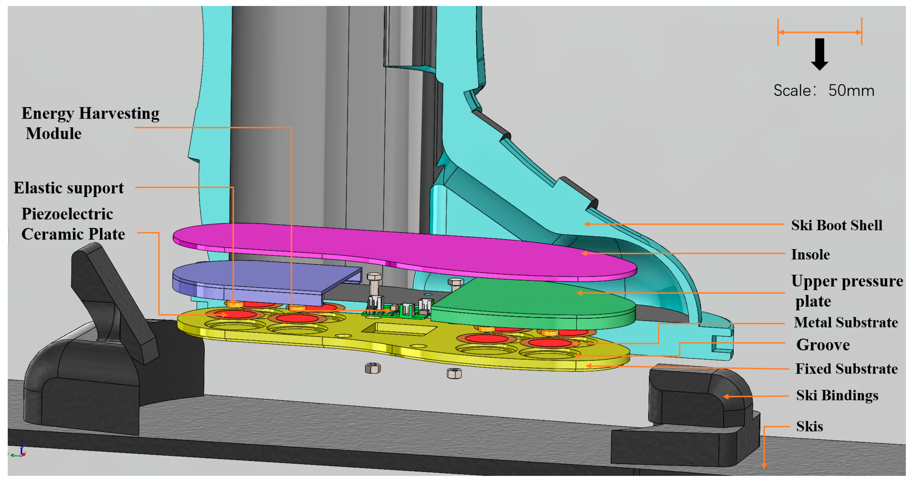
Figure 1. Exploded view of a PEHS for self-powered ski boots.
Coatings 15 01288 g001
Figure 2. Overall layout diagram. (a) Overall assembly. (b) Physical photograph.
Coatings 15 01288 g002
Figure 3. FEA model of the PEHS.
Coatings 15 01288 g003
Figure 4. Stress contour plot of the PEHS.
Coatings 15 01288 g004
Figure 5. Deformation contour plot of the PEHS.
Coatings 15 01288 g005
Figure 6. Voltage contour plot of the PEHS.
Coatings 15 01288 g006
Figure 7. Voltage curves from different materials.
Coatings 15 01288 g007
Figure 8. Model and photograph of experimental setup. (a) Model of experimental; (b) Photograph of experimental setup.
Coatings 15 01288 g008aCoatings 15 01288 g008b
Figure 9. Energy harvesting DC output circuit.
Coatings 15 01288 g009
Figure 10. Maximum instantaneous power output from a load resistor.
Coatings 15 01288 g010
Figure 11. Maximum instantaneous power output from a Frequency.
Coatings 15 01288 g011
Figure 12. Photograph of experimental setup.
Coatings 15 01288 g012
Figure 13. Peak power output from 3 actions.
Coatings 15 01288 g013
Table 1. Parameters of the test prototype.
ParametersNumerical and Material
size of prototypes (excluding skis)316 mm × 119 mm × 285 mm
diameter of piezoelectric ceramic plate25 mm
diameter of metal substrate35 mm
diameter of elastic support10 mm
height of piezoelectric ceramic plate0.25 mm
height of metal substrate0.35 mm
height of elastic support3.0 mm
materials of fixed substratePLA (3D-Printed)
materials of upper pressure platePLA (3D-Printed)
materials of elastic supportPLA (3D-Printed)
materials of metal substrateberyllium Copper
density of piezoelectric ceramic plate (PZT-5H; PZT-5A; PZT-4)7480 kg·m−3
density of metal substrate8295 kg·m−3
density of PLA (3D-printed)1382 kg·m−3
equivalent elastic modulus of piezoelectric ceramic plate (PZT-5H)52 GPa
equivalent elastic modulus of piezoelectric ceramic plate (PZT-5A)53 GPa
equivalent elastic modulus of piezoelectric ceramic plate (PZT-4)71 GPa
elastic modulus of metal substrate131 GPa
elastic modulus of PLA (3D-printed)2170 MPa
poisson’s ratio of piezoelectric ceramic plate0.36
poisson’s ratio of metal substrate0.34
poisson’s ratio of PLA (3D-printed)0.365
Disclaimer/Publisher’s Note: The statements, opinions and data contained in all publications are solely those of the individual author(s) and contributor(s) and not of MDPI and/or the editor(s). MDPI and/or the editor(s) disclaim responsibility for any injury to people or property resulting from any ideas, methods, instructions or products referred to in the content.