Article

The Influence of Multi-Level Structure on the Bearing and Crack Propagation Mechanism of Tooth Enamel

1
College of Mechanical Engineering, Jiangsu University of Science and Technology, Zhenjiang 212000, China
2
Department of Orthodontics, Central Laboratory of Jinan Stamotological Hospital, Jinan Key Laboratory of Oral Tissue Regeneration, Jinan 250001, China
*
Author to whom correspondence should be addressed.
These authors contributed equally to this work.
Coatings 2025, 15(11), 1255; https://doi.org/10.3390/coatings15111255
Submission received: 12 September 2025 / Revised: 16 October 2025 / Accepted: 22 October 2025 / Published: 30 October 2025
(This article belongs to the Section Surface Coatings for Biomedicine and Bioengineering)

Abstract

Dental enamel exhibits a unique combination of high hardness and high toughness. This outstanding mechanical property is closely tied to its multi-scale hierarchical structure. In this study, rat tooth enamel was selected as the research object, the different structural layers and mechanical properties of tooth enamel were investigated and characterized experimentally. The multi-scale mechanical models with different structural layers were developed and analyzed using numerical simulations. The research results indicate that, regarding the load-bearing mechanism, the outer layer of tooth enamel consists of hydroxyapatite crystal bundles arranged in parallel and inclined orientations, and this structural feature enables it to exhibit excellent elastic modulus and resistance to deformation, while the inner layer with cross-arranged crystal bundles shows different mechanical response characteristics. In terms of crack propagation behavior, the outer layer is more prone to crack initiation due to the consistency of crystal orientation, and the cracks tend to extend in a straight line, while the unique cross arrangement of crystals in the inner layer can effectively inhibit crack propagation by inducing crack deflection and branching mechanisms, thus demonstrating more excellent fracture toughness. This “outer hard and inner flexible” gradient structure design elucidates the synergistic mechanism between crystal orientation and crack propagation behavior in tooth enamel, offering significant design insights for biomimetic composite materials.

1. Introduction

The exceptional mechanical properties of natural biological materials are primarily attributed to their distinctive structural features, as evidenced by the evaluation methods and applications detailed in recent research. Taking hard tissues such as bones, teeth, and shells as examples, they are composed of nanocomposites of proteins and minerals and possess outstanding mechanical properties [1]. Research has found that these biological materials generally have multi-scale hierarchical structures. This hierarchical organisational structure not only enables the materials to grow through self-assembly but also allows for adaptive adjustments according to different scale functional requirements [2], thereby achieving ideal mechanical properties. Enamel has typical characteristics of a biological mineral composite material. Its composition contains up to 92%–96% inorganic substances, mainly including hydroxyapatite crystals, in addition to 1%–2% organic matter and 3%–4% water [3]. The hardness of the enamel contact area is approximately 5.35 ± 0.19 GPa, the elastic modulus is approximately 98.1 ± 1.5 GPa [4], and the fracture toughness is 1.244 ± 0.12 MPa·m0.5 [5], which is much higher than the fracture toughness of hydroxyapatite crystals (0.3 MPa·m0.5). This remarkable enhancement in performance is primarily attributed to the precise hierarchical structure design of enamel. In-depth analysis of the structure-activity relationship of the multi-level structure and performance of enamel not only helps to understand the adaptive selection mechanism of teeth during long-term evolution but also provides an important theoretical basis and structural biomimicry strategies for the development of new biomimetic dental materials.
Numerous studies have investigated the internal fracture resistance mechanism of enamel. Enamel exhibits gradient mechanical properties [6,7]. The inner layer of enamel exhibits lower elastic modulus and yield strength compared to the outer layer; additionally, it demonstrates superior energy dissipation properties but inferior resistance to deformation. Furthermore, the non-uniform distribution of mineral crystals within the enamel rods enhances energy dissipation properties, while maintaining sufficient stiffness [8]. Although proteins account for a small proportion of enamel, their presence reduces the elastic modulus of enamel, and the structural and compositional characteristics of trace protein components significantly regulate the mechanical properties of enamel to better meet its functional requirements [9]. Moreover, studies on the deproteinization of enamel have shown that once the protein components are absent, HAP nanocrystals will spontaneously aggregate, the ordered nanostructure of enamel is disrupted, and surface wear occurs primarily through the overall removal of HAP aggregates, thereby reducing wear resistance [10]. SEM images and PIC images reveal that the c-axis orientation difference between adjacent nanocrystals typically ranges from 1° to 30°. Experiments demonstrate that cracks extend when the orientation difference is 0° or 47°, whereas they deflect when the difference is 14°. Thus, the orientation difference between adjacent crystals within a certain range may cause the crack to deflect. This toughening mechanism helps with the unique elasticity of enamel, enabling it to withstand extreme physical and chemical challenges throughout a lifetime [11]. In nature, the enamel of different species exhibits a variety of structures at different scales, and enamel can be classified into six levels, from individual HAP crystals to different forms of enamel. It is found that the mechanical properties of different levels exhibit distinct characteristics, yet they interact with one another. Research indicates that as the degree of hierarchicalization increases, the strength decreases, but the fracture toughness increases, ultimately resulting in a combination of high fracture strength and special toughness in enamel [12]. In the study of the mechanical mechanism of enamel crack propagation, it is found that enamel with a gradient elastic modulus and toughness promotes crack propagation on the outside and inhibits it on the inside. To propagate a crack to the enamel-dentin junction, a significantly greater force than usual is necessary. For enamel without gradient changes, the crack will penetrate to the enamel-dentin junction [13]. Based on the different arrangement forms of inner and outer enamel rods at the micro-nano scale, previous studies proposed a two-layer structure model for cyclic indentation finite element analysis. Through analysis, it was concluded that the outer enamel layer, due to its greater ability to resist contact deformation, bears the main load, whereas the inner enamel layer experiences greater equivalent plastic strain and lower stress during the cyclic process. The inner layer of enamel has better resistance to fracture [14]. Research has indicated that clustered cracks are a primary cause of severe damage in tooth enamel, as supported by studies examining the etiology of enamel fissures. Furthermore, the immersion of organic matter into the cracks demonstrates that with fluid supplementation, the propagation of cracks is further retarded. Research shows that the survival strategy of teeth is not an avoidance strategy but a damage containment strategy to ensure that tooth cracks expand stably throughout a person’s lifetime [15,16]. As a hierarchical-structured biomaterial, enamel possesses both rigidity and damage tolerance. Even though enamel contains microcracks of different scales, it can still withstand mechanical loads [17]. In order to accurately determine the fracture parameters of tooth enamel, based on the concentration of enamel minerals, non-uniform mechanical properties and virtual crack closure technology, a calculation model for the non-uniform fracture of enamel was established. A dummy node fracture element for enamel was constructed. Through comparison with the actual analysis, it was proved that the dummy node fracture element for enamel has high accuracy and can more accurately solve the stress intensity factor of tooth enamel, providing a new numerical method for the prevention and treatment of dental diseases [18]. In previous studies on the finite element method, different friction coefficients were used to quantitatively determine the wear coefficient of tooth enamel under different enamel column inclinations. The results showed that there was an optimal enamel column inclination that minimized the effective wear of tooth enamel [19]. The cracks in the idealized enamel structure were simulated using the discrete element method (DEM). The microstructure of the enamel rods was explicitly represented by DEM elements. The relative strength and stiffness between the enamel rods and the interface were evaluated. It was found that the high-strength enamel rods could promote the deflection and branching of interface cracks [20]. Previous studies employed a three-dimensional representative volume element (RVE) model to investigate the deformation and damage behavior of the microstructure of fibers. A continuous damage mechanics model coupled with hyperelasticity was developed to simulate the initiation and evolution of damage in mineral fibers and protein matrices. The cohesive force model was used to capture the debonding at the interface between mineral fibers and protein, and the simulation results were verified by comparing them with the data from two multi-level micro cantilever beam test experiments [21].
Through long-term evolutionary processes, animal teeth have developed unique microscopic structures and chemical compositions, forming an intricate natural biological friction system within the complex oral environment. Taking rat teeth as an example, their incisors undergo continuous growth and wear throughout their lifespan, consistently maintaining sharp tips. During feeding, their teeth endure substantial pressure and exhibit superior mechanical properties. Therefore, the enamel of rat incisors is an excellent biomimetic object. This study systematically elucidated the intrinsic correlation between the exceptional mechanical properties of rat teeth, namely high hardness and high toughness, and their multi-level microstructure, as evidenced by the detailed morphological and mechanical performance research on Wistar rat molars. Although numerous studies have validated this relationship through mechanical experiments [22], there remains a dearth of quantitative models grounded in microstructural characteristics to elucidate the influence mechanism of enamel crystal orientation and deflection on the load-bearing mechanism and crack propagation. Therefore, this research developed micro-mechanical models featuring distinct crystal arrangement patterns to investigate the influence of hierarchical structures on the load-bearing capacity and fracture resistance of teeth, as supported by biomechanical studies. The research outcomes not only clarified the “structure-performance” relationship of enamel but also provided substantial theoretical support for the optimized design of innovative biomimetic dental materials. All experiments in this study strictly adhered to animal ethics regulations and did not involve any human or clinical trials.

2. Materials and Methods

2.1. Rat Modeling

This study employed the teeth of experimental SD rats as research subjects. The related research has passed the welfare and ethics review of Jiangsu University of Science and Technology (approval number: G2024JX09). The experimental rats were provided for breeding by the Experimental Animal Centre of Jiangsu University, which holds the animal license number SCXK 2023-0017. During the modeling period, all rats were provided with distilled water, and specialized feed was supplied by Jiangsu Xiehe Pharmaceutical Biotechnology Engineering Co., Ltd. (Changzhou, Jiangsu, China). The diet was based on the AIN93G standard model. As shown in Figure 1a, five rats were selected to be fed with standard feed for four months until their teeth matured. After deep anaesthesia was administered, the rats were euthanized by intraperitoneal injection of an overdose of pentobarbital sodium solution. The teeth of the rats were collected for microscopic morphological and mechanical property analysis. Six samples of upper incisors were randomly selected from different rats for subsequent experiments.

2.2. Methods for Preparing Tooth Samples

Following euthanasia, the upper incisors of the rats were extracted using sterile instruments. Subsequently, the surrounding gum tissues were trimmed, and the teeth were stored in distilled water at 0–4 °C for future use. As shown in Figure 1b, the incisors with the distal and labial surfaces were covered with cold resin, and a sample with a diameter of 25 mm was prepared. For the classification of abrasive particle sizes, refer to the GOST 9206-80 standard. The surface of the sample was polished successively using diamond polishing compounds of W5, W3.5, and W1.5 (Particles with a maximum particle size of D100 as the nominal value, and with a specific concentration (D50), in sizes of 5 µm, 3.5 µm, and 1.5 µm) under water cooling conditions, resulting in a smooth surface of the sample.

2.3. Microscopic Observation

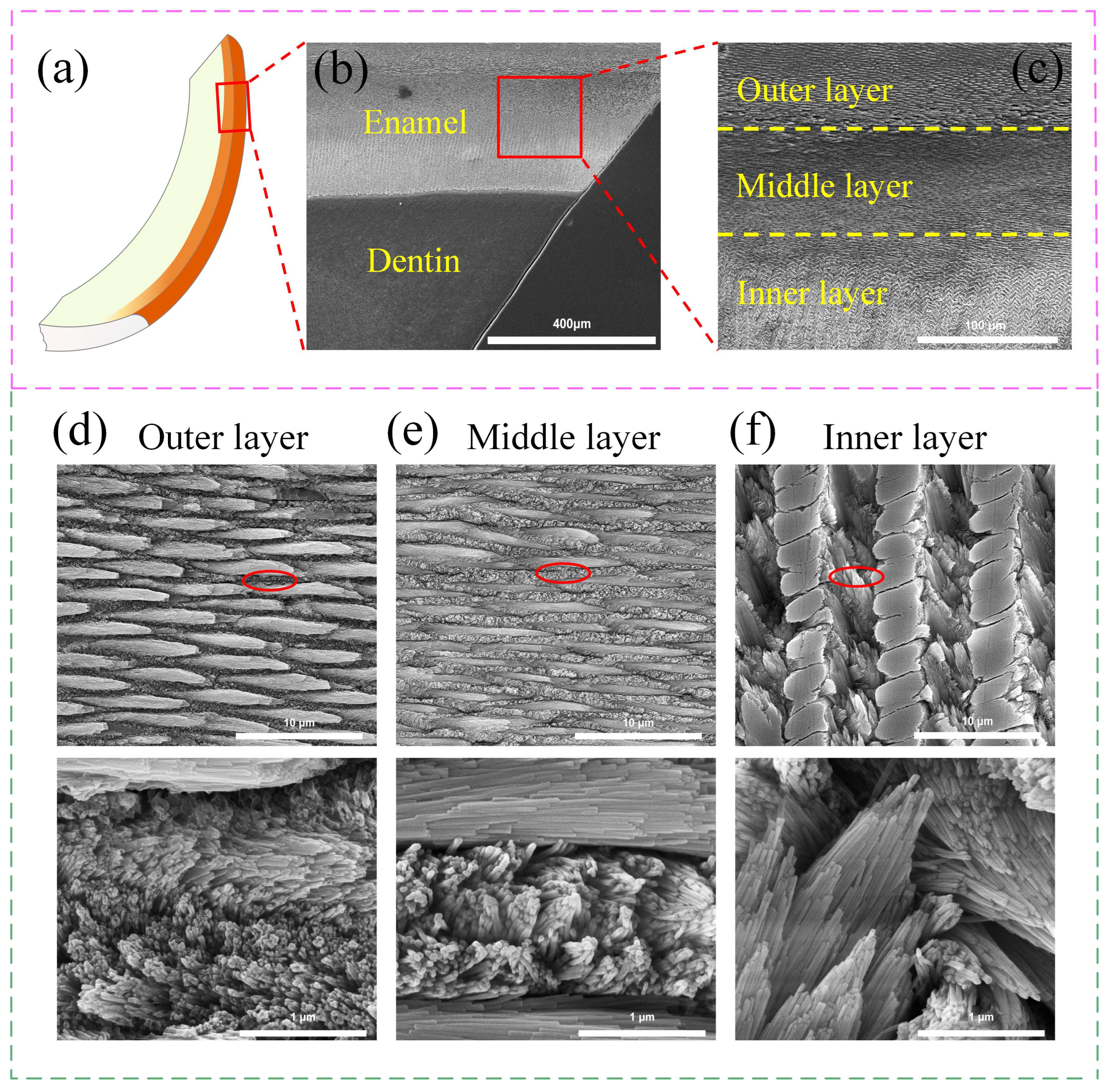
The distal surfaces of the extracted incisors were etched with 0.002 mol/L citric acid for 5 min, followed by gold spraying. The microstructure was observed using a scanning electron microscope (SEM, Quanta FEG250, FEI, Hillsboro, OR, USA). The microstructure of the upper incisors of SD rats was revealed in Figure 2 through microscopic examination. It can be clearly seen that the enamel and dentin are separated by the enamel-dentin junction (EDJ) (Figure 2b). As shown in Figure 2c, based on the different arrangements of crystal bundles, enamel can be divided into three layers: the outer layer, the middle layer, and the inner layer. The crystal bundle arrangement of the outer layer is parallel-inclined (Figure 2d), while that of the middle layer is parallel-vertical (Figure 2e), and that of the inner layer is in an intersecting manner (Figure 2f). Through measurement, the length of the enamel column composed of parallel crystal bundles is 5–12 μm, the width is 0.5–1.23 μm. The arrangement angle of the parallel crystal bundles is nearly 0°. The arrangement angle of the inclined crystal bundles varies, most of which are close to 70°. The arrangement angle of the vertical crystal bundles is nearly 90°, and the arrangement angle of the intersecting crystal bundles is close to 45°.

2.4. Mechanical Performance Characterization

The hardness of different layers on the distal surface of the incisor samples was evaluated using the automatic microhardness testing system (HVS-1000XAT, Grow Instrument, Shanghai, China). The applied load during the test was 200 g. The morphology of the indentation was analyzed using a laser confocal microscope (LCSM, VK-X1000, Keyence, Osaka, Japan), with careful consideration given to the selection of appropriate laser wavelengths and filters, scanning methods (including point, line, and 3D scanning), and resolution settings (e.g., 256 × 256, 512 × 512, 1024 × 1024, 2048 × 2048) to ensure high-quality imaging. The average length of the diagonal of the indentation, the average length of the cracks at the four corners of the indentation, and the fracture toughness [23] data could be calculated through Formula (1):
K c a p p = 0.0084 E H v 0.4 2 F L 1 c 0.5 MPa m 0.5
In the formula, Kc(app) denotes the fracture toughness, E represents the elastic modulus (in GPa), Hv stands for the Vickers hardness, F indicates the loading force (in N), L signifies the average length of the diagonal of the indentation (in mm), and c represents the average length of the four cracks at the indentation corner (in mm).

2.5. Modeling Method

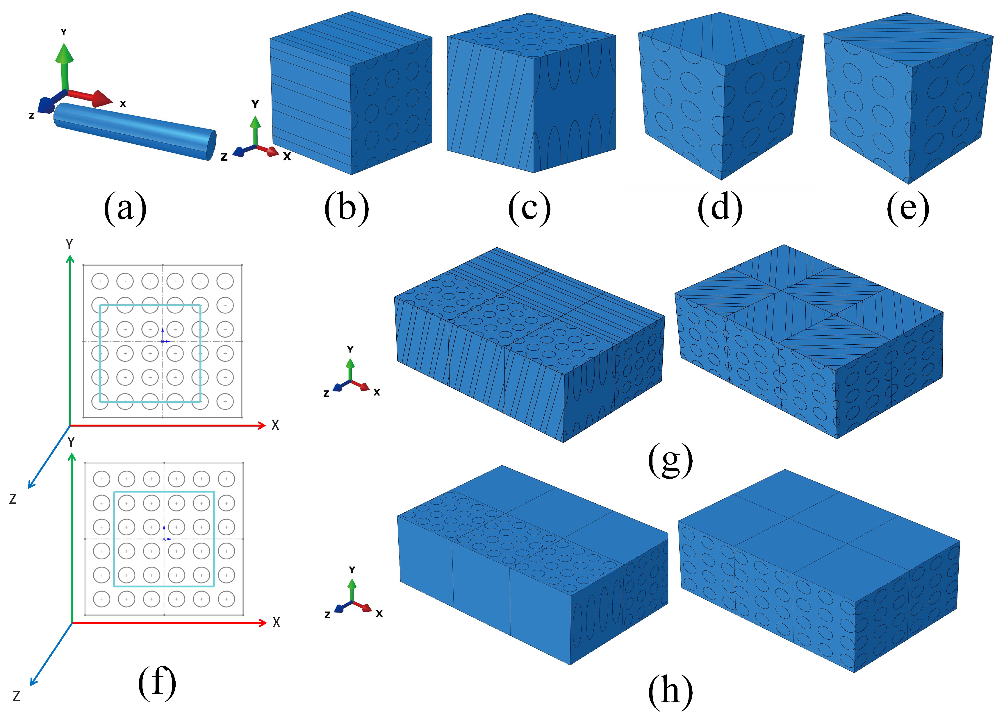
To simulate the hierarchical structures of the inner enamel in rat incisors, the initial step involves considering the arrangement of crystal bundles. As shown in Figure 3a, based on the microscopic structure of different layers of enamel, the crystal bundles are simplified and modeled as cylindrical shapes with a length of 1.2 μm and a diameter of 0.2 μm. The interval between crystal bundles is 0.1 μm, and proteins are filled in between the crystal bundles [24,25]. In the model, 4 × 4 crystal bundles are set as one module, with each module having a length, width, and height of 1.2 μm.
Based on the crystal bundles, four different modules are established by combining different angles. The hierarchical structure of enamel consists of 12 modules, including 96 crystal bundles. When combined with the observation results, this structure facilitates model analysis. The angle of the outer parallel crystal bundles is set at 0°, the inclined crystal bundles at 75°, and the inner cross crystal bundles at 45°. The overall dimensions of the hierarchical structure are 3.6 μm in length, 2.4 μm in width, and 1.2 μm in height. Type I module: establish the crystal bundle axis in the XOY plane and the angle with the X-axis in the crystal column as 0° (Figure 3b); Type II module: establish the crystal bundle axis in the XOY plane and the angle with the X-axis as 75° in the crystal column (Figure 3c); Type III module: establish the crystal bundle axis in the XOZ plane and the angle with the X-axis as 45° in the crystal column (Figure 3d); Type IV module: establish the crystal bundle axis as the reverse of Type III (Figure 3e).
As shown in Figure 3g,h, the outer structure of enamel is composed of three Type I crystal bundles in the upper region and three Type II crystal bundles in the lower region. The inner structure of enamel consists of two interwoven Type III crystal bundles and one interwoven Type IV crystal bundle in the upper region, along with two interwoven Type IV crystal bundles and one interwoven Type III crystal bundle in the lower region. Additionally, the overall modeling approach for indentation and crack simulation in this study adheres to the aforementioned principles; however, there exist certain differences. As shown in Figure 3f, for indentation simulation [26], the crystal bundles are exposed on the surface, while for crack simulation, they are surrounded by proteins. Nevertheless, the overall dimensions of two modeling approaches remain consistent.

2.6. Indentation Finite Element Model

Indentation finite element simulation was used to analyze the chewing motion patterns of teeth, and a mechanical analysis was conducted on the structure, which consists of a single inclined crystal beam as well as the outer and inner layers of tooth enamel. Subsequently, the load-bearing mechanism of the structure was observed. First, the model was constructed using SOLIDWORKS 2021, saved in STEP format, and then imported into ABAQUS 2024 for subsequent analysis. The Berkovich method was utilized, and the corresponding drawing was directly created in ABAQUS. Commercial nanoindentation tests typically employ a diamond indenter, characterized by a density of ρ = 3.52 g/cm3, and the elastic modulus and Poisson’s ratio of the diamond indenter are E = 1141 GPa and v = 0.07, respectively. According to the literature, the elastic modulus of the crystal bundle was set at 75 GPa, the density to 3.16 g/cm3, the Poisson’s ratio to 0.3, and the yield stress to 1.7 GPa [27,28]. The elastic modulus, Poisson’s ratio, and yield stress of the protein were set to 4.3 GPa, 0.3, and 400 MPa, respectively. In this study, both the crystal beam and the protein were defined as continuous, homogeneous, and isotropic nonlinear materials. A large number of previous studies have proved that this simplified setting is currently acceptable [29,30]. Therefore, this study simplified the actual physical environment of tooth enamel. In the finite element simulation, the indenter was set as a rigid body and a reference point RP-1 was established as the motion reference. Since the rigid body remains undefoemed, a single point can represent the displacement of the entire rigid body. As shown in Figure 4a, the initial point of the indentation was set at the middle position of the model, i.e., the coordinate (1.8, 0, 1.2). The general contact was set up to include both tangential and normal interactions, with the tangential friction coefficient set at 0.01. It was hypothesized that there existed a perfect bond between the protein and the crystal beam. The outer layer model for the indentation simulation had a total of 373,885 elements, and the inner layer model had 339,230 elements. All models were discretized using 4-node linear tetrahedral elements (C3D4 in ABAQUS 2024). The crystal beam featuring a single inclined angle, was indented by 0.15 μm. Meanwhile, the outer and inner layer models were indented by 0.15 μm, 0.25 μm, and 0.35 μm, respectively. The analysis time step was configured to 10 μs, and the model was elevated at 5 μs. Figure 4b shows the boundary conditions. The bottom end was fixed, and the displacement along the Y-axis corresponded to the indentation distance. Finally, field and history outputs were conducted.

2.7. Finite Element Model of Crack Analysis

The finite element simulation of tooth cracking behaviour was conducted using cracks [31]. Specifically, the Cohesive element was employed to simulate crack expansion, while the study focused on how crystal bundle arrangement affects crack propagation paths and deflection. According to the literature, the elastic modulus of the crystal bundle was set at 75 GPa [32], the density was 3.16 g/cm3, and the Poisson’s ratio was 0.3. The elastic modulus of the protein was set to 4.3 GPa, and its Poisson’s ratio was 0.3, and the yield stress was 400 MPa [33]. Different from the material properties in indentation simulation, the yield stress of the crystal bundle was not set. This is because hydroxyapatite in teeth is generally resistant to fracture, and when the occlusal surface experiences contact loading, its yield behaviour is primarily supported by the proteins located between the elongated hydroxyapatite crystal grains [34]. As shown in Figure 4c, to simulate the fracture mechanics properties of tooth enamel, cracks were pre-embedded in the outer and inner layer models, with a crack length of 1.05 μm, a width of 0.1 μm, a height of 1.2 μm. It was situated on the XZ plane, extended throughout the Y-axis and stretching along the -Z direction. Given that the specific form of the cohesive force and crack opening displacement curve has little influence on the simulation results, this study adopted a bilinear constitutive model for simulation, as evidenced by the applicability and validation of similar models in various materials and conditions.
The existing traction-separation model in Abaqus assumes an initial linear elastic behaviour, followed by the initiation and evolution of damage. Elastic behaviour is represented by an elastic constitutive matrix, which links the nominal stress and nominal strain at the interface. Elastic behaviour can be written as:
t   =   t n t s t t   =   K n n K n s K n t K n s K s s K s t K n t K s t K t t δ n δ s δ t = K δ
Among them, the diagonal stiffness matrix used to describe the elastic behaviour of the interface is K. The vector of the traction stress is t, and the three components are t n , t s and t t . The corresponding separation is represented by δ n , δ s and δ t . In this study, the maximum nominal stress criterion is adopted to determine the onset of damage. When the maximum nominal stress ratio attains a value of 1, it is assumed that damage initiation has occurred. This criterion can be expressed as:
max   = t n t n o ,   t s t s o ,   t t t t o = 1
Among them, t n is the component perpendicular to the potentially cracked surface, while   t s and t t are the two shear components on the potentially cracked surface. The potentially cracked surface will be orthogonal to either the direction of local coordinate axis 1 or that of axis 2. t n o , t s o , and   t t o represent the peak values of the stress.
The damage evolution law describes the rate at which the material stiffness degrades after reaching the corresponding initial criterion. The scalar damage variable D represents the overall damage of the material and captures the combined effect of all effective mechanisms. Its initial value is 0. If the damage evolution is modeled, then during the loading process after the damage occurs, D monotonically evolves from 0 to 1. The stress components of the traction-separation model are affected by damage:
t n =   1 D t n ¯ ,     t n ¯ 0 t n ¯ ,
  t s = 1 D t s ¯
  t t = 1 D t t ¯
Among them, t n ¯ ,   t s   ¯ and   t t ¯ are the stress components predicted for the elastic traction separation behaviour when there is no damage at the current stage. To describe the damage evolution under the combined effects of normal and shear deformations at the interface, it is necessary to introduce the effective displacement, defined as:
δ m =   δ n 2   +   δ s 2   +   δ t 2
According to the bilinear constitutive model, set the pure normal stress and the first tangential stress and the second tangential stress to 100. The failure displacement is determined by the unit grid and let δ f = 0.001. δ o is generally 1/10 of δ f , that is, δ o = 0.0001. According to Equation (1), K = t/δ = 100/0.0001 = 1 e 6 . The constitutive thickness value is generally related to the difficulty of material cracking. In this study, it is set to 0.01. Therefore, the surface force E/Enn = G1/Ess = G2/Ett = 1 × 106 × 0.01 = 1 × 10⁴. The cohesive force model in the outer and inner layers uses 4-node three-dimensional bonding elements (COH3D6 in ABAQUS 2024) for meshing. The outer layer contains 139,869 elements, and the inner layer has 176,040 elements. The remaining parts are meshed with 4-node linear tetrahedral elements (C3D4 in ABAQUS 2024), where the outer layer has 382,141 elements and the inner layer has 426,031 elements. The general contact setting adopts tangential and normal behaviors, and the tangential friction coefficient is 0.3. The mesh type of the cohesive force element is linear and viscous. The element deletion method is employed, with a maximum reduction of 0.99. During the calculation process, the analysis step is set to 1 μs. Figure 4d shows the boundary conditions. Coupling is carried out at the two end faces located at Z = 2.4 μm. The left end face is coupled at point RP-1, while the right end face is coupled at point RP-2. Displacements of 0.15 μm are applied outward to these two points, and the Z = 0 μm plane is fixed. Finally, the analysis and calculation are carried out.

3. Results and Discussion

3.1. The Hardness and Fracture Toughness of Enamel from the Outer Layer to the Inner Layer

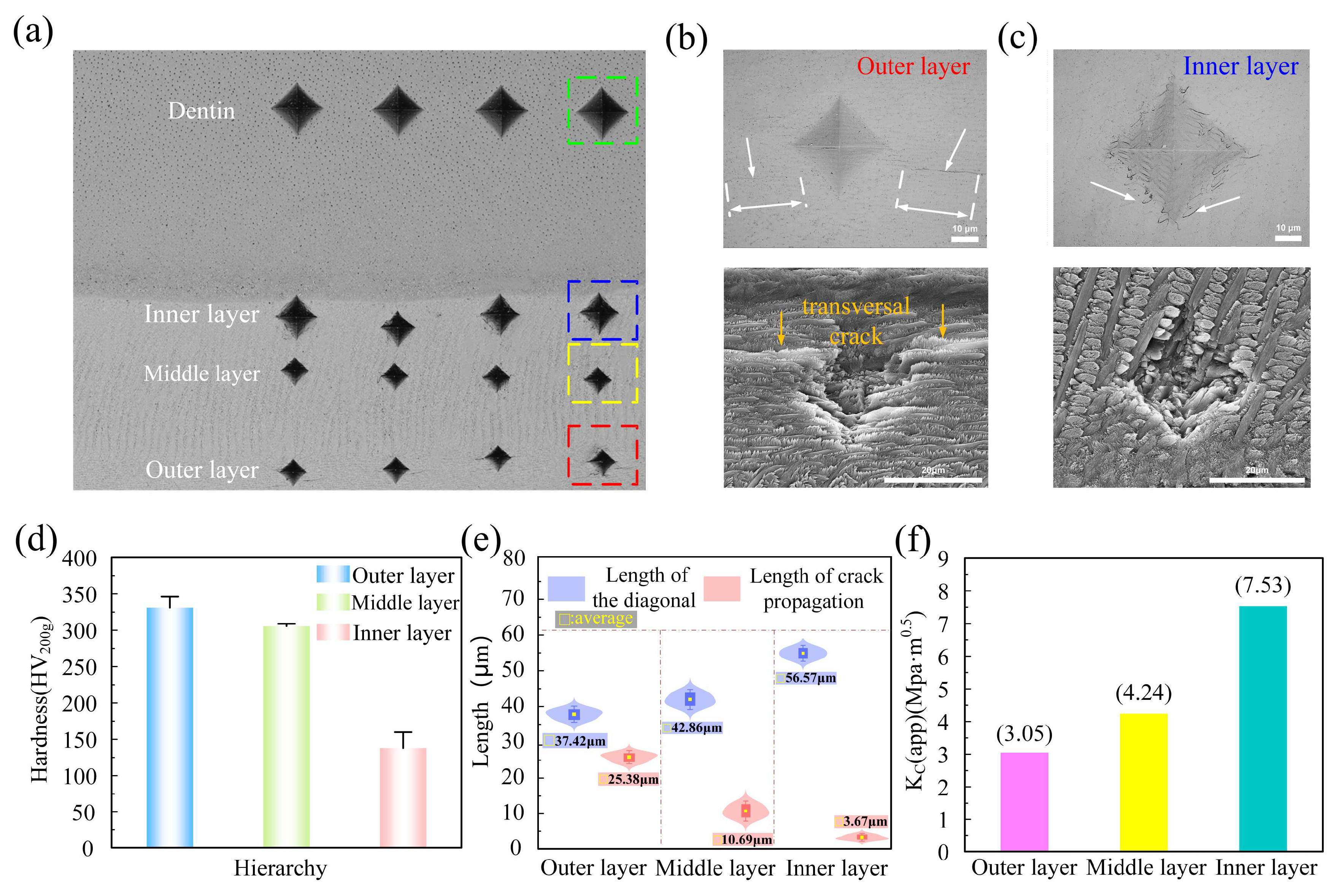
The enamel, which forms the outermost layer of the tooth, is known for its exceptional hardness and fracture toughness, ranking just below diamond on the Mohs scale, with a mineral content of up to 96%–97%.The enamel of the rat’s incisors is divided into three layers from the enamel-dentin junction (EDJ) to the outer enamel surface (OES): the inner layer, the middle layer, and the outer layer [35]. In this section, the hardness of tooth enamel was tested from the outer surface to the inner part. The crack propagation around the indentation points on the outer and inner layers of the enamel was observed using scanning electron microscopy, and the differences in fracture toughness were compared based on the crack propagation lengths, as shown in Figure 5. According to Figure 5a, the indentation points on the distal surface of the incisor gradually increase from the outside to the inside, indicating that the hardness of the enamel gradually decreases from the outside to the inside. By magnifying the local areas of the indentation points on the outer and inner layers of the enamel, as shown in Figure 5b,c, it can be seen that there are obvious long and thin transverse crack extensions around the outer layer indentation points, while the inner layer indentation points are surrounded by multiple short and deflected micro-cracks, and the transverse crack extension is restricted. As can be seen from Figure 5d, the hardness of enamel decreases from the outer layer to the inner layer. This decrease in hardness can be attributed to structural changes within the enamel. Additionally, as shown in Figure 5e, from the outer layer to the inner layer, the diagonal length of the indentation points gradually increases under the same load conditions, which is consistent with the hardness results. The crack lengths around the indentation are constantly decreasing, with the longest crack extension length in the outermost layer. Utilizing the built-in measurement software of the VK-X1000 system to quantify the crack extension lengths across each layer of dental enamel, it becomes evident that the fracture toughness of dental enamel progressively enhances from the outer layer towards the inner layer.

3.2. The Impact of Multi-Level Structure on Tooth Bearing Mechanism

This paper quantifies the elastic-plastic mechanical properties of tooth enamel from the perspectives of force-displacement response, load-penetration depth response, stress–strain response, and plastic energy dissipation, taking into account the structure and deflection angle [36,37]. In the numerical simulation, the load is represented by RF, representing the reaction force generated by the model at the constrained area, which is equal in magnitude and opposite in direction to the applied load. Displacement is defined as the distance over which the rigid body is pressed downward. Plastic energy dissipation is denoted by ALLPD and is recorded in the software’s history output. Stress is defined as Mises stress, which converts the complex multi-axis stress state ( σ 1 ,   σ 2 , σ 3 ) into a scalar value, and the formula is:
σ M i s e s = σ 1 σ 2 2 + σ 2 σ 3 2 + σ 3 σ 1 2 2
Among them, σ 1 , σ 2 and σ 3 are the principal stresses in the X, Y, and Z directions of the coordinate system. In this study, strain is quantified using the parameter PEEQ, which represents the equivalent plastic strain and serves as a standard measure of the plastic strain tensor. The calculation formula is:
PEEQ   =   2 3 ε i j p ˙ ε i j p d t ˙
Here, ε i j p ˙ represents the plastic strain rate tensor. When PEEQ > 0, it indicates that plastic deformation occurs within the region.

3.2.1. Load–Indentation Depth Response Curve

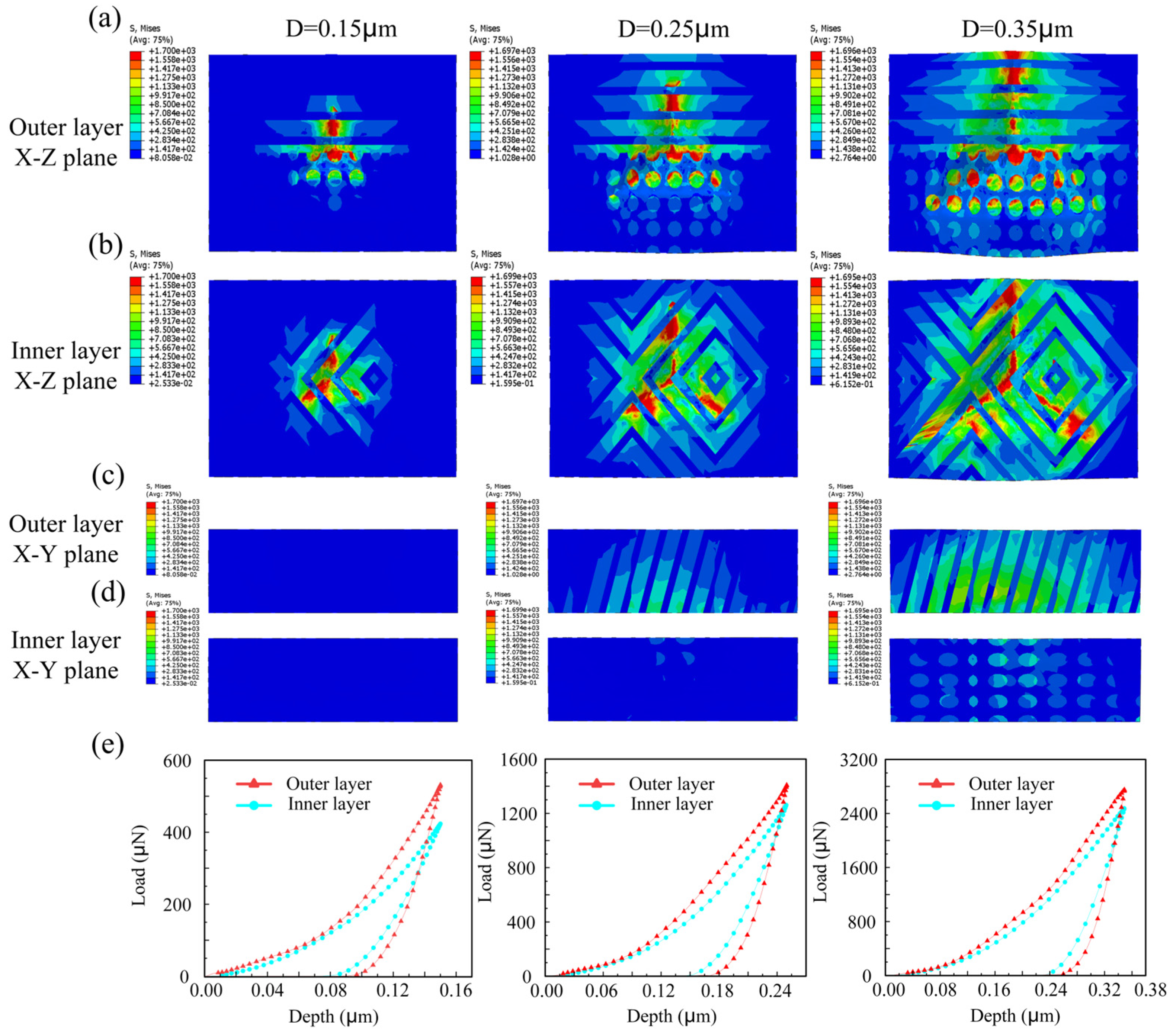
As shown in Figure 6a–d, the stress maps in the XZ plane and XY plane of the outer and inner layers under specific indentation depths (D = 0.15 μm, 0.25 μm, 0.35 μm) are depicted. As shown in Figure 6a,b, on the XZ plane, as the indenter penetrates deeper, it can be observed that the stress of the inner layer mainly concentrates in the area corresponding to the edge line of the indenter, while the stress of the outer layer, in addition to being distributed in the area corresponding to the edge line, also concentrates on the inclined crystal beam. As shown in Figure 6c,d, on the XY plane, when the indenter is pressed into 0.15 μm, almost no stress concentration is observed. As the indenter penetrates deeper, it is evident that the stress in the outer layer initially expands from the bottom to the top, primarily concentrating on the inclined crystal beam and exhibiting a continuous distribution. In contrast, the inner layer exhibits that the stress initially appears at the top and then gradually extends to the bottom, and the stress presents a discontinuous distribution, which is closely related to the cross-parallel arrangement of the inner layer crystal beams. This combination ensures that, under external loads, stress primarily concentrates at the bottom of the outer layer and subsequently propagates to the top of the inner layer, which not only prevents external damage to the enamel but also mitigates internal damage. It plays a buffering role in extension of damage to the dentin and the tooth root.
The numerical simulation not only describes the phenomenon that the unloading curve does not coincide with the loading curve, but also accurately depicts the phenomenon of stiffness reduction during the unloading process. As shown in Figure 6e, when the downward pressure depth is 0.15 μm, 0.25 μm, and 0.35 μm, the maximum load values of the outer layer are 531 μN, 1408 μN, and 2750 μN, respectively, while the maximum load values of the inner layer are 423 μN, 1261 μN, and 2475 μN, respectively. Thus, it can be seen that when the downward pressure reaches the same depth, the maximum load required by the outer layer is higher than that of the inner layer. From the loading curve, it can be observed that under the same load, the pressing depth of the inner layer is always greater than that of the outer layer. Therefore, it can be concluded that the stiffness of the outer layer of enamel is greater than that of the inner layer. When subjected to external pressure, the outer layer is more capable of resisting deformation than the inner layer.

3.2.2. Stress–Strain Curve

To characterize the mechanical properties of the outer and inner layers of tooth enamel, the stress–strain relationship was evaluated. In the Abaqus2024 software, the volume averaging method was employed to track and record the indentation area, and stress–strain data were obtained.
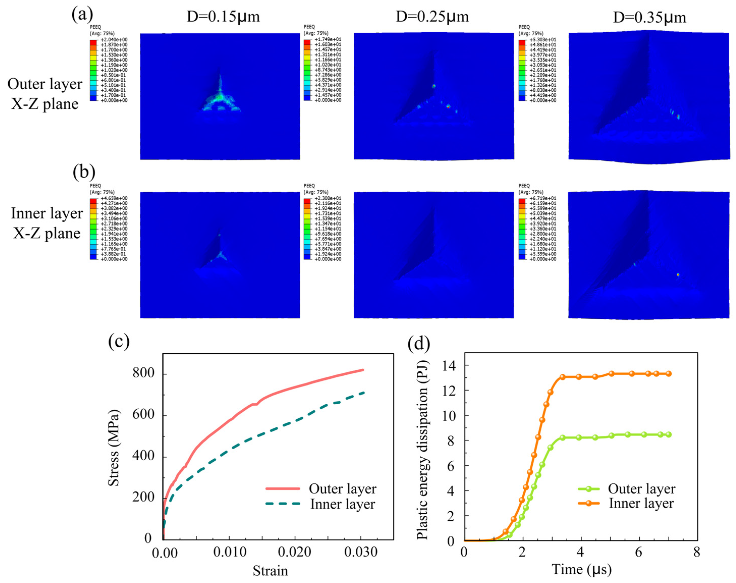
As shown in Figure 7a,b, the strain maps of the outer layer and the inner layer after being pressed into the XZ plane with thicknesses of 0.15 μm, 0.25 μm, and 0.35 μm are presented. It can be observed that as the pressing head descends, the pressed area in both the outer layer and the inner layer continuously expands. Secondly, the maximum equivalent plastic strains corresponding to the outer layer are 2.04, 17.49, and 53.03, while those corresponding to the inner layer are 4.66, 23.08, and 67.19. From this, it can be inferred that the inner layer consistently exhibits greater maximum deformation than the outer layer, suggesting that the inner layer possesses higher toughness.
By employing the volume averaging method in Abaqus software, the stress–strain values within the indentation area were tracked and recorded. It should be noted that despite the indentation occurring in the same area and covering both the upper and lower parts of the inner and outer layers, the proportion of the crystal bundles and proteins was not balanced. Consequently, the stress–strain curves for the crystal bundles and proteins recorded separately and then averaged to obtain the stress–strain curve graph. As shown in Figure 7c, under the same stress, the strain in the inner enamel is greater than that in the outer layer, indicating that the inner enamel has lower stiffness and is more prone to deformation. During mastication, the outermost enamel layer is directly exposed to the complex oral environment, enduring various forms of wear, impact, and fatigue loads. Therefore, it needs to possess sufficient wear resistance and stiffness [38]. Meanwhile, the inner enamel and dentin, acting as a base with relatively high softness and elasticity can provide a buffering effect, effectively alleviating stress concentration within the tooth.
As shown in Figure 7d, the variation laws of plastic energy dissipation of the inner and outer layers over time were evaluated. When a material deforms under external force and does not fully recover its original shape after the force is removed, the atomic structure within the material undergoes changes during plastic deformation, leading to energy dissipation. Obviously, the plastic energy dissipation of the inner layer is significantly higher than that of the outer layer. Therefore, the structure and deflection angle of the inner layer promote energy dissipation, thereby further improving the toughness of enamel. Thus, it can be concluded that the structure and deflection angle of the inner layer significantly contribute to enhancing the plasticity of enamel.

3.3. The Influence of Multi-Level Structure on the Crack Propagation Mechanism of Teeth

The fracture mechanics properties of enamel have been quantified by considering the hierarchical structure and the role of organic components in energy dissipation, as well as the influence of the deflection angle on crack propagation. During the numerical simulation, stress was characterized using Mises stress. The energy dissipation due to crack damage was quantified using ALLDMD, resulting in output in the software’s history date.

3.3.1. Observation of Crack Path

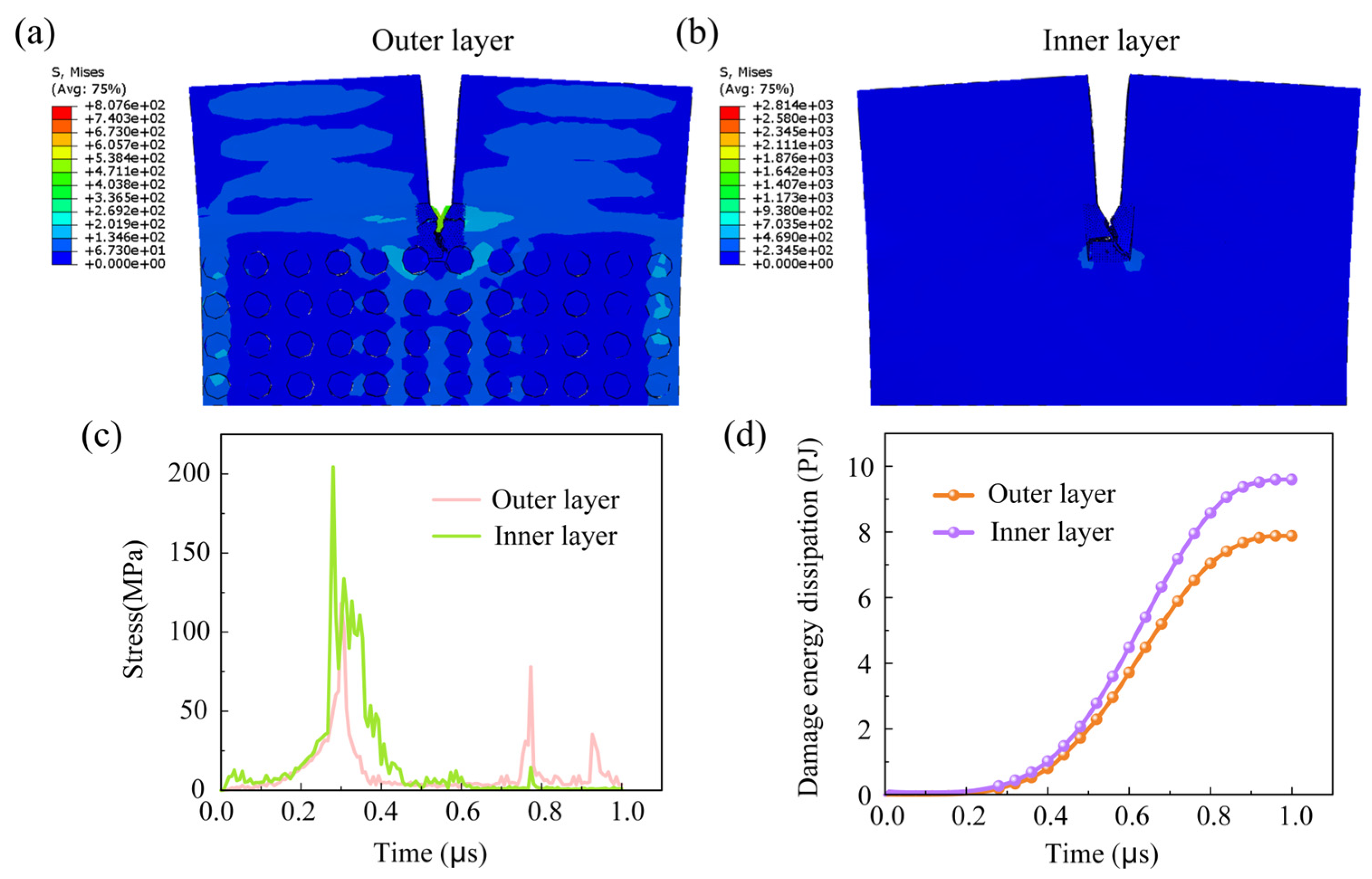
This section assesses the crack path. Figure 8a,b shows the XZ plane stress contour maps of the outer and inner layers, allowing the observation of the crack propagation path in the model, which gradually extends from the pre-existing crack tip. The outer hydroxyapatite crystals are predominantly arranged laterally or at an incline, and the crack propagation direction extends linearly along the crystal boundary or deflects at an incline. When the crack extends onto the inclined crystal bundle, it deflects. The inclined crystal bundle exerts a certain influence on crack propagation. This process can effectively prevent the crack from reaching the interior of the tooth, which is beneficial to the tooth. Compared to the outer layer, the inner layer only has one main path with cracks. Upon reaching the midpoint, a distinct bifurcation occurs. This indicates that the cross-like arrangement of inner layer crystal beams can impede crack expansion. The unique crystal arrangement pattern can effectively inhibit crack propagation through mechanisms such as inducing crack deflection and branching. Although cracks cause catastrophic damage to the enamel, their occurrence in teeth is inevitable. When organic matter infiltrates the crack, fluid replenishment occurs, which further slows crack propagation, thereby containing damage and ensuring stable crack expansion throughout the tooth’s lifetime [34]. In contrast, the outer layer has a larger number of cracks, indicating that cracks are more likely to expand in the outer layer, while the inner layer is relatively more difficult to expand. From the outer layer enamel to the inner layer enamel, cracks are guided to expand, and this structure can resist crack growth caused by damage to the tooth surface [23].

3.3.2. Time-Stress Curve

To elucidate the fracture mechanics behavior of tooth enamel, the time-stress relationship was evaluated. Numerical simulations were conducted, and the Mises stress at element points surrounding the crack was averaged to derive the stress curve over time, reflecting the mechanical behavior of both the outer and inner layers. As shown in Figure 8c, the maximum stress of the inner layer was 204.36 MPa, while that of the outer layer was 118.06 MPa. This may correspond to the stress threshold required for crack propagation to expand along the main path, which further indicates that crack propagation in the inner layer is more challenging than in the outer layer. It is noteworthy that, in comparison to the inner layer, the outer layer exhibited two relatively distinct peaks following the first stress peak, with corresponding values of 77.98 MPa and 35.38 MPa. This corresponds to the observation that, despite the relative ease of crack expansion in the outer layer, micro-cracks still emerge in addition to the main path. The appearance of micro-cracks undoubtedly consumes the force and helps resist the catastrophic damage of tooth enamel [39]. The numerical simulation results also corroborated the experimental findings. For the outer layer of tooth enamel, which consists of parallel and inclined crystal bundles, cracks are more prone to propagate bidirectionally. In contrast, for the inner layer composed of crossed crystal bundles, crack propagation is challenging and rarely occurs.

3.3.3. Crack Damage Energy Dissipation Curve

Figure 8d assesses the variation pattern of energy dissipation due to inner and outer crack damage over time, utilizing the energy dissipation ratio to construct a nonlinear statistical damage constitutive model. In the Abaqus software, the ALLDMD variable is utilized to track the energy dissipation resulting from material damage, particularly due to crack formation. Specifically, when cracks emerge within the material, the formation and propagation of these cracks are accompanied by energy dissipation, and this energy loss is primarily associated with the material’s fracture process. As can be seen from the figure, the energy dissipation curve of inner layer over time, the crack damage in the inner layer is significantly higher than that in the outer layer. This suggests that during the crack propagation process, the inner layer absorbs more energy, which leads to energy loss. The observed energy loss is intrinsically linked to the material’s fracture toughness, as evidenced by studies on microcracked materials and the impact of matrix properties on crack propagation. Materials exhibiting superior fracture toughness are capable of absorbing increased energy levels during crack propagation, thereby demonstrating enhanced resistance to crack propagation.
This research offers insights into the design of biomimetic composite materials. The preparation of composite materials allows for the regulation of different crystal beam arrangement structures, thereby achieving high hardness and high toughness characteristics. The outer layer can be arranged in a parallel-inclined manner to enhance hardness, while the inner layer can be arranged in a cross pattern to enhance toughness, thereby improving the wear resistance of the surface layer and the overall anti-fracture performance.

4. Conclusions

This thesis adopts a combined approach of experimental research and numerical simulation, taking into account the internal hierarchical structure and crystal deflection angle of rat tooth enamel, to study the influence of multi-level structure on the bearing mechanism and crack propagation mechanism of tooth enamel. The conclusions of this study are as follows:
(1)
Research has indicated that the hardness of tooth enamel diminishes from its outermost layer to the inner layers, whereas its fracture toughness exhibits an incremental increase. Research indicates that the crack propagation patterns between the inner and outer layers can vary significantly, influenced by factors such as stress distribution and material properties.
(2)
The outer layer of enamel predominantly consists of parallel or obliquely oriented crystals. In contrast to the cross-arranged crystal bundle configuration of the inner layer, the outer crystal bundles facilitate continuous stress distribution and demonstrate greater stiffness, rendering them more resistant to deformation.
(3)
Regarding crack propagation behavior, the uniform crystal orientation in the outer layer renders it more susceptible to crack initiation, with cracks typically propagating in a straight line. In contrast, the distinctively crossed crystal arrangement in the inner layer can absorb more energy during crack propagation by triggering mechanisms like crack deflection and branching, thereby effectively impeding crack growth. The plastic dissipation energy of the inner layer is significantly higher than that of the outer layer, resulting in greater toughness.
When conducting future research on high-performance composite materials, researchers can leverage the mechanism of the tooth’s multi-layer structure and the impact of crystal deflection direction on performance to design and fabricate artificial microstructures with similar gradient, interlacing or hierarchical characteristics; employ advanced manufacturing techniques to accurately replicate or creatively construct these biomimetic structures, thereby improving the biomechanical properties of the composite materials.

Author Contributions

Conceptualization, Y.K., H.X. and J.X.; data curation, Y.K., H.X., S.Z. and M.C.; funding acquisition, H.X. and J.X.; investigation, Y.K., H.X., S.Z., Y.F. and J.X.; methodology, Y.K., H.X. and J.X.; supervision, Y.F. and J.X.; validation, Y.K., H.X. and J.X.; writing—original draft, Y.K. and H.X.; writing—review and editing, J.X., Y.K. and H.X.; Y.K. and H.X.; contributed equally to this work. All authors have read and agreed to the published version of the manuscript.

Funding

This research was funded by National Natural Science Foundation of China (52575210), Jinan Municipal Health Commission’s Scientific and Technological Development Plan Project (2024306014).

Institutional Review Board Statement

This study did not involve any clinical trials or human participation. All procedures were performed in compliance with the Animal Welfare Act and institutional guidelines and the Ethics Committee of Jiangsu University of Science and Technology and Jiangsu University have approved them (CQ20230308 and K-20230110).

Informed Consent Statement

Not applicable.

Data Availability Statement

The original contributions presented in the study are included in the article; further inquiries can be directed to the corresponding author.

Acknowledgments

The authors thank all reviewers for their remarkable guidance on this article.

Conflicts of Interest

The authors declare that they have no known competing financial interests or personal relationships that could have appeared to influence the work reported in this paper.

References

  1. Ji, B.H.; Gao, H.J. Mechanical properties of nanostructure of biological materials. J. Mech. Phys. Solids 2004, 52, 1963–1990. [Google Scholar] [CrossRef]
  2. Dunlop, J.W.C.; Fratzl, P. Multilevel architectures in natural materials. Scr. Mater. 2013, 68, 8–12. [Google Scholar] [CrossRef]
  3. Shaik, I.; Dasari, B.; Shaik, A.; Doos, M.; Kolli, H.; Rana, D.; Tiwari, R.V.C. Functional role of inorganic trace elements on enamel and dentin formation: A review. J. Pharm. Bioallied Sci. 2021, 13 (Suppl. 2), S952–S956. [Google Scholar] [CrossRef] [PubMed]
  4. Andrejovská, J.; Petruš, O.; Medveď, D.; Vojtko, M.; Riznič, M.; Kizek, P.; Dusza, J. Hardness and indentation modulus of human enamel and dentin. Surf. Interface Anal. 2023, 55, 270–278. [Google Scholar] [CrossRef]
  5. Chu, K.J.; Zhao, C.C.; Ren, F.Z. Measuring fracture toughness of human dental enamel at small scale using notched microcantilever beams. Biosurface Biotribology 2021, 7, 228–232. [Google Scholar] [CrossRef]
  6. Wilmers, J.; Wurmshuber, M.; Gescher, C.; Graupp, C.M.; Kiener, D.; Bargmann, S. Unraveling the orientation-dependent mechanics of dental enamel in the red-necked wallaby. Acta Biomater. 2024, 185, 254–265. [Google Scholar] [CrossRef]
  7. Hegedűs, M.; Kis, V.K.; Szabó, Á.; Kovács, I.; Rózsa, N.; Kovács, Z. Gradient structural anisotropy of dental enamel is optimized for enhanced mechanical behaviour. Mater. Des. 2023, 234, 112369. [Google Scholar] [CrossRef]
  8. Lei, L. The Wear-Resistant Mechanism of Human Tooth Enamel and the Research on Biomimetic Design of Dental Ceramics. Southwest Jiaotong University, Chengdu, China. 2022. Available online: https://kns.cnki.net/kcms2/article/abstract?v=MuKJieOJLT2Mbvb1Qe3EQSmzTVU6vVstID8OWwNmmHHY7Aq8TwU6AvxR3o9Q-vvVZ7Y5_qbAs5rg1mrJwdH8Q_5CRAa0Cuako3_HhJe9t0AbhWFDI2AAbE03KOdNoY7KCjAzoxw0gj3uRH-uqt5k3w==&uniplatform=NZKPT&language=CHS (accessed on 1 June 2022).
  9. Beniash, E.; Stifler, C.A.; Sun, C.Y.; Jung, G.S.; Qin, Z.; Buehler, M.J.; Gilbert, P.U.P.A. The hidden structure of human enamel. Nat. Commun. 2019, 10, 4383. [Google Scholar] [CrossRef]
  10. Wilmers, J.; Bargmann, S. Nature’s design solutions in dental enamel: Uniting high strength and extreme damage resistance. Acta Biomater. 2020, 107, 1–24. [Google Scholar] [CrossRef]
  11. Borrero-Lopez, O.; Constantino, P.J.; Bush, M.B.; Lawn, B.R. On the vital role of enamel prism interfaces and graded properties in human tooth survival. Biol. Lett. 2020, 16, 20200498. [Google Scholar] [CrossRef]
  12. Jia, Y.F. Mechanical Property Characterization and Behavior Study of Biological Hierarchical Structures at the Micro-Nano Scale. East China University of Science and Technology, Shanghai, China. 2014. Available online: https://kns.cnki.net/kcms/detail/detail.aspx?dbname=CDFD2015&filename=1015553385.nh&dbcode=CDFD (accessed on 4 December 2017).
  13. Chai, H.; Lee, J.J.W.; Constantino, P.J.; Lawn, B.R. Remarkable resilience of teeth. Proc. Natl. Acad. Sci. USA 2009, 106, 7289–7293. [Google Scholar] [CrossRef]
  14. Meza-Lastra, H.; Muy-Rangel, M.D.; Valdez-Melchor, R.G. Recuperation levels of hemoglobin (Hb) in Wistar rats with fermented beet by Lactobacillus sporogenes. TIP Rev. Espec. En Cienc. Quím.-Biol. 2018, 21. [Google Scholar] [CrossRef]
  15. He, L.H.; Swain, M.V. Understanding the mechanical behaviour of human enamel from its structural and compositional characteristics. J. Mech. Behav. Biomed. Mater. 2008, 1, 18–29. [Google Scholar] [CrossRef]
  16. Borrero-Lopez, O.; Rodriguez-Rojas, F.; Constantino, P.J.; Lawn, B.R. Fundamental mechanics of tooth fracture and wear: Implications for humans and other primates. Interface Focus 2021, 11, 20200070. [Google Scholar] [CrossRef] [PubMed]
  17. Özcoban, H.; Yilmaz, E.D.; Schneider, G.A. Hierarchical microcrack model for materials exemplified at enamel. Dent. Mater. 2018, 34, 69–77. [Google Scholar] [CrossRef] [PubMed]
  18. Cai, Y.; Zhou, L.; Li, M. Fracture parameters evaluation for the cracked nonhomogeneous enamel based on the finite element method and virtual crack closure technique. Facta Univ. Ser. Mech. Eng. 2023, 21, 323–338. [Google Scholar] [CrossRef]
  19. Yang, Y.; Yang, D.; He, Q.C. Investigation of the effective wear of enamel accounting for microstructure and phase properties. Wear 2019, 432, 202941. [Google Scholar] [CrossRef]
  20. Pro, J.W.; Barthelat, F. Discrete element models of fracture in tooth enamel: Failure mode competition and statistical effects. J. Mech. Phys. Solids 2020, 137, 103868. [Google Scholar] [CrossRef]
  21. Ma, S.; Scheider, I.; Bargmann, S. Continuum damage modeling and simulation of hierarchical dental enamel. Model. Simul. Mater. Sci. Eng. 2016, 24, 045014. [Google Scholar] [CrossRef]
  22. Ritchie, R.O. The conflicts between strength and toughness. Nat. Mater. 2011, 10, 817–822. [Google Scholar] [CrossRef]
  23. Rivera, C.; Arola, D.; Ossa, A. Indentation damage and crack repair in human enamel. J. Mech. Behav. Biomed. Mater. 2013, 21, 178–184. [Google Scholar] [CrossRef]
  24. Bargmann, S.; Scheider, I.; Xiao, T.; Yilmaz, E.; Schneider, G.A.; Huber, N. Towards bio-inspired engineering materials: Modeling and simulation of the mechanical behavior of hierarchical bovine dental structure. Comput. Mater. Sci. 2013, 79, 390–401. [Google Scholar] [CrossRef]
  25. Olszta, M.J.; Cheng, X.; Jee, S.S.; Kumar, R.; Kim, Y.Y.; Kaufman, M.J.; Douglas, E.P.; Gower, L.B. Bone structure and formation: A new perspective. Mater. Sci. Eng. R Rep. 2007, 58, 77–116. [Google Scholar] [CrossRef]
  26. Wan, B.Y.; Man, Z.Y.; Li, K.C.; Swain, M.V.; Li, Q. On elastoplastic behavior of porous enamel–An indentation and numerical study. Acta Biomater. 2024, 183, 210–220. [Google Scholar] [CrossRef] [PubMed]
  27. Wang, L.F.; Juha, S.; Ortiz, C.; Boyce, M.C. Anisotropic design of a multilayered biological exoskeleton. J. Mater. Res. 2009, 24, 3477–3494. [Google Scholar] [CrossRef]
  28. Spears, I.R. A three-dimensional finite element model of prismatic enamel: A re-appraisal of the data on the Young’s modulus of enamel. J. Dent. Res. 1997, 76, 1690–1697. [Google Scholar] [CrossRef]
  29. He, L.H.; Fujisawa, N.; Swain, M.V. Elastic modulus and stress–strain response of human enamel by nano-indentation. Biomaterials 2006, 27, 4388–4398. [Google Scholar] [CrossRef]
  30. Tvergaard, V.; Hutchinson, J.W. The relation between crack growth resistance and fracture process parameters in elastic-plastic solids. J. Mech. Phys. Solids 1992, 40, 1377–1397. [Google Scholar] [CrossRef]
  31. Al-Mukhtar, A.; Könke, C. Crack simulation in human teeth. Mater. Des. Process. Commun. 2021, 3, e200. [Google Scholar] [CrossRef]
  32. Shen, J.F.; Zhu, S.Q.; Kong, Y.Y.; Li, X.P.; Chen, M.M.; Zhou, Q.X.; Fan, Y.J.; Xia, J. Effect of iron deficiency and supplementation on tooth structure and properties. Wear 2025, 205817. [Google Scholar] [CrossRef]
  33. Anderson, R.A.; McBrayer, L.D.; Herrel, A. Bite force in vertebrates: Opportunities and caveats for use of a nonpareil whole-animal performance measure. Biol. J. Linn. Soc. 2008, 93, 709–720. [Google Scholar] [CrossRef]
  34. Fong, H.; Sarikaya, M.; White, S.N.; Snead, M.L. Nano-mechanical properties profiles across dentin–enamel junction of human incisor teeth. Mater. Sci. Eng. C 1999, 7, 119–128. [Google Scholar] [CrossRef]
  35. Mao, F.Y.; Li, C.K.; Meng, J.; Li, Q.; Bai, B.; Wang, Y.Q.; Zhang, Z.Q.; Zhao, L.X.; Wang, B.Y. Introduction to terminologies of tooth enamel microstructures and aproposal for their standard Chinese translations. Vertebr. Palasiat. 2017, 55, 347–366. [Google Scholar] [CrossRef]
  36. Liu, S.Y.; Xu, Y.Z.; Liao, R.C.; He, G.; Ding, L.; An, B.B.; Zhang, D.S. On fracture behavior of inner enamel: A numerical study. Appl. Math. Mech. 2023, 44, 931–940. [Google Scholar] [CrossRef]
  37. Liu, S.Y.; Xu, Y.Z.; An, B.B.; Zhang, D.S. Interaction of rod decussation and crack growth in enamel. Comput. Methods Biomech. Biomed. Eng. 2022, 26, 700–709. [Google Scholar] [CrossRef]
  38. Bajaj, D.; Arola, D. Role of prism decussation on fatigue crack growth and fracture of human enamel. Acta Biomater. 2009, 5, 3045–3056. [Google Scholar] [CrossRef]
  39. Bajaj, D.; Arola, D.D. On the R-curve behavior of human tooth enamel. Biomaterials 2009, 30, 4037–4046. [Google Scholar] [CrossRef] [PubMed]
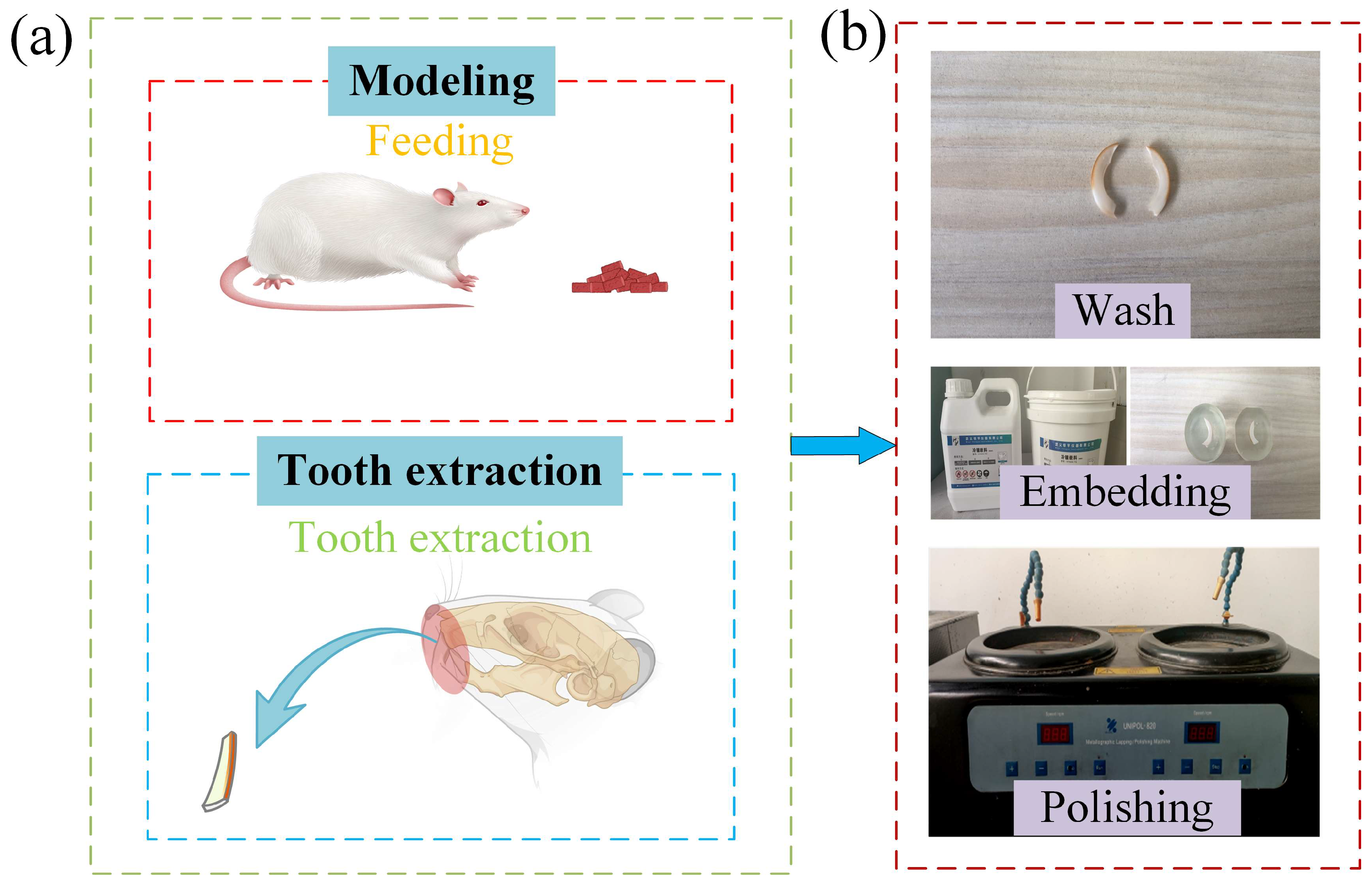
Figure 1. Rat modeling and sample preparation. (a) Rat modeling method; (b) Tooth sample preparation procedure. (Source: Authors own work).
Coatings 15 01255 g001
Figure 2. SEM microstructure of rat tooth enamel. (ac) Microscopic morphology of rat tooth enamel; (df) Morphological comparisons of the outer, middle and inner layers of rat tooth enamel after magnification of 5000× and 50,000×. (Source: Authors own work).
Coatings 15 01255 g002
Figure 3. Three-dimensional model structure of rat tooth enamel. (a) Crystal bundle; (be) Represent the I-type module, II-type module, III-type module, and IV-type module respectively; (f) Represent the crystal bundle arrangement diagrams for indentation simulation and crack simulation, respectively; (g) Represent the outer and inner layers of tooth enamel in indentation simulation, respectively; (h) Represent the outer and inner layers of tooth enamel in crack simulation, respectively. (Source: Authors own work).
Coatings 15 01255 g003
Figure 4. Three-dimensional structures under various boundary conditions. (a) Indentation model; (b) Boundary conditions for indentation simulation; (c) Crack model; (d) Boundary conditions for crack simulation. (Source: Authors own work).
Coatings 15 01255 g004
Figure 5. Comparison of the mechanical properties of enamel from the outer to the inner layer. (a) Indentation points at different levels on the distal surface of the incisors, arranged from the outer to the inner side; (b) A magnified image showing the surface scratches on the outer layer of tooth enamel; (c) A magnified image depicting the depressions in the inner layer of tooth enamel; (d) The differences in Vickers hardness among various layers; (e) The average length of the diagonal of the indentation and average length of crack propagation; (f) Fracture toughness of different layers. (Source: Authors own work).
Coatings 15 01255 g005
Figure 6. Stress distribution maps and data comparison of equivalent stress for the outer and inner layers of enamel with indentation depths of 0.15 μm, 0.25 μm, and 0.35 μm. (a,b) The equivalent stress distribution maps of the outer and inner layers of enamel on the XZ plane under different indentation depths; (c,d) The equivalent stress distribution maps of the outer and inner layers of enamel on the XY plane under different indentation depths. (e) Load-indentation depth response curves of the outer and inner layers of enamel under different indentation depths. (Source: Authors own work).
Coatings 15 01255 g006
Figure 7. Equivalent plastic strain contour plots and data comparisons for the outer and inner layers of enamel with indentation depths of 0.15 μm, 0.25 μm, and 0.35 μm. (a,b)The equivalent strain contour plots of the outer and inner layers of enamel on the XZ plane, respectively; (c) The stress–strain curve of the outer and inner layers of enamel; (d) The plastic energy dissipation curve of the outer and inner layers of enamel. (Source: Authors own work).
Coatings 15 01255 g007
Figure 8. Comparison of crack paths and numerical simulation date for the outer and inner layers of enamel. (a) Outer layer enamel crack path; (b) Inner layer enamel crack path; (c) Energy dissipation curves for outer and inner layer enamel cracks; (d) Time-stress curves for outer and inner layer enamel. (Source: Authors own work).
Coatings 15 01255 g008
Disclaimer/Publisher’s Note: The statements, opinions and data contained in all publications are solely those of the individual author(s) and contributor(s) and not of MDPI and/or the editor(s). MDPI and/or the editor(s) disclaim responsibility for any injury to people or property resulting from any ideas, methods, instructions or products referred to in the content.